JP4555604B2 - Capsule endoscope and capsule endoscope system - Google Patents
Capsule endoscope and capsule endoscope system Download PDFInfo
- Publication number
- JP4555604B2 JP4555604B2 JP2004139890A JP2004139890A JP4555604B2 JP 4555604 B2 JP4555604 B2 JP 4555604B2 JP 2004139890 A JP2004139890 A JP 2004139890A JP 2004139890 A JP2004139890 A JP 2004139890A JP 4555604 B2 JP4555604 B2 JP 4555604B2
- Authority
- JP
- Japan
- Prior art keywords
- illumination
- capsule endoscope
- unit
- timing
- image
- Prior art date
- Legal status (The legal status is an assumption and is not a legal conclusion. Google has not performed a legal analysis and makes no representation as to the accuracy of the status listed.)
- Expired - Fee Related
Links
Images


Classifications
-
- A—HUMAN NECESSITIES
- A61—MEDICAL OR VETERINARY SCIENCE; HYGIENE
- A61B—DIAGNOSIS; SURGERY; IDENTIFICATION
- A61B1/00—Instruments for performing medical examinations of the interior of cavities or tubes of the body by visual or photographical inspection, e.g. endoscopes; Illuminating arrangements therefor
- A61B1/04—Instruments for performing medical examinations of the interior of cavities or tubes of the body by visual or photographical inspection, e.g. endoscopes; Illuminating arrangements therefor combined with photographic or television appliances
- A61B1/041—Capsule endoscopes for imaging
-
- A—HUMAN NECESSITIES
- A61—MEDICAL OR VETERINARY SCIENCE; HYGIENE
- A61B—DIAGNOSIS; SURGERY; IDENTIFICATION
- A61B1/00—Instruments for performing medical examinations of the interior of cavities or tubes of the body by visual or photographical inspection, e.g. endoscopes; Illuminating arrangements therefor
- A61B1/04—Instruments for performing medical examinations of the interior of cavities or tubes of the body by visual or photographical inspection, e.g. endoscopes; Illuminating arrangements therefor combined with photographic or television appliances
-
- A—HUMAN NECESSITIES
- A61—MEDICAL OR VETERINARY SCIENCE; HYGIENE
- A61B—DIAGNOSIS; SURGERY; IDENTIFICATION
- A61B5/00—Measuring for diagnostic purposes; Identification of persons
- A61B5/0002—Remote monitoring of patients using telemetry, e.g. transmission of vital signals via a communication network
- A61B5/0031—Implanted circuitry
Landscapes
- Health & Medical Sciences (AREA)
- Life Sciences & Earth Sciences (AREA)
- Surgery (AREA)
- Engineering & Computer Science (AREA)
- General Health & Medical Sciences (AREA)
- Animal Behavior & Ethology (AREA)
- Pathology (AREA)
- Veterinary Medicine (AREA)
- Public Health (AREA)
- Biophysics (AREA)
- Biomedical Technology (AREA)
- Heart & Thoracic Surgery (AREA)
- Medical Informatics (AREA)
- Molecular Biology (AREA)
- Physics & Mathematics (AREA)
- Optics & Photonics (AREA)
- Nuclear Medicine, Radiotherapy & Molecular Imaging (AREA)
- Radiology & Medical Imaging (AREA)
- Computer Networks & Wireless Communication (AREA)
- Endoscopes (AREA)
Description
本発明は、被検体の内部に導入され、前記被検体の内部の画像を撮像するカプセル型内視鏡およびカプセル型内視鏡システムに関するものである。 The present invention relates to a capsule endoscope and a capsule endoscope system that are introduced into a subject and capture an image inside the subject.
近年、内視鏡の分野においては、飲込み型のカプセル型内視鏡が提案されている。このカプセル型内視鏡には、撮像機能と無線通信機能とが設けられている。カプセル型内視鏡は、観察(検査)のために被検体の口から飲込まれた後、自然排出されるまでの間、体腔内、例えば胃、小腸などの臓器の内部をその蠕動運動に従って移動し、順次撮像する機能を有する。 In recent years, in the field of endoscopes, swallowable capsule endoscopes have been proposed. This capsule endoscope is provided with an imaging function and a wireless communication function. The capsule endoscope is swallowed from the mouth of the subject for observation (examination) until it is spontaneously discharged until it is spontaneously discharged. It has the function of moving and capturing images sequentially.
体腔内を移動する間、カプセル型内視鏡によって体内で撮像された画像データは、順次無線通信により外部に送信され、外部に設けられたメモリに蓄積される。無線通信機能とメモリ機能とを備えた受信機を携帯することにより、被検体は、カプセル型内視鏡を飲み込んだ後、排出されるまでの間に渡って、自由に行動できる。カプセル型内視鏡が排出された後、医者もしくは看護士においては、メモリに蓄積された画像データに基づく臓器の画像をディスプレイに表示させることによって診断を行うことができる。 While moving inside the body cavity, image data captured inside the body by the capsule endoscope is sequentially transmitted to the outside by wireless communication and stored in a memory provided outside. By carrying a receiver having a wireless communication function and a memory function, the subject can freely act after swallowing the capsule endoscope and before being discharged. After the capsule endoscope is ejected, the doctor or nurse can make a diagnosis by displaying an image of the organ based on the image data stored in the memory on the display.
カプセル型内視鏡に備わる撮像機能は、例えば、所定の光学系と、CCD等の撮像素子とによって形成されている。具体的には、カプセル型内視鏡は、光学系によって結像された入射光を電気信号に変換することにより、被検体内部の画像を取得している。 The imaging function provided in the capsule endoscope is formed by, for example, a predetermined optical system and an imaging element such as a CCD. Specifically, the capsule endoscope acquires an image inside the subject by converting incident light imaged by the optical system into an electric signal.
しかしながら、従来のカプセル型内視鏡システムでは、高品位の被検体内画像の取得が容易ではないという課題を有する。具体的には、従来のカプセル型内視鏡システムでは、カプセル型内視鏡の照明輝度の調整および取得される画像データ中の雑音成分の存在により、高品位の被検体内画像を取得することが困難である。以下、かかる課題について詳細に説明する。 However, the conventional capsule endoscope system has a problem that it is not easy to acquire a high-quality in-vivo image. Specifically, in a conventional capsule endoscope system, a high-quality in-subject image is acquired by adjusting the illumination brightness of the capsule endoscope and the presence of noise components in the acquired image data. Is difficult. Hereinafter, this problem will be described in detail.
まず、従来のカプセル型内視鏡では、LEDの照射光量の調整が容易でないという問題がある。すなわち、カプセル型内視鏡は、被検体内に導入可能な程度に小型化する必要があることからカプセルに内蔵される回路も単純な構成であることが好ましく、また、被検体内に導入されてから排出されるまで、例えば8時間程度に渡って駆動する必要があることから、カプセル型内視鏡にそなわる制御回路等は、低消費電力のものを使用する必要がある。 First, the conventional capsule endoscope has a problem that it is not easy to adjust the amount of light emitted from the LED. That is, since the capsule endoscope needs to be miniaturized to such an extent that it can be introduced into the subject, the circuit incorporated in the capsule preferably has a simple configuration, and is also introduced into the subject. For example, it is necessary to drive the capsule endoscope for about 8 hours until it is discharged. Therefore, it is necessary to use a low power consumption control circuit or the like for the capsule endoscope.
このため、カプセル型内視鏡は、例えばディジタルカメラに具備されるような調光機構を搭載することは少なくとも現時点では現実的ではなく、カプセル型内視鏡に特化した調光機構を備える必要がある。しかしながら、現時点で提案されている調光機構の中で、カプセル型内視鏡の使用条件に適合するようなものは必ずしも存在しないのが現状である。 For this reason, it is not realistic at least at present to mount a light control mechanism such as that provided in a digital camera, for example, and it is necessary to provide a light control mechanism specialized for the capsule endoscope. There is. However, at present, there is not necessarily a dimming mechanism proposed at the present time that is suitable for the use conditions of the capsule endoscope.
次に、暗電流に起因した雑音成分が画像データに包含されるという問題について説明する。暗電流とは、CCD等の撮像素子の機構上、入射光と無関係に発生する電流成分をいい、かかる暗電流の量に応じて取得画像データに雑音成分が混入することとなる。 Next, a problem that a noise component due to dark current is included in image data will be described. The dark current refers to a current component that is generated regardless of incident light due to the mechanism of an image sensor such as a CCD, and a noise component is mixed in acquired image data according to the amount of the dark current.
図7は、暗電流の温度依存性の一例について示す模式的なグラフである。図7に示すように、暗電流の強度は温度の上昇につれて単調に増加する傾向を示しており、環境温度が高ければ高いほど、暗電流に起因した雑音成分が増大することとなる。 FIG. 7 is a schematic graph showing an example of temperature dependence of dark current. As shown in FIG. 7, the intensity of the dark current tends to monotonously increase as the temperature rises, and the higher the environmental temperature, the greater the noise component due to the dark current.
ここで、カプセル型内視鏡は、被検体内に導入された状態で撮像動作を行うことから、環境温度としては38℃程度となる。かかる温度条件下でCCD等の撮像素子を使用した場合の暗電流の値は、室温(例えば、20℃)と比較して3〜4倍程度に増加することとなる。従って、カプセル型内視鏡に備わる撮像素子を用いて撮像動作を行った場合には、通常の撮像装置を用いた場合と比較して暗電流の量が増大し、画像の品位に与える影響も大きなものとなる。 Here, since the capsule endoscope performs an imaging operation while being introduced into the subject, the environmental temperature is about 38 ° C. When using an image sensor such as a CCD under such temperature conditions, the value of the dark current increases about 3 to 4 times compared to room temperature (for example, 20 ° C.). Therefore, when an imaging operation is performed using an imaging element provided in a capsule endoscope, the amount of dark current increases as compared with the case of using a normal imaging device, and the image quality is also affected. It will be big.
なお、暗電流の影響を排除するために、CCDを冷却しつつ撮像を行う構成が既に提案され、一部で実用化されている。しかしながら、かかる冷却機構は高い電力を消費することから、カプセル型内視鏡に搭載することは妥当ではなく、他に代替手段も存在しないのが現状である。 In order to eliminate the influence of dark current, a configuration in which imaging is performed while the CCD is cooled has already been proposed, and some have been put into practical use. However, since such a cooling mechanism consumes high power, it is not appropriate to mount it on a capsule endoscope, and there is no alternative means at present.
本発明は、上記に鑑みてなされたものであって、高品位の画像を取得することを可能としたカプセル型内視鏡およびカプセル型内視鏡システムを実現することを目的とする。 The present invention has been made in view of the above, and an object of the present invention is to realize a capsule endoscope and a capsule endoscope system that can acquire a high-quality image.
上述した課題を解決し、目的を達成するために、請求項1にかかるカプセル型内視鏡は、検体の内部に導入され、前記被検体の内部の画像を撮像するカプセル型内視鏡であって、前記被検体の内部表面に対して照明光を照射する照明手段と、入射光に応じた電気信号を生成し、生成した電気信号を出力する撮像手段と、暗電流に起因して前記撮像手段に蓄積された雑音電荷を除去する雑音除去手段と、前記雑音除去手段の駆動タイミングを、前記撮像手段による電気信号の出力動作の完了後であって、前記照明手段による照明光の照射開始前の期間となるよう制御するタイミング制御手段と、前記撮像手段によって撮像された画像の輝度と、所定の基準輝度とを比較する比較手段と、前記比較手段による比較結果に基づいて前記照明手段から出力される照明光の発光量を調整する発光量調整手段と、を備え、前記タイミング制御手段は、前記発光量調整手段によって前記照明手段の駆動期間が調整された際に、前記照明手段の駆動停止タイミングを一定に維持しつつ前記照明手段の駆動開始タイミングを前記照明手段の駆動期間に応じて変化させることを特徴とする。 In order to solve the above-described problems and achieve the object, a capsule endoscope according to claim 1 is a capsule endoscope that is introduced into a specimen and captures an image inside the specimen. The illumination means for irradiating the inner surface of the subject with illumination light, the imaging means for generating an electrical signal corresponding to the incident light, and outputting the generated electrical signal, and the imaging due to dark current The noise removal means for removing the noise charge accumulated in the means, and the drive timing of the noise removal means after the completion of the output operation of the electrical signal by the imaging means and before the start of illumination light irradiation by the illumination means and timing control means for controlling so as to be a period of the luminance of the image captured by the imaging means, and comparing means for comparing the predetermined reference luminance, from said illuminating means based on a comparison result by the comparing means A light emission amount adjusting means for adjusting a light emission amount of the illumination light to be applied, and the timing control means drives the illumination means when the drive period of the illumination means is adjusted by the light emission amount adjustment means. The drive start timing of the illumination unit is changed according to the drive period of the illumination unit while maintaining a stop timing constant.
この請求項1の発明によれば、雑音除去手段の駆動タイミングを撮像手段の出力動作の完了後であって、照明光の照射開始前の期間に駆動させるタイミング制御手段を備えることとしたため、電気信号の出力動作および入射光に起因した電気信号の生成に悪影響を及ぼすことなく、暗電流に起因した雑音成分の除去を行うことができる。 According to the first aspect of the invention, since the drive timing of the noise removing means is provided after the completion of the output operation of the imaging means and before the illumination light irradiation is started, the timing control means is provided. The noise component due to the dark current can be removed without adversely affecting the signal output operation and the generation of the electrical signal due to the incident light.
また、請求項2にかかるカプセル型内視鏡は、上記の発明において、前記タイミング制御手段は、前記照明手段の駆動開始タイミングと、前記雑音除去手段の駆動停止タイミングとが同時となるよう制御動作を行うことを特徴とする。 In the capsule endoscope according to a second aspect of the present invention, in the above invention, the timing control unit performs a control operation so that the drive start timing of the illumination unit and the drive stop timing of the noise removal unit are simultaneous. It is characterized by performing.
また、請求項3にかかるカプセル型内視鏡は、上記の発明において、前記比較手段は、前記画像輝度と前記基準輝度との間の大小関係を導出し、前記発光量調整手段は、前記画像輝度が前記基準輝度を上回る値である場合に前記照明手段の駆動期間を所定量だけ減少させ、前記画像輝度が前記基準輝度を下回る値である場合に前記照明手段の駆動期間を所定量だけ増加させるよう調整を行うことを特徴とする。 The capsule endoscope according to claim 3, in the above invention, the comparison means derives a magnitude relationship between the image luminance and the reference luminance, the light emitting amount adjusting means, the image When the luminance is higher than the reference luminance, the driving period of the illumination unit is decreased by a predetermined amount, and when the image luminance is lower than the reference luminance, the driving period of the lighting unit is increased by a predetermined amount. It is characterized in that adjustment is performed.
また、請求項4にかかるカプセル型内視鏡システムは、被検体内に導入され、該被検体内の画像を撮像すると共に画像データを含む無線信号を外部に無線送信するカプセル型内視鏡と、該カプセル型内視鏡から送信された無線信号を受信する受信装置とを備えたカプセル型内視鏡システムであって、前記受信装置は、前記カプセル型内視鏡から送信された無線信号を受信する受信用アンテナ手段と、前記受信用アンテナ手段によって受信された無線信号に対して所定の処理を行う外部装置とを備え、前記カプセル型内視鏡は、前記被検体の内部表面に対して照明光を照射する照明手段と、入射光に応じた電気信号を出力する光電変換素子を搭載した撮像手段と、暗電流に起因して前記撮像手段に蓄積された雑音電荷を除去する雑音除去手段と、前記雑音除去手段の駆動タイミングを、前記撮像手段による電気信号の出力動作の完了後であって、前記照明手段による照明光の照射開始前の期間となるよう制御するタイミング制御手段と、前記撮像手段によって撮像された画像データを含む無線信号を外部に送信する無線手段と、前記撮像手段によって撮像された画像の輝度と、所定の基準輝度とを比較する比較手段と、前記比較手段による比較結果に基づいて前記照明手段から出力される照明光の発光量を調整する発光量調整手段と、を備え、前記タイミング制御手段は、前記発光量調整手段によって前記照明手段の駆動期間が調整された際に、前記照明手段の駆動停止タイミングを一定に維持しつつ前記照明手段の駆動開始タイミングを前記照明手段の駆動期間に応じて変化させることを特徴とする。 A capsule endoscope system according to claim 4 is introduced into a subject, captures an image in the subject, and wirelessly transmits a wireless signal including image data to the outside. A capsule endoscope system including a receiving device that receives a radio signal transmitted from the capsule endoscope, wherein the receiving device receives a radio signal transmitted from the capsule endoscope. A receiving antenna means for receiving, and an external device for performing a predetermined process on a radio signal received by the receiving antenna means, wherein the capsule endoscope is disposed on the inner surface of the subject. Illuminating means for irradiating illumination light, imaging means equipped with a photoelectric conversion element that outputs an electrical signal corresponding to incident light, and noise removing means for removing noise charges accumulated in the imaging means due to dark current When Timing control means for controlling the drive timing of the noise removing means to be a period after completion of the output operation of the electrical signal by the imaging means and before the start of irradiation of illumination light by the illumination means; and the imaging means Wireless means for transmitting to the outside a wireless signal including image data captured by the imaging means, comparison means for comparing the brightness of the image captured by the imaging means with a predetermined reference brightness, and a comparison result by the comparison means A light emission amount adjusting means for adjusting the light emission amount of the illumination light output from the illumination means based on the timing control means when the drive period of the illumination means is adjusted by the light emission amount adjusting means. The drive start timing of the illumination means is changed according to the drive period of the illumination means while maintaining the drive stop timing of the illumination means constant. And wherein the door.
また、請求項5にかかるカプセル型内視鏡システムは、上記の発明において、前記タイミング制御手段は、前記照明手段の駆動開始タイミングと、前記雑音除去手段の駆動停止タイミングとが同時となるよう制御することを特徴とする。
In the capsule endoscope system according to
本発明にかかるカプセル型内視鏡およびカプセル型内視鏡システムは、雑音除去手段の駆動タイミングを撮像手段の出力動作の完了後であって、照明光の照射開始前の期間に駆動させるタイミング制御手段を備えることとしたため、電気信号の出力動作および入射光に起因した電気信号の生成に悪影響を及ぼすことなく、暗電流に起因した雑音成分の除去を行うことができるという効果を奏する。 In the capsule endoscope and the capsule endoscope system according to the present invention, the timing control is performed so that the drive timing of the noise removing unit is driven after the output operation of the imaging unit is completed and before the illumination light irradiation is started. By providing the means, the noise component caused by the dark current can be removed without adversely affecting the output operation of the electric signal and the generation of the electric signal caused by the incident light.
以下、この発明を実施するための最良の形態(以下、単に「実施の形態」と称する)であるカプセル型内視鏡システムについて説明する。なお、図面は模式的なものであり、各部分の厚みと幅との関係、それぞれの部分の厚みの比率などは現実のものとは異なることに留意すべきであり、図面の相互間においても互いの寸法の関係や比率が異なる部分が含まれていることはもちろんである。 A capsule endoscope system that is the best mode for carrying out the present invention (hereinafter simply referred to as “embodiment”) will be described below. Note that the drawings are schematic, and it should be noted that the relationship between the thickness and width of each part, the ratio of the thickness of each part, and the like are different from the actual ones. Of course, the part from which the relationship and ratio of a mutual dimension differ is contained.
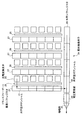
図1は、本実施の形態にかかるカプセル型内視鏡システムの全体構成を示す模式図である。本実施の形態にかかるカプセル型内視鏡システムは、被検体1の内部に導入されて被検体内画像の撮像を行い、撮像したデータを外部に対して無線送信するカプセル型内視鏡2と、カプセル型内視鏡2の被検体1内部における位置の検出を行う受信装置3と、受信装置3によって受信された画像データの内容を表示する表示装置4と、受信装置3と表示装置4との間の情報の受け渡しを行うための携帯型記録媒体5とを備える。
FIG. 1 is a schematic diagram showing an overall configuration of a capsule endoscope system according to the present embodiment. The capsule endoscope system according to the present embodiment includes a
表示装置4は、カプセル型内視鏡2によって撮像された被検体内画像を表示するためのものであり、携帯型記録媒体5を介して得られるデータに基づいて画像表示を行うワークステーション等のような構成を有する。具体的には、表示装置4は、CRTディスプレイ、液晶ディスプレイ等によって直接画像を表示する構成としても良いし、プリンタ等のように、他の媒体に画像を出力する構成としても良い。
The display device 4 is for displaying an in-vivo image picked up by the
携帯型記録媒体5は、後述する外部装置8および表示装置4に対して着脱可能であって、両者に対する装着時に情報の出力および記録が可能な構造を有する。具体的には、携帯型記録媒体5は、カプセル型内視鏡2が被検体1の内部を移動している間は外部装置8に挿着されてカプセル型内視鏡2の位置に関する情報を記録する。そして、カプセル型内視鏡2が被検体1から排出された後に、外部装置8から取り出されて表示装置4に装着され、記録したデータが表示装置4によって読み出される構成を有する。外部装置8と表示装置4との間のデータの受け渡しをコンパクトフラッシュ(登録商標)メモリ等の携帯型記録媒体5によって行うことで、外部装置8と表示装置4との間が有線接続された場合と異なり、カプセル型内視鏡2が被検体1内部を移動中であっても、被検体1が自由に行動することが可能となる。
The
受信装置3は、カプセル型内視鏡2から無線送信された画像データを受信し、必要に応じて所定の処理を施した上で画像データを携帯型記録媒体5に記録するためのものである。具体的には、受信装置3は、受信用アンテナ7a〜7hと外部装置8とによって構成され、受信用アンテナ7a〜7hのいずれかを介してカプセル型内視鏡2から送信された無線信号を受信すると共に、無線信号の中から画像データを抽出する等の処理を行った上で携帯型記録媒体5に対して画像データを出力する機能を有する。
The receiving device 3 is for receiving the image data wirelessly transmitted from the
次に、カプセル型内視鏡2について説明する。カプセル型内視鏡2は、図1に示すカプセル形状の外形を備え、所定の構成要素をかかる外形のカプセル内に備えることによって形成されている。なお、カプセル型内視鏡2を構成するカプセルの形状としては、例えば回転楕円体状のものが考えられるが、本実施の形態においては、カプセルの形状を特に限定して考える必要はなく、被検体1にとって飲み込みやすい形状であれば任意の形状を用いることとして良い。
Next, the
図2は、カプセル型内視鏡2の内部構成を示すブロック図である。カプセル型内視鏡2は、被検体内画像の撮像等を行うための第1の機構と、撮像時における照明光の強度を調整するための第2の機構と、カプセル型内視鏡2に備わる各構成要素の駆動タイミングを規定するための第3の機構とを備える。以下、各機構の構成等についてそれぞれ説明する。
FIG. 2 is a block diagram showing an internal configuration of the
図2に示すように、本実施の形態におけるカプセル型内視鏡2は、第1の機構として、被検体内画像を撮像し、外部に送信するための機構を有する。すなわち、カプセル型内視鏡2は、被検体1の内部に所定の照明光を照射するための照明部11と、照明部11から出力された照明光の反射光を入射し、入射光の強度に対応したアナログ電気信号を出力する撮像部12と、撮像部12から出力されたアナログ電気信号をディジタル電気信号に変換するA/D変換部13と、A/D変換部13から出力されるディジタル電気信号に対して必要な処理を施し、外部に無線送信するための無線送信部15とを備える。
As shown in FIG. 2, the
照明部11は、被検体1内部を照射する照明光を出力するためのものであり、かかる照明光を出力することにより、撮像部12による被検体内画像の撮像を可能にしている。照明部11は、具体的には、例えばLED等の発光機構および発光機構の駆動制御回路によって形成され、後述するタイミング制御部20によって与えられるタイミングで発光動作を行う機能を有する。
The
撮像部12は、被検体1内部の画像を撮像するためのものである。具体的には、撮像部12は、入射光を結像するための光学系と、光学系によって結像された入射光の強度に応じた電気信号を出力することによって、被検体1内部の画像を撮像する機能を有する。
The
図3は、撮像部12を構成する撮像素子の一例として、いわゆるインターライン方式のCCD素子によって構成される固体撮像素子24の構造を示す模式図である。図3に示す固体撮像素子24は、行列状に配置された複数の光電変換素子25と、光電変換素子25によって形成される行列の列方向に延伸し、行数に対応して複数配置されたトランスファーゲート26および垂直シフトレジスタ27と、垂直シフトレジスタ27の電荷出力方向下流に配置され、行方向に延伸した構成を有する水平シフトレジスタ28と、水平シフトレジスタ28から出力された電荷を電圧信号に変換する電圧変換部29と、電圧変換部29から出力された電圧信号を増幅する増幅部30とを備える。なお、固体撮像素子24において、光電変換素子25によって構成される行列の行数および列数は、図3に示したものに限定して解釈する必要はなく、実際には撮像画像の画素数に応じて定められるものである。
FIG. 3 is a schematic diagram showing a structure of a solid-state imaging device 24 constituted by a so-called interline type CCD device as an example of the imaging device constituting the
光電変換素子25は、入射光の強度に応じた電気信号を生成するためのものである。光電変換素子25は、例えばフォトダイオードによって構成されており、入射光に応じた電荷を蓄積する機能を有する。
The
トランスファーゲート26は、光電変換素子25から垂直シフトレジスタ27に対する電荷の移動を制御するためのものである。具体的には、トランスファーゲート26は、電極(図示省略)によって印加される電位に応じたポテンシャルを有するよう構成されており、かかるポテンシャルの値を変化することによって、光電変換素子25によって得られた電荷が垂直シフトレジスタ27側に移動する。
The
垂直シフトレジスタ27は、光電変換素子25から出力された電荷を列方向に移動させるためのものである。具体的には、垂直シフトレジスタ27は、行数に応じて配置された井戸型ポテンシャル31および井戸型ポテンシャル31のポテンシャルを制御するための電極(図示省略)によって構成され、井戸型ポテンシャル31のポテンシャルを順次変化させることによって、光電変換素子25から移動された電荷を列方向に移動させて水平シフトレジスタ28に出力する機能を有する。
The
水平シフトレジスタ28は、電荷を行方向に移動させるためのものである。具体的には、水平シフトレジスタ28は、光電変換素子25によって形成される行列の列数に対応した井戸型ポテンシャル32を備えた構成を有し、かかる井戸型ポテンシャル32のポテンシャルを順次制御することによって、電荷を電圧変換部29に対して順次出力する機能を有する。
The horizontal shift register 28 is for moving charges in the row direction. Specifically, the horizontal shift register 28 has a configuration including a well-
無線送信部15は、撮像部12によって撮像され、A/D変換部13によってディジタル信号に変換された画像データを無線送信するためのものである。無線送信部15は、具体的には、例えば画像データに対して必要に応じて変調処理等を施すことによって無線信号を生成する送信回路と、生成された無線信号を外部に送信するための送信用アンテナとによって構成される。
The
また、カプセル型内視鏡2は、第2の機構として、照明部11による発光量を調整する機構を有する。具体的には、カプセル型内視鏡2は、A/D変換部13から出力されたディジタル信号に基づいて、撮像部12によって撮像された画像の画像輝度を導出する画像輝度導出部16と、所定の基準輝度に関する情報を取得する基準輝度情報保持部17と、画像輝度と基準輝度とを比較する比較部18と、比較部18による比較結果に基づいて、照明部11における発光量を調整する発光量調整部19とを備える。
In addition, the
画像輝度導出部16は、撮像部12によって撮像された画像の画像輝度を導出するためのものである。すなわち、画像輝度導出部16は、撮像された画像データを構成する各画素の輝度値を積算すると共に、積算結果を画素数で除算することによって、単一画素の平均的な輝度を導出する機能を有する。かかる機能を実現するため、画像輝度導出部16は、例えば検波回路を備えた構成を有する。
The image
基準輝度情報保持部17は、あらかじめ定めた基準輝度に関する情報を保持するためのものである。具体的には、基準輝度情報保持部17は、例えば表示装置4における表示能力に対応すると共に使用者にとって画像内容が容易に視認可能な輝度を基準輝度として定めると共に、かかる基準輝度に対応した情報を保持する機能を有する。本実施の形態では、基準輝度情報保持部17は、基準輝度情報として基準輝度に対応した電圧値を保持することとし、具体的には、基準輝度に対応した電圧値を出力する定電圧源を備えて構成されることとする。
The reference luminance
比較部18は、画像輝度導出部16によって導出される画像輝度と、基準輝度情報保持部17によって保持された基準輝度とを比較し、比較結果を発光量調整部19に対して出力するためのものである。なお、比較部18によって出力される比較結果としては、画像輝度と基準輝度との間の相関関係に応じたものであれば任意のものとして良いが、本実施の形態においては、比較部18によって導出される比較結果として、単純に画像輝度と基準輝度との間の大小関係を出力することとする。
The
発光量調整部19は、比較部18によって得られた比較結果に基づいて、照明部11から出力される照明光の光量を調整するためのものである。具体的には、発光量調整部19は、比較部18によって導出された比較結果に基づき照明部11から出力される照明光の出力時間を変化させ、変化した出力時間に関する情報をタイミング制御部20に対して出力する機能を有する。
The light emission
なお、発光量の調整態様としては、照明光の出力時間のみならず、例えば照明部11を構成するLEDに対する注入電流値の調整等も挙げられ、これらの手法によって発光量を調整することとしても良い。しかしながら、本実施の形態においては、消費電力増加の抑制および制御アルゴリズムの簡易化の観点より、照明部11に備わるLED等の発光素子の発光輝度については変化させず、発光時間を変化させることによって発光量を調整することとしている。また、発光量調整部19による照明光の出力時間の導出は、基準輝度と画像輝度との間の差が減少するよう出力時間を調整するものであれば任意のアルゴリズムを用いることが可能である。しかしながら、本実施の形態では、簡易な構成を実現する等の理由により、比較部18が単に大小関係を出力する構成に対応して、画像輝度が基準輝度を上回る場合には一律に所定時間量だけ照明光の出力時間を減少させ、画像輝度が基準輝度を下回る場合には一律に所定時間量だけ照明光の出力時間を増加させることとする。
In addition, as an adjustment mode of the light emission amount, not only the output time of the illumination light but also adjustment of the injection current value for the LED constituting the
さらに、カプセル型内視鏡2は、第3の機構として、各構成要素の駆動タイミングを規定する機構を有する。具体的には、カプセル型内視鏡2は、各構成要素の動作タイミングを制御するタイミング制御部20と、タイミング制御部20の制御に基づいて、撮像部12およびA/D変換部13に対して駆動タイミング等を供給するタイミングジェネレータ21とを備える。また、カプセル型内視鏡2は、上記した各構成要素に対して駆動電力を供給するための蓄電池22を備える。
Furthermore, the
タイミングジェネレータ21は、撮像部12およびA/D変換部13に対して駆動タイミングを供給すると共に、撮像部12に蓄積された、暗電流に起因する雑音成分を除去するためのシャッターパルス(リセットパルス)を出力するためのものである。具体的には、タイミングジェネレータ21は、タイミング制御部20からの指示に基づいて、撮像部12およびA/D変換部13の駆動タイミングを供給すると共に、撮像部12に対してシャッターパルスを供給する機能を有する。
The
雑音成分の除去について簡単に説明する。従来技術においても述べたように、光電変換素子25を用いて撮像部12を備えた構成の場合には、照明部11から照明光が照射されていない、すなわち、固体撮像素子24に対して光が入射しない期間においても、暗電流に起因した電荷が蓄積されることとなる。かかる電荷が残存することによって、撮像動作を経て行列状に配置された光電変換素子25から外部に出力される電荷には入射光と無関係な暗電流に起因した成分が含まれることとなり、画像品位の低下の原因となる。
The removal of noise components will be briefly described. As described in the prior art, in the case of the configuration including the
このため、本実施の形態では、後に詳細に説明するように照明部11による照明光の出力動作を行う前に、暗電流に起因し、雑音成分として機能する電荷を除去することとしている。具体的には、タイミングジェネレータ21によって、撮像部12に対してシャッターパルス(リセットパルス)が供給される。かかるシャッターパルスが供給されることによって、例えば光電変換素子25全体に対して所定の電位が供給され、暗電流に起因して蓄積されていた電荷が放出されることとなる。この意味で、本実施の形態においてタイミングジェネレータ21は、雑音除去手段として機能することとなり、タイミングジェネレータ21は、タイミング制御部20からの指示によって所定のタイミングでシャッターパルスを撮像部12に対して供給し、雑音成分を除去することとしている。
For this reason, in the present embodiment, as will be described in detail later, before the
次に、タイミング制御部20について説明する。タイミング制御部20は、発光量調整部19からの出力に基づいて、照明部11、撮像部12、A/D変換部13および画像輝度導出部16等の動作タイミングを規定するためのものである。具体的には、これらの構成要素はタイミング制御部20から出力されるパルスまたはタイミング制御部20の制御に基づいてタイミングジェネレータ21から出力されるパルスに従って駆動する構成を有することとしている。本実施の形態においては、タイミング制御部20は、かかるパルスの立ち上がり時および立ち下がり時を制御することによって、上記構成要素の動作タイミングを制御している。
Next, the
図4は、タイミング制御部20によって制御されるパルスの供給タイミングを示すタイミングチャートである。まず、タイミング制御部20の制御に基づいて、撮像動作の開始、具体的には光電変換素子25に蓄積された電荷を垂直シフトレジスタ27および水平シフトレジスタ28によって出力する動作の開始タイミングを規定する開始パルスが生成される。かかる開始パルスの供給間隔によって、図4にも示すように、1画像の取得に要する撮像期間Tが規定されている。開始パルスが供給されることによって、固体撮像素子24は、光電変換素子25に蓄積された電荷を垂直シフトレジスタ27に移動させると共に、垂直シフトレジスタ27および水平シフトレジスタ28等の作用により撮像画像に対応したアナログ電気信号が出力され、かかる出力タイミングと同期してA/D変換部13の処理が行われ、ディジタル電気信号によって構成された画像データが生成されることとなる。
FIG. 4 is a timing chart showing the pulse supply timing controlled by the
また、撮像期間の後半において、例えば次の撮像期間の開始を規定する開始パルスが供給される直前において、照明部11の駆動タイミングを規定する照明部駆動パルスが供給される。ここで、本実施の形態における照明部駆動パルスは、立ち上がり時に照明部11の駆動開始タイミングを規定し、立ち下がり時に照明部11の駆動停止タイミングを規定する。照明部11はかかる照明部駆動パルスに従って動作し、図4に示す例では、開始パルスが供給される直前、すなわち固体撮像素子24における電荷の移送が開始される直前に、照明部11は照明光を出力する。
Further, in the second half of the imaging period, for example, immediately before the start pulse that defines the start of the next imaging period is supplied, the illumination unit drive pulse that defines the drive timing of the
さらに、撮像期間の後半において、シャッターパルスが供給される。シャッターパルスは、少なくとも同一の撮像期間における撮像部のデータ出力動作完了後であって、照明部11の駆動が開始される前に供給されており、図4に示す例では、照明部駆動パルスの立ち上がりと同時に立ち下がるようにシャッターパルスの供給タイミングは制御されている。
Furthermore, a shutter pulse is supplied in the second half of the imaging period. The shutter pulse is supplied after completion of the data output operation of the imaging unit in at least the same imaging period and before the driving of the
次に、発光量調整部19による発光量調整動作と、発光量調整部19からの出力に基づいて、タイミング制御部20によって行われるパルス供給タイミングの変動制御について説明する。タイミング制御部20は、基本的には図4に示す態様のパルスを供給するための制御を行う一方で、発光量調整部19からの出力値に応じて各パルスの供給タイミングを変動させる機能をも有する。すなわち、発光量調整部19は、既に説明したように、照明部11から出力される照明光の出力時間を変化させることによって発光量を調整する機構を有する。このため、発光量調整部19によって調整された発光量の照明光を出力するためには、照明部駆動パルスの時間幅を増加させる必要があると共に、図4に示す他のパルスの供給タイミングについても変化させる必要がある。従って、タイミング制御部20は、発光量調整部19からの出力に基づいて、これらのパルスの供給タイミング変動についても制御している。
Next, fluctuation control of the pulse supply timing performed by the
図5は、発光量調整部19によって行われる発光量調整動作と、発光量調整動作に引き続いてタイミング制御部20によって行われるパルス供給タイミングの変動制御について示すフローチャートである。図5に示すように、まず、発光量調整部19は、比較部18によって導出された比較結果を入力し(ステップS101)、比較結果に基づき画像輝度と基準輝度との大小関係を判定する(ステップS102)。画像輝度が基準輝度を上回る場合には(ステップS102,Ir>Is)、表示部駆動パルスの時間幅tをt−Δtに変化させる(ステップS103)。また、画像輝度が基準輝度を下回る場合には(ステップS102,Ir<Is)、表示部駆動パルスの時間幅tをt+Δtに変化させる(ステップS104)。さらに、画像輝度と基準輝度とが等しい場合には(ステップS102,Ir=Is)、表示部駆動パルスの時間幅tの値を維持する(ステップS105)。そして、ステップS103、S104、S105のそれぞれのステップにおいて定められた表示駆動パルスの時間幅の値をタイミング制御部20に対して出力する(ステップS106)。
FIG. 5 is a flowchart illustrating the light emission amount adjustment operation performed by the light emission
次に、タイミング制御部20の動作について説明する。まず、タイミング制御部20は、発光量調整部19から出力された表示駆動パルスの時間幅の具体的な値を入力する(ステップS107)。そして、把握した時間幅となるよう、表示駆動パルスの立ち下げ時を固定しつつ、立ち上げ時を変化させる(ステップS108)。その後、表示駆動パルスの立ち上げ時の変化にあわせて、表示駆動パルスの立ち上がり時と立ち下がり時とが一致するように、シャッターパルスの立ち上がりタイミングおよび立ち下がり時を変化させる(ステップS109)。以上の動作によって、照明部11の照明光出力期間の変動に伴う各動作パルスのタイミングが調整され、各構成要素に対して伝達され、タイミング制御部20の動作が完了する。
Next, the operation of the
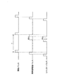
ステップS108、S109における動作について簡単に説明する。図6は、ステップS108、S109において行われるタイミング変動の内容を示す模式図である。既に述べたように、本実施の形態では、照明部11の駆動時間を調整することによって、照明部11によって出力される照明光の光量を変化させることとしている。このため、照明部駆動パルスの時間幅を変化させることとしているのであるが、具体的な変化の態様としては、パルスの立ち上がり時のみを変更する、パルスの立ち下がり時のみを変更する、立ち上がり時および立ち下がり時の双方を変更する3通りの変化態様が考えられる。
The operation in steps S108 and S109 will be briefly described. FIG. 6 is a schematic diagram showing the contents of the timing variation performed in steps S108 and S109. As already described, in the present embodiment, the amount of illumination light output by the
かかる複数の態様の中で、本実施の形態ではステップS108において、図6に示すように、照明部駆動パルスの立ち下がり時を変化すること無く、立ち上がり時のみを変更することによってパルスの時間幅を調整することとしている。タイミング制御部20がかかる制御動作を行うことによって、開始パルス、撮像部出力タイミングが供給されるタイミングは、照明部駆動パルスの時間幅の変化にかかわらず、一定のタイミングに維持されることとなる。
Among the plurality of aspects, in this embodiment, in step S108, as shown in FIG. 6, the time width of the pulse is changed by changing only the rising time without changing the falling time of the illumination unit driving pulse. Is going to be adjusted. When the
また、ステップS109における制御動作によって、シャッターパルスの立ち上がり時および立ち下がり時は、図6に示すように変化する。すなわち、ステップS108において変化した照明部駆動パルスの立ち上がり時にあわせてシャッターパルスの立ち下がり時が変化して照明部駆動パルスの立ち上がり時とシャッターパルスの立ち下がり時とが一致した状態を維持すると共に、立ち下がり時の変化に対応して立ち上がり時も変化している。なお、本実施の形態では、シャッターパルスの時間幅は、照明部駆動パルスの時間幅の変化にかかわらず一定値に維持されることとし、このため、シャッターパルスの立ち下がり時および立ち上がり時は、照明部駆動パルスの立ち上がり時の変化量と等しい量だけ時間変化することとなる。 Also, the control operation in step S109 changes as shown in FIG. 6 when the shutter pulse rises and falls. That is, the falling time of the shutter pulse is changed in accordance with the rising edge of the illumination unit driving pulse changed in step S108, and the rising time of the lighting unit driving pulse and the falling time of the shutter pulse are kept in agreement with each other. Corresponding to the change at the fall, it also changes at the rise. In the present embodiment, the time width of the shutter pulse is maintained at a constant value regardless of the change in the time width of the illumination unit driving pulse.For this reason, when the shutter pulse falls and rises, It changes over time by an amount equal to the amount of change at the rise of the illumination unit drive pulse.
次に、本実施の形態にかかるカプセル型内視鏡システムの利点について説明する。まず、本実施の形態にかかるカプセル型内視鏡システムでは、カプセル型内視鏡2において、暗電流に起因して蓄積された電荷を除去する構成を採用している。かかる構成とすることによって、暗電流に起因した雑音成分が撮像画像データ中に混入することを防止することが可能である。
Next, advantages of the capsule endoscope system according to the present embodiment will be described. First, the capsule endoscope system according to the present embodiment employs a configuration in which the
なお、かかる暗電流の除去を行うタイミング(すなわち、シャッターパルスを供給するタイミング)として、本実施の形態では、少なくとも単一の撮像期間内において撮像部の出力が完了した後であって、照明部駆動パルスが供給される前としている。かかるタイミングとした理由は以下の通りである。すなわち、照明部駆動パルスが供給された後にシャッターパルスを供給した場合には、光電変換素子25によって入射光に対応して生成された電荷についてもあわせてキャンセルされることとなり、高品位の画像データの取得の観点からは妥当ではない。このため、本実施の形態においては、照明部駆動パルスが供給される前にシャッターパルスを供給することとし、かかるタイミングでシャッターパルスを供給することによって、入射光に対応した電荷に悪影響を及ぼすことなく雑音成分の除去を可能としている。
Note that in this embodiment, the timing for performing the dark current removal (that is, the timing for supplying the shutter pulse) is after the output of the imaging unit is completed within at least a single imaging period, and the illumination unit This is before the drive pulse is supplied. The reason for this timing is as follows. That is, when the shutter pulse is supplied after the illumination unit driving pulse is supplied, the charge generated in response to the incident light by the
また、シャッターパルスは、高強度のパルス信号によって構成されるのが通常である。このため、固体撮像素子24に備わる垂直シフトレジスタ27および水平シフトレジスタ28によって電荷を移送している、すなわち撮像部12からアナログ電気信号を出力している際にシャッターパルスを供給した場合には、電荷の移送に悪影響を及ぼすおそれがある。従って、本実施の形態においては、撮像部12からのアナログ電気信号の出力が完了した後にシャッターパルスを供給することとし、かかるタイミングでシャッターパルスを供給することによって、電荷の移送に悪影響を及ぼすことなく雑音成分の除去を可能としている。
The shutter pulse is usually composed of a high-intensity pulse signal. Therefore, when charges are transferred by the
また、本実施の形態では、シャッターパルスの供給タイミングを照明部駆動パルスの供給の直前、より好ましくは図4、図6の例に示すように照明部駆動パルスの立ち上がり時にシャッターパルスの立ち下がり時が一致するよう制御している。かかる構成とすることにより、本実施の形態にかかるカプセル型内視鏡システムは、暗電流に起因した雑音成分の除去をより確実に行うことが可能であるという利点を有する。すなわち、暗電流に起因した電荷は、撮像期間全般に渡って徐々に蓄積されるものであることから、一度シャッターパルスを供給して雑音成分を除去しても、その後再び暗電流に起因した雑音成分の蓄積が行われることとなる。従って、本実施の形態では、シャッターパルスの除去を被検体内画像に対応した光が光電変換素子25に入射するタイミング(すなわち、照明部駆動パルスが供給されるタイミング)の直前、より好ましくは照明部駆動パルスが立ち上がる時点に、シャッターパルスが立ち下がる構成とし、かかる構成により、より確実な雑音成分が除去できるという利点を享受している。 In this embodiment, the shutter pulse supply timing is set immediately before the illumination unit drive pulse is supplied, more preferably at the fall of the shutter pulse at the rise of the illumination unit drive pulse as shown in the examples of FIGS. Are controlled to match. With this configuration, the capsule endoscope system according to the present embodiment has an advantage that noise components caused by dark current can be more reliably removed. In other words, since the charge caused by the dark current is gradually accumulated over the entire imaging period, once the noise component is removed by supplying the shutter pulse once, the noise caused by the dark current is then returned again. Accumulation of components will be performed. Therefore, in this embodiment, the removal of the shutter pulse is performed immediately before the timing at which the light corresponding to the in-subject image enters the photoelectric conversion element 25 (that is, the timing at which the illumination unit driving pulse is supplied), and more preferably illumination. The configuration is such that the shutter pulse falls when the part drive pulse rises, and this configuration enjoys the advantage that more reliable noise components can be removed.
さらに、本実施の形態では、実際に撮像された画像の輝度である画像輝度と、表示装置4の表示特性等によって定まる所定の基準輝度との比較結果に基づいて照明部11から出力される照明光の出力時間を変化させる構成を有する。従って、本実施の形態におけるカプセル型内視鏡2は、基準輝度と近似した輝度を有する高品位な画像データを取得することが可能であるという利点を有する。
Furthermore, in the present embodiment, the illumination output from the
特に、本実施の形態では、比較部18は画像輝度と基準輝度との間の大小関係のみを導出することとしている。発光量調整部19が用いる比較結果として、画像輝度と基準輝度との間の大小関係のみを導出することとしたため、比較部18は、いわゆるオペアンプと抵抗素子等を用いた比較器によって構成することが可能である。かかる比較器は構成が簡易であると共に消費電力も低い値に抑制されることから、カプセル型内視鏡2に内蔵する構成としても、カプセル型内視鏡2の大型化および消費電力の増加といった問題を回避することが可能である。
In particular, in the present embodiment, the
また、発光量調整部19は、比較部18で得られた大小関係に基づいて、照明光の出力時間を、あらかじめ定めた時間(図5のフローチャートにおけるΔt)だけ変化させる構成を採用している。すなわち、発光量調整部19は、図5のフローチャートにも示したように、画像輝度が基準輝度を上回る場合には照明光の出力時間をΔtだけ減じ、画像輝度が基準輝度を下回る場合には照明光の出力時間をΔtだけ増やすよう機能している。かかる構成を採用することによって、発光量調整部19における演算量を低減することが可能であると共に、発光量調整部19を実現するための電子回路等の構成を単純化することが可能である。従って、発光量調整部19についても小型かつ低消費電力の構成を採用することが可能である。
In addition, the light emission
なお、被検体1内部に導入されて被検体内画像を撮像するカプセル型内視鏡2の場合には、上記のメカニズムによって発光量の調整を行った場合でも、充分実用に耐えるものとなる。すなわち、被検体1内部における入射光量の変化は、例えば室内から室外に移動した際のようなダイナミックなものではなく、連続的かつ緩やかな変化となるのが通常である。このため、上記したような簡易な構成であっても、入射光量の変化に対応した発光量の導出について、実用上問題ない程度に行うことが可能である。
In the case of the
さらに、本実施の形態では、タイミング制御部20についても簡易な構成とすることが可能である。すなわち、図4および図6に示したように、開始パルスの供給タイミングは一定の周期に維持されると共に、照明部駆動パルスの立ち下がり時は、開始パルスの立ち上がり時と一致するよう規定されている。さらに、タイミング制御部20は、照明部駆動パルスの時間幅が変動した場合であっても、照明部駆動パルスの立ち上がり時とシャッターパルスの立ち下がり時とが一致した状態を維持しつつ照明部駆動パルスの立ち上がり時を変化させている。
Further, in the present embodiment, the
このため、本実施の形態では、発光量調整部19からの出力値に基づくタイミング制御部20の動的制御としては、照明部駆動パルスの立ち上がり時の変更のみを行うことで充分である。すなわち、開始パルスの供給タイミングは常に一定としており、発光量調整部19からの出力値とは無関係に制御されている。また、例えば、シャッターパルスの供給制御に関して、あらかじめ、パルスの時間幅を一定の値に設定し、かつシャッターパルスの立ち下がり時を照明部駆動パルスの立ち上がり時と一致させることとあらかじめ設定しておく。かかる設定条件の下で動的制御を行った場合には、タイミング制御部20は、照明部駆動パルスの立ち上がり時の変更のみにより、他のあらゆる駆動パルスの立ち上がり時および立ち下がり時を制御することが可能となる。従って、本実施の形態におけるカプセル型内視鏡2では、上記した利点を教示するためのタイミング制御部20の制御動作を簡易なアルゴリズムによって行うことが可能であり、この結果、簡易な構成かつ低消費電力のタイミング制御部20を用いることが可能であるという利点を有する。
For this reason, in the present embodiment, as the dynamic control of the
以上、実施の形態を用いて本発明を説明してきたが、本発明は上記のものに限定されず、当業者であれば様々な実施例、変形例および応用例に想到することが可能である。例えば、タイミングジェネレータ21がシャッターパルスを供給することによって雑音成分を除去する以外の構成によって雑音成分を除去することとしても良い。また、図5に示すフローチャートでは、照明部駆動パルスの時間幅について、画像輝度と基準輝度とが一致した場合のみ変化させないこととしたが、例えば、比較部18の構成を工夫することにより、いずれか一方の輝度が大きい場合であっても、輝度差が所定の閾値以下の場合には照明部駆動パルスの時間幅を変化させないこととしても良い。
As described above, the present invention has been described using the embodiments. However, the present invention is not limited to the above, and those skilled in the art can conceive various embodiments, modifications, and application examples. . For example, the noise generator may be removed by a configuration other than that in which the
さらに、実施の形態では、撮像部12を構成する固体撮像素子としては、図3にも示したようにCCDを用いることとしたが、かかる構成に限定して解釈する必要はなく、例えばCMOSを用いることとしても良い。すなわち、暗電流に起因した雑音成分が顕在化するような撮像素子であれば、任意のものを用いてカプセル型内視鏡を構成することとして良い。なお、撮像部にCMOSを用いた場合には、A/D変換部13の代わりにサンプルホールド回路を用いることが好ましい。
Further, in the embodiment, as the solid-state imaging device constituting the
1 被検体
2 カプセル型内視鏡
3 受信装置
4 表示装置
5 携帯型記録媒体
7 受信用アンテナ
8 外部装置
11 照明部
12 撮像部
13 A/D変換部
15 無線送信部
16 画像輝度導出部
17 基準輝度情報保持部
18 比較部
19 発光量調整部
20 タイミング制御部
21 タイミングジェネレータ
22 蓄電池
24 固体撮像素子
25 光電変換素子
26 トランスファーゲート
27 垂直シフトレジスタ
28 水平シフトレジスタ
29 電圧変換部
30 増幅部
31、32 井戸型ポテンシャル
DESCRIPTION OF SYMBOLS 1
Claims (5)
前記被検体の内部表面に対して照明光を照射する照明手段と、
入射光に応じた電気信号を生成し、生成した電気信号を出力する撮像手段と、
暗電流に起因して前記撮像手段に蓄積された雑音電荷を除去する雑音除去手段と、
前記雑音除去手段の駆動タイミングを、前記撮像手段による電気信号の出力動作の完了後であって、前記照明手段による照明光の照射開始前の期間となるよう制御するタイミング制御手段と、
前記撮像手段によって撮像された画像の輝度と、所定の基準輝度とを比較する比較手段と、
前記比較手段による比較結果に基づいて前記照明手段から出力される照明光の発光量を調整する発光量調整手段と、を備え、
前記タイミング制御手段は、前記発光量調整手段によって前記照明手段の駆動期間が調整された際に、前記照明手段の駆動停止タイミングを一定に維持しつつ前記照明手段の駆動開始タイミングを前記照明手段の駆動期間に応じて変化させることを特徴とするカプセル型内視鏡。 A capsule endoscope that is introduced into a subject and captures an image inside the subject,
Illuminating means for irradiating illumination light to the inner surface of the subject;
Imaging means for generating an electrical signal corresponding to incident light and outputting the generated electrical signal;
Noise removing means for removing noise charges accumulated in the imaging means due to dark current;
Timing control means for controlling the driving timing of the noise removing means to be a period after completion of the output operation of the electrical signal by the imaging means and before the start of irradiation of illumination light by the illumination means;
Comparison means for comparing the brightness of the image captured by the imaging means with a predetermined reference brightness;
A light emission amount adjusting means for adjusting the light emission amount of the illumination light output from the illumination means based on the comparison result by the comparison means,
The timing control means sets the drive start timing of the illumination means while maintaining the drive stop timing of the illumination means constant when the drive period of the illumination means is adjusted by the light emission amount adjustment means. A capsule endoscope that is changed according to a driving period.
前記発光量調整手段は、前記画像輝度が前記基準輝度を上回る値である場合に前記照明手段の駆動期間を所定量だけ減少させ、前記画像輝度が前記基準輝度を下回る値である場合に前記照明手段の駆動期間を所定量だけ増加させるよう調整を行うことを特徴とする請求項1または2に記載のカプセル型内視鏡。The light emission amount adjusting unit decreases the driving period of the illumination unit by a predetermined amount when the image luminance is higher than the reference luminance, and the illumination amount adjusting unit reduces the illumination when the image luminance is lower than the reference luminance. 3. The capsule endoscope according to claim 1, wherein adjustment is performed so that the driving period of the means is increased by a predetermined amount.
前記受信装置は、The receiving device is:
前記カプセル型内視鏡から送信された無線信号を受信する受信用アンテナ手段と、Receiving antenna means for receiving a radio signal transmitted from the capsule endoscope;
前記受信用アンテナ手段によって受信された無線信号に対して所定の処理を行う外部装置とを備え、An external device that performs predetermined processing on the radio signal received by the receiving antenna means,
前記カプセル型内視鏡は、The capsule endoscope is:
前記被検体の内部表面に対して照明光を照射する照明手段と、Illuminating means for irradiating illumination light to the inner surface of the subject;
入射光に応じた電気信号を出力する光電変換素子を搭載した撮像手段と、An imaging means equipped with a photoelectric conversion element that outputs an electrical signal corresponding to incident light;
暗電流に起因して前記撮像手段に蓄積された雑音電荷を除去する雑音除去手段と、Noise removing means for removing noise charges accumulated in the imaging means due to dark current;
前記雑音除去手段の駆動タイミングを、前記撮像手段による電気信号の出力動作の完了後であって、前記照明手段による照明光の照射開始前の期間となるよう制御するタイミング制御手段と、Timing control means for controlling the driving timing of the noise removing means to be a period after completion of the output operation of the electrical signal by the imaging means and before the start of irradiation of illumination light by the illumination means;
前記撮像手段によって撮像された画像データを含む無線信号を外部に送信する無線手段と、Wireless means for transmitting to the outside a wireless signal including image data imaged by the imaging means;
前記撮像手段によって撮像された画像の輝度と、所定の基準輝度とを比較する比較手段と、Comparison means for comparing the brightness of the image captured by the imaging means with a predetermined reference brightness;
前記比較手段による比較結果に基づいて前記照明手段から出力される照明光の発光量を調整する発光量調整手段と、を備え、A light emission amount adjusting means for adjusting the light emission amount of the illumination light output from the illumination means based on the comparison result by the comparison means,
前記タイミング制御手段は、前記発光量調整手段によって前記照明手段の駆動期間が調整された際に、前記照明手段の駆動停止タイミングを一定に維持しつつ前記照明手段の駆動開始タイミングを前記照明手段の駆動期間に応じて変化させることを特徴とするカプセル型内視鏡システム。The timing control means sets the drive start timing of the illumination means while maintaining the drive stop timing of the illumination means constant when the drive period of the illumination means is adjusted by the light emission amount adjustment means. A capsule endoscope system, wherein the capsule endoscope system is changed according to a driving period.
Priority Applications (5)
| Application Number | Priority Date | Filing Date | Title |
|---|---|---|---|
| JP2004139890A JP4555604B2 (en) | 2004-05-10 | 2004-05-10 | Capsule endoscope and capsule endoscope system |
| PCT/JP2005/008421 WO2005107573A1 (en) | 2004-05-10 | 2005-05-09 | Encapsulated endoscope and encapsulated endoscope system |
| EP05737179A EP1757214B1 (en) | 2004-05-10 | 2005-05-09 | Encapsulated endoscope and encapsulated endoscope system |
| CNB200580014701XA CN100450423C (en) | 2004-05-10 | 2005-05-09 | Encapsulated endoscope and encapsulated endoscope system |
| US11/594,438 US7762947B2 (en) | 2004-05-10 | 2006-11-08 | Capsule endoscope and capsule endoscope system |
Applications Claiming Priority (1)
| Application Number | Priority Date | Filing Date | Title |
|---|---|---|---|
| JP2004139890A JP4555604B2 (en) | 2004-05-10 | 2004-05-10 | Capsule endoscope and capsule endoscope system |
Publications (3)
| Publication Number | Publication Date |
|---|---|
| JP2005319096A JP2005319096A (en) | 2005-11-17 |
| JP2005319096A5 JP2005319096A5 (en) | 2007-06-07 |
| JP4555604B2 true JP4555604B2 (en) | 2010-10-06 |
Family
ID=35319992
Family Applications (1)
| Application Number | Title | Priority Date | Filing Date |
|---|---|---|---|
| JP2004139890A Expired - Fee Related JP4555604B2 (en) | 2004-05-10 | 2004-05-10 | Capsule endoscope and capsule endoscope system |
Country Status (5)
| Country | Link |
|---|---|
| US (1) | US7762947B2 (en) |
| EP (1) | EP1757214B1 (en) |
| JP (1) | JP4555604B2 (en) |
| CN (1) | CN100450423C (en) |
| WO (1) | WO2005107573A1 (en) |
Families Citing this family (11)
| Publication number | Priority date | Publication date | Assignee | Title |
|---|---|---|---|---|
| KR100869499B1 (en) | 2006-04-28 | 2008-11-21 | 주식회사 인트로메딕 | Processing method of image acquiring in body lumen, capsule endoscope and capsule endoscope system using it |
| JP5096090B2 (en) * | 2007-09-19 | 2012-12-12 | オリンパスメディカルシステムズ株式会社 | In-vivo image receiving apparatus and in-vivo image acquisition system |
| JP2009136459A (en) * | 2007-12-05 | 2009-06-25 | Hoya Corp | Noise elimination system, endoscope processor and endoscope system |
| JP5284846B2 (en) * | 2009-03-30 | 2013-09-11 | オリンパス株式会社 | In vivo observation system and method of operating the in vivo observation system |
| JP2010240104A (en) * | 2009-04-03 | 2010-10-28 | Olympus Corp | In-vivo observation system and method for driving in-vivo observation system |
| JP5534997B2 (en) * | 2010-08-03 | 2014-07-02 | 富士フイルム株式会社 | Electronic endoscope system |
| WO2012102204A1 (en) * | 2011-01-28 | 2012-08-02 | オリンパスメディカルシステムズ株式会社 | Capsule endoscope system |
| DE102011077123A1 (en) * | 2011-06-07 | 2012-12-13 | Siemens Ag | Examination device for examining a cavity |
| CN103488026A (en) * | 2013-09-05 | 2014-01-01 | 广东欧珀移动通信有限公司 | Method and system for regulating luminance of camera fill flash |
| JP6028131B1 (en) * | 2015-03-30 | 2016-11-16 | オリンパス株式会社 | Capsule endoscope system and magnetic field generator |
| KR101851724B1 (en) * | 2017-09-05 | 2018-04-24 | 심한보 | Swallowable device |
Citations (2)
| Publication number | Priority date | Publication date | Assignee | Title |
|---|---|---|---|---|
| JPH11253397A (en) * | 1998-03-09 | 1999-09-21 | Olympus Optical Co Ltd | Endoscope system |
| JP2001340324A (en) * | 2001-03-16 | 2001-12-11 | Toshiba Medical System Co Ltd | X-ray detector and radiodiagnostic device using the same |
Family Cites Families (16)
| Publication number | Priority date | Publication date | Assignee | Title |
|---|---|---|---|---|
| JPH01207032A (en) * | 1988-02-16 | 1989-08-21 | Toshiba Corp | Endoscopic apparatus |
| JPH01250918A (en) * | 1988-03-31 | 1989-10-05 | Toshiba Corp | Endoscope |
| JPH0865578A (en) * | 1994-08-24 | 1996-03-08 | Olympus Optical Co Ltd | Solid state image pickup device |
| JP3413084B2 (en) * | 1997-11-20 | 2003-06-03 | キヤノン株式会社 | Radiation imaging apparatus and imaging method |
| JP2000193896A (en) * | 1998-12-28 | 2000-07-14 | Asahi Optical Co Ltd | Light quantity control device of endoscope |
| US6654054B1 (en) * | 1999-11-02 | 2003-11-25 | Agilent Technologies, Inc. | Method and apparatus for canceling the effects of noise in an electronic signal |
| US7023479B2 (en) * | 2000-05-16 | 2006-04-04 | Canon Kabushiki Kaisha | Image input apparatus having addition and subtraction processing |
| EP1400105A4 (en) | 2001-03-29 | 2008-07-16 | Given Imaging Ltd | A method for timing control |
| JP4166509B2 (en) | 2001-06-20 | 2008-10-15 | オリンパス株式会社 | Capsule endoscope |
| IL155046A (en) * | 2003-03-23 | 2013-12-31 | Given Imaging Ltd | In-vivo imaging device capable of defining its location |
| US20030117491A1 (en) | 2001-07-26 | 2003-06-26 | Dov Avni | Apparatus and method for controlling illumination in an in-vivo imaging device |
| CN100341459C (en) * | 2002-08-05 | 2007-10-10 | 中国人民解放军总医院 | Medical radio capsule |
| JP3934506B2 (en) * | 2002-08-06 | 2007-06-20 | オリンパス株式会社 | Imaging system and image processing program |
| JP4390440B2 (en) * | 2002-10-31 | 2009-12-24 | Hoya株式会社 | Automatic dimming device for endoscope and electronic endoscope device |
| JP4328125B2 (en) * | 2003-04-25 | 2009-09-09 | オリンパス株式会社 | Capsule endoscope apparatus and capsule endoscope system |
| JP4349856B2 (en) * | 2003-07-07 | 2009-10-21 | Hoya株式会社 | Electronic endoscope device capable of automatic dimming |
-
2004
- 2004-05-10 JP JP2004139890A patent/JP4555604B2/en not_active Expired - Fee Related
-
2005
- 2005-05-09 CN CNB200580014701XA patent/CN100450423C/en not_active Expired - Fee Related
- 2005-05-09 WO PCT/JP2005/008421 patent/WO2005107573A1/en not_active Application Discontinuation
- 2005-05-09 EP EP05737179A patent/EP1757214B1/en not_active Expired - Fee Related
-
2006
- 2006-11-08 US US11/594,438 patent/US7762947B2/en not_active Expired - Fee Related
Patent Citations (2)
| Publication number | Priority date | Publication date | Assignee | Title |
|---|---|---|---|---|
| JPH11253397A (en) * | 1998-03-09 | 1999-09-21 | Olympus Optical Co Ltd | Endoscope system |
| JP2001340324A (en) * | 2001-03-16 | 2001-12-11 | Toshiba Medical System Co Ltd | X-ray detector and radiodiagnostic device using the same |
Also Published As
| Publication number | Publication date |
|---|---|
| US7762947B2 (en) | 2010-07-27 |
| EP1757214A4 (en) | 2009-08-12 |
| JP2005319096A (en) | 2005-11-17 |
| CN1950018A (en) | 2007-04-18 |
| CN100450423C (en) | 2009-01-14 |
| US20070073105A1 (en) | 2007-03-29 |
| EP1757214A1 (en) | 2007-02-28 |
| EP1757214B1 (en) | 2012-07-18 |
| WO2005107573A1 (en) | 2005-11-17 |
Similar Documents
| Publication | Publication Date | Title |
|---|---|---|
| EP1757214B1 (en) | Encapsulated endoscope and encapsulated endoscope system | |
| US8866893B2 (en) | Imaging apparatus | |
| JP4393866B2 (en) | In vivo imaging capsule | |
| EP2174583A1 (en) | Apparatus and method for controlling illumination or imager gain in an in-vivo imaging device | |
| JP2004535878A5 (en) | ||
| US20130050455A1 (en) | Endoscope apparatus | |
| US9826885B2 (en) | Endoscope system | |
| US20070115378A1 (en) | Fcc-compliant, movement artifact-free image sensor array with reduced lighting requirement | |
| JP2009136447A (en) | Light source control system, shutter control system, endoscope processor and endoscope system | |
| JP2006524097A (en) | Apparatus and method for controlling light in an in vivo imaging device | |
| US20140036051A1 (en) | Medicine system | |
| KR100722901B1 (en) | Image pickup device for endoscope | |
| EP2353491B1 (en) | Subject intra-corporeal introduction device and in-vivo information acquiring system | |
| US8830310B2 (en) | Capsule endoscope | |
| CN107534745B (en) | Image sensor with integrated power saving control | |
| JP2006279690A (en) | Imaging apparatus | |
| WO2022190256A1 (en) | In-subject information acquisition device, inspection system, control method, and program | |
| JP5896877B2 (en) | Light control device | |
| JP2005073885A (en) | Device introduced in subject and wireless system for acquiring internal information of subject | |
| JP2005143899A (en) | Electronic endoscope device |
Legal Events
| Date | Code | Title | Description |
|---|---|---|---|
| A521 | Request for written amendment filed |
Free format text: JAPANESE INTERMEDIATE CODE: A523 Effective date: 20070416 |
|
| A621 | Written request for application examination |
Free format text: JAPANESE INTERMEDIATE CODE: A621 Effective date: 20070416 |
|
| A131 | Notification of reasons for refusal |
Free format text: JAPANESE INTERMEDIATE CODE: A131 Effective date: 20091110 |
|
| A521 | Request for written amendment filed |
Free format text: JAPANESE INTERMEDIATE CODE: A523 Effective date: 20100112 |
|
| TRDD | Decision of grant or rejection written | ||
| A01 | Written decision to grant a patent or to grant a registration (utility model) |
Free format text: JAPANESE INTERMEDIATE CODE: A01 Effective date: 20100713 |
|
| A01 | Written decision to grant a patent or to grant a registration (utility model) |
Free format text: JAPANESE INTERMEDIATE CODE: A01 |
|
| A61 | First payment of annual fees (during grant procedure) |
Free format text: JAPANESE INTERMEDIATE CODE: A61 Effective date: 20100716 |
|
| FPAY | Renewal fee payment (event date is renewal date of database) |
Free format text: PAYMENT UNTIL: 20130723 Year of fee payment: 3 |
|
| FPAY | Renewal fee payment (event date is renewal date of database) |
Free format text: PAYMENT UNTIL: 20130723 Year of fee payment: 3 |
|
| S531 | Written request for registration of change of domicile |
Free format text: JAPANESE INTERMEDIATE CODE: R313531 |
|
| R350 | Written notification of registration of transfer |
Free format text: JAPANESE INTERMEDIATE CODE: R350 |
|
| LAPS | Cancellation because of no payment of annual fees |