JP4578873B2 - Intra-subject introduction apparatus and intra-subject introduction system - Google Patents
Intra-subject introduction apparatus and intra-subject introduction system Download PDFInfo
- Publication number
- JP4578873B2 JP4578873B2 JP2004201931A JP2004201931A JP4578873B2 JP 4578873 B2 JP4578873 B2 JP 4578873B2 JP 2004201931 A JP2004201931 A JP 2004201931A JP 2004201931 A JP2004201931 A JP 2004201931A JP 4578873 B2 JP4578873 B2 JP 4578873B2
- Authority
- JP
- Japan
- Prior art keywords
- imaging
- substrate
- disposed
- subject introduction
- imaging mechanism
- Prior art date
- Legal status (The legal status is an assumption and is not a legal conclusion. Google has not performed a legal analysis and makes no representation as to the accuracy of the status listed.)
- Expired - Fee Related
Links
Images


Classifications
-
- A—HUMAN NECESSITIES
- A61—MEDICAL OR VETERINARY SCIENCE; HYGIENE
- A61B—DIAGNOSIS; SURGERY; IDENTIFICATION
- A61B1/00—Instruments for performing medical examinations of the interior of cavities or tubes of the body by visual or photographical inspection, e.g. endoscopes; Illuminating arrangements therefor
- A61B1/04—Instruments for performing medical examinations of the interior of cavities or tubes of the body by visual or photographical inspection, e.g. endoscopes; Illuminating arrangements therefor combined with photographic or television appliances
- A61B1/05—Instruments for performing medical examinations of the interior of cavities or tubes of the body by visual or photographical inspection, e.g. endoscopes; Illuminating arrangements therefor combined with photographic or television appliances characterised by the image sensor, e.g. camera, being in the distal end portion
- A61B1/051—Details of CCD assembly
-
- A—HUMAN NECESSITIES
- A61—MEDICAL OR VETERINARY SCIENCE; HYGIENE
- A61B—DIAGNOSIS; SURGERY; IDENTIFICATION
- A61B1/00—Instruments for performing medical examinations of the interior of cavities or tubes of the body by visual or photographical inspection, e.g. endoscopes; Illuminating arrangements therefor
- A61B1/00002—Operational features of endoscopes
- A61B1/00011—Operational features of endoscopes characterised by signal transmission
- A61B1/00016—Operational features of endoscopes characterised by signal transmission using wireless means
-
- A—HUMAN NECESSITIES
- A61—MEDICAL OR VETERINARY SCIENCE; HYGIENE
- A61B—DIAGNOSIS; SURGERY; IDENTIFICATION
- A61B1/00—Instruments for performing medical examinations of the interior of cavities or tubes of the body by visual or photographical inspection, e.g. endoscopes; Illuminating arrangements therefor
- A61B1/00163—Optical arrangements
- A61B1/00174—Optical arrangements characterised by the viewing angles
- A61B1/00177—Optical arrangements characterised by the viewing angles for 90 degrees side-viewing
-
- A—HUMAN NECESSITIES
- A61—MEDICAL OR VETERINARY SCIENCE; HYGIENE
- A61B—DIAGNOSIS; SURGERY; IDENTIFICATION
- A61B1/00—Instruments for performing medical examinations of the interior of cavities or tubes of the body by visual or photographical inspection, e.g. endoscopes; Illuminating arrangements therefor
- A61B1/04—Instruments for performing medical examinations of the interior of cavities or tubes of the body by visual or photographical inspection, e.g. endoscopes; Illuminating arrangements therefor combined with photographic or television appliances
- A61B1/041—Capsule endoscopes for imaging
Description
本発明は、被検体の内部に導入され、前記被検体内部の画像を撮像する被検体内導入装置および被検体内導入装置を用いた被検体内導入システムに関するものである。 The present invention relates to an intra-subject introduction apparatus that is introduced into a subject and captures an image inside the subject, and an intra-subject introduction system using the intra-subject introduction apparatus.
近年、内視鏡の分野においては、飲込み型のカプセル型内視鏡が提案されている。このカプセル型内視鏡には、撮像機能と無線通信機能とが設けられている。カプセル型内視鏡は、観察(検査)のために被検体の口から飲込まれた後、自然排出されるまでの間、体腔内、例えば胃、小腸などの臓器の内部をその蠕動運動に従って移動し、移動に伴い、例えば0.5秒間隔で被検体内画像の撮像を行う機能を有する。 In recent years, in the field of endoscopes, swallowable capsule endoscopes have been proposed. This capsule endoscope is provided with an imaging function and a wireless communication function. The capsule endoscope is swallowed from the mouth of the subject for observation (examination) until it is spontaneously discharged until it is spontaneously discharged. It has a function of moving and taking images of the in-subject image at intervals of 0.5 seconds, for example.
体腔内を移動する間、カプセル型内視鏡によって体内で撮像された画像データは、順次無線通信により外部に送信され、外部に設けられたメモリに蓄積される。無線通信機能とメモリ機能とを備えた受信機を携帯することにより、被検体は、カプセル型内視鏡を飲み込んだ後、排出されるまでの間に渡って、自由に行動できる。カプセル型内視鏡が排出された後、医者もしくは看護士においては、メモリに蓄積された画像データに基づいて臓器の画像をディスプレイに表示させて診断を行うことができる(例えば、特許文献1参照。)。 While moving inside the body cavity, image data captured inside the body by the capsule endoscope is sequentially transmitted to the outside by wireless communication and stored in a memory provided outside. By carrying a receiver having a wireless communication function and a memory function, the subject can freely act after swallowing the capsule endoscope and before being discharged. After the capsule endoscope is ejected, a doctor or a nurse can make a diagnosis by displaying an image of an organ on a display based on image data stored in a memory (for example, see Patent Document 1). .).
カプセル型内視鏡に備わる撮像機構としては、外部から入力される光を結像するための光学系と、光学系によって結像された光を電気信号に変換する光電変換手段とを備えるのが一般的である。そして、カプセル型内視鏡にはかかる撮像機構から出力された電気信号に基づいて画像データを生成するデータ生成部が設けられ、データ生成部によって生成された画像データは、変調等の必要な処理を施された上で無線送信される。 The imaging mechanism provided in the capsule endoscope includes an optical system for imaging light input from the outside, and a photoelectric conversion means for converting the light imaged by the optical system into an electrical signal. It is common. The capsule endoscope is provided with a data generation unit that generates image data based on the electric signal output from the imaging mechanism, and the image data generated by the data generation unit is subjected to necessary processing such as modulation. It is wirelessly transmitted after being applied.
また、このようなカプセル型内視鏡に関して、複数の撮像機構を備えた構成が提案されている。すなわち、異なる視野に関する複数の画像データを取得するために、カプセル型内視鏡内部に複数の撮像機構を設け、患者の体腔内に関して取得する情報量を増加させ、医者の診断等をより精密に行うことを可能にしている。 In addition, regarding such a capsule endoscope, a configuration including a plurality of imaging mechanisms has been proposed. That is, in order to acquire a plurality of image data relating to different fields of view, a plurality of imaging mechanisms are provided inside the capsule endoscope to increase the amount of information acquired regarding the inside of the body cavity of the patient, thereby making doctor's diagnosis more precise. Making it possible to do.
しかしながら、撮像機構を複数備えたカプセル型内視鏡は、内部に備える構成要素の増加に伴って大型化すると共に、各構成要素間を電気的に接続する配線の数が増加するという課題を有する。すなわち、カプセル型内視鏡に内蔵される各構成要素は、それぞれが別個の基板上に形成されることが通常であることから、構成要素が増加するに従って、内蔵される基板数も増加し、カプセル型内視鏡の内部において基板自体が占有する領域が増加することになる。また、各構成要素間は電気的に接続される必要があることから、基板数が増加することに対応して、基板間を電気的に接続する配線の本数も増加することになる。この結果、カプセル型内視鏡が大型化すると共に、配線数の増加に伴い断線の発生確率が増加することになり、妥当ではない。 However, the capsule endoscope having a plurality of imaging mechanisms has a problem that the size of the capsule endoscope increases as the number of components included therein increases, and the number of wirings that electrically connect the components increases. . That is, since each component incorporated in the capsule endoscope is usually formed on a separate substrate, as the number of components increases, the number of substrates incorporated increases. The area occupied by the substrate itself in the capsule endoscope increases. In addition, since each component needs to be electrically connected, the number of wirings that electrically connect the substrates increases corresponding to the increase in the number of substrates. As a result, the capsule endoscope becomes larger and the probability of occurrence of disconnection increases with the increase in the number of wires, which is not appropriate.
本発明は、上記に鑑みてなされたものであって、構成要素の増加に対応した基板数の増加を抑制した被検体内導入装置および被検体内導入装置を用いた被検体内導入システムを実現することを目的とする。 The present invention has been made in view of the above, and realizes an intra-subject introduction apparatus and an intra-subject introduction system using the intra-subject introduction apparatus that suppress the increase in the number of substrates corresponding to the increase in the number of components. The purpose is to do.
上述した課題を解決し、目的を達成するために、請求項1にかかる被検体内導入装置は、被検体の内部に導入され、前記被検体内部の画像を撮像する被検体内導入装置であって、当該被検体内導入装置の外形を規定する外装ケース部材と、前記外装ケース部材内に配置された撮像基板と、前記撮像基板の一部領域上に配置され、第1光学系および該第1光学系を介して入力された光を光電変換する第1光電変換手段とを有する第1撮像機構と、前記撮像基板の他の領域上に配置され、第2光学系および該第2光学系を介して入力された光を光電変換する第2光電変換手段とを有する第2撮像機構とを備えたことを特徴とする。 In order to solve the above-described problems and achieve the object, an in-subject introduction apparatus according to claim 1 is an in-subject introduction apparatus that is introduced into a subject and images an image inside the subject. An exterior case member that defines the outer shape of the in-subject introduction apparatus, an imaging substrate disposed in the exterior case member, a partial area of the imaging substrate, a first optical system, and the first optical system A first imaging mechanism having a first photoelectric conversion means for photoelectrically converting light input through one optical system; and a second optical system and the second optical system disposed on another region of the imaging substrate. And a second imaging mechanism having a second photoelectric conversion means for photoelectrically converting light input via the first and second photoelectric conversion means.
この請求項1の発明によれば、第1光電変換手段および第2光電変換手段を同一の撮像基板上に配置することとしたため、外装ケース部材内に設ける基板の数を低減することが可能となり、被検体内導入装置の大型化を抑制することができる。 According to the first aspect of the invention, since the first photoelectric conversion means and the second photoelectric conversion means are arranged on the same imaging substrate, the number of substrates provided in the exterior case member can be reduced. Therefore, it is possible to suppress an increase in the size of the in-subject introduction apparatus.
また、請求項2にかかる被検体内導入装置は、上記の発明において、前記第1撮像機構は、前記撮像基板の第1面上に配置され、前記第2撮像機構は、前記第1面と異なる前記撮像基板の第2面上に配置されていることを特徴とする。 According to a second aspect of the present invention, there is provided the in-subject introduction apparatus according to the above invention, wherein the first imaging mechanism is disposed on a first surface of the imaging substrate, and the second imaging mechanism is disposed on the first surface. It arrange | positions on the 2nd surface of a different said imaging board | substrate, It is characterized by the above-mentioned.
また、請求項3にかかる被検体内導入装置は、上記の発明において、前記撮像基板上に配置され、前記第1光電変換手段および前記第2光電変換手段から出力された電気信号に基づき画像データを生成するデータ生成部をさらに備えたことを特徴とする。 According to a third aspect of the present invention, there is provided the in-subject introduction apparatus according to the above invention, wherein the image data is arranged on the imaging substrate and is based on an electrical signal output from the first photoelectric conversion unit and the second photoelectric conversion unit. The data generation part which produces | generates is further provided.
また、請求項4にかかる被検体内導入装置は、上記の発明において、前記第1光電変換手段および前記第2光電変換手段と前記データ生成部との間は、前記撮像基板上に形成された配線構造によって電気的に接続されていることを特徴とする。 According to a fourth aspect of the present invention, there is provided the in-subject introduction device according to the present invention, wherein the first photoelectric conversion unit, the second photoelectric conversion unit, and the data generation unit are formed on the imaging substrate. It is electrically connected by a wiring structure.
また、請求項5にかかる被検体内導入装置は、上記の発明において、前記撮像基板は、前記第1撮像機構および前記第2撮像機構が配置された領域以外の領域において屈曲部分を有することを特徴とする。
In the in-subject introduction apparatus according to
また、請求項6にかかる被検体内導入装置は、上記の発明において、前記撮像基板は、複数の前記屈曲部分にて屈曲することによって断面がコの字形状を有し、前記第1光電変換手段、前記第2光電変換手段及び前記データ生成手段は、前記コの字形状の凸部側に配置され、前記コの字形状の凹部側に配置された電力供給手段をさらに備えたことを特徴とする。 According to a sixth aspect of the present invention, there is provided the in-subject introduction device according to the above invention, wherein the imaging substrate has a U-shaped cross section by being bent at a plurality of the bent portions, and the first photoelectric conversion is performed. Means, the second photoelectric conversion means, and the data generation means, further comprising: a power supply means arranged on the convex side of the U shape and arranged on the concave side of the U shape. And
また、請求項7にかかる被検体内導入装置は、上記の発明において、前記外装ケース部材の内面形状にあわせて湾曲した形状を有し、前記第1撮像機構の近傍に配置された第1照明基板と、前記第1照明基板上に配置され、前記第1撮像機構の撮像動作に同期して照明光を出力する第1照明手段と、前記外装ケース部材の内面形状にあわせて湾曲した形状を有し、前記第2撮像機構の近傍に配置された第2照明基板と、前記第2照明基板上に配置され、前記第2撮像機構の撮像動作に同期して照明光を出力する第2照明手段とをさらに備えたことを特徴とする。 According to a seventh aspect of the present invention, there is provided the in-subject introduction apparatus according to the first aspect of the invention, wherein the first illumination has a shape curved in accordance with the inner shape of the exterior case member and is disposed in the vicinity of the first imaging mechanism. A substrate, a first illumination unit disposed on the first illumination substrate and outputting illumination light in synchronization with an imaging operation of the first imaging mechanism, and a curved shape in accordance with an inner surface shape of the exterior case member A second illumination board disposed in the vicinity of the second imaging mechanism, and a second illumination arranged on the second illumination board and outputting illumination light in synchronization with an imaging operation of the second imaging mechanism And a means.
また、請求項8にかかる被検体内導入システムは、被検体内に導入され、前記被検体内部の画像を撮像すると共に撮像した画像の情報を含む無線信号を送信する被検体内導入装置と、前記被検体内導入装置によって送信された無線信号の受信を行う受信装置とを備えた被検体内導入システムであって、前記被検体内導入装置は、当該被検体内導入装置の外部形状を規定する外装ケース部材と、前記外装ケース部材内に配置された撮像基板と、前記撮像基板の一部領域上に配置され、第1光学系および該第1光学系を介して入力された光を光電変換する第1光電変換手段とを有する第1撮像機構と、前記撮像基板の他の領域上に配置され、第2光学系および該第2光学系を介して入力された光を光電変換する第2光電変換手段とを有する第2撮像機構と、前記第1撮像機構および前記第2撮像機構によって撮像された画像情報を含む無線信号を送信する送信手段とを備え、前記受信装置は、受信アンテナによって受信された無線信号に対して所定の受信処理を行う受信回路と、前記受信回路によって受信処理された信号から画像情報を抽出する信号処理手段とを備えたことを特徴とする。 An in-subject introduction system according to claim 8 is introduced into a subject, images an image inside the subject, and transmits a radio signal including information on the captured image. An intra-subject introduction system comprising a receiving device that receives a radio signal transmitted by the intra-subject introduction device, wherein the intra-subject introduction device defines an external shape of the intra-subject introduction device An exterior case member, an imaging board disposed in the exterior case member, a first optical system disposed on a partial region of the imaging board, and light input via the first optical system A first imaging mechanism having a first photoelectric conversion means for converting; and a second optical system disposed on another area of the imaging substrate, and a second optical system for photoelectrically converting light input through the second optical system. Second photography having two photoelectric conversion means And a transmission means for transmitting a wireless signal including image information captured by the first imaging mechanism and the second imaging mechanism, and the receiving device is configured to perform predetermined processing on the wireless signal received by the receiving antenna. And a signal processing means for extracting image information from a signal received and processed by the receiving circuit.
本発明にかかる被検体内導入装置および被検体内導入システムは、第1光電変換手段および第2光電変換手段を同一の撮像基板上に配置することとしたため、外装ケース部材内に設ける基板の数を低減することが可能となり、被検体内導入装置の大型化を抑制することができる、という効果を奏する。 In the intra-subject introduction apparatus and the intra-subject introduction system according to the present invention, since the first photoelectric conversion unit and the second photoelectric conversion unit are arranged on the same imaging substrate, the number of substrates provided in the exterior case member As a result, an increase in the size of the in-subject introduction apparatus can be suppressed.
以下、この発明を実施するための最良の形態である被検体内導入装置および被検体内導入システムについて説明する。なお、図面は模式的なものであり、各部分の厚みと幅との関係、それぞれの部分の厚みの比率などは現実のものとは異なることに留意すべきであり、図面の相互間においても互いの寸法の関係や比率が異なる部分が含まれていることはもちろんである。 Hereinafter, an intra-subject introduction apparatus and an intra-subject introduction system which are the best modes for carrying out the present invention will be described. Note that the drawings are schematic, and it should be noted that the relationship between the thickness and width of each part, the ratio of the thickness of each part, and the like are different from the actual ones. Of course, the part from which the relationship and ratio of a mutual dimension differ is contained.
(実施の形態1)
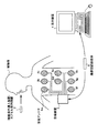
まず、実施の形態1にかかる被検体内導入システムについて説明する。図1は、本実施の形態1にかかる被検体内導入システムの全体構成を示す模式図である。図1に示すように、本実施の形態1にかかる被検体内導入システムは、被検体1の内部に導入されて通過経路に沿って移動するカプセル型内視鏡2と、カプセル型内視鏡2から送信された、被検体内情報を含む無線信号を受信する受信装置3と、受信装置3によって受信された無線信号に含まれる被検体内情報の内容を表示する表示装置4と、受信装置3と表示装置4との間の情報の受け渡しを行うための携帯型記録媒体5とを備える。
(Embodiment 1)
First, the in-subject introduction system according to the first embodiment will be described. FIG. 1 is a schematic diagram illustrating an overall configuration of the in-subject introduction system according to the first embodiment. As shown in FIG. 1, the in-subject introduction system according to the first embodiment includes a
表示装置4は、受信装置3によって受信された、カプセル型内視鏡2によって撮像された被検体内画像等を表示するためのものであり、携帯型記録媒体5によって得られるデータに基づいて画像表示を行うワークステーション等のような構成を有する。具体的には、表示装置4は、CRTディスプレイ、液晶ディスプレイ等によって直接画像等を表示する構成としても良いし、プリンタ等のように、他の媒体に画像等を出力する構成としても良い。
The display device 4 is for displaying an in-vivo image captured by the
携帯型記録媒体5は、受信装置3および表示装置4に対して着脱可能であって、両者に対する装着時に情報の出力および記録が可能な構造を有する。具体的には、携帯型記録媒体5は、カプセル型内視鏡2が被検体1の体腔内を移動している間は受信装置3に装着されて被検体内画像を記憶する。そして、カプセル型内視鏡2が被検体1から排出された後に、受信装置3から取り出されて表示装置4に装着され、記録したデータが表示装置4によって読み出される構成を有する。受信装置3と表示装置4との間のデータの受け渡しをコンパクトフラッシュ(登録商標)メモリ等の携帯型記録媒体5によって行うことで、受信装置3と表示装置4との間が有線接続された場合と異なり、カプセル型内視鏡2が被検体1内部を移動中であっても、被検体1が自由に行動することが可能となる。
The
受信アンテナ6a〜6hは、例えばループアンテナを用いて形成される。かかるループアンテナは、被検体1の体表面の所定の位置に固定された状態で使用され、受信アンテナ6a〜6hは、好ましくはループアンテナを被検体1の体表面に固定するための固定手段を備える。
The
受信装置3は、受信アンテナ6a〜6hのいずれかを介して受信された無線信号の受信処理を行うためのものである。図2は、受信装置3の構成を示すブロック図である。図2に示すように、受信装置3は、複数存在する受信アンテナ6a〜6hの中から無線信号の受信に適したものを選択するアンテナ選択部9と、アンテナ選択部9によって選択された受信アンテナ6を介して受信された無線信号に対して復調等の処理を行う受信回路10と、処理が施された無線信号に対して検出磁場に関する情報および被検体内画像等を抽出するための信号処理部11とを備える。また、受信装置3は、抽出された情報の出力等に関して所定の制御を行う制御部12と、抽出した情報を記憶する記憶部13と、受信回路10から出力された、受信した無線信号の強度に対応したアナログ信号をA/D変換するA/D変換部14と、各構成要素の駆動電力を供給する電力供給部15とを備える。
The receiving
アンテナ選択部9は、複数備わる受信アンテナ6a〜6hの中から無線信号の受信に適したアンテナを選択するためのものである。具体的には、アンテナ選択部9は、制御部12の制御に基づいて所定の受信アンテナ6を選択し、選択した受信アンテナ6を介して受信された無線信号を受信回路10に対して出力する機能を有する。
The antenna selection unit 9 is for selecting an antenna suitable for receiving a radio signal from among a plurality of
受信回路10は、選択された受信アンテナ6を介して受信された無線信号に対して、復調等の所定の処理を行うためのものである。また、受信回路10は、無線信号の強度に対応したアナログ信号をA/D変換部14に対して出力する機能を有する。
The receiving
信号処理部11は、受信回路10によって所定の処理が施された信号の中から所定の情報を抽出するためのものである。例えば、受信装置3によって受信される無線信号が撮像機能を有する電子機器から送信される場合には、信号処理部11は、受信回路10から出力された信号の中から画像データを抽出している。
The
制御部12は、アンテナ選択部9によるアンテナ選択動作を含む全体的な制御を行うためのものである。具体的には、制御部12は、信号処理部11から出力された情報を記憶部13に転送して記憶させると共に、A/D変換部14から出力された、受信強度に対応したディジタル信号(例えば、RSSI(Received Signal Strength Indicator :受信信号強度表示信号))に基づいて、使用する受信アンテナ6を決定し、アンテナ選択部9に対して指示する機能を有する。
The
記憶部13は、信号処理部11によって抽出された情報を記憶するためのものである。記憶部13の具体的構成としては、メモリ等を備えることによって記憶部13自体が情報を記憶することとしても良いが、本実施の形態1では、記憶部13は、携帯型記録媒体5に対して情報を書き込む機能を有することとする。
The
次に、カプセル型内視鏡2について説明する。カプセル型内視鏡2は、特許請求の範囲における被検体内導入装置の一例として機能するものであって、被検体1内部の画像データを取得し、取得した画像データを含む無線信号を受信装置3に対して送信するためのものである。
Next, the
図3は、カプセル型内視鏡2の具体的な構成を示す模式的な断面図である。図3に示すように、カプセル型内視鏡2は、外部形状を規定する外装ケース部材17の内部の所定の位置に固定された撮像基板18と、撮像基板18の一方の面(第1面)上に配置された第1撮像機構19と、撮像基板18の他方の面(第2面)上に配置された第2撮像機構20と、第1撮像機構19近傍に配置された第1照明基板21上に配置された第1照明部22と、第2撮像機構20の近傍に配置された第2照明基板23上に配置された第2照明部24とを備える。さらにカプセル型内視鏡2は、それぞれ撮像基板18上に、第1撮像機構19および第2撮像機構20によって得られた電気信号に基づいて画像データを生成するデータ生成部27と、少なくとも第1撮像機構19、第2撮像機構20およびデータ生成部27の駆動タイミング等を制御するタイミング制御部28と、これらの構成要素を電気的に接続するための配線構造29とを備える。また、カプセル型内視鏡2は、データ生成部27によって取得された画像データを含む無線信号を送信する送信部25と、配線構造29を介して第1撮像機構19等に対して駆動電力を供給する電源部26とを備える。
FIG. 3 is a schematic cross-sectional view showing a specific configuration of the
送信部25は、受信装置3に対して無線信号を送信するためのものである。具体的には、送信部25は、外装ケース部材17内の所定の位置に配置され、変調処理等を行うのに必要な電子回路が形成された送信基板25aと、送信基板25a上に形成された電子回路による処理が施された信号を送信する送信アンテナ25bとを備える。
The
電源部26は、第1撮像機構19等のカプセル型内視鏡2の構成要素に対して駆動電力を供給するためのものである。具体的には、電源部26は、電極構造を含む必要な電子回路が形成された電源基板26aと、電源基板26a上に配置され、電源基板26a上に形成された電極構造と電気的に接続された蓄電池26bとを備える。
The
撮像基板18は、第1撮像機構19、第2撮像機構20等の構成要素を支持するためのものである。具体的には、撮像基板18の第1面上には第1撮像機構19が配置され、第1面と対向する面である第2面上には第2撮像機構20が配置され、第1面または第2面のいずれか一方の面上にデータ生成部27およびタイミング制御部28が配置された構成を有する。そして、これらの構成要素が同一基板上に形成されたことに付随して、各構成要素間を電気的に接続するための配線構造29が撮像基板18上に形成されている。なお、配線構造29は、撮像基板18の表面上にプリントされたプリント配線29aのみならず、撮像基板18の第1面と第2面との間を電気的に接続するスルーホール29bをも含む概念である。
The imaging substrate 18 is for supporting components such as the
第1撮像機構19は、外装ケース部材17に形成された撮像窓17aを経由して入力される外部光を電気信号に変換するためのものである。具体的には、第1撮像機構19は、光電変換素子として機能する第1撮像素子19aと、撮像窓17aを介して入力された外部光を第1撮像素子19aの受光面上に結像させる機能を有する第1光学系19bと、第1光学系19bを保持するためのホルダ部材19cとを備える。
The
第1撮像素子19aは、所定の受光面に入力された入力光の強度に応じた電気信号を出力する機能を有し、特許請求の範囲における第1光電変換手段の一例として機能するものである。具体的には、第1撮像素子19aは、例えばCCD(Charge Coupled Device)によって形成され、所定の受光面上に行列状に配置されたフォトダイオード等の光電変換素子を備えた構成を有する。なお、本実施の形態1において、第1撮像素子19aは、撮像基板18の第1面と接触する部分に所定の電気的な接続端子(図示省略)を有し、かかる接続端子を介して撮像基板18に形成された配線構造29と電気的に接続した構造を有する。 The first image sensor 19a has a function of outputting an electrical signal corresponding to the intensity of input light input to a predetermined light receiving surface, and functions as an example of the first photoelectric conversion means in the claims. . Specifically, the first imaging element 19a is formed by, for example, a CCD (Charge Coupled Device) and has a configuration including photoelectric conversion elements such as photodiodes arranged in a matrix on a predetermined light receiving surface. In the first embodiment, the first image sensor 19a has a predetermined electrical connection terminal (not shown) at a portion in contact with the first surface of the imaging substrate 18, and images are taken via the connection terminal. It has a structure electrically connected to the wiring structure 29 formed on the substrate 18.
第1光学系19bは、撮像窓17aを介して入力される外部光を、第1撮像素子19aの受光面上に結像させるためのものである。なお、図3の例では、第1光学系19bは単レンズによって形成されているが、かかる構成に限定して解釈する必要はなく、複数のレンズを組み合わせた構成としても良いし、結像機能を有する他の機構を備えた構成としても良い。 The first optical system 19b is for imaging external light input through the imaging window 17a on the light receiving surface of the first imaging element 19a. In the example of FIG. 3, the first optical system 19b is formed by a single lens. However, the first optical system 19b need not be interpreted as being limited to such a configuration, and may have a configuration in which a plurality of lenses are combined. It is good also as a structure provided with the other mechanism which has these.
第2撮像機構20は、外装ケース部材17に形成された撮像窓17bを介して入力される外部光を電気信号に変換するためのものである。具体的には、第2撮像機構20は、第1撮像機構19と同様に、第2撮像素子20aと、第2光学系20bと、第2光学系20bを保持するホルダ部材20cとを備える。第2撮像素子20aは、第1撮像素子19aと同様にCCD等によって構成されており、撮像基板18の第2面との接触部分に所定の接続端子を備えた構成を有する。また、第2光学系20bは第1光学系19bと同様の構成を有し、ホルダ部材20cはホルダ部材19cと同様の構成を有することから、ここでは説明を省略する。
The
第1照明部22および第2照明部24は、それぞれ第1撮像機構19および第2撮像機構20による撮像動作の際に、それぞれ撮像対象たる被検体内組織を照射する照明光を出力するためのものである。具体的には、第1照明部22および第2照明部24は、例えばLED(Light Emitting Diode)等によって形成され、それぞれ第1撮像機構19および第2撮像機構20の撮像動作と同期したタイミングで照明光を照射する機能を有する。
The first illuminating
タイミング制御部28は、少なくとも第1撮像機構19等の撮像基板18上に形成された構成要素の動作タイミングを制御するためのものである。具体的には、タイミング制御部28は、例えば駆動タイミングの基準となるパルス信号を生成するタイミングジェネレータを内蔵すると共に、基準パルス信号に基づいた制御信号を各構成要素に対して出力する機能を有する。
The
次に、カプセル型内視鏡2に備わる各構成要素間の接続関係について説明する。図4は、カプセル型内視鏡2に備わる各構成要素間の接続関係を示すブロック図である。図4に示すように、カプセル型内視鏡2は、各構成要素に対して電源部26によって駆動電力が供給される構成を有すると共に、タイミング制御部28が第1撮像機構19、第2撮像機構20、第1照明部22、第2照明部24、セレクタ30(後述)およびデータ生成部27の駆動タイミングを制御する構成を有する。そして、第1撮像機構19および第2撮像機構20によって得られた電気信号はセレクタ30を経由する際にいずれか一方のみが選択され、選択された電気信号がデータ生成部27に出力されて画像データが生成される。データ生成部27によって生成された画像データは、送信部25に出力され、必要に応じて変調処理等が施された上で受信装置3に向けて送信される。
Next, the connection relationship between each component provided in the
セレクタ30は、第1撮像機構19および第2撮像機構20から出力された電気信号のうちいずれか一方を選択してデータ生成部27に出力するためのものである。図3においては図示を省略したが、セレクタ30についても撮像基板18上に形成されるものとする。なお、図4ではデータ生成部27とセレクタ30とを別個独立の構成要素として示しているが、例えばデータ選択機能を有するデータ生成部によって代用することとしても良い。
The
かかる構成要素間の接続関係のうち、画像データ生成に用いられる構成要素、すなわち第1撮像機構19、第2撮像機構20、第1照明部22、第2照明部24、セレクタ30、データ生成部27およびタイミング制御部28の相互間の接続は、撮像基板18上に形成された配線構造29によって行われる。すなわち、図4に示す接続構造のうち、送信部25に対する出力配線以外の接続構造についてはいずれも撮像基板18上の配線構造によって形成されることとなる。
Among the connection relationships between the components, the components used for image data generation, that is, the
次に、本実施の形態1にかかる被検体内導入システムの利点について説明する。本実施の形態1においては、上記したようにカプセル型内視鏡2において、第1撮像機構19と第2撮像機構20とがいずれも単一の撮像基板18上に配置された構成を有する。このため、それぞれを別基板上に配置した場合と比較してカプセル型内視鏡2内に備える基板の数を低減できるという利点を有する。
Next, advantages of the in-subject introduction system according to the first embodiment will be described. In the first embodiment, as described above, the
また、本実施の形態1では撮像基板18の第1面上に第1撮像機構19を配置し、第1面と異なる面である第2面上に第2撮像機構20を配置する構成を採用している。かかる構成を採用することによって、第1撮像機構19の撮像視野と、第2撮像機構20の撮像視野とは互いに異なるものとなり、幅広い範囲の被検体内画像を取得できるという利点を有する。
In the first embodiment, a configuration in which the
また、第1撮像機構19と第2撮像機構20、さらにはデータ生成部27等の画像データの生成に関わる構成要素に関していずれも撮像基板18上に配置することとしている。従って、各構成要素間を電気的に接続する配線構造についても撮像基板18上に形成した配線構造29によって行うことが可能であることから、カプセル型内視鏡2内部における配線構造の占有領域を低減することが可能である。特に、本実施の形態1のように複数の撮像機構を備えることとした場合には、撮像機構からデータ生成部27に向かう配線構造の本数は、撮像機構の増加数だけ増加することになる。従って、データ生成部27が撮像機構と別個の基板上に配置された場合には、単一の撮像機構を備えた場合と比較して基板間接続に用いられる配線構造の本数が増加し、配線構造の占有領域がさらに増加することになる。これに対して、本実施の形態1では、第1撮像機構19および第2撮像機構20とデータ生成部27との間をプリント配線29a等によって接続することが可能であるため、撮像機構の数が増加した場合であっても、カプセル型内視鏡2の内部空間領域における配線構造の占有領域が増加することがなく、カプセル型内視鏡2の大型化を防止することが可能である。
In addition, the
(変形例)
次に、実施の形態1にかかる被検体内導入システムの変形例について説明する。本変形例では、カプセル型内視鏡に備わる第1照明基板および第2照明基板に関して、カプセル型内視鏡の外装ケース部材の内面形状にあわせた湾曲形状を有するよう構成している。
(Modification)
Next, a modification of the in-subject introduction system according to the first embodiment will be described. In this modification, the first illumination substrate and the second illumination substrate provided in the capsule endoscope are configured to have a curved shape that matches the inner surface shape of the exterior case member of the capsule endoscope.
図5は、本変形例における第1照明基板および第2照明基板の構成を示す模式図である。図5に示すように、カプセル型内視鏡に備わる第1照明基板32および第2照明基板33は、それぞれ外装ケース部材17の内面形状に合わせて湾曲し、第1撮像機構19および第2撮像機構20に外部からの光を入射させるための開口部34、35が形成された構造を有する第1照明基板32および第2照明基板33とを備える。そして、第1照明基板32および第2照明基板33は、外装ケース部材17の内面にほぼ接触する状態で配置されている。
FIG. 5 is a schematic diagram showing the configuration of the first illumination board and the second illumination board in the present modification. As shown in FIG. 5, the first illumination board 32 and the second illumination board 33 provided in the capsule endoscope are curved in accordance with the inner surface shape of the exterior case member 17, respectively, and the
一般に、カプセル型内視鏡の外装ケース部材17は、円筒形状の部材の両底部に半球殻形状のドーム部材が固着した形状を有しており、図3を参照すると明らかなように、第1照明部22および第2照明部24は、円筒形状の部分に配置されている。このため、本変形例では、第1照明部22および第2照明部24をそれぞれ保持する第1照明基板32および第2照明基板33の形状を、外装ケース部材17の内面形状に合わせて半円筒形状としている。なお、かかる形状を実現するために、第1照明基板32および第2照明基板33は、可撓性を有するフレキシブル基板を用いて形成することとしても良い。
In general, the outer case member 17 of the capsule endoscope has a shape in which hemispherical dome members are fixed to both bottom portions of a cylindrical member. As is apparent from FIG. The
かかる構成を採用することによって、第1照明基板32等以外の構成要素を配置する領域を充分に確保することが可能である。すなわち、外装ケース部材17の内面形状に合わせた湾曲形状を備えることによって第1照明基板32、第2照明基板33のそれぞれと外装ケース部材17との間の隙間領域を低減することが可能である一方、第1照明基板32等の内面(外装ケース部材17と向き合う面と対向する面)には他の構成要素を配置するための領域が十分確保されることとなる。 By adopting such a configuration, it is possible to secure a sufficient area for arranging components other than the first illumination board 32 and the like. That is, by providing a curved shape that matches the shape of the inner surface of the exterior case member 17, it is possible to reduce the gap region between each of the first illumination substrate 32 and the second illumination substrate 33 and the exterior case member 17. On the other hand, a sufficient area for arranging other components is secured on the inner surface of the first illumination board 32 and the like (the surface facing the surface facing the exterior case member 17).
なお、例えば第1照明基板32および第2照明基板33のそれぞれに、第1照明部22および第2照明部24のそれぞれを収容する凹部を形成することとしても良い。かかる構成を採用することによって、第1照明部22等に起因して生じる突起の程度を低減または解消することが可能となり、第1照明基板32等と外装ケース部材17との間の空隙領域をさらに低減することが可能となるという利点を有することになる。
For example, the first illumination board 32 and the second illumination board 33 may be formed with recesses for accommodating the
(実施の形態2)
次に、実施の形態2にかかる被検体内導入システムについて説明する。本実施の形態2にかかる被検体内導入システムは、カプセル型内視鏡に備わる撮像基板が所定の屈曲部分を有し、かかる屈曲部分によって撮像基板の断面形状がコの字形状となるよう形成された構成を有する。
(Embodiment 2)
Next, the in-subject introduction system according to the second embodiment will be described. In the intra-subject introduction system according to the second embodiment, the imaging substrate provided in the capsule endoscope has a predetermined bent portion, and the cross-sectional shape of the imaging substrate is formed in a U shape by the bent portion. It has the structure made.
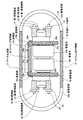
図6は、本実施の形態2にかかる被検体内導入システムに備わるカプセル型内視鏡37の構造を模式的に示す断面図である。なお、本実施の形態2にかかる被検体内導入システムは、図示を省略するものの実施の形態1と同様に受信装置3、表示装置4、携帯型記録媒体5および受信アンテナ6a〜6hを備えることとし、図6に示す構成要素のうち実施の形態1と同様の名称・符号を有するものについては、以下で特に言及しない限り実施の形態1における構成要素と同じ構造・機能を有するものとする。
FIG. 6 is a cross-sectional view schematically showing the structure of the capsule endoscope 37 provided in the in-subject introduction system according to the second embodiment. The in-subject introduction system according to the second embodiment includes the receiving
図6に示すように、カプセル型内視鏡37は、外形を規定する外装ケース部材38内に所定の屈曲部39a、39bにおいて屈曲することによってコの字状に形成された撮像基板39を備える。そして、撮像基板39においてコの字形状によって形成される凸部側の面(外面)上に第1撮像機構19、第2撮像機構20、データ生成部27、タイミング制御部28および送信部40が配置されている。また、撮像基板39においてコの字形状によって形成される凹部側の面(内面)によって形成される空間領域に、直列接続状態の蓄電池26b、26c(特許請求の範囲における電力供給手段の一例に相当)が、一方の陰極および他方の陽極が撮像基板39の凹部側の面上に形成された接続電極と接触するよう配置されている。
As shown in FIG. 6, the capsule endoscope 37 includes an imaging substrate 39 formed in a U shape by bending at predetermined bent portions 39 a and 39 b in an outer case member 38 that defines an outer shape. . Then, the
第1撮像機構19および第2撮像機構20は、それぞれカプセル型内視鏡37の進行方向(すなわち、外装ケース部材38の長手方向)前方および後方と光学系の光軸が一致するよう配置され、外装ケース部材38には、第1撮像機構19および第2撮像機構20の撮像視野に対応して撮像窓38a、38bがそれぞれ形成されている。なお、第1撮像機構19、第2撮像機構20、データ生成部27およびタイミング制御部28の個々の電気的な特性は実施の形態1と同様であり、各構成要素間は実施の形態1と同様にプリント配線29aおよびスルーホール29b等の配線構造29によって電気的に接続されている。なお、屈曲部を有する構成を実現するために、撮像基板39は、フレキシブル基板もしくはリジット・フレキシブル混成基板によって形成するか、少なくとも屈曲部39a、39bに対応した領域が折り曲げ容易なフレキシブル基板によって形成されていることが好ましい。
The
次に、本実施の形態2にかかる被検体内導入システムの利点について説明する。まず、本実施の形態2にかかる被検体内導入システムでは、実施の形態1と同様に第1撮像機構19および第2撮像機構20の双方が単一の撮像基板39上に配置されており、基板数を低減できる等の利点を享受することができる。
Next, advantages of the in-subject introduction system according to the second embodiment will be described. First, in the intra-subject introduction system according to the second embodiment, both the
また、本実施の形態2にかかる被検体内導入システムは、カプセル型内視鏡37に備わる撮像基板39が屈曲部39a、39bを備えることによって、断面がコの字形状となるよう形成されている。このため、第1撮像機構19および第2撮像機構20の撮像視野が外装ケース部材38の長手方向を含む場合であっても、同一の撮像基板39上に配置することが可能であるという利点を有する。すなわち、実施の形態1と同様に、屈曲部を有さない板状の基板の表面と裏面とにそれぞれ第1撮像機構19および第2撮像機構20を配置した場合には、撮像視野を遮ることを回避するために他の構成要素、例えば蓄電池26b、26cを第1撮像機構19等に対して外装ケース部材38の短手方向に配置する必要があり、カプセル型内視鏡37が大型化するという問題が生じる。これに対して、本実施の形態2にかかる被検体内導入システムでは、カプセル型内視鏡37に備わる撮像基板39の断面がコの字形状となるよう形成されることとし、蓄電池26b、26cをコの字形状の凹部側に配置することとしたため、第1撮像機構19および第2撮像機構20の撮像視野が外装ケース部材38の長手方向を含む構成であるにも関わらず、カプセル型内視鏡37が大型化することを回避できるという利点を有する。
In addition, the in-subject introduction system according to the second embodiment is formed such that the imaging substrate 39 provided in the capsule endoscope 37 includes the bent portions 39a and 39b so that the cross section has a U shape. Yes. For this reason, even if it is a case where the imaging visual field of the
1 被検体
2 カプセル型内視鏡
3 受信装置
4 表示装置
5 携帯型記録媒体
6a〜6h 受信アンテナ
9 アンテナ選択部
10 受信回路
11 信号処理部
12 制御部
13 記憶部
14 変換部
15 電力供給部
17 外装ケース部材
17a 撮像窓
17b 撮像窓
18 撮像基板
19 第1撮像機構
19a 第1撮像素子
19b 第1光学系
19c ホルダ部材
20 第2撮像機構
20a 第2撮像素子
20b 第2光学系
20c ホルダ部材
21 第1照明基板
22 第1照明部
23 第2照明基板
24 第2照明部
25 送信部
25a 送信基板
25b 送信アンテナ
26 電源部
26a 電源基板
26b、26c 蓄電池
27 データ生成部
28 タイミング制御部
29 配線構造
29a プリント配線
29b スルーホール
30 セレクタ
32 第1照明基板
33 第2照明基板
34、35 開口部
37 カプセル型内視鏡
38 外装ケース部材
38a、38b 撮像窓
39a、39b 屈曲部
39 撮像基板
40 送信部
DESCRIPTION OF SYMBOLS 1
Claims (8)
当該被検体内導入装置の外形を規定する外装ケース部材と、
前記外装ケース部材内に配置された撮像基板と、
前記撮像基板の一部領域上に配置され、第1光学系および該第1光学系を介して入力された光を光電変換する第1光電変換手段とを有する第1撮像機構と、
前記撮像基板の他の領域上に配置され、第2光学系および該第2光学系を介して入力された光を光電変換する第2光電変換手段とを有する第2撮像機構と、
を備えたことを特徴とする被検体内導入装置。 An in-subject introduction device that is introduced into a subject and captures an image inside the subject,
An exterior case member that defines the outer shape of the in-subject introduction device;
An imaging substrate disposed in the exterior case member;
A first imaging mechanism that is disposed on a partial region of the imaging substrate and includes a first optical system and first photoelectric conversion means that photoelectrically converts light input through the first optical system;
A second imaging mechanism that is disposed on another region of the imaging substrate and includes a second optical system and second photoelectric conversion means that photoelectrically converts light input through the second optical system;
An intra-subject introduction apparatus characterized by comprising:
前記第1光電変換手段、前記第2光電変換手段及び前記データ生成手段は、前記コの字形状の凸部側の面上に配置され、
前記コの字形状の凹部側の面上に配置された電力供給手段をさらに備えたことを特徴とする請求項5に記載の被検体内導入装置。 The imaging substrate has a U-shaped cross section by bending at a plurality of the bent portions,
The first photoelectric conversion unit, the second photoelectric conversion unit, and the data generation unit are disposed on a surface on the convex side of the U-shape,
The in-subject introduction apparatus according to claim 5, further comprising power supply means disposed on a surface of the U-shaped concave portion side.
前記第1照明基板上に配置され、前記第1撮像機構の撮像動作に同期して照明光を出力する第1照明手段と、
前記外装ケース部材の内面形状にあわせて湾曲した形状を有し、前記第2撮像機構の近傍に配置された第2照明基板と、
前記第2照明基板上に配置され、前記第2撮像機構の撮像動作に同期して照明光を出力する第2照明手段と、
をさらに備えたことを特徴とする請求項1〜6のいずれか一つに記載の被検体内導入装置。 A first illumination board having a shape curved in accordance with the inner surface shape of the exterior case member, and disposed in the vicinity of the first imaging mechanism;
First illumination means disposed on the first illumination substrate and outputting illumination light in synchronization with an imaging operation of the first imaging mechanism;
A second illumination board having a curved shape in accordance with the inner surface shape of the exterior case member, and disposed in the vicinity of the second imaging mechanism;
Second illumination means arranged on the second illumination substrate and outputting illumination light in synchronization with an imaging operation of the second imaging mechanism;
The in-subject introduction device according to claim 1, further comprising:
前記被検体内導入装置は、
当該被検体内導入装置の外部形状を規定する外装ケース部材と、
前記外装ケース部材内に配置された撮像基板と、
前記撮像基板の一部領域上に配置され、第1光学系および該第1光学系を介して入力された光を光電変換する第1光電変換手段とを有する第1撮像機構と、
前記撮像基板の他の領域上に配置され、第2光学系および該第2光学系を介して入力された光を光電変換する第2光電変換手段とを有する第2撮像機構と、
前記第1撮像機構および前記第2撮像機構によって撮像された画像情報を含む無線信号を送信する送信手段と、
を備え、
前記受信装置は、
受信アンテナによって受信された無線信号に対して所定の受信処理を行う受信回路と、
前記受信回路によって受信処理された信号から画像情報を抽出する信号処理手段と、
を備えたことを特徴とする被検体内導入システム。 Intra-subject introduction device that introduces an image inside the subject and transmits a radio signal including information on the captured image, and reception of the radio signal transmitted by the intra-subject introduction device An in-subject introduction system comprising a receiving device for performing
The in-subject introduction device comprises:
An exterior case member that defines the external shape of the in-subject introduction device;
An imaging substrate disposed in the exterior case member;
A first imaging mechanism that is disposed on a partial region of the imaging substrate and includes a first optical system and first photoelectric conversion means that photoelectrically converts light input through the first optical system;
A second imaging mechanism that is disposed on another region of the imaging substrate and includes a second optical system and second photoelectric conversion means that photoelectrically converts light input through the second optical system;
Transmitting means for transmitting a radio signal including image information captured by the first imaging mechanism and the second imaging mechanism;
With
The receiving device is:
A receiving circuit that performs a predetermined receiving process on a radio signal received by the receiving antenna;
Signal processing means for extracting image information from a signal received and processed by the receiving circuit;
Intra-subject introduction system characterized by comprising:
Priority Applications (5)
| Application Number | Priority Date | Filing Date | Title |
|---|---|---|---|
| JP2004201931A JP4578873B2 (en) | 2004-07-08 | 2004-07-08 | Intra-subject introduction apparatus and intra-subject introduction system |
| PCT/JP2005/012419 WO2006006452A1 (en) | 2004-07-08 | 2005-07-05 | Device introduced in subject and in-subject introduction system |
| US11/631,353 US20080021270A1 (en) | 2004-07-08 | 2005-07-05 | Body Insertable Apparatus And Body Insertable Apparatus System |
| CNB2005800220250A CN100490732C (en) | 2004-07-08 | 2005-07-05 | Device introduced in subject and in-subject introduction system |
| EP05765470A EP1769720B1 (en) | 2004-07-08 | 2005-07-05 | Device introducable into a subject |
Applications Claiming Priority (1)
| Application Number | Priority Date | Filing Date | Title |
|---|---|---|---|
| JP2004201931A JP4578873B2 (en) | 2004-07-08 | 2004-07-08 | Intra-subject introduction apparatus and intra-subject introduction system |
Publications (3)
| Publication Number | Publication Date |
|---|---|
| JP2006020852A JP2006020852A (en) | 2006-01-26 |
| JP2006020852A5 JP2006020852A5 (en) | 2007-07-19 |
| JP4578873B2 true JP4578873B2 (en) | 2010-11-10 |
Family
ID=35783796
Family Applications (1)
| Application Number | Title | Priority Date | Filing Date |
|---|---|---|---|
| JP2004201931A Expired - Fee Related JP4578873B2 (en) | 2004-07-08 | 2004-07-08 | Intra-subject introduction apparatus and intra-subject introduction system |
Country Status (5)
| Country | Link |
|---|---|
| US (1) | US20080021270A1 (en) |
| EP (1) | EP1769720B1 (en) |
| JP (1) | JP4578873B2 (en) |
| CN (1) | CN100490732C (en) |
| WO (1) | WO2006006452A1 (en) |
Families Citing this family (23)
| Publication number | Priority date | Publication date | Assignee | Title |
|---|---|---|---|---|
| US8797392B2 (en) | 2005-01-05 | 2014-08-05 | Avantis Medical Sytems, Inc. | Endoscope assembly with a polarizing filter |
| US8872906B2 (en) | 2005-01-05 | 2014-10-28 | Avantis Medical Systems, Inc. | Endoscope assembly with a polarizing filter |
| US8310530B2 (en) | 2006-05-19 | 2012-11-13 | Avantis Medical Systems, Inc. | Device and method for reducing effects of video artifacts |
| US8289381B2 (en) | 2005-01-05 | 2012-10-16 | Avantis Medical Systems, Inc. | Endoscope with an imaging catheter assembly and method of configuring an endoscope |
| US8235887B2 (en) | 2006-01-23 | 2012-08-07 | Avantis Medical Systems, Inc. | Endoscope assembly with retroscope |
| US8182422B2 (en) | 2005-12-13 | 2012-05-22 | Avantis Medical Systems, Inc. | Endoscope having detachable imaging device and method of using |
| JP4695432B2 (en) * | 2005-04-12 | 2011-06-08 | オリンパスメディカルシステムズ株式会社 | In-subject introduction apparatus, in-subject information display apparatus, and in-subject information acquisition system |
| US8287446B2 (en) | 2006-04-18 | 2012-10-16 | Avantis Medical Systems, Inc. | Vibratory device, endoscope having such a device, method for configuring an endoscope, and method of reducing looping of an endoscope |
| US7967745B2 (en) * | 2006-09-28 | 2011-06-28 | Given Imaging, Ltd. | In vivo imaging device and method of manufacture thereof |
| JP5025720B2 (en) * | 2007-02-22 | 2012-09-12 | オリンパスメディカルシステムズ株式会社 | Intra-subject introduction system |
| US8064666B2 (en) | 2007-04-10 | 2011-11-22 | Avantis Medical Systems, Inc. | Method and device for examining or imaging an interior surface of a cavity |
| JP5265139B2 (en) | 2007-06-13 | 2013-08-14 | オリンパスメディカルシステムズ株式会社 | In-vivo image acquisition system |
| CN101480334B (en) * | 2008-01-10 | 2011-12-28 | 清华大学 | Full visual acquisition system for organism in body cavity |
| JP5112108B2 (en) * | 2008-02-18 | 2013-01-09 | 株式会社アールエフ | Capsule type endoscope camera and endoscope system |
| JP5248911B2 (en) * | 2008-05-09 | 2013-07-31 | オリンパスメディカルシステムズ株式会社 | Capsule medical device |
| JP5269532B2 (en) | 2008-09-22 | 2013-08-21 | オリンパスメディカルシステムズ株式会社 | Capsule medical device |
| US8532349B2 (en) * | 2010-02-02 | 2013-09-10 | Omnivision Technologies, Inc. | Encapsulated image acquisition devices having on-board data storage, and systems, kits, and methods therefor |
| JP5913870B2 (en) | 2011-08-31 | 2016-04-27 | オリンパス株式会社 | Capsule medical device |
| JP2014023774A (en) * | 2012-07-27 | 2014-02-06 | Olympus Corp | Biological information acquisition system |
| TW201427633A (en) * | 2013-01-14 | 2014-07-16 | Bruce Zheng-San Chou | Endoscopic image capture system and method thereof |
| JP6329496B2 (en) * | 2015-02-06 | 2018-05-23 | オリンパス株式会社 | Battery assembly structure and capsule medical device |
| CN109068951A (en) | 2016-02-24 | 2018-12-21 | 安多卓思公司 | For using the circuit board assemblies of more observation element endoscopes of cmos sensor |
| CN106264427B (en) * | 2016-08-04 | 2018-03-16 | 北京千安哲信息技术有限公司 | Capsule endoscope and its control device, system and detection method |
Citations (3)
| Publication number | Priority date | Publication date | Assignee | Title |
|---|---|---|---|---|
| JP2001231744A (en) * | 2000-02-21 | 2001-08-28 | Asahi Optical Co Ltd | Capsule endoscope |
| JP2003070728A (en) * | 2001-06-20 | 2003-03-11 | Olympus Optical Co Ltd | Capsule type endoscope |
| JP2004121843A (en) * | 2002-09-30 | 2004-04-22 | Given Imaging Ltd | System including optical head assembly, and dome, and in vivo imaging device |
Family Cites Families (9)
| Publication number | Priority date | Publication date | Assignee | Title |
|---|---|---|---|---|
| IL134017A (en) | 2000-01-13 | 2008-04-13 | Capsule View Inc | Camera for viewing inside intestines |
| IL163684A0 (en) * | 2000-05-31 | 2005-12-18 | Given Imaging Ltd | Measurement of electrical characteristics of tissue |
| WO2002054932A2 (en) * | 2001-01-16 | 2002-07-18 | Given Imaging Ltd. | System and method for wide field imaging of body lumens |
| ATE404114T1 (en) * | 2001-06-18 | 2008-08-15 | Given Imaging Ltd | SWALLOWABLE IN-VIVO CAPSULE WITH A CIRCUIT BOARD HAVING RIGID AND FLEXIBLE SECTIONS |
| DE10323216B3 (en) * | 2003-05-22 | 2004-12-23 | Siemens Ag | Endoscope apparatus has cameras which are provided at respective ends of endoscope capsule, such that one of camera is tilted or rotated to change photography range |
| US20050027175A1 (en) * | 2003-07-31 | 2005-02-03 | Zhongping Yang | Implantable biosensor |
| US8702597B2 (en) * | 2003-12-31 | 2014-04-22 | Given Imaging Ltd. | Immobilizable in-vivo imager with moveable focusing mechanism |
| DE602005021052D1 (en) * | 2004-01-19 | 2010-06-17 | Olympus Corp | MEDICAL TREATMENT DEVICE OF CAPSULE TYPE |
| US20060224040A1 (en) * | 2005-03-31 | 2006-10-05 | Given Imaging Ltd. | In vivo imaging device and method of manufacture thereof |
-
2004
- 2004-07-08 JP JP2004201931A patent/JP4578873B2/en not_active Expired - Fee Related
-
2005
- 2005-07-05 CN CNB2005800220250A patent/CN100490732C/en not_active Expired - Fee Related
- 2005-07-05 EP EP05765470A patent/EP1769720B1/en not_active Expired - Fee Related
- 2005-07-05 WO PCT/JP2005/012419 patent/WO2006006452A1/en not_active Application Discontinuation
- 2005-07-05 US US11/631,353 patent/US20080021270A1/en not_active Abandoned
Patent Citations (3)
| Publication number | Priority date | Publication date | Assignee | Title |
|---|---|---|---|---|
| JP2001231744A (en) * | 2000-02-21 | 2001-08-28 | Asahi Optical Co Ltd | Capsule endoscope |
| JP2003070728A (en) * | 2001-06-20 | 2003-03-11 | Olympus Optical Co Ltd | Capsule type endoscope |
| JP2004121843A (en) * | 2002-09-30 | 2004-04-22 | Given Imaging Ltd | System including optical head assembly, and dome, and in vivo imaging device |
Also Published As
| Publication number | Publication date |
|---|---|
| WO2006006452A1 (en) | 2006-01-19 |
| JP2006020852A (en) | 2006-01-26 |
| CN100490732C (en) | 2009-05-27 |
| EP1769720A4 (en) | 2008-10-15 |
| EP1769720A1 (en) | 2007-04-04 |
| CN1976626A (en) | 2007-06-06 |
| EP1769720B1 (en) | 2011-06-15 |
| US20080021270A1 (en) | 2008-01-24 |
Similar Documents
| Publication | Publication Date | Title |
|---|---|---|
| JP4578873B2 (en) | Intra-subject introduction apparatus and intra-subject introduction system | |
| EP1618835B1 (en) | Capsule endoscope and capsule endoscope system | |
| US6939292B2 (en) | Capsule type endoscope | |
| JP4422679B2 (en) | Capsule endoscope and capsule endoscope system | |
| US8038607B2 (en) | Body insertable apparatus with a plurality of imaging blocks | |
| KR100995475B1 (en) | Intra-specimen introducing device | |
| WO2006006382A1 (en) | Introdulcing device into subject and introducing system into subject | |
| JP2006239170A (en) | Detecting device and a manufacturing method of detecting device | |
| EP1749472A1 (en) | Device for acquiring information in examinee | |
| JP4575260B2 (en) | Intra-subject introduction device | |
| JP4526315B2 (en) | Intra-subject introduction apparatus and intra-subject information acquisition system | |
| JP4573585B2 (en) | Intra-subject introduction apparatus and intra-subject introduction system | |
| KR20190113087A (en) | Capsule endoscopy | |
| US20080064330A1 (en) | Receiving Apparatus and Body Insertable System | |
| KR20070023779A (en) | Device for acquiring information in examinee |
Legal Events
| Date | Code | Title | Description |
|---|---|---|---|
| A521 | Request for written amendment filed |
Free format text: JAPANESE INTERMEDIATE CODE: A523 Effective date: 20070531 |
|
| A621 | Written request for application examination |
Free format text: JAPANESE INTERMEDIATE CODE: A621 Effective date: 20070531 |
|
| A131 | Notification of reasons for refusal |
Free format text: JAPANESE INTERMEDIATE CODE: A131 Effective date: 20100518 |
|
| A521 | Request for written amendment filed |
Free format text: JAPANESE INTERMEDIATE CODE: A523 Effective date: 20100716 |
|
| TRDD | Decision of grant or rejection written | ||
| A01 | Written decision to grant a patent or to grant a registration (utility model) |
Free format text: JAPANESE INTERMEDIATE CODE: A01 Effective date: 20100810 |
|
| A01 | Written decision to grant a patent or to grant a registration (utility model) |
Free format text: JAPANESE INTERMEDIATE CODE: A01 |
|
| A61 | First payment of annual fees (during grant procedure) |
Free format text: JAPANESE INTERMEDIATE CODE: A61 Effective date: 20100825 |
|
| FPAY | Renewal fee payment (event date is renewal date of database) |
Free format text: PAYMENT UNTIL: 20130903 Year of fee payment: 3 |
|
| R151 | Written notification of patent or utility model registration |
Ref document number: 4578873 Country of ref document: JP Free format text: JAPANESE INTERMEDIATE CODE: R151 |
|
| FPAY | Renewal fee payment (event date is renewal date of database) |
Free format text: PAYMENT UNTIL: 20130903 Year of fee payment: 3 |
|
| S531 | Written request for registration of change of domicile |
Free format text: JAPANESE INTERMEDIATE CODE: R313531 |
|
| R350 | Written notification of registration of transfer |
Free format text: JAPANESE INTERMEDIATE CODE: R350 |
|
| R250 | Receipt of annual fees |
Free format text: JAPANESE INTERMEDIATE CODE: R250 |
|
| R250 | Receipt of annual fees |
Free format text: JAPANESE INTERMEDIATE CODE: R250 |
|
| R250 | Receipt of annual fees |
Free format text: JAPANESE INTERMEDIATE CODE: R250 |
|
| R250 | Receipt of annual fees |
Free format text: JAPANESE INTERMEDIATE CODE: R250 |
|
| LAPS | Cancellation because of no payment of annual fees |