EP1769720B1 - Device introducable into a subject - Google Patents
Device introducable into a subject Download PDFInfo
- Publication number
- EP1769720B1 EP1769720B1 EP05765470A EP05765470A EP1769720B1 EP 1769720 B1 EP1769720 B1 EP 1769720B1 EP 05765470 A EP05765470 A EP 05765470A EP 05765470 A EP05765470 A EP 05765470A EP 1769720 B1 EP1769720 B1 EP 1769720B1
- Authority
- EP
- European Patent Office
- Prior art keywords
- imaging
- board
- imaging mechanism
- face
- insertable apparatus
- Prior art date
- Legal status (The legal status is an assumption and is not a legal conclusion. Google has not performed a legal analysis and makes no representation as to the accuracy of the status listed.)
- Expired - Fee Related
Links
Images


Classifications
-
- A—HUMAN NECESSITIES
- A61—MEDICAL OR VETERINARY SCIENCE; HYGIENE
- A61B—DIAGNOSIS; SURGERY; IDENTIFICATION
- A61B1/00—Instruments for performing medical examinations of the interior of cavities or tubes of the body by visual or photographical inspection, e.g. endoscopes; Illuminating arrangements therefor
- A61B1/04—Instruments for performing medical examinations of the interior of cavities or tubes of the body by visual or photographical inspection, e.g. endoscopes; Illuminating arrangements therefor combined with photographic or television appliances
- A61B1/05—Instruments for performing medical examinations of the interior of cavities or tubes of the body by visual or photographical inspection, e.g. endoscopes; Illuminating arrangements therefor combined with photographic or television appliances characterised by the image sensor, e.g. camera, being in the distal end portion
- A61B1/051—Details of CCD assembly
-
- A—HUMAN NECESSITIES
- A61—MEDICAL OR VETERINARY SCIENCE; HYGIENE
- A61B—DIAGNOSIS; SURGERY; IDENTIFICATION
- A61B1/00—Instruments for performing medical examinations of the interior of cavities or tubes of the body by visual or photographical inspection, e.g. endoscopes; Illuminating arrangements therefor
- A61B1/00002—Operational features of endoscopes
- A61B1/00011—Operational features of endoscopes characterised by signal transmission
- A61B1/00016—Operational features of endoscopes characterised by signal transmission using wireless means
-
- A—HUMAN NECESSITIES
- A61—MEDICAL OR VETERINARY SCIENCE; HYGIENE
- A61B—DIAGNOSIS; SURGERY; IDENTIFICATION
- A61B1/00—Instruments for performing medical examinations of the interior of cavities or tubes of the body by visual or photographical inspection, e.g. endoscopes; Illuminating arrangements therefor
- A61B1/00163—Optical arrangements
- A61B1/00174—Optical arrangements characterised by the viewing angles
- A61B1/00177—Optical arrangements characterised by the viewing angles for 90 degrees side-viewing
-
- A—HUMAN NECESSITIES
- A61—MEDICAL OR VETERINARY SCIENCE; HYGIENE
- A61B—DIAGNOSIS; SURGERY; IDENTIFICATION
- A61B1/00—Instruments for performing medical examinations of the interior of cavities or tubes of the body by visual or photographical inspection, e.g. endoscopes; Illuminating arrangements therefor
- A61B1/04—Instruments for performing medical examinations of the interior of cavities or tubes of the body by visual or photographical inspection, e.g. endoscopes; Illuminating arrangements therefor combined with photographic or television appliances
- A61B1/041—Capsule endoscopes for imaging
Definitions
- the present invention relates to a body insertable apparatus, which is inserted into a subject and picks up an image inside the subject, and to a body insertable apparatus system.
- the capsule endoscope has an imaging function and a radio transmission function. After being swallowed by a patient, i.e., a subject, from the mouth for an observation (examination), the capsule endoscope travels through inside body cavities, e.g. internal organs such as stomach and small intestine following peristaltic movements and sequentially captures images using the imaging function, according to which intra-subject images are captured at 0.5-second intervals, for example, until naturally discharged from a living body (human body) of the subject.
- body cavities e.g. internal organs such as stomach and small intestine following peristaltic movements and sequentially captures images using the imaging function, according to which intra-subject images are captured at 0.5-second intervals, for example, until naturally discharged from a living body (human body) of the subject.
- the capsule endoscope While the capsule endoscope travels through the internal organs, the capsule endoscope captures images in the body cavities thereby obtaining image data, and sequentially transmits the image data to an outside using the radio communication function.
- the image data is accumulated in a memory provided outside.
- the subject When the subject carries the receiving apparatus equipped with the radio communication function and the memory function, the subject can move freely without inconveniences even after swallowing the capsule endoscope and before discharging the same.
- a doctor or a nurse can display images of the organs on a display unit or the like based on the image data accumulated in the memory, and make diagnosis (see, for example, Patent Document 1).
- an imaging mechanism provided in the capsule endoscope has an optical system for focusing light supplied from outside, and a photoelectric transducer that converts the light focused by the optical system to electric signals.
- the capsule endoscope has a data generator that generates image data based on the electric signals output from the imaging mechanism. A necessary processing such as modulation is performed on the image data generated by the data generator, and the processed image data is radio transmitted to outside.
- the aforementioned capsule endoscope having a plurality of imaging mechanisms is proposed.
- the plurality of imaging mechanisms are provided inside the capsule endoscope to obtain a plurality of image data, in which each image data corresponds to different field of view.
- obtainable information on the body cavity of a patient increases so that the doctor can make diagnosis on the body cavity more accurately.
- Patent Document 1 Japanese Patent Application Laid-open No. 2003-19111
- an encapsulated medical imaging system comprising a capsule of swallowable proportion, comprising at least one optical setup of a number of optical setups comprising an array of microlenses distributed in axial symmetry on at least a portion of the capsule so that the array of microlenses is capable of receiving light reflected from object located in at least a sector outside the capsule, corresponding optical array comprising an array of light sensitive cells optically communicating with said optical setup through focusing means, such that the image of the object is focused on the array of light sensitive cells, electronic circuitry adapted to sample image data obtained by the optical array by scanning the image and converting the image data to digital data, illuminating means for illuminating a sector in front the optical setup, outside the capsule, transmitting means communicating with said electronic circuitry, adapted to receive image digital data and transmit it to an external receiver, receiving means for receiving data transmitted from said capsule
- JP 2003070728 refers to a capsule type endoscope, comprising an imaging element, a lighting element, a battery, an image signal processing circuit, a memory, an image information transmission circuit, and a radio transmission antenna, which are housed in the capsule main body. Signals imaged by the imaging element are processed by the image signal processing circuit to generate image information. The generated image information is once stored in the memory and then transmitted to the outside of the body by radio by the image information transmission circuit.
- a size of the capsule endoscope increases due to an increase in a number of elements provided therein, and a number of wirings electrically connecting the elements increases correspondingly.
- each element housed in the capsule endoscope is arranged on a different board.
- the number of boards housed in the capsule endoscope increases, and inside the capsule endoscope, a region occupied by the boards increases.
- the number of the wirings electrically connecting the boards increases along with the increase in the number of the boards.
- the size of the capsule endoscope increases, and probability of disconnection of the wirings increases along with the increase in the number of the wirings. Therefore, the capsule endoscope having the aforementioned configuration is not appropriate.
- the present invention is provided in view of the foregoing, and an object of the present invention is to realize a body insertable apparatus, which suppresses increase in the number of boards due to increase in the number of elements, and to realize a body insertable apparatus system.
- a body insertable apparatus according to the present invention is defined by the independent claim.
- Preferred embodiments of the body insertable apparatus are defined by the dependent claims.
- a first photoelectric transducer and a second photoelectric transducer are arranged on a same face of the surface of the imaging board. Consequently, a number of boards provided inside an outer casing member can be reduced, and increase in size of the body insertable apparatus can be suppressed.
- FIG. 1 is a general schematic diagram of the body insertable apparatus system according to the first embodiment.
- the body insertable apparatus system according to the first embodiment has an capsule endoscope 2, a receiving device 3, a display device 4, and a portable recording medium 5.
- the capsule endoscope 2 is inserted into a subject 1, and travels along a traveling passage.
- the receiving device 3 receives radio signals, which are transmitted from the capsule endoscope 2 and contain subject interior information.
- the display device 4 displays content on the subject interior information contained in the radio signals received by the receiving device 3.
- the portable recording medium 5 transfers information between the receiving device 3 and the display device 4.
- the display device 4 serves to display a subject interior image and the like picked up by the capsule endoscope 2 and received by the receiving device 3, and the display device 4 has a configuration such as a workstation that displays the image based on data acquired from the portable recording medium 5.
- the display device 4 may have a configuration that directly displays the image through a cathode ray tube (CRT) display, a liquid crystal display, and the like, or may have a configuration that outputs the image to other medium, such as a printer.
- CTR cathode ray tube
- the portable recording medium 5 is detachable with respect to the receiving device 3 and the display device 4, and can record or output the information when the portable recording medium 5 is attached to the receiving device 3 or the display device 4. Specifically, the portable recording medium 5 is attached to the receiving device 3 and records the subject interior image, while the capsule endoscope 2 travels through inside the body cavity of the subject 1. After the capsule endoscope 2 is discharged from the subject 1, the portable recording medium 5 is removed from the receiving device 3, and attached to the display device 4. Then, the display device 4 reads the data recorded on the portable recording medium 5.
- the subject 1 can freely move while the capsule endoscope 2 travels through inside the subject 1, since the data is transferred between the receiving device 3 and the display device 4 through a portable recording medium 5 consisting of a compact flash® memory and the like.
- Receiving antennas 6a to 6h consist of, for example, loop antennas. During their use, the loop antennas are fixed on predetermined positions of a body surface of the subject 1, and the receiving antennas 6a to 6h preferably have securing units for fixing the loop antennas on the body surface of the subject 1.
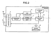
- FIG. 2 is a block diagram of the receiving device 3.
- the receiving device 3 has an antenna selector 9, a receiving circuit 10, and a signal processing unit 11.
- the antenna selector 9 selects a receiving antenna, which is appropriate for receiving the radio signals, from the receiving antennas 6a to 6h.
- the receiving circuit 10 performs a processing such as demodulation on the radio signals received through receiving antenna 6 selected by the antenna selector 9.
- the signal processing unit 11 extracts the subject interior image, information on detected magnetic field, and the like from the radio signals after the processing.
- the receiving device 3 has a control unit 12, a storage unit 13, an A/D (analog/digital) converter 14, and a power supply unit 15.
- the control unit 12 controls the output and the like of the extracted information in a predetermined manner.
- the storage unit 13 stores the extracted information.
- the A/D converter 14 performs an A/D conversion on analog signals supplied from the receiving circuit 10 and corresponding to strength of the received radio signals.
- the power supply unit 15 supplies driving power of the aforementioned elements provided in the receiving device 3.
- the antenna selector 9 serves to select the antenna, which is appropriate for receiving the radio signals, from the receiving antennas 6a to 6h. Specifically, the antenna selector 9 selects the predetermined receiving antenna 6 under the control of the control unit 12, and outputs the radio signals received through the selected receiving antenna 6 to the receiving circuit 10.
- the receiving circuit 10 serves to perform the predetermined processing such as the demodulation on the radio signals received through the selected receiving antenna 6.
- the receiving circuit 10 outputs the analog signals, which correspond to the strength of the radio signals, to the A/D converter 14.
- the signal processing unit 11 serves to extract predetermined information from the signals, on which the predetermined processing is performed by the receiving circuit 10. For example, when the radio signals to be received by the receiving device 3 are transmitted from an electronic device having an imaging function, the signal processing unit 11 extracts the image data from the signals output from the receiving circuit 10.
- the control unit 12 serves to perform a general controlling of operations including an antenna selection operation performed by the antenna selector 9. Specifically, the control unit 12 transfers the information output from the signal processing unit 11 to the storage unit 13, and stores the transferred information in the storage unit 13. Further, the control unit 12 selects the receiving antenna 6 to be used based on digital signals (for example, received signal strength indicator (RSSI)), which are output from the A/D converter 14, corresponding to the receiving strength, and the control unit 12 commands the antenna selector 9 to select the receiving antenna 6.
- RSSI received signal strength indicator
- the storage unit 13 serves to store the information extracted by the signal processing unit 11. Specifically, the storage unit 13 may have a memory and the like that store the information; however, in the first embodiment, the storage unit 13 writes the information into the portable recording medium 5.
- the capsule endoscope 2 is explained.
- the capsule endoscope 2 functions as a body insertable apparatus.
- the capsule endoscope 2 acquires the image data inside the subject 1, and transmits the radio signals containing the acquired image data to the receiving device 3.
- FIG. 3 is a sectional view of a specific configuration of the capsule endoscope 2.
- the capsule endoscope 2 has an imaging board 18, a first imaging mechanism 19, a second imaging mechanism 20, a first illuminating unit 22, and a second illuminating unit 24.
- the imaging board 18 is secured at a predetermined position inside an outer casing member 17 determining an outer shape of the capsule endoscope 2.
- the first imaging mechanism 19 is arranged on one face (first face) of the imaging board 18.
- the second imaging mechanism 20 is arranged on other face (second face) of the imaging board 18.
- the first illuminating unit 22 is arranged on a first illuminating board 21 arranged near the first imaging mechanism 19.
- the second illuminating unit 24 is arranged on a second illuminating board 23 arranged near the second imaging mechanism 20.
- the capsule endoscope 2 has a data generator 27, a timing controller 28, and a wiring configuration 29, and each of the data generator 27, the timing controller 28, and the wiring configuration 29 is arranged on the imaging board 18.
- the data generator 27 generates image data based on electric signals obtained by the first imaging mechanism 19 and the second imaging mechanism 20.
- the timing controller 28 controls driving timings and the like of at least the first imaging mechanism 19, the second imaging mechanism 20, and the data generator 27.
- the wiring configuration 29 electrically connects the aforementioned elements inside the capsule endoscope 2.
- the capsule endoscope 2 has a transmitting unit 25 that transmits the radio signals containing the image data obtained by the data generator 27, and a power unit 26 that supplies driving power to the first imaging mechanism 19 and the like through the wiring configuration 29.
- the transmitting unit 25 serves to transmit the radio signals to the receiving device 3. Specifically, the transmitting unit 25 is arranged at a predetermined position inside the outer casing member 17, and has a transmitting board 25a, on which electronic circuit required to perform modulation and the like is formed, and a transmitting antenna 25b that transmits signals on which the processing is performed by the electronic circuit formed on the transmitting board 25a.
- the power unit 26 serves to supply the driving power to the elements, such as the first imaging mechanism 19, provided inside the capsule endoscope 2.
- the power unit 26 has a power board 26a on which a required electronic circuit including electrodes is formed, and a storage battery 26b arranged on the power board 26a and electrically connected to the electrodes formed on the power board 26a.
- the imaging board 18 serves to support the elements such as the first imaging mechanism 19 and the second imaging mechanism 20.
- the first imaging mechanism 19 is arranged on the first face of the imaging board 18
- the second imaging mechanism 20 is arranged on the second face opposing to the first face
- the data generator 27 and the timing controller 28 are arranged on one of the first face and the second face. Since the elements are arranged on the same board, the wiring configuration 29 that electrically connects the elements is formed on the imaging board 18.
- the wiring configuration 29 includes a through hole 29b that electrically connects the first face and the second face of the imaging board 18 to each other, in addition to a printed wiring configuration 29a formed on a surface of the imaging board 18.
- the first imaging mechanism 19 serves to convert external light coming through an imaging window 17a formed at the outer casing member 17 to electric signals.
- the first imaging mechanism 19 has a first imaging element 19a that functions as a photoelectric transducer, a first optical system 19b that focuses the external light coming through the imaging widow 17a on a light receiving face of the first imaging element 19a, and a holder member 19c that secures the first optical system 19b therein.
- the first imaging element 19a outputs electric signals corresponding to strength of light focused on the predetermined light receiving face, and functions as a first photoelectric transducer.
- the first imaging element 19a consists of a charge coupled device (CCD), and has a photoelectric transducer such as a photodiode arranged in a matrix shape on the predetermined light receiving face.
- the first imaging element 19a has a predetermined electrical connecting terminal (not shown) at a section that is in contact with the first face of the imaging board 18, and the first imaging element 19a is electrically connected to the wiring configuration 29 formed on the imaging board 18 through the connecting terminal.
- the first optical system 19b serves to focus the external light coming through the imaging window 17a on the light receiving face of the first imaging element 19a.
- the first optical system 19b consists of a single lens; however, the present invention is not limited thereto.
- the first optical system 19b may consist of a combination of a plurality of lenses, or may have other mechanism having the focusing function.
- the second imaging mechanism 20 serves to convert the external light coming through an imaging window 17b formed at the outer casing member 17 to electric signals.
- the second imaging mechanism 20 has a second imaging element 20a, a second optical system 20b, and a holder member 20c that secures the second optical system 20b therein.
- the second imaging device 20a consists of a CCD and the like, and has a predetermined connecting terminal at a section that is in contact with the second face of the imaging board 18.
- the second optical system 20b has a configuration similar to the configuration of the first optical system 19b
- the holder member 20c has a configuration that is similar to the configuration of the holder member 19c; therefore, explanations thereof are not to be repeated.
- the first illuminating unit 22 and the second illuminating unit 24 serve to output illuminating light that illuminates tissue, i.e., an imaging object, inside the subject during the imaging operation by the first imaging mechanism 19 and the second imaging mechanism 20.
- the first illuminating unit 22 and the second illuminating unit 24 consist of a light emitting diode (LED) and the like, and the first illuminating unit 22 and the second illuminating unit 24 output the illuminating light with timings in synchronization with the imaging operation of the first imaging mechanism 19 and the second imaging mechanism 20, respectively.
- LED light emitting diode
- the timing controller 28 serves to at least control operation timings of the elements, such as the first imaging mechanism 19, arranged on the imaging board 18.
- the timing controller 28 includes, for example, a timing generator that generates pulse signals, which is reference to the driving timing, and the timing controller 28 outputs controlling signals generated based on the reference pulse signals to each element.
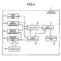
- FIG. 4 is a block diagram of the connection relationships among the elements provided in the capsule endoscope 2.
- the power unit 26 supplies the driving power to each element
- the timing controller 28 Controls the driving timings of the first imaging mechanism 19, the second imaging mechanism 20, the first illuminating unit 22, the second illuminating unit 24, a selector 30 (described later), and the data generator 27.
- the electric signals acquired by one of the first imaging mechanism 19 and the second imaging mechanism 20 are selected when the electric signals passes through the selector 30, and the selected electric signals are output to the data generator 27 to generate the image data.
- the image data generated by the data generator 27 is output to the transmitting unit 25, and the modulation and the like is performed on the output image data, if necessary. Then, the image data is output to the receiving device 3.
- the selector 30 serves to select the electric signals output from one of the first imaging mechanism 19 and the second imaging mechanism 20, and outputs the selected electric signals to the data generator 27.
- the selector 30 is not shown in FIG. 3 , the selector 30 is also arranged on the imaging board 18.
- the data generator 27 and the selector 30 are provided separately from one other; however, for example, a data generator having a data selecting function can replace the data generator 27 and the selector 30.
- the elements used for an image data generation i.e., the first imaging mechanism 19, the second imaging mechanism 20, the first illuminating unit 22, the second illuminating unit 24, the selector 30, the data generator 27, and the timing controller 28, are connected to each other by the wiring configuration 29 formed on the imaging board 18.
- the connections excluding the connection of an output wiring transferring the generated image data to the transmitting unit 25 are formed by the wiring configuration on the imaging board 18.
- the first imaging mechanism 19 and the second imaging mechanism 20 are arranged on the single imaging board 18.
- a number of boards provided in the capsule endoscope 2 can be reduced compared to when the first imaging mechanism 19 and the second imaging mechanism 20 are each arranged on a different board.
- the first imaging mechanism 19 is arranged on the first face of the imaging board 18, and the second imaging mechanism 20 is arranged on the second face that is different from the first face. Since the first embodiment employs the aforementioned configuration, an imaging field of view of the first imaging mechanism 19 differs from an imaging field of view of the second imaging mechanism 20, and a subject interior image associated with a wider range can be obtained.
- the first imaging mechanism 19 and the second imaging mechanism 20, and in addition, the elements, such as the data generator 27, associated with the generation of the image data are each arranged on the imaging board 18. Since the wiring configuration 29 formed on the imaging board 18 electrically connects each element, a region occupied by the wiring configuration provided inside the capsule endoscope 2 can be reduced. Particularly, when the plurality of imaging mechanisms are provided as similar to the first embodiment, the number of the wiring configuration running towards the data generator 27 from the imaging mechanisms increases by the increased number of the imaging mechanisms. When the data generator 27 is arranged on a board that is different from a board on which the imaging mechanisms are arranged, the number of the wiring configuration used to connect the boards is increased compared to when a single imaging mechanism is provided. Thus, the region occupied by the wiring configuration increases.
- the first imaging mechanism 19, the second imaging mechanism 20, the data generator 27 can be connected to each other by printed wiring 29a and the like.
- the region occupied by the wiring configuration inside an interior space region of the capsule endoscope 2 does not increase, and it can be prevented to increase a size of the capsule endoscope 2.
- a modification of a body insertable apparatus system according to the first embodiment is explained.
- a first illuminating board and a second illuminating board provided in the capsule endoscope are curved so as to match with a shape of an inner face of the outer casing member of the capsule endoscope.
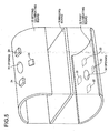
- FIG. 5 is a schematic diagram of the first illuminating board and the second illuminating board according to the modification.
- a first illuminating board 32 and a second illuminating board 33 provided in the capsule endoscope are each curved so as to match with the shape of the inner face of the outer casing member 17, and has the first illuminating board 32 and the second illuminating board 33 having openings 34 and 35, respectively, so that the light from outside enters the first imaging mechanism 19 and the second imaging mechanism 20.
- the first illuminating board 32 and the second illuminating board 33 are arranged so as to substantially contact with the inner face of the outer casing member 17.
- the outer casing member 17 of the capsule endoscope has a shape in which semispherical dorm members are fixed on both ends of a cylindrical member , and it is apparent from FIG. 3 that the first illuminating unit 22 and the second illuminating unit 24 are arranged inside the cylindrical member.
- shapes of the first illuminating board 32 and the second illuminating board 33 having the first illuminating unit 22 and the second illuminating unit 24, respectively have semicylindrical shapes so as to match with the shape of the inner face of the outer casing member 17.
- the first illuminating board 32 and the second illuminating board 33 can be formed with flexible boards having flexibility.
- the capsule endoscope employing the aforementioned configuration, a region, in which the elements other than the first illuminating board 32 and the like are arranged, can sufficiently be obtained. Since the first illuminating board 32 and the second illuminating board 33 have the curved shapes that match with the shape of the inner face of the outer casing member 17, spaces between the outer casing member 17 and each of the first illuminating board 32 and the second illuminating board 33 can be reduced, and the region in which other elements are arranged can sufficiently be obtained on the inner face (a face opposite to a face in front of the outer casing member 17) of the first illuminating board 32 and the like.
- Depressed portions housing the first illuminating unit 22 and the second illuminating unit 24 can be formed on, for example, the first illuminating board 32 and the second illuminating board 33.
- the capsule endoscope employing the aforementioned configuration height of protrusions formed by the first illuminating unit 22 and the like can be reduced or eliminated.
- a space region between the board such as the first illuminating board 32 and the outer casing member 17 can be reduced.
- an imaging board provided in the capsule endoscope has a predetermined bent portion, and the bent portion forms a U-shaped cross section of the imaging board.
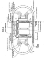
- FIG. 6 is a sectional view of a capsule endoscope 37 provided in the body insertable apparatus system according to the second embodiment.
- the body insertable apparatus system according to the second embodiment has the receiving device 3, the display device 4, the portable recording medium 5, and the receiving antennas 6a to 6h, as similar to the first embodiment.
- elements represented by names, letters, and numerals that are similar to those of the first embodiment have configurations and functions similar to those of the first embodiment as long as not specifically mentioned hereinafter.
- the capsule endoscope 37 has an imaging board 39 that is bent at bent portions 39a and 39b and formed in the U-shape, in an outer casing member 38 that determines an exterior shape of the capsule endoscope 37.
- the imaging board 39 the first imaging mechanism 19, the second imaging mechanism 20, the data generator 27, the timing controller 28, and a transmitting unit 40 are arranged on a face (outer face) of a protruding region side formed by the U-shape.
- batteries 26b and 26c (corresponding to a power supply unit) connected in series are arranged in a space region, which is formed by a face (inner face) of a depressed portion side formed by the U-shape, so that a cathode of one battery and an anode of another battery are in contact with the electrodes, respectively, formed on the face of the depressed portion side of the imaging board 39.
- the first imaging mechanism 19 and the second imaging mechanism 20 are arranged so that optical axes of the optical system match with a traveling direction and a direction opposite to the traveling direction (i.e., longitudinal direction of the outer casing member 38) of the capsule endoscope 37.
- Imaging windows 38a and 38b are formed corresponding to imaging field of views of the first imaging mechanism 19 and the second imaging mechanism 20, respectively, on the outer casing member 38.
- Electrical properties of each of the first imaging mechanism 19, the second imaging mechanism 20, the data generator 27, and the timing controller 28 are the same as the electrical properties explained in the first embodiment, and as similar to the first embodiment, elements are electrically connected to each other by the wiring configuration 29 such as the printed wiring configuration 29a and the through hole 29b.
- the imaging board 39 it is preferred to form the imaging board 39 by a flexible board or a rigid/flexible composite board, or at least regions corresponding to the bent portions 39a and 39b are preferred to be made by a flexible board that can easily be bent.
- both the first imaging mechanism 19 and the second imaging mechanism 20 are arranged on the single imaging board 39, so that an advantage such that the number of the boards can be reduced is obtained.
- the imaging board 39 provided in the capsule endoscope 37 has the bent portions 39a and 39b so that the cross section of the imaging board 39 has U-shape. Therefore, even when the imaging field of views of the first imaging mechanism 19 and the second imaging mechanism 20 extend in the longitudinal direction of the outer casing member 38, the first imaging mechanism 19 and the second imaging mechanism 20 may be arranged on the same imaging board 39.
- the cross section of the imaging board 39 provided in the capsule endoscope 37 has the U-shape, and the batteries 26b and 26c are arranged on the depressed region side of the U-shape. Therefore, even though the imaging field of views of the first imaging mechanism 19 and the second imaging mechanism 20 extend in the longitudinal direction of the outer casing member 38, the increase in the size of the capsule endoscope 37 can be prevented.
- a body insertable apparatus and a body insertable apparatus system are useful for an image capturing process of an image of a subject interior such as a body cavity interior, and appropriate for a body insertable apparatus and a body insertable apparatus system that can suppress increase in size of the body insertable apparatus while having an imaging function for obtaining a plurality of images, each corresponding to a different field of view inside the subject.
Abstract
Description
- The present invention relates to a body insertable apparatus, which is inserted into a subject and picks up an image inside the subject, and to a body insertable apparatus system.
- Recently, a swallowable capsule endoscope has been proposed in a field of endoscopes. The capsule endoscope has an imaging function and a radio transmission function. After being swallowed by a patient, i.e., a subject, from the mouth for an observation (examination), the capsule endoscope travels through inside body cavities, e.g. internal organs such as stomach and small intestine following peristaltic movements and sequentially captures images using the imaging function, according to which intra-subject images are captured at 0.5-second intervals, for example, until naturally discharged from a living body (human body) of the subject.
- While the capsule endoscope travels through the internal organs, the capsule endoscope captures images in the body cavities thereby obtaining image data, and sequentially transmits the image data to an outside using the radio communication function. The image data is accumulated in a memory provided outside. When the subject carries the receiving apparatus equipped with the radio communication function and the memory function, the subject can move freely without inconveniences even after swallowing the capsule endoscope and before discharging the same. After the capsule endoscope is discharged, a doctor or a nurse can display images of the organs on a display unit or the like based on the image data accumulated in the memory, and make diagnosis (see, for example, Patent Document 1).
- Generally, an imaging mechanism provided in the capsule endoscope has an optical system for focusing light supplied from outside, and a photoelectric transducer that converts the light focused by the optical system to electric signals. The capsule endoscope has a data generator that generates image data based on the electric signals output from the imaging mechanism. A necessary processing such as modulation is performed on the image data generated by the data generator, and the processed image data is radio transmitted to outside.
- The aforementioned capsule endoscope having a plurality of imaging mechanisms is proposed. The plurality of imaging mechanisms are provided inside the capsule endoscope to obtain a plurality of image data, in which each image data corresponds to different field of view. Thus, obtainable information on the body cavity of a patient increases so that the doctor can make diagnosis on the body cavity more accurately.
- Patent Document 1: Japanese Patent Application Laid-open No.
2003-19111 -
US 2003/0208107 A1 relates to an encapsulated medical imaging device and a method for imaging the gastrointestinal tract in patients using optical scanning technologies. For this purpose, an encapsulated medical imaging system is provided, comprising a capsule of swallowable proportion, comprising at least one optical setup of a number of optical setups comprising an array of microlenses distributed in axial symmetry on at least a portion of the capsule so that the array of microlenses is capable of receiving light reflected from object located in at least a sector outside the capsule, corresponding optical array comprising an array of light sensitive cells optically communicating with said optical setup through focusing means, such that the image of the object is focused on the array of light sensitive cells, electronic circuitry adapted to sample image data obtained by the optical array by scanning the image and converting the image data to digital data, illuminating means for illuminating a sector in front the optical setup, outside the capsule, transmitting means communicating with said electronic circuitry, adapted to receive image digital data and transmit it to an external receiver, receiving means for receiving data transmitted from said capsule, image processing means for processing the data received by the receiving means, and display means for displaying an image. -
JP 2003070728 - However, when the capsule endoscope comes to have the plurality of imaging mechanisms, a size of the capsule endoscope increases due to an increase in a number of elements provided therein, and a number of wirings electrically connecting the elements increases correspondingly. Normally, each element housed in the capsule endoscope is arranged on a different board. Hence, as the number of elements increases, the number of boards housed in the capsule endoscope increases, and inside the capsule endoscope, a region occupied by the boards increases. Further, it is required to electrically connect the elements with each other. Hence, the number of the wirings electrically connecting the boards increases along with the increase in the number of the boards. As a result, the size of the capsule endoscope increases, and probability of disconnection of the wirings increases along with the increase in the number of the wirings. Therefore, the capsule endoscope having the aforementioned configuration is not appropriate.
- The present invention is provided in view of the foregoing, and an object of the present invention is to realize a body insertable apparatus, which suppresses increase in the number of boards due to increase in the number of elements, and to realize a body insertable apparatus system.
- A body insertable apparatus according to the present invention is defined by the independent claim. Preferred embodiments of the body insertable apparatus are defined by the dependent claims.
- In a body insertable apparatus according to the present invention, a first photoelectric transducer and a second photoelectric transducer are arranged on a same face of the surface of the imaging board. Consequently, a number of boards provided inside an outer casing member can be reduced, and increase in size of the body insertable apparatus can be suppressed.
-
-
FIG. 1 is a general schematic diagram of a body insertable apparatus system according to a first embodiment; -
FIG. 2 is a block diagram of a receiving device provided in the body insertable apparatus system; -
FIG. 3 is a schematic diagram of a configuration of an capsule endoscope provided in the body insertable apparatus system; -
FIG. 4 is a block diagram for explaining connection relationships among elements provided in the capsule endoscope; -
FIG. 5 is a schematic diagram of an illuminating board provided in an capsule endoscope according to a modification; and -
FIG. 6 is a schematic diagram of a configuration of an capsule endoscope provided in a body insertable apparatus system according to a second embodiment. -
- 1
- Subject
- 2
- Capsule endoscope
- 3
- Receiving device
- 4
- Display device
- 5
- Portable recording medium
- 6a-6h
- Receiving antennas
- 9
- Antenna selector
- 10
- Receiving circuit
- 11
- Signal processing unit
- 12
- Control unit
- 13
- Storage unit
- 14
- A/D converter
- 15
- Power supply unit
- 17
- Outer casing member
- 17a
- Imaging window
- 17b
- Imaging window
- 18
- Imaging board
- 19
- First imaging mechanism
- 19a
- First imaging device
- 19b
- First optical system
- 19c
- Holder member
- 20
- Second imaging mechanism
- 20a
- Second imaging device
- 20b
- Second optical system
- 20c
- Holder member
- 21
- First illuminating board
- 22
- First illuminating unit
- 23
- Second illuminating board
- 24
- Second illuminating unit
- 25
- Transmitting unit
- 25a
- Transmitting board
- 25b
- transmitting antenna
- 26
- Power unit
- 26a
- Power board
- 26b,
- 26c Storage battery
- 27
- Data generator
- 28
- Timing controller
- 29
- Wiring configuration
- 29a
- Printed wiring
- 29b
- Through hole
- 30
- Selector
- 32
- First illuminating board
- 33
- Second illuminating board
- 34, 35
- Opening
- 37
- Capsule endoscope
- 38
- Outer casing member
- 38a, 38b
- Imaging window
- 39a, 39b
- Bent portion
- 39
- Imaging board
- 40
- Transmitting unit
- Hereinafter, embodiments of a body insertable apparatus and a body insertable apparatus system according to the present invention is explained. It should be noted that the accompanying drawings are merely schematic, and relation between width and thickness of each portion, thickness ratio of one portion to another, and the like may be different in an actual apparatus and a system. The dimensional relations and the ratio may be different from one drawing to another.
- A body insertable apparatus system according to a first embodiment is explained.
FIG. 1 is a general schematic diagram of the body insertable apparatus system according to the first embodiment. As shown inFIG. 1 , the body insertable apparatus system according to the first embodiment has ancapsule endoscope 2, a receivingdevice 3, adisplay device 4, and aportable recording medium 5. Thecapsule endoscope 2 is inserted into asubject 1, and travels along a traveling passage. The receivingdevice 3 receives radio signals, which are transmitted from thecapsule endoscope 2 and contain subject interior information. Thedisplay device 4 displays content on the subject interior information contained in the radio signals received by the receivingdevice 3. Theportable recording medium 5 transfers information between the receivingdevice 3 and thedisplay device 4. - The
display device 4 serves to display a subject interior image and the like picked up by thecapsule endoscope 2 and received by the receivingdevice 3, and thedisplay device 4 has a configuration such as a workstation that displays the image based on data acquired from theportable recording medium 5. Specifically, thedisplay device 4 may have a configuration that directly displays the image through a cathode ray tube (CRT) display, a liquid crystal display, and the like, or may have a configuration that outputs the image to other medium, such as a printer. - The
portable recording medium 5 is detachable with respect to the receivingdevice 3 and thedisplay device 4, and can record or output the information when theportable recording medium 5 is attached to the receivingdevice 3 or thedisplay device 4. Specifically, theportable recording medium 5 is attached to the receivingdevice 3 and records the subject interior image, while thecapsule endoscope 2 travels through inside the body cavity of thesubject 1. After thecapsule endoscope 2 is discharged from thesubject 1, theportable recording medium 5 is removed from the receivingdevice 3, and attached to thedisplay device 4. Then, thedisplay device 4 reads the data recorded on theportable recording medium 5. Unlike when the receivingdevice 3 is connected to thedisplay device 4 through a cable, the subject 1 can freely move while thecapsule endoscope 2 travels through inside thesubject 1, since the data is transferred between the receivingdevice 3 and thedisplay device 4 through aportable recording medium 5 consisting of a compact flash® memory and the like. - Receiving
antennas 6a to 6h consist of, for example, loop antennas. During their use, the loop antennas are fixed on predetermined positions of a body surface of the subject 1, and the receivingantennas 6a to 6h preferably have securing units for fixing the loop antennas on the body surface of thesubject 1. - The receiving
device 3 serves to perform a receiving processing on the radio signals received through one of the receivingantennas 6a to 6h.FIG. 2 is a block diagram of the receivingdevice 3. As shown inFIG. 2 , the receivingdevice 3 has anantenna selector 9, a receivingcircuit 10, and asignal processing unit 11. Theantenna selector 9 selects a receiving antenna, which is appropriate for receiving the radio signals, from the receivingantennas 6a to 6h. The receivingcircuit 10 performs a processing such as demodulation on the radio signals received through receiving antenna 6 selected by theantenna selector 9. Thesignal processing unit 11 extracts the subject interior image, information on detected magnetic field, and the like from the radio signals after the processing. Further, the receivingdevice 3 has acontrol unit 12, astorage unit 13, an A/D (analog/digital)converter 14, and apower supply unit 15. Thecontrol unit 12 controls the output and the like of the extracted information in a predetermined manner. Thestorage unit 13 stores the extracted information. The A/D converter 14 performs an A/D conversion on analog signals supplied from the receivingcircuit 10 and corresponding to strength of the received radio signals. Thepower supply unit 15 supplies driving power of the aforementioned elements provided in the receivingdevice 3. - The
antenna selector 9 serves to select the antenna, which is appropriate for receiving the radio signals, from the receivingantennas 6a to 6h. Specifically, theantenna selector 9 selects the predetermined receiving antenna 6 under the control of thecontrol unit 12, and outputs the radio signals received through the selected receiving antenna 6 to the receivingcircuit 10. - The receiving
circuit 10 serves to perform the predetermined processing such as the demodulation on the radio signals received through the selected receiving antenna 6. The receivingcircuit 10 outputs the analog signals, which correspond to the strength of the radio signals, to the A/D converter 14. - The
signal processing unit 11 serves to extract predetermined information from the signals, on which the predetermined processing is performed by the receivingcircuit 10. For example, when the radio signals to be received by the receivingdevice 3 are transmitted from an electronic device having an imaging function, thesignal processing unit 11 extracts the image data from the signals output from the receivingcircuit 10. - The
control unit 12 serves to perform a general controlling of operations including an antenna selection operation performed by theantenna selector 9.
Specifically, thecontrol unit 12 transfers the information output from thesignal processing unit 11 to thestorage unit 13, and stores the transferred information in thestorage unit 13. Further, thecontrol unit 12 selects the receiving antenna 6 to be used based on digital signals (for example, received signal strength indicator (RSSI)), which are output from the A/D converter 14, corresponding to the receiving strength, and thecontrol unit 12 commands theantenna selector 9 to select the receiving antenna 6. - The
storage unit 13 serves to store the information extracted by thesignal processing unit 11. Specifically, thestorage unit 13 may have a memory and the like that store the information; however, in the first embodiment, thestorage unit 13 writes the information into theportable recording medium 5. - The
capsule endoscope 2 is explained. Thecapsule endoscope 2 functions as a body insertable apparatus. Thecapsule endoscope 2 acquires the image data inside thesubject 1, and transmits the radio signals containing the acquired image data to the receivingdevice 3. -
FIG. 3 is a sectional view of a specific configuration of thecapsule endoscope 2. As shown inFIG. 3 , thecapsule endoscope 2 has animaging board 18, afirst imaging mechanism 19, asecond imaging mechanism 20, a first illuminatingunit 22, and a second illuminatingunit 24. Theimaging board 18 is secured at a predetermined position inside anouter casing member 17 determining an outer shape of thecapsule endoscope 2. Thefirst imaging mechanism 19 is arranged on one face (first face) of theimaging board 18. Thesecond imaging mechanism 20 is arranged on other face (second face) of theimaging board 18. The first illuminatingunit 22 is arranged on a first illuminatingboard 21 arranged near thefirst imaging mechanism 19. The second illuminatingunit 24 is arranged on a second illuminatingboard 23 arranged near thesecond imaging mechanism 20. Further, thecapsule endoscope 2 has adata generator 27, atiming controller 28, and a wiring configuration 29, and each of thedata generator 27, thetiming controller 28, and the wiring configuration 29 is arranged on theimaging board 18. Thedata generator 27 generates image data based on electric signals obtained by thefirst imaging mechanism 19 and thesecond imaging mechanism 20. Thetiming controller 28 controls driving timings and the like of at least thefirst imaging mechanism 19, thesecond imaging mechanism 20, and thedata generator 27. The wiring configuration 29 electrically connects the aforementioned elements inside thecapsule endoscope 2. Further, thecapsule endoscope 2 has a transmittingunit 25 that transmits the radio signals containing the image data obtained by thedata generator 27, and apower unit 26 that supplies driving power to thefirst imaging mechanism 19 and the like through the wiring configuration 29. - The transmitting
unit 25 serves to transmit the radio signals to the receivingdevice 3. Specifically, the transmittingunit 25 is arranged at a predetermined position inside theouter casing member 17, and has a transmittingboard 25a, on which electronic circuit required to perform modulation and the like is formed, and a transmittingantenna 25b that transmits signals on which the processing is performed by the electronic circuit formed on the transmittingboard 25a. - The
power unit 26 serves to supply the driving power to the elements, such as thefirst imaging mechanism 19, provided inside thecapsule endoscope 2. Specifically, thepower unit 26 has apower board 26a on which a required electronic circuit including electrodes is formed, and astorage battery 26b arranged on thepower board 26a and electrically connected to the electrodes formed on thepower board 26a. - The
imaging board 18 serves to support the elements such as thefirst imaging mechanism 19 and thesecond imaging mechanism 20. Specifically, thefirst imaging mechanism 19 is arranged on the first face of theimaging board 18, thesecond imaging mechanism 20 is arranged on the second face opposing to the first face, and thedata generator 27 and thetiming controller 28 are arranged on one of the first face and the second face. Since the elements are arranged on the same board, the wiring configuration 29 that electrically connects the elements is formed on theimaging board 18. The wiring configuration 29 includes a throughhole 29b that electrically connects the first face and the second face of theimaging board 18 to each other, in addition to a printedwiring configuration 29a formed on a surface of theimaging board 18. - The
first imaging mechanism 19 serves to convert external light coming through animaging window 17a formed at theouter casing member 17 to electric signals. Specifically, thefirst imaging mechanism 19 has afirst imaging element 19a that functions as a photoelectric transducer, a firstoptical system 19b that focuses the external light coming through theimaging widow 17a on a light receiving face of thefirst imaging element 19a, and a holder member 19c that secures the firstoptical system 19b therein. - The
first imaging element 19a outputs electric signals corresponding to strength of light focused on the predetermined light receiving face, and functions as a first photoelectric transducer. Specifically, thefirst imaging element 19a consists of a charge coupled device (CCD), and has a photoelectric transducer such as a photodiode arranged in a matrix shape on the predetermined light receiving face. In the first embodiment, thefirst imaging element 19a has a predetermined electrical connecting terminal (not shown) at a section that is in contact with the first face of theimaging board 18, and thefirst imaging element 19a is electrically connected to the wiring configuration 29 formed on theimaging board 18 through the connecting terminal. - The first
optical system 19b serves to focus the external light coming through theimaging window 17a on the light receiving face of thefirst imaging element 19a. In the example ofFIG. 3 , the firstoptical system 19b consists of a single lens; however, the present invention is not limited thereto. Hence, the firstoptical system 19b may consist of a combination of a plurality of lenses, or may have other mechanism having the focusing function. - The
second imaging mechanism 20 serves to convert the external light coming through an imaging window 17b formed at theouter casing member 17 to electric signals. Specifically, as similar to thefirst imaging mechanism 19, thesecond imaging mechanism 20 has a second imaging element 20a, a second optical system 20b, and aholder member 20c that secures the second optical system 20b therein. As similar to thefirst imaging device 19a, the second imaging device 20a consists of a CCD and the like, and has a predetermined connecting terminal at a section that is in contact with the second face of theimaging board 18. The second optical system 20b has a configuration similar to the configuration of the firstoptical system 19b, and theholder member 20c has a configuration that is similar to the configuration of the holder member 19c; therefore, explanations thereof are not to be repeated. - The first illuminating
unit 22 and the second illuminatingunit 24 serve to output illuminating light that illuminates tissue, i.e., an imaging object, inside the subject during the imaging operation by thefirst imaging mechanism 19 and thesecond imaging mechanism 20. Specifically, the first illuminatingunit 22 and the second illuminatingunit 24 consist of a light emitting diode (LED) and the like, and the first illuminatingunit 22 and the second illuminatingunit 24 output the illuminating light with timings in synchronization with the imaging operation of thefirst imaging mechanism 19 and thesecond imaging mechanism 20, respectively. - The
timing controller 28 serves to at least control operation timings of the elements, such as thefirst imaging mechanism 19, arranged on theimaging board 18. Specifically, thetiming controller 28 includes, for example, a timing generator that generates pulse signals, which is reference to the driving timing, and thetiming controller 28 outputs controlling signals generated based on the reference pulse signals to each element. - Connection relationships among the elements provided in the
capsule endoscope 2 are explained.FIG. 4 is a block diagram of the connection relationships among the elements provided in thecapsule endoscope 2. As shown inFIG. 4 , in thecapsule endoscope 2, thepower unit 26 supplies the driving power to each element, and thetiming controller 28 Controls the driving timings of thefirst imaging mechanism 19, thesecond imaging mechanism 20, the first illuminatingunit 22, the second illuminatingunit 24, a selector 30 (described later), and thedata generator 27. The electric signals acquired by one of thefirst imaging mechanism 19 and thesecond imaging mechanism 20 are selected when the electric signals passes through theselector 30, and the selected electric signals are output to thedata generator 27 to generate the image data. The image data generated by thedata generator 27 is output to the transmittingunit 25, and the modulation and the like is performed on the output image data, if necessary. Then, the image data is output to the receivingdevice 3. - The
selector 30 serves to select the electric signals output from one of thefirst imaging mechanism 19 and thesecond imaging mechanism 20, and outputs the selected electric signals to thedata generator 27. Although theselector 30 is not shown inFIG. 3 , theselector 30 is also arranged on theimaging board 18. InFIG. 4 , thedata generator 27 and theselector 30 are provided separately from one other; however, for example, a data generator having a data selecting function can replace thedata generator 27 and theselector 30. - In the connection relationships among the aforementioned elements, the elements used for an image data generation, i.e., the
first imaging mechanism 19, thesecond imaging mechanism 20, the first illuminatingunit 22, the second illuminatingunit 24, theselector 30, thedata generator 27, and thetiming controller 28, are connected to each other by the wiring configuration 29 formed on theimaging board 18. Hence, among the connections shown inFIG. 4 , the connections excluding the connection of an output wiring transferring the generated image data to the transmittingunit 25 are formed by the wiring configuration on theimaging board 18. - Advantages associated with the body insertable apparatus system according to the first embodiment is explained. In the
aforementioned capsule endoscope 2 of the first embodiment, thefirst imaging mechanism 19 and thesecond imaging mechanism 20 are arranged on thesingle imaging board 18. Thus, a number of boards provided in thecapsule endoscope 2 can be reduced compared to when thefirst imaging mechanism 19 and thesecond imaging mechanism 20 are each arranged on a different board. - In the first embodiment, the
first imaging mechanism 19 is arranged on the first face of theimaging board 18, and thesecond imaging mechanism 20 is arranged on the second face that is different from the first face. Since the first embodiment employs the aforementioned configuration, an imaging field of view of thefirst imaging mechanism 19 differs from an imaging field of view of thesecond imaging mechanism 20, and a subject interior image associated with a wider range can be obtained. - The
first imaging mechanism 19 and thesecond imaging mechanism 20, and in addition, the elements, such as thedata generator 27, associated with the generation of the image data are each arranged on theimaging board 18. Since the wiring configuration 29 formed on theimaging board 18 electrically connects each element, a region occupied by the wiring configuration provided inside thecapsule endoscope 2 can be reduced. Particularly, when the plurality of imaging mechanisms are provided as similar to the first embodiment, the number of the wiring configuration running towards thedata generator 27 from the imaging mechanisms increases by the increased number of the imaging mechanisms. When thedata generator 27 is arranged on a board that is different from a board on which the imaging mechanisms are arranged, the number of the wiring configuration used to connect the boards is increased compared to when a single imaging mechanism is provided. Thus, the region occupied by the wiring configuration increases. In the first embodiment, however, thefirst imaging mechanism 19, thesecond imaging mechanism 20, thedata generator 27 can be connected to each other by printedwiring 29a and the like. Thus, even when the number of the imaging mechanisms is increased, the region occupied by the wiring configuration inside an interior space region of thecapsule endoscope 2 does not increase, and it can be prevented to increase a size of thecapsule endoscope 2. - A modification of a body insertable apparatus system according to the first embodiment is explained. In the modification, a first illuminating board and a second illuminating board provided in the capsule endoscope are curved so as to match with a shape of an inner face of the outer casing member of the capsule endoscope.
-
FIG. 5 is a schematic diagram of the first illuminating board and the second illuminating board according to the modification. As shown inFIG. 5 , a first illuminatingboard 32 and a second illuminatingboard 33 provided in the capsule endoscope are each curved so as to match with the shape of the inner face of theouter casing member 17, and has the first illuminatingboard 32 and the second illuminatingboard 33 havingopenings first imaging mechanism 19 and thesecond imaging mechanism 20. The first illuminatingboard 32 and the second illuminatingboard 33 are arranged so as to substantially contact with the inner face of theouter casing member 17. - Generally, the
outer casing member 17 of the capsule endoscope has a shape in which semispherical dorm members are fixed on both ends of a cylindrical member , and it is apparent fromFIG. 3 that the first illuminatingunit 22 and the second illuminatingunit 24 are arranged inside the cylindrical member. In the modification, shapes of the first illuminatingboard 32 and the second illuminatingboard 33 having the first illuminatingunit 22 and the second illuminatingunit 24, respectively, have semicylindrical shapes so as to match with the shape of the inner face of theouter casing member 17. To realize the aforementioned shape, the first illuminatingboard 32 and the second illuminatingboard 33 can be formed with flexible boards having flexibility. - By the capsule endoscope employing the aforementioned configuration, a region, in which the elements other than the first illuminating
board 32 and the like are arranged, can sufficiently be obtained. Since the first illuminatingboard 32 and the second illuminatingboard 33 have the curved shapes that match with the shape of the inner face of theouter casing member 17, spaces between theouter casing member 17 and each of the first illuminatingboard 32 and the second illuminatingboard 33 can be reduced, and the region in which other elements are arranged can sufficiently be obtained on the inner face (a face opposite to a face in front of the outer casing member 17) of the first illuminatingboard 32 and the like. - Depressed portions housing the first illuminating
unit 22 and the second illuminatingunit 24 can be formed on, for example, the first illuminatingboard 32 and the second illuminatingboard 33. By the capsule endoscope employing the aforementioned configuration, height of protrusions formed by the first illuminatingunit 22 and the like can be reduced or eliminated. Thus, a space region between the board such as the first illuminatingboard 32 and theouter casing member 17 can be reduced. - A body insertable apparatus system according to a second embodiment is explained. In the body insertable apparatus system according to the second embodiment, an imaging board provided in the capsule endoscope has a predetermined bent portion, and the bent portion forms a U-shaped cross section of the imaging board.
-
FIG. 6 is a sectional view of acapsule endoscope 37 provided in the body insertable apparatus system according to the second embodiment. Even though not shown, the body insertable apparatus system according to the second embodiment has the receivingdevice 3, thedisplay device 4, theportable recording medium 5, and the receivingantennas 6a to 6h, as similar to the first embodiment. Among the elements shown inFIG. 6 , elements represented by names, letters, and numerals that are similar to those of the first embodiment have configurations and functions similar to those of the first embodiment as long as not specifically mentioned hereinafter. - As shown in
FIG. 6 , thecapsule endoscope 37 has animaging board 39 that is bent at bent portions 39a and 39b and formed in the U-shape, in anouter casing member 38 that determines an exterior shape of thecapsule endoscope 37. In theimaging board 39, thefirst imaging mechanism 19, thesecond imaging mechanism 20, thedata generator 27, thetiming controller 28, and a transmitting unit 40 are arranged on a face (outer face) of a protruding region side formed by the U-shape. Further, in theimaging board 39,batteries imaging board 39. - The
first imaging mechanism 19 and thesecond imaging mechanism 20 are arranged so that optical axes of the optical system match with a traveling direction and a direction opposite to the traveling direction (i.e., longitudinal direction of the outer casing member 38) of thecapsule endoscope 37.Imaging windows first imaging mechanism 19 and thesecond imaging mechanism 20, respectively, on theouter casing member 38. Electrical properties of each of thefirst imaging mechanism 19, thesecond imaging mechanism 20, thedata generator 27, and thetiming controller 28 are the same as the electrical properties explained in the first embodiment, and as similar to the first embodiment, elements are electrically connected to each other by the wiring configuration 29 such as the printedwiring configuration 29a and the throughhole 29b. To realize the configuration having the bent portion, it is preferred to form theimaging board 39 by a flexible board or a rigid/flexible composite board, or at least regions corresponding to the bent portions 39a and 39b are preferred to be made by a flexible board that can easily be bent. - Advantages associated with the body insertable apparatus system according to the second embodiment is explained. As similar to the first embodiment, in the body insertable apparatus system according to the second embodiment, both the
first imaging mechanism 19 and thesecond imaging mechanism 20 are arranged on thesingle imaging board 39, so that an advantage such that the number of the boards can be reduced is obtained. - In the body insertable apparatus system according to the second embodiment, the
imaging board 39 provided in thecapsule endoscope 37 has the bent portions 39a and 39b so that the cross section of theimaging board 39 has U-shape. Therefore, even when the imaging field of views of thefirst imaging mechanism 19 and thesecond imaging mechanism 20 extend in the longitudinal direction of theouter casing member 38, thefirst imaging mechanism 19 and thesecond imaging mechanism 20 may be arranged on thesame imaging board 39. As similar to the first embodiment, when thefirst imaging mechanism 19 and thesecond imaging mechanism 20 are arranged on the front face and the back face, respectively, of the plate-like board having no bent portion, other elements such as thebatteries first imaging mechanism 19 and the like, in a short side direction of theouter casing member 38 to avoid blocking the imaging field of views. Consequently, a size of thecapsule endoscope 37 increases. On the other hand, in the body insertable apparatus system according to the second embodiment, the cross section of theimaging board 39 provided in thecapsule endoscope 37 has the U-shape, and thebatteries first imaging mechanism 19 and thesecond imaging mechanism 20 extend in the longitudinal direction of theouter casing member 38, the increase in the size of thecapsule endoscope 37 can be prevented. - As described hereinbefore, a body insertable apparatus and a body insertable apparatus system according to the present invention are useful for an image capturing process of an image of a subject interior such as a body cavity interior, and appropriate for a body insertable apparatus and a body insertable apparatus system that can suppress increase in size of the body insertable apparatus while having an imaging function for obtaining a plurality of images, each corresponding to a different field of view inside the subject.
Claims (4)
- A body insertable apparatus (2) which is insertable into a subject (1) and is adapted to pick up an image inside the subject (1), comprising:an outer casing member (38) that determines an outer shape of the body insertable apparatus (2);an imaging board (39) that is arranged inside the outer casing member (38);a first imaging mechanism (19) that includes a first optical system (19b), the viewing direction of which matching with a travelling direction of the body insertable apparatus (2), and a first photoelectric transducer (19a) that is adapted to photoelectrically convert light coming through the first optical system (19b); anda second imaging mechanism (20) that includes a second optical system (20b), the viewing direction of which being opposite to the viewing direction of the first optical system (19b), and a second photoelectric transducer (20a) that is adapted to photoelectrically convert light coming through the second optical system (20b);wherein the first imaging mechanism (19) and the second imaging mechanism (20) are arranged on different regions of the same face of the surface of the imaging board (39),the optical axis of the first optical system and the optical axis of the second optical system match an axis defining the travelling direction of the body insertable apparatus,the imaging board (39) is bent at two bent portions to form a U-shaped cross section and arranged inside the outer casing member (38), so that the face of the surface of the imaging board (39) on which the first imaging mechanism (19) and the second imaging mechanism (20) are arranged is a face of a protruding region side of the U-shaped imaging board (39), andthe body insertable apparatus further comprises batteries (26b, 26c) connected in series and arranged in a space region, which is formed by an inner face of a depressed portion side formed by the U-shape, so that a cathode of one battery and an anode of another battery are in contact with the electrodes, respectively, formed on the inner face of the depressed portion side of the imaging board (39).
- The body insertable apparatus (2) according to claim 1, further comprising:a data generator (27) that is arranged on a face of the surface of the imaging board (39), the face of the surface being the face of the surface on which the first imaging mechanism (19) and the second imaging mechanism (20) are arranged, and is adapted to generate image data based on electric signals output from the first photoelectric transducer (19a) and the second photoelectric transducer (20a).
- The body insertable apparatus (2) according to claim 2, wherein
the first photoelectric transducer (19a) and the data generator (27) are electrically connected to each other through a wiring configuration (29a) formed on the face of the surface of the imaging board (39) on which the first imaging mechanism (19) and the second imaging mechanism (20) are arranged, and
the second photoelectric transducer (20a) and the data generator (27) are electrically connected to each other through a wiring configuration (29a) formed on the face of the surface of the imaging board (39) on which the first imaging mechanism (19) and the second imaging mechanism (20) are arranged. - The body insertable apparatus (2) according to claim 2, further comprising
a transmitting unit (40) that is arranged on the face of the surface of the imaging board (39) on which the first imaging mechanism (19) and the second imaging mechanism (20) are arranged, and is adapted to transmit radio signals including the image data generated by the data generator (27).
Applications Claiming Priority (2)
| Application Number | Priority Date | Filing Date | Title |
|---|---|---|---|
| JP2004201931A JP4578873B2 (en) | 2004-07-08 | 2004-07-08 | Intra-subject introduction apparatus and intra-subject introduction system |
| PCT/JP2005/012419 WO2006006452A1 (en) | 2004-07-08 | 2005-07-05 | Device introduced in subject and in-subject introduction system |
Publications (3)
| Publication Number | Publication Date |
|---|---|
| EP1769720A1 EP1769720A1 (en) | 2007-04-04 |
| EP1769720A4 EP1769720A4 (en) | 2008-10-15 |
| EP1769720B1 true EP1769720B1 (en) | 2011-06-15 |
Family
ID=35783796
Family Applications (1)
| Application Number | Title | Priority Date | Filing Date |
|---|---|---|---|
| EP05765470A Expired - Fee Related EP1769720B1 (en) | 2004-07-08 | 2005-07-05 | Device introducable into a subject |
Country Status (5)
| Country | Link |
|---|---|
| US (1) | US20080021270A1 (en) |
| EP (1) | EP1769720B1 (en) |
| JP (1) | JP4578873B2 (en) |
| CN (1) | CN100490732C (en) |
| WO (1) | WO2006006452A1 (en) |
Families Citing this family (23)
| Publication number | Priority date | Publication date | Assignee | Title |
|---|---|---|---|---|
| US8182422B2 (en) | 2005-12-13 | 2012-05-22 | Avantis Medical Systems, Inc. | Endoscope having detachable imaging device and method of using |
| US8289381B2 (en) | 2005-01-05 | 2012-10-16 | Avantis Medical Systems, Inc. | Endoscope with an imaging catheter assembly and method of configuring an endoscope |
| US8872906B2 (en) | 2005-01-05 | 2014-10-28 | Avantis Medical Systems, Inc. | Endoscope assembly with a polarizing filter |
| US8797392B2 (en) | 2005-01-05 | 2014-08-05 | Avantis Medical Sytems, Inc. | Endoscope assembly with a polarizing filter |
| JP4695432B2 (en) * | 2005-04-12 | 2011-06-08 | オリンパスメディカルシステムズ株式会社 | In-subject introduction apparatus, in-subject information display apparatus, and in-subject information acquisition system |
| WO2007087421A2 (en) | 2006-01-23 | 2007-08-02 | Avantis Medical Systems, Inc. | Endoscope |
| US8287446B2 (en) | 2006-04-18 | 2012-10-16 | Avantis Medical Systems, Inc. | Vibratory device, endoscope having such a device, method for configuring an endoscope, and method of reducing looping of an endoscope |
| JP2009537283A (en) | 2006-05-19 | 2009-10-29 | アヴァンティス メディカル システムズ インコーポレイテッド | Apparatus and method for reducing the effects of video artifacts |
| US7967745B2 (en) * | 2006-09-28 | 2011-06-28 | Given Imaging, Ltd. | In vivo imaging device and method of manufacture thereof |
| WO2008102803A1 (en) * | 2007-02-22 | 2008-08-28 | Olympus Medical Systems Corp. | Intrasubject introduction system |
| US8064666B2 (en) | 2007-04-10 | 2011-11-22 | Avantis Medical Systems, Inc. | Method and device for examining or imaging an interior surface of a cavity |
| JP5265139B2 (en) * | 2007-06-13 | 2013-08-14 | オリンパスメディカルシステムズ株式会社 | In-vivo image acquisition system |
| CN101480334B (en) * | 2008-01-10 | 2011-12-28 | 清华大学 | Full visual acquisition system for organism in body cavity |
| JP5112108B2 (en) * | 2008-02-18 | 2013-01-09 | 株式会社アールエフ | Capsule type endoscope camera and endoscope system |
| JP5248911B2 (en) * | 2008-05-09 | 2013-07-31 | オリンパスメディカルシステムズ株式会社 | Capsule medical device |
| JP5269532B2 (en) * | 2008-09-22 | 2013-08-21 | オリンパスメディカルシステムズ株式会社 | Capsule medical device |
| US8532349B2 (en) | 2010-02-02 | 2013-09-10 | Omnivision Technologies, Inc. | Encapsulated image acquisition devices having on-board data storage, and systems, kits, and methods therefor |
| JP5913870B2 (en) * | 2011-08-31 | 2016-04-27 | オリンパス株式会社 | Capsule medical device |
| JP2014023774A (en) * | 2012-07-27 | 2014-02-06 | Olympus Corp | Biological information acquisition system |
| TW201427633A (en) * | 2013-01-14 | 2014-07-16 | Bruce Zheng-San Chou | Endoscopic image capture system and method thereof |
| JP6329496B2 (en) * | 2015-02-06 | 2018-05-23 | オリンパス株式会社 | Battery assembly structure and capsule medical device |
| EP3419497B1 (en) * | 2016-02-24 | 2022-06-01 | Endochoice, Inc. | Circuit board assembly for a multiple viewing element endoscope using cmos sensors |
| CN106264427B (en) * | 2016-08-04 | 2018-03-16 | 北京千安哲信息技术有限公司 | Capsule endoscope and its control device, system and detection method |
Family Cites Families (12)
| Publication number | Priority date | Publication date | Assignee | Title |
|---|---|---|---|---|
| IL134017A (en) * | 2000-01-13 | 2008-04-13 | Capsule View Inc | Camera for viewing inside intestines |
| JP4360730B2 (en) * | 2000-02-21 | 2009-11-11 | Hoya株式会社 | Capsule endoscope |
| IL163684A0 (en) * | 2000-05-31 | 2005-12-18 | Given Imaging Ltd | Measurement of electrical characteristics of tissue |
| US20020109774A1 (en) * | 2001-01-16 | 2002-08-15 | Gavriel Meron | System and method for wide field imaging of body lumens |
| DE60228266D1 (en) * | 2001-06-18 | 2008-09-25 | Given Imaging Ltd | SWITCHABLE IN VIVO CAPSULE WITH A RIGID AND FLEXIBLE SECTION CIRCUIT BOARD |
| JP4166509B2 (en) * | 2001-06-20 | 2008-10-15 | オリンパス株式会社 | Capsule endoscope |
| JP2004121843A (en) * | 2002-09-30 | 2004-04-22 | Given Imaging Ltd | System including optical head assembly, and dome, and in vivo imaging device |
| DE10323216B3 (en) * | 2003-05-22 | 2004-12-23 | Siemens Ag | Endoscope apparatus has cameras which are provided at respective ends of endoscope capsule, such that one of camera is tilted or rotated to change photography range |
| US20050027175A1 (en) * | 2003-07-31 | 2005-02-03 | Zhongping Yang | Implantable biosensor |
| US8702597B2 (en) * | 2003-12-31 | 2014-04-22 | Given Imaging Ltd. | Immobilizable in-vivo imager with moveable focusing mechanism |
| WO2005067782A1 (en) * | 2004-01-19 | 2005-07-28 | Olympus Corporation | Capsule type medical treatment device |
| US20060224040A1 (en) * | 2005-03-31 | 2006-10-05 | Given Imaging Ltd. | In vivo imaging device and method of manufacture thereof |
-
2004
- 2004-07-08 JP JP2004201931A patent/JP4578873B2/en not_active Expired - Fee Related
-
2005
- 2005-07-05 US US11/631,353 patent/US20080021270A1/en not_active Abandoned
- 2005-07-05 WO PCT/JP2005/012419 patent/WO2006006452A1/en not_active Application Discontinuation
- 2005-07-05 CN CNB2005800220250A patent/CN100490732C/en not_active Expired - Fee Related
- 2005-07-05 EP EP05765470A patent/EP1769720B1/en not_active Expired - Fee Related
Also Published As
| Publication number | Publication date |
|---|---|
| CN100490732C (en) | 2009-05-27 |
| US20080021270A1 (en) | 2008-01-24 |
| JP4578873B2 (en) | 2010-11-10 |
| EP1769720A4 (en) | 2008-10-15 |
| EP1769720A1 (en) | 2007-04-04 |
| JP2006020852A (en) | 2006-01-26 |
| WO2006006452A1 (en) | 2006-01-19 |
| CN1976626A (en) | 2007-06-06 |
Similar Documents
| Publication | Publication Date | Title |
|---|---|---|
| EP1769720B1 (en) | Device introducable into a subject | |
| US7877134B2 (en) | Apparatus and methods for in vivo imaging | |
| US7316647B2 (en) | Capsule endoscope and a capsule endoscope system | |
| JP4422679B2 (en) | Capsule endoscope and capsule endoscope system | |
| US8439822B2 (en) | Capsule endoscope | |
| US8177712B2 (en) | Body insertable apparatus and body-insertable apparatus system | |
| US20080108868A1 (en) | Device, System and Method of In-Vivo Electro-Stimulation | |
| US7993265B2 (en) | In-vivo image acquiring system and body-insertable apparatus | |
| JP5265139B2 (en) | In-vivo image acquisition system | |
| KR100995475B1 (en) | Intra-specimen introducing device | |
| EP1749472A1 (en) | Device for acquiring information in examinee | |
| JP4575260B2 (en) | Intra-subject introduction device | |
| JP4526245B2 (en) | Video signal processing device | |
| JP4573585B2 (en) | Intra-subject introduction apparatus and intra-subject introduction system | |
| JP4727214B2 (en) | Intra-subject introduction device | |
| KR20070023779A (en) | Device for acquiring information in examinee |
Legal Events
| Date | Code | Title | Description |
|---|---|---|---|
| PUAI | Public reference made under article 153(3) epc to a published international application that has entered the european phase |
Free format text: ORIGINAL CODE: 0009012 |
|
| 17P | Request for examination filed |
Effective date: 20070103 |
|
| AK | Designated contracting states |
Kind code of ref document: A1 Designated state(s): DE FR GB |
|
| DAX | Request for extension of the european patent (deleted) | ||
| RBV | Designated contracting states (corrected) |
Designated state(s): DE FR GB |
|
| A4 | Supplementary search report drawn up and despatched |
Effective date: 20080912 |
|
| 17Q | First examination report despatched |
Effective date: 20081124 |
|
| RTI1 | Title (correction) |
Free format text: DEVICE INTRODUCABLE INTO A SUBJECT |
|
| GRAP | Despatch of communication of intention to grant a patent |
Free format text: ORIGINAL CODE: EPIDOSNIGR1 |
|
| GRAS | Grant fee paid |
Free format text: ORIGINAL CODE: EPIDOSNIGR3 |
|
| GRAA | (expected) grant |
Free format text: ORIGINAL CODE: 0009210 |
|
| AK | Designated contracting states |
Kind code of ref document: B1 Designated state(s): DE FR GB |
|
| REG | Reference to a national code |
Ref country code: GB Ref legal event code: FG4D |
|
| REG | Reference to a national code |
Ref country code: DE Ref legal event code: R096 Ref document number: 602005028552 Country of ref document: DE Effective date: 20110728 |
|
| REG | Reference to a national code |
Ref country code: FR Ref legal event code: ST Effective date: 20120330 |
|
| PLBE | No opposition filed within time limit |
Free format text: ORIGINAL CODE: 0009261 |
|
| STAA | Information on the status of an ep patent application or granted ep patent |
Free format text: STATUS: NO OPPOSITION FILED WITHIN TIME LIMIT |
|
| PG25 | Lapsed in a contracting state [announced via postgrant information from national office to epo] |
Ref country code: FR Free format text: LAPSE BECAUSE OF NON-PAYMENT OF DUE FEES Effective date: 20110816 |
|
| 26N | No opposition filed |
Effective date: 20120316 |
|
| GBPC | Gb: european patent ceased through non-payment of renewal fee |
Effective date: 20110915 |
|
| REG | Reference to a national code |
Ref country code: DE Ref legal event code: R097 Ref document number: 602005028552 Country of ref document: DE Effective date: 20120316 |
|
| PG25 | Lapsed in a contracting state [announced via postgrant information from national office to epo] |
Ref country code: GB Free format text: LAPSE BECAUSE OF NON-PAYMENT OF DUE FEES Effective date: 20110915 |
|
| PGFP | Annual fee paid to national office [announced via postgrant information from national office to epo] |
Ref country code: DE Payment date: 20170627 Year of fee payment: 13 |
|
| REG | Reference to a national code |
Ref country code: DE Ref legal event code: R119 Ref document number: 602005028552 Country of ref document: DE |
|
| PG25 | Lapsed in a contracting state [announced via postgrant information from national office to epo] |
Ref country code: DE Free format text: LAPSE BECAUSE OF NON-PAYMENT OF DUE FEES Effective date: 20190201 |