JP4695432B2 - In-subject introduction apparatus, in-subject information display apparatus, and in-subject information acquisition system - Google Patents
In-subject introduction apparatus, in-subject information display apparatus, and in-subject information acquisition system Download PDFInfo
- Publication number
- JP4695432B2 JP4695432B2 JP2005115027A JP2005115027A JP4695432B2 JP 4695432 B2 JP4695432 B2 JP 4695432B2 JP 2005115027 A JP2005115027 A JP 2005115027A JP 2005115027 A JP2005115027 A JP 2005115027A JP 4695432 B2 JP4695432 B2 JP 4695432B2
- Authority
- JP
- Japan
- Prior art keywords
- imaging
- image
- intra
- subject
- capsule
- Prior art date
- Legal status (The legal status is an assumption and is not a legal conclusion. Google has not performed a legal analysis and makes no representation as to the accuracy of the status listed.)
- Expired - Fee Related
Links
Images


Classifications
-
- A—HUMAN NECESSITIES
- A61—MEDICAL OR VETERINARY SCIENCE; HYGIENE
- A61B—DIAGNOSIS; SURGERY; IDENTIFICATION
- A61B1/00—Instruments for performing medical examinations of the interior of cavities or tubes of the body by visual or photographical inspection, e.g. endoscopes; Illuminating arrangements therefor
- A61B1/04—Instruments for performing medical examinations of the interior of cavities or tubes of the body by visual or photographical inspection, e.g. endoscopes; Illuminating arrangements therefor combined with photographic or television appliances
- A61B1/041—Capsule endoscopes for imaging
-
- A—HUMAN NECESSITIES
- A61—MEDICAL OR VETERINARY SCIENCE; HYGIENE
- A61B—DIAGNOSIS; SURGERY; IDENTIFICATION
- A61B1/00—Instruments for performing medical examinations of the interior of cavities or tubes of the body by visual or photographical inspection, e.g. endoscopes; Illuminating arrangements therefor
- A61B1/00002—Operational features of endoscopes
- A61B1/00043—Operational features of endoscopes provided with output arrangements
- A61B1/00045—Display arrangement
- A61B1/0005—Display arrangement combining images e.g. side-by-side, superimposed or tiled
-
- A—HUMAN NECESSITIES
- A61—MEDICAL OR VETERINARY SCIENCE; HYGIENE
- A61B—DIAGNOSIS; SURGERY; IDENTIFICATION
- A61B1/00—Instruments for performing medical examinations of the interior of cavities or tubes of the body by visual or photographical inspection, e.g. endoscopes; Illuminating arrangements therefor
- A61B1/00002—Operational features of endoscopes
- A61B1/00011—Operational features of endoscopes characterised by signal transmission
- A61B1/00016—Operational features of endoscopes characterised by signal transmission using wireless means
-
- A—HUMAN NECESSITIES
- A61—MEDICAL OR VETERINARY SCIENCE; HYGIENE
- A61B—DIAGNOSIS; SURGERY; IDENTIFICATION
- A61B1/00—Instruments for performing medical examinations of the interior of cavities or tubes of the body by visual or photographical inspection, e.g. endoscopes; Illuminating arrangements therefor
- A61B1/00064—Constructional details of the endoscope body
- A61B1/0011—Manufacturing of endoscope parts
Description
本発明は、複眼型のカプセル型内視鏡等の被検体内導入装置、被検体内情報表示装置、及び被検体内情報取得システムに関するものである。 The present invention relates to an intra-subject introduction apparatus such as a compound-eye capsule endoscope, an intra-subject information display apparatus, and an intra-subject information acquisition system .
近年、内視鏡の分野において、飲み込み型のカプセル型内視鏡が開発されている。このカプセル型内視鏡は、撮像機能と無線機能とを備え、体腔内の観察のために患者の口から飲み込まれた後、人体から自然排出されるまでの間、例えば食道、胃、小腸などの臓器の内部をその蠕動運動に従って移動し、順次撮像する機能を有する(例えば、特許文献1参照)。 In recent years, swallowable capsule endoscopes have been developed in the field of endoscopes. This capsule endoscope has an imaging function and a wireless function. After being swallowed from the patient's mouth for observation inside the body cavity, until it is naturally discharged from the human body, for example, the esophagus, stomach, small intestine, etc. It moves in accordance with its peristaltic movement and sequentially images (see, for example, Patent Document 1).
体腔内を移動する間、カプセル型内視鏡によって体内で撮像された画像データは、順次無線通信により体外に送信され、体外の受信機内に設けられたメモリに蓄積される。医師もしくは看護士においては、メモリに蓄積された画像データをもとにディスプレイに表示させた画像に基づいて診断を行うことができる。 While moving inside the body cavity, image data captured inside the body by the capsule endoscope is sequentially transmitted outside the body by wireless communication, and is stored in a memory provided in a receiver outside the body. The doctor or nurse can make a diagnosis based on the image displayed on the display based on the image data stored in the memory.
ところで、この種のカプセル型内視鏡に関しては、その進行方向前方の体腔内画像のみを撮像する単眼型のカプセル型内視鏡が一般的であったが、近年では、例えば食道等の観察時の視野拡大を目的として進行方向前後の画像を撮像する複眼型のカプセル型内視鏡も提案されている(例えば、特許文献2参照)。この複眼型のカプセル型内視鏡は、体腔内部を照明するLED等の照明手段と体腔内の画像を撮像するCCD等の撮像素子とをそれぞれ有する複数の撮像ブロックをカプセル型筐体内の前後に配設し、体腔内におけるカプセル型筐体の進行方向前後の画像を撮像する構造とされている。 By the way, with regard to this type of capsule endoscope, a monocular capsule endoscope that captures only an image in the body cavity ahead of the traveling direction is common, but in recent years, for example, when observing the esophagus or the like For the purpose of expanding the field of view, a compound-eye capsule endoscope that captures images before and after the traveling direction has also been proposed (see, for example, Patent Document 2). This compound eye type capsule endoscope includes a plurality of imaging blocks each having an illumination means such as an LED for illuminating the inside of a body cavity and an imaging element such as a CCD for imaging an image inside the body cavity before and after the inside of the capsule casing. It is arranged to take images before and after the capsule casing in the body cavity in the traveling direction.
一般に、食道部位は、カプセル型筐体が速く通過してしまうため、単眼型の場合には、異常部位の見落としを生じやすいが、複眼型の場合には、進行方向前後の画像を撮像することで短時間であってもより多くの枚数の画像を撮像できるため、異常部位の見落としを減らすことができる。また、小腸は比較的真っ直ぐな管腔からなり、一般的には単眼型による片側観察で十分といえるが、食道は大半が真っ直ぐな管腔からなるものの、一部、胃に落ちる直前の噴門部分などでは往きと帰りとで非対称な形となっており、複眼型による前後両側観察によれば、視野を確保することができる。 In general, the esophageal part passes through the capsule housing quickly, so it is easy to overlook the abnormal part in the case of the monocular type, but in the case of the compound eye type, images before and after the traveling direction are taken. Since a larger number of images can be taken even in a short time, oversight of abnormal parts can be reduced. The small intestine has a relatively straight lumen, and unilateral observation with a monocular type is generally sufficient, but the esophagus is mostly a straight lumen, but part of the cardia just before falling into the stomach For example, it is an asymmetrical shape between the going and returning directions, and the visual field can be secured by front and back bilateral observation with a compound eye type.
しかしながら、特許文献2等に示される複眼型のカプセル型内視鏡は、このような背景に基づき出現したものであるが、単に、複数の撮像素子によって前後両方向の画像を撮像することが記述されているのみであり、複眼型としての利点を如何に有効活用できるようにするかの具体的な構成等については何ら言及されていない。
However, the compound-eye capsule endoscope shown in
本発明は、上記に鑑みてなされたものであって、体腔内におけるカプセル型筐体の進行方向前後の画像を撮像することで視野範囲を拡大できる複眼型の利点を最大限に発揮して特定部位の精査が可能な被検体内導入装置、及び被検体内導入装置の作製方法を提供することを目的とする。 The present invention has been made in view of the above, and maximizes the advantages of a compound eye type that can expand the visual field range by capturing images before and after the capsule casing in the body cavity in the traveling direction. It is an object of the present invention to provide an intra-subject introduction apparatus capable of examining a part and a method for producing the intra-subject introduction apparatus.
上述した課題を解決し、目的を達成するために、本発明に係る被検体内導入装置は、カプセル型筐体と、前記カプセル型筐体内に配設されて体腔内部を照明する複数の照明手段と、相互間の配置方向が関連付けられて前記カプセル型筐体内に配設されて対をなす前記照明手段とによりそれぞれ撮像ブロックを構成して体腔内における前記カプセル型筐体の進行方向前後の画像を撮像する複数の撮像手段と、を備えたことを特徴とする。 In order to solve the above-described problems and achieve the object, an in-subject introduction apparatus according to the present invention includes a capsule-type housing and a plurality of illuminating means that are disposed in the capsule-type housing and illuminate the inside of the body cavity. And the illuminating means disposed in the capsule-type casing in association with each other in the arrangement direction to form an imaging block, respectively, and images before and after the capsule-type casing in the body cavity in the traveling direction And a plurality of imaging means for imaging.
本発明に係る被検体内導入装置は、上記発明において、前記各撮像ブロックのそれぞれの前記撮像素子は、両者の上下方向を一致させて前記カプセル型筐体内に配設されていることを特徴とする。 The in-subject introduction device according to the present invention is characterized in that, in the above-described invention, the imaging elements of the imaging blocks are arranged in the capsule-type casing with their vertical directions aligned. To do.
本発明に係る被検体内導入装置は、上記発明において、前記各撮像ブロックのそれぞれの前記撮像素子は、両者の上下方向を相対的に所定角度ずらして前記カプセル型筐体内に配設されていることを特徴とする。 In the in- vivo introduction device according to the present invention , in the above-described invention, the imaging elements of the imaging blocks are disposed in the capsule-type casing with their vertical directions relatively shifted by a predetermined angle. It is characterized by that.
本発明に係る被検体内導入装置の作製方法は、体腔内部を照明する照明手段と体腔内の画像を撮像する撮像素子とをそれぞれ有する複数の撮像ブロックを、円筒状の胴部筐体と該胴部筐体と水密に設けられ前記各撮像ブロックをそれぞれ覆うと共に前記照明手段からの照明光を導出する透明な先端カバー筐体とよりなるカプセル型筐体内に配設し、体腔内における該カプセル型筐体の進行方向前後の画像を撮像する複眼型の被検体内導入装置の作製方法であって、一方の前記先端カバー筐体と前記胴部筐体とを接合して有底筐体を形成する工程と、形成された前記有底筐体に対して前記胴体筐体の開口部から一方の撮像ブロックを落とし込みにより軸方向及び軸心周り方向の位置決めを行って装填する工程と、を含むことを特徴とする。 A method for producing an intra-subject introduction apparatus according to the present invention includes a plurality of imaging blocks each having an illuminating unit that illuminates the inside of a body cavity and an imaging element that captures an image inside the body cavity, The capsule in the body cavity is provided in a capsule-type casing that is provided in a watertight manner with the trunk casing and covers each of the imaging blocks and includes a transparent tip cover casing that guides illumination light from the illuminating means. A method for producing a compound eye type in-subject introduction device that captures images before and after a moving direction of a mold case, wherein one end cover case and the body case are joined to form a bottomed case. And forming and loading one imaging block into the formed bottomed housing from the opening of the body housing by positioning in the axial direction and the direction around the axial center by loading. It is characterized by that.
本発明に係る被検体内導入装置、及び被検体内導入装置の作製方法によれば、各撮像ブロックのそれぞれの撮像素子が、相互間の配置方向が関連付けられてカプセル型筐体内に配設されているので、体腔内の患部などの特定部位を進行方向前後のそれぞれの画像で観察する場合に、両画像の対応位置関係が明らかなため、両画像を用いた該特定部位の精査を容易に行うことができ、視野範囲を拡大できる複眼型の利点を簡単にして最大限に発揮させることができるという効果を奏する。 According to the intra-subject introduction apparatus and the method for producing the intra-subject introduction apparatus according to the present invention, the imaging elements of the imaging blocks are arranged in the capsule-type casing with their arrangement directions associated with each other. Therefore, when observing a specific part such as an affected part in a body cavity with images before and after the traveling direction, the corresponding positional relationship between both images is clear, so it is easy to closely examine the specific part using both images. The advantage of the compound eye type that can be performed and that can expand the visual field range can be simplified and maximized.
以下、添付図面を参照して、本発明に係る被検体内導入装置の好適な実施の形態である無線型の被検体内情報取得システムについて説明する。なお、本実施の形態により本発明が限定されるものではない。また、図面の記載において、同一部分又は相当する部分には同一の符号を付している。 Hereinafter, a wireless in-vivo information acquiring system which is a preferred embodiment of an in-subject introducing device according to the present invention will be described with reference to the accompanying drawings. In addition, this invention is not limited by this Embodiment. In the description of the drawings, the same or corresponding parts are denoted by the same reference numerals.
本発明の実施の形態について説明する。図1は、無線型の被検体内情報取得システムの全体構成を示す模式図である。この被検体内情報取得システムは、被検体内導入装置の一例として複眼型のカプセル型内視鏡を用いている。図1に示すように、無線型の被検体内情報取得システムは、被検体1の体内に導入され、体腔内画像を撮像して受信装置2に対して映像信号などのデータ送信を無線によって行うカプセル型内視鏡3と、カプセル型内視鏡3から無線送信された体腔内画像データを受信する受信装置2と、受信装置2が受信した映像信号に基づいて体腔内画像を表示する表示装置4と、受信装置2と表示装置4との間のデータ受け渡しを行うための携帯型記録媒体5とを備える。また、受信装置2は、被検体1の体外表面に貼付される複数の受信用アンテナA1〜Anを有した無線ユニット2aと、複数の受信用アンテナA1〜Anを介して受信された無線信号の処理等を行う受信本体ユニット2bとを備え、これらユニットはコネクタ等を介して着脱可能に接続される。なお、受信用アンテナA1〜Anのそれぞれは、例えば、被検体1が着用可能なジャケットに備え付けられ、被検体1は、このジャケットを着用することによって受信用アンテナA1〜Anを装着するようにしてもよい。また、この場合、受信用アンテナA1〜Anは、ジャケットに対して着脱可能なものであってもよい。
Embodiments of the present invention will be described. FIG. 1 is a schematic diagram showing the overall configuration of a wireless in-vivo information acquiring system. This intra-subject information acquisition system uses a compound eye type capsule endoscope as an example of the intra-subject introduction apparatus. As shown in FIG. 1, the wireless in-vivo information acquiring system is introduced into the body of the
表示装置4は、カプセル型内視鏡3によって撮像された体腔内画像を表示するためのものであり、携帯型記録媒体5によって得られるデータをもとに画像表示を行うワークステーション等の構成を有する。具体的には、表示装置4は、CRTディスプレイ、液晶ディスプレイ等によって直接画像を表示する構成としてもよいし、プリンタ等のように、他の媒体に画像を出力する構成としてもよい。
The
携帯型記録媒体5は、コンパクトフラッシュ(登録商標)メモリ等が用いられ、受信本体ユニット2b及び表示装置4に対して着脱可能であって、両者に対する挿着時に情報の出力又は記録が可能な機能を有する。具体的には、携帯型記録媒体5は、カプセル型内視鏡3が被検体1の体腔内を移動している間は受信本体ユニット2bに挿着され、カプセル型内視鏡3から送信されるデータが携帯型記録媒体5に記録される。そして、カプセル型内視鏡3が被検体1から排出された後、つまり、被検体1の内部の撮像が終わった後には、受信本体ユニット2bから取り出されて表示装置4に挿着され、表示装置4によって記録されたデータが読み出される。受信本体ユニット2bと表示装置4との間のデータの受け渡しを携帯型記録媒体5によって行うことで、被検体1が体腔内の撮像中に自由に行動することが可能となり、また、表示装置4との間のデータの受け渡し期間の短縮にも寄与している。なお、受信本体ユニット2bと表示装置4との間のデータの受け渡しは、受信本体ユニット2bに内蔵型の他の記録装置を用い、表示装置4と有線又は無線接続するように構成してもよい。
The
ここで、図2を参照して、カプセル型内視鏡3について説明する。図2は、カプセル型内視鏡3の内部構成を示す断面図である。カプセル型内視鏡3は、被検体1の体腔内部を照明する照明手段としての照明部11a,11bと、体腔内の画像を撮像する例えばCCD或いはCMOSによる撮像素子12a,12bを有する撮像部13a,13bとをそれぞれ有する2組の撮像ブロック14a,14bを、これらに電力を供給する電源部15とともに、カプセル型筐体16内に配設することにより構成されている。
Here, the
カプセル型筐体16は、撮像ブロック14a,14bをそれぞれ覆い透明で半球ドーム状の先端カバー筐体16a,16bと、これらの先端カバー筐体16a,16bと凹凸係合部17a,17bを介して水密状態に設けられ内部に電源部15を介在させて撮像ブロック14a,14bが配設される円筒状の胴部筐体16cとからなり、被検体1の口から飲み込み可能な大きさに形成されている。胴部筐体16cは、可視光が不透過な有色材質により形成されている。
The capsule-
撮像部13a,13bは、それぞれ撮像基板18a,18b上に設けられて照明部11a,11bからの照明光によって照明された範囲を撮像する撮像素子12a,12bと、これらの撮像素子12a,12bに被写体像を結像する可動レンズ19a,19b及び固定レンズ20a,20bからなる結像レンズ21a,21bからなる。ここで、可動レンズ19a,19bは可動枠22a,22bに固定され、固定レンズ20a,20bは固定枠23a,23bに固定され、ピント調整部24a,24bを構成している。
The
また、照明部11a,11bは、例えば発光ダイオード(LED)からなり、照明基板25a,25b上に搭載され、結像レンズ21a,21bの光軸中心に対してその上下左右の周囲4箇所に配設されている。さらに、各撮像ブロック14a,14bにおいて、撮像基板18a,18bの背面側には、ブロック毎に各部を処理又は制御するための信号処理・制御部26a,26bが搭載され、さらに、一方の撮像ブロック14aの信号処理・制御部26aには外部と無線通信を行うためのアンテナ等からなる無線部27が実装された無線基板28が配設されている。また、撮像基板18a,18bと照明基板25a,25bとは適宜ケーブルにより電気的に接続されている。
The
撮像ブロック14a,14b間に位置する電源部15は、例えば胴部筐体16cの内径にほぼ一致する直径のボタン型の電池29により構成されている。この電池29は、酸化銀電池、充電式電池、発電式電池等を用い得る。ここで、各撮像ブロック14a,14bとこの電池29との間の中心部には、撮像ブロック14a,14bをそれぞれ対向する先端カバー筐体16a,16b側、つまり、外側に付勢する弾性部材としてのねじりコイルばね形状のばね部材30a,30bが介在されている。なお、無線基板28上の無線部27と信号処理・制御部26bとは電池29外部を通したケーブル等により適宜電気的に接続され、この電池29も、信号処理・制御部26a,26b等とケーブル等により適宜電気的に接続されている。なお、無線部27は撮像ブロック14a,14bで共用とせず、撮像ブロック14a,14b毎に個別に設けてもよい。
The
ここで、先端カバー筐体16a,16bの内部外周付近には、照明基板25a,25bの外周側一部を突き当て当接させることにより撮像ブロック14a,14bのカプセル型内視鏡3における軸方向の位置決めを行う基準となる位置決め部31a,31bが一体に形成されている。また、これらの位置決め部31a,31bと照明基板25a,25bとの間には、例えば相互に係脱する凹凸形状の組み合わせからなり、軸心周り方向の位置決めをする回転止め位置決め部(図示せず)が形成されている。
Here, in the vicinity of the inner periphery of the
次に、カプセル型内視鏡3における撮像素子12a,12bの配置関係について図3〜図9を参照して説明する。撮像素子12a,12bはその撮像領域等の素子特性に応じて関連付けられたカプセル型筐体16内に配設される。まず、図3は、撮像素子12a,12bの配置関係の第1の例を模式的に示す概略斜視図である。第1の例の撮像素子12a,12bは、一例として、同一構造からなり、それぞれの2次元の撮像面32a,32bが略正方形状に形成された素子であって、軸心方向に見て、両者の上下方向が一致するように、相互間の配置関係が関連付けられてカプセル型筐体16内に配設されている。例えば、前向きとなる撮像素子12aの上下左右方向を図3中に示すようにそれぞれU,D,L,R方向とした場合、後ろ向きとなる撮像素子12bは上下方向U,Dは撮像素子12aと一致し、左右方向L,Rのみ逆となるように、両者の軸心周り方向が位置決めされてカプセル型筐体16内に配設されている。なお、撮像素子12a,12bの上下左右方向は、撮像面32a,32bの2次元走査(つまり、左→右の走査を上→下に繰り返す)の方向により定義されるもので、天地方向により規定されるものではない。
Next, the positional relationship between the
図4は、撮像素子12a,12bの配置関係の第2の例を模式的に示す概略斜視図である。第2の例の撮像素子12a,12bは、他例として、同一構造からなり、それぞれの2次元の撮像面32a,32bが所定のアスペクト比を持つ横長状に形成された素子が用いられている。ここで、所定のアスペクト比としては、4:3,3:2,16:9等があるが、ここでは、例えば16:9なるアスペクト比とされている。
FIG. 4 is a schematic perspective view schematically showing a second example of the arrangement relationship between the
このような第2の例の撮像素子12a,12bは、両者の上下方向が所定角度ずれるように、相互間の配置関係が関連付けられてカプセル型筐体16内に配設されている。具体的には、撮像素子12a,12bは、上下方向を両者間で90度異ならせて配設されている。例えば、前向きとなる撮像素子12aの上下左右方向を図4中に示すようにそれぞれU,D,L,R方向とした場合、後ろ向きとなる撮像素子12bの上下方向U,Dは撮像素子12aの上下方向U,Dに対して90度異なる方向となるように、両者の軸心周り方向が位置決めされてカプセル型筐体16内に配設されている。この場合の撮像素子12a,12bの上下左右方向も、撮像面32a,32bの2次元走査(つまり、左→右の走査を上→下に繰り返す)の方向により定義されるもので、天地方向により規定されるものではない。
The
図6は、撮像素子12a,12bの配置関係の第3の例を模式的に示す概略斜視図である。第3の例の撮像素子12a,12bは、第2の例の場合と同様に、同一構造からなり、それぞれの2次元の撮像面32a,32bが所定のアスペクト比、例えば16:9を持つ横長状に形成された素子が用いられている。
FIG. 6 is a schematic perspective view schematically showing a third example of the arrangement relationship between the
ここで、第3の例では、これらの撮像素子12a,12bはカプセル型内視鏡3の軸心に対して上下方向に偏心配置され、かつ、両者の上下方向が所定角度ずれるように、相互間の配置関係が関連付けられてカプセル型筐体16内に配設されている。具体的には、撮像素子12a,12bは、上下方向を両者間で180度異ならせて、つまり、上下反転させて配設されている。例えば、前向きとなる撮像素子12aの上下左右方向を図6中に示すようにそれぞれU,D,L,R方向とした場合、後ろ向きとなる撮像素子12bの上下方向U,Dは撮像素子12aの上下方向U,Dに対して180度異なる方向となるように、両者の軸心周り方向が位置決めされてカプセル型筐体16内に配設されている。
Here, in the third example, these
図8は、撮像素子12a,12bの配置関係の第4の例を模式的に示す概略斜視図である。第4の例の撮像素子12a,12bは、第1の例の場合と同様に、同一構造からなり、それぞれの2次元の撮像面32a,32bが略正方形状に形成された素子が用いられている。
FIG. 8 is a schematic perspective view schematically showing a fourth example of the arrangement relationship between the
このような撮像素子12a,12bは、両者の上下方向が所定角度ずれるように、相互間の配置関係が関連付けられてカプセル型筐体16内に配設されている。具体的には、撮像素子12a,12bは、上下方向を両者間で45度異ならせて配設されている。例えば、前向きとなる撮像素子12aの上下左右方向を図8中に示すようにそれぞれU,D,L,R方向とした場合、後ろ向きとなる撮像素子12bの上下方向U,Dは撮像素子12cの上下方向U,Dに対して45度異なる方向となるように、両者の軸心周り方向が位置決めされてカプセル型筐体16内に配設されている。
このような各種配置例構成のカプセル型内視鏡3は、被検体1の検査に際して口から飲み込まれた後、体腔内を順次移動する。食道などの体腔内を移動する間、或るタイミングで、例えば前方に位置する撮像ブロック14aの照明部11aによって体腔内前方を照明しながら撮像素子12aによって体腔内の前方画像を撮像し、信号処理・制御部26aによる必要な処理を経た後、無線部27によって受信装置2に無線送信し、前方画像の1枚のフレーム画像としてフォルダF1用に区分けして携帯型記録媒体5に記録させる。また、これに続く別のタイミングでは、例えば後方に位置する撮像ブロック14bの照明部11bによって体腔内後方を照明しながら撮像素子12bによって体腔内の後方画像を撮像し、信号処理・制御部26bによる必要な処理を経た後、無線部27によって受信装置2に無線送信し、後方画像の1枚のフレーム画像としてフォルダF1と対をなすフォルダF2用に区分けして携帯型記録媒体5に記録させる。
The
この際、携帯型記録媒体5の撮像素子12b側からのフレーム画像を記録する記録領域には、フォルダF2用のヘッダ情報として、各カプセル型内視鏡3毎に特定される撮像素子12aに対する撮像素子12bの配置関係に基づく画像表示時の画像処理指示情報も併せて記録される。例えば、第2の例の上下方向を相対的に90度異ならせた配置の場合には90度回転処理を指示する情報がヘッダ情報として付加され、第3の例の上下方向を相対的に180度異ならせた配置の場合には上下反転処理を指示する情報がヘッダ情報として付加され、第4の例の上下方向を相対的に45度異ならせた配置の場合には45度回転処理を指示する情報がヘッダ情報として付加される。なお、第1の例の上下方向を一致させた配置の場合には、画像表示時の画像処理指示情報として何も処理しない(指示無し)を初期設定とし、ユーザ等の要求に応じて、左右反転処理を指示する情報がヘッダ情報として付加されるようにしてもよい。
At this time, in the recording area for recording the frame image from the
このように、撮像素子12a,12bによる前方画像の撮像、後方画像の撮像を時分割で交互に繰り返すことにより、食道のように速く短時間で通過してしまう部位であっても、進行方向前後の画像を撮像することでより多くの枚数の画像を撮像できる。また、前後方向で非対称部位であっても、前後両方向から観察するため、視野を確保できる。
As described above, by alternately repeating time-division imaging of the front image and the rear image by the
ここで、2つの撮像素子12a,12bの配置方向が関連付けられていないと、それぞれの撮像素子12a,12bが撮像した画像中に病変部位、出血部位などの異常部位があったとしても、それらが同じ部位のものであるか否かが判らず、前後両方向を撮像する複眼型のメリットが半減してしまう。特に、ポリープのような突起状部分と比較して、出血部位や凹み(陥凹型病変)部位は、両者間の関連が判りにくい。この点、本実施の形態のカプセル型内視鏡3の第1の配置例によれば、それぞれの撮像素子12a,12bが、上下方向が一致するように、相互間の配置方向が関連付けられてカプセル型筐体16内に配設されているので、体腔内の患部などの特定部位を進行方向前後のそれぞれの画像で観察する場合に、両画像の対応位置関係が明らかなため、異常部位が同一か否かを簡単かつ正確に判断でき、両画像を用いた該特定部位の精査を容易に行うことができる。特に、第1の配置例では、撮像素子12a,12bを上下方向が一致するように関連付けて配設させているので、同じ部位を撮像方向のみを代えて2回撮像することができるため、同一部位を緻密に観察することができる。
Here, if the arrangement directions of the two
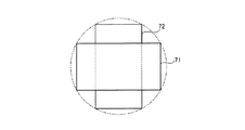
また、第2〜第4の配置例の場合には、視野をカバーし合うように撮像範囲の関連付けを行うことができ、体腔内それぞれの広い視野を確保することができる。図5は、第2の例の場合の撮像素子12a,12bによる撮像領域71,72の位置関係を示す説明図である。撮像素子12a,12bに対応して横長状の撮像領域71,72は、カプセル型内視鏡3の軸心方向に見た場合、撮像素子12a,12bの直交配置関係に対応して直交する配置関係となって体腔内を撮像する。ここで、結像レンズ21a,21bによる撮像領域を例えば図5中に破線円で示すと、横長状の撮像素子12a,12bの場合、上下方向にそれぞれ観察し得ない領域を生じてしまうが、撮像素子12a,12bを直交配置させて撮像領域71,72も直交させることにより、それぞれ単独では観察し得ない領域をカバーし合うように撮像範囲(視野)の関連付けを行うことができ、体腔内の撮像を見落としが少なくなるように行うことができる。
In the case of the second to fourth arrangement examples, the imaging ranges can be associated with each other so as to cover the fields of view, and a wide field of view within the body cavity can be ensured. FIG. 5 is an explanatory diagram showing the positional relationship between the
同様に、図7は、第3の例の撮像素子12a,12bによる撮像領域71,72の位置関係を示す説明図である。撮像素子12a,12bに対応して横長状の撮像領域71,72は、カプセル型内視鏡3の軸心方向に見た場合、撮像素子12a,12bの上下反転配置関係に対応して上下反転した配置関係となって体腔内を撮像する。ここで、結像レンズ21a,21bによる撮像領域を例えば図7中に破線円で示すと、横長状の撮像素子12a,12bの場合、上下方向にそれぞれ観察し得ない領域を生じてしまうが、撮像素子12a,12bをカプセル型内視鏡3の軸心に対して上下方向に偏心配置させ、かつ、上下反転させて撮像領域71,72を設定することにより、撮像領域71としては体腔内の上部側を、撮像領域72としては体腔内の下部側をそれぞれ撮像することとなり、それぞれ単独では観察し得ない領域をカバーし合うように撮像範囲(視野)の関連付けを行うことができ、体腔内の撮像を見落としが少なくなるように行うことができる。
Similarly, FIG. 7 is an explanatory diagram showing the positional relationship between the
また、図9は、撮像素子12a,12bによる撮像領域73,74の位置関係を示す説明図である。撮像素子12a,12bに対応して撮像領域73,74は、カプセル型内視鏡3の軸心方向に見た場合、撮像素子12a,12bの45度回転させた配置関係に対応する配置関係で体腔内を撮像する。ここで、結像レンズ21a,21bによる撮像領域を例えば図20中に破線円で示すと、撮像素子12a,12bの場合、上下左右方向にそれぞれ観察し得ない領域を生じてしまうが、撮像素子12a,12bを45度回転させて撮像領域73,74も45度異なるように配置させることにより、より結像レンズ21a,21bによる撮像領域(円)に近づき、それぞれ単独では観察し得ない領域をカバーし合うように撮像範囲(視野)の関連付けを行うことができ、体腔内の撮像を見落としが少なくなるように行うことができる。
FIG. 9 is an explanatory diagram showing the positional relationship between the
また、複眼型のカプセル型内視鏡3の場合、胴部筐体16cは可視光に対して不透過な有色材質により形成されているものの、複数の撮像ブロック14a,14bを備えるため、例えば一方の撮像素子12aによる撮像時に他方の照明部11bからの照明光が内部隙間等の経路を経て迷光として入り込み、撮像画質を低下させてしまう可能性がある。撮像素子12bと照明部11aとの関係についても同様である。この点、本実施の形態では、撮像ブロック14a,14b間に存在する胴部筐体16cとほぼ同径の電池29が遮光部材として機能するため、撮像素子12a,12bによる撮像時に他方の照明光の影響を受けて撮像画質が低下するのを防止することができる。なお、電池29に代えて、又は、電池29とともに、胴部筐体16cとほぼ同径に形成した基板を遮光部材として用いるようにしてもよい。
In the case of the compound-
次に、図10を参照して表示装置4について説明する。図10は、図1に示す表示装置4の概略構成を示すブロック図である。図10に示すように、表示装置4は、入力部41、表示部42、記憶部43、及び制御部44を備える。
Next, the
入力部41は、キーボードやマウスなどのポインティングデバイスなどによって実現され、表示装置4の動作指示及び表示装置4が行う処理の指示情報を入力し、各指示情報を制御部44に送出する。表示部42は、CRTディスプレイ、液晶ディスプレイ等によって実現され、入力部41の指示情報或いは指示結果などを表示する。表示部42は、記憶部43の対をなすフォルダF1,F2に格納された画像群Pa,Pb中の画像が並列表示される所定の画像表示領域等を有する。
The input unit 41 is realized by a pointing device such as a keyboard or a mouse, and inputs an operation instruction of the
記憶部43は、例えばハードディスク装置などによって実現され、携帯型記録装置5から取得した各種画像などを保持する。例えば、本実施の形態の場合、フォルダF1内には、カプセル型内視鏡3中の撮像素子12aによって撮像された複数枚のフレーム画像からなる画像群Paが格納され、カプセル型内視鏡3毎にこのフォルダF1と対をなすフォルダF2内には、カプセル型内視鏡3中の撮像素子12bによって撮像された複数枚のフレーム画像からなる画像群Pbが格納される。フォルダF1,F2に格納された画像群Pa,Pbには、画像毎に、受信装置2における画像データの受信順に従ってフレーム番号が付与されている。また、フォルダF2は、前述したように、各カプセル型内視鏡3毎に特定される撮像素子12aに対する撮像素子12bの配置関係に基づく画像表示時の画像処理指示情報を格納するヘッダ情報格納領域を有する。
The
制御部44は、入力部41、表示部42、及び記憶部43の各処理又は動作を制御する。制御部44は、画像処理部45、表示制御部46、及び画像選択部47を備える。画像処理部45は、画像に対して選択的に左右反転処理、上下反転処理、90度回転処理、45度回転処理等の画像処理を行う機能を備え、画像群Pa,Pbに含まれる各フレーム画像に対して適宜画像処理を施す。表示制御部46は、表示部42における表示処理を制御する機能を有し、本実施の形態の場合、特に、フォルダF1,F2に格納された画像群Pa,Pbをもとに、表示部42に対して、所定の画像表示領域に画像を並列表示させる。画像選択部47は、入力部41から画像表示の指示情報が入力された場合、フォルダF1,F2に格納された画像群Pa,Pb中からフレームレートに従いフレーム番号順に画像を1枚ずつ画像処理部45や表示制御部46に対して抽出出力し、画像処理や表示に供する。
The
次に、図11を参照して、表示制御部46による画像表示処理手順について説明する。図11において、まず、入力部41から、カプセル型内視鏡3の前方画像及び後方画像なる両画像の並列表示を指示する指示情報を受信したか否かを判断する(ステップS1)。この指示情報があったと判断した場合(ステップS1:Yes)、画像選択部47に対して、フォルダF2中のヘッダ情報格納領域中のヘッダ情報の読出しを指示するとともに(ステップS2)、フォルダF1,F2に格納された画像群Pa,Pb中の画像をフレーム番号順に従い順次選択して読出す処理を指示する(ステップS3)。そして、フォルダF2中のヘッダ情報格納領域中のヘッダ情報の内容を判断する(ステップS4〜S7)。
Next, an image display processing procedure by the
まず、このヘッダ情報において特に指示無しの場合には(ステップS4:Yes)、フォルダF1,F2から読み出された1枚ずつのフレーム画像をそのまま表示部42の画像表示領域に並列表示させる(ステップS12)。左右反転指示情報が格納されていた場合には(ステップS5:Yes)、フォルダF2から読み出されたフレーム画像を画像処理部51で左右反転処理を行わせ(ステップS8)、フォルダF1から読み出されたフレーム画像とフォルダF2から読出され左右反転処理されたフレーム画像とを表示部42の画像表示領域に並列表示させる(ステップS12)。
First, when there is no instruction in the header information (step S4: Yes), the frame images read from the folders F1 and F2 are displayed in parallel in the image display area of the
一方、90度回転指示情報が格納されていた場合には(ステップS6:Yes)、フォルダF2から読み出されたフレーム画像を画像処理部51で90度回転処理を行わせ(ステップS9)、フォルダF1から読み出されたフレーム画像とフォルダF2から読出され90度回転処理されたフレーム画像とを表示部42の画像表示領域に並列表示させる(ステップS12)。
On the other hand, if 90-degree rotation instruction information is stored (step S6: Yes), the
また、上下反転指示情報が格納されていた場合には(ステップS7:Yes)、フォルダF2から読み出されたフレーム画像を画像処理部51で上下反転処理を行わせ(ステップS10)、フォルダF1から読み出されたフレーム画像とフォルダF2から読出され上下反転処理されたフレーム画像とを表示部42の画像表示領域に並列表示させる(ステップS12)。
If the upside down instruction information is stored (step S7: Yes), the
さらに、45度回転指示情報が格納されていた場合には(ステップS7:No)、フォルダF2から読み出されたフレーム画像を画像処理部51で45度回転処理を行わせ(ステップS11)、フォルダF1から読み出されたフレーム画像とフォルダF2から読出され45度回転処理されたフレーム画像とを表示部42の画像表示領域に並列表示させる(ステップS12)。 Further, if 45 degree rotation instruction information is stored (step S7: No), the frame image read from the folder F2 is rotated 45 degrees by the image processing unit 51 (step S11), and the folder The frame image read from F1 and the frame image read from the folder F2 and rotated by 45 degrees are displayed in parallel in the image display area of the display unit 42 (step S12).
その後、画像の表示終了を指示する指示情報を受信したか否かを判断し(ステップS13)、この指示情報を受信したと判断した場合には(ステップS13:Yes)、表示部42における画像表示を終了させる。一方、画像の表示終了を指示する指示情報を受信していないと判断した場合には(ステップS13:No)、表示部42が最終フレーム画像まで表示したか否かを判断する(ステップS14)。表示部42が最終フレーム画像まで表示したと判断した場合には(ステップS14:Yes)、表示部42における画像表示を終了させる。表示部42が最終フレーム画像まで表示していないと判断した場合には(ステップS14:No)、ステップS3以降の処理を繰り返す。
Thereafter, it is determined whether or not the instruction information for instructing to end the display of the image has been received (step S13). When it is determined that the instruction information has been received (step S13: Yes), the image display on the
次に、図12〜図15を参照して、表示部42の表示画面上において並列表示される画像例について説明する。まず、図12は、ステップS4,S12による場合の表示部42の表示画面の一例を示す図であり、表示部42の表示画面は、撮像素子12a,12bにより撮像された検査画像を表示する主観察モニタ51部分を有する。本実施の形態では、この主観察モニタ51部分を利用して撮像素子12a,12bによる撮像画像が並列表示される。
Next, an example of an image displayed in parallel on the display screen of the
図12において、52は、検査日一覧を表示するファイリングリスト欄であり、検査日毎に患者名が一覧表示される。検査日下の患者名を選択すると主観察モニタ51部分に該患者の検査の先頭画像が表示される。53は、主観察モニタ51部分の再生方法を変更するための再生コントローラ部分であり、再生、一時停止、コマ送り、先頭出し、終端出し等の各ボタンを選択自在に有する。再生コントローラ53部分で再生ボタンを選択すると、主観察モニタ51部分に静止画像を連続的に表示することで、擬似的な動画表示を行う。54は、再生速度を低速/高速の2段階で切換えるための再生速度変更ボタンである。55は、観察モニタ51部分に表示する枚数を1枚/2枚/4枚で切換えるための表示枚数変更ボタンであり、例えばこの表示枚数変更ボタン55により2枚表示を選択指示することにより、観察モニタ51部分には撮像素子12a,12bにより撮像された検査画像が左右に並列表示される。56は、バー全体の長さが例えば10時間とされた画像処理標識バー部分であり、再生中の画像の時間的な位置を表示する。
In FIG. 12, 52 is a filing list field for displaying a list of examination dates, and a list of patient names is displayed for each examination date. When the patient name under the examination date is selected, the head image of the examination of the patient is displayed on the main observation monitor 51 portion.
57は、観察モニタ51部分に表示中の画像をダブルクリックすることでピックアップされた画像を示し、選択画像リスト欄58に縮小表示される。同時に、画像処理標識バー56の選択画像が対応する位置と選択画像の上部とが線で結ばれ、時間的な位置関係が明示される。
図12は、図11中のステップS4,S12の表示制御処理に従い、撮像素子12a,12bによりほぼ同一タイミングで撮像された前画像61と後画像62とが主観察モニタ51部分において横並びで並列表示されている表示例を示している。すなわち、前画像61は撮像素子12aにより体腔内において前方方向を撮像した画像例であり、後画像62は撮像素子12bにより体腔内において後方方向を撮像した画像例である。ここで、第1の配置例の場合には、撮像素子12a,12bによる撮像画像を回転等の処理を施さずにそのまま表示させているため、前向きの画像と後ろ向きの画像とがそのまま並列表示されることとなるが、撮像素子12a,12bの配置関係は、上下方向が一致し左右方向のみが逆となっていることが判っているので、図12に示す表示画面を見る医者や看護士は、2つの画像61,62の対応位置関係が左右対称的であることを知ることができる。例えば、前画像61において左寄りに出現した異常部位と後画像62において右寄りに出現した異常部位とは同一部位であると簡単かつ正確に判断することができる。
In FIG. 12, the
図13は、第1の配置例において、ユーザ等の要求に応じて、左右反転処理を指示する情報がヘッダ情報として付加される場合(ステップS5,S12)の表示部42の表示画面の一例を示す図であり、主観察モニタ51部分を利用して撮像素子12a,12bによる撮像画像が並列表示される。図12との対比では、撮像素子12bにより体腔内において後方方向を撮像した後画像62が、左右反転させて表示されている。すなわち、撮像素子12a,12bの配置関係は、上下方向が一致し左右方向のみが逆となっているのに対して、一方の撮像素子12bによる画像を左右反転させて表示させているので、車の運転者がフロントガラスから前方を見ながら(前画像61を見ながら)、バックミラーで後方を見る(後画像62を見る)感覚で、両画像61,62を観察することができ、表示画像の左右方向が一致するので、両画像61,62の対応位置関係が判りやすく、診断の高速化を図ることができる。例えば、前画像61において左寄りに出現した異常部位と後画像62において左寄りに出現した異常部位とは同一部位であると簡単かつ正確に判断することができる。
FIG. 13 shows an example of the display screen of the
図14は、第2の配置例において90度回転指示を伴うステップS6,S12の場合の表示部42の表示画面の一例を示す図であり、主観察モニタ51部分を利用して撮像素子12a,12bによる撮像画像63,64が並列表示される。ここで、一方の撮像素子12aによる前画像63がそのまま表示されるのに対して、他方の撮像素子12bによる後画像64は90度回転させることにより縦長画像として表示される。つまり、撮像素子12bは上下方向が90度回転させて配設されているが、その撮像画像の表示に際しては撮像素子12bの上下方向が表示の天地方向に一致するように修正せず、90度回転処理により撮像素子12aの撮像時の上下方向に一致する状態で表示させるものである。これにより、撮像素子12a,12bの撮像時の上下方向が一致する状態で両画像63,64が並列表示されるため、両画像63,64の対応位置関係が判りやすいものとなる。
FIG. 14 is a diagram showing an example of the display screen of the
図15は、第3の配置例において上下反転指示を伴うステップS7,S12の場合の表示部42の表示画面の一例を示す図であり、主観察モニタ51部分を利用して撮像素子12a,12bによる撮像画像63,64が上下に並列表示される。ここで、一方の撮像素子12aによる前画像63がそのまま表示されるのに対して、他方の撮像素子12bによる後画像64は上下反転させた画像として表示される。つまり、撮像素子12bは上下方向が180度回転させて配設されているが、その撮像画像の表示に際しては撮像素子12bの上下方向が表示の天地方向に一致するように修正せず、上下反転処理により撮像素子12aの撮像時の上下方向に一致する状態で表示させるものである。これにより、撮像素子12a,12bの撮像時の上下方向が一致する状態で両画像63,64が上下に並列表示されるため、両画像63,64の対応位置関係が判りやすいものとなる。
FIG. 15 is a diagram illustrating an example of the display screen of the
ところで、図16を参照して、本実施の形態のカプセル型内視鏡3の作製方法について説明する。図16は、本実施の形態のカプセル型内視鏡3の作製方法を示す分解断面図である。まず、一方の先端カバー筐体16bと胴部筐体16cとを接着剤により接合させることにより、有底筐体16´を形成する(工程[1])。次いで、胴部筐体16cの開口部16d側から撮像ブロック14bを落とし込みにより有底筐体16´内に装填する(工程[2])。この落とし込み操作により、撮像ブロック14bの照明基板25bを位置決め部31bに突き当て当接させることにより撮像ブロック14bの軸方向の位置決めがされる。同時に、撮像ブロック14bを有底筐体16´内で少し回動させることで回転止め位置決め部同士を係合させることにより、軸心周り方向の位置決めもなされる。これにより、組立て精度のよい撮像ブロック14bの装填が可能となる。
By the way, with reference to FIG. 16, the manufacturing method of the
撮像ブロック14bの装填に引き続き、今度は、電池29を有底筐体16´内に落とし込みにより装填し(工程[3])、さらに、他方の撮像ブロック14aも有底筐体16´内に落とし込みにより装填し(工程[4])、最後に、胴部筐体16cの開口部16dに対して先端カバー筐体16aを接合させる(工程[5])ことにより、カプセル型内視鏡3が完成する。なお、撮像ブロック14aを先端カバー筐体16a内に装填した状態でこの先端カバー筐体16aを胴部筐体16cの開口部16dに対して接合させるようにしてもよい。
Following the loading of the
このような操作において、撮像ブロック14aの照明基板25aを位置決め部31aに突き当て当接させることにより撮像ブロック14aの軸方向の位置決めがされる。同時に、撮像ブロック14aを有底筐体16´内で適宜回動させておくことで回転止め位置決め部同士を係合させることにより、軸心周り方向の位置決めもなされる。これにより、組立て精度のよい撮像ブロック14aの装填が可能となる。
In such an operation, the
なお、胴部筐体16cと先端カバー筐体16a,16bとの間に、回転止め位置決め部の位置を合わせるマーク等の目印を付しておき、第1の配置例の場合であれば、先端カバー筐体16a,16bの回転止め位置決め部の位置を一致させることにより、カプセル型筐体16内に装填された撮像ブロック14a,14bの撮像素子12a,12bの上下方向が一致するように揃えることができる。
In addition, in the case of the first arrangement example, a mark such as a mark for aligning the position of the rotation stopper positioning portion is attached between the
第2の配置例の場合であれば、先端カバー筐体16a,16bの回転止め位置決め部の位置を90度異ならせることにより、カプセル型筐体16内に装填された撮像ブロック14a,14bの撮像素子12c,12dの上下方向が両者間で90度異なるように配設させることができる。第3の配置例の場合であれば、先端カバー筐体16a,16bの回転止め位置決め部の位置を180度異ならせることにより、カプセル型筐体16内に装填された撮像ブロック14a,14bの撮像素子12c,12dの上下方向が両者間で180度異なるように配設させることができる。第4の配置例の場合であれば、先端カバー筐体16a,16bの回転止め位置決め部の位置を45度異ならせることにより、カプセル型筐体16内に装填された撮像ブロック14a,14bの撮像素子12a,12bの上下方向が両者間で45度異なるように配設させることができる。
In the case of the second arrangement example, the imaging blocks 14a and 14b loaded in the
このように、本実施の形態のカプセル型内視鏡3の作製方法によれば、複眼型であっても、あらかじめ一方の先端カバー筐体16bと胴部筐体16cとを接合させて有底筐体16´を形成しておくことにより、撮像ブロック14b,14a等の内蔵物を一方向からの落とし込み操作により装填することができ、組立性が向上する。また、位置決め部31aにより撮像ブロック14a,14bの軸方向及び軸心周り方向の位置決めがなされる上に、電池29と撮像ブロック14a,14bとの間にはばね部材30a,30bが介在されてそれぞれの撮像ブロック14a,14bが先端カバー筐体16a,16b側に付勢される装填状態となるため、組立て精度がよく、かつ、その精度を維持することもできる。
As described above, according to the method for manufacturing the
(変形例1)
図17を参照して変形例1について説明する。図17は、変形例1のカプセル型内視鏡3の構成例を示す断面図である。本実施の形態では、一方の先端カバー筐体16bと胴部筐体16cとを接着剤により接合させて有底筐体16´を形成するようにしたが、変形例1は、先端カバー筐体16b´と胴部筐体16c´とを有底筐体16´´としてあらかじめ一体成型により形成しておくようにしたものである。これにより、図16を参照して説明した一方向からの落とし込みによる組立てが可能となる。
(Modification 1)
ここで、有底筐体16´´において先端カバー筐体16b´部分には可視光の透過性が要求され、胴部筐体16c´には可視光の不透過性が要求される。そこで、変形例1では、有底筐体16´´を一体成型する上で、胴部筐体16c´部分は可視光を不透過な有色材質とする2色成型法により形成される。有底筐体16´´全体を透明材質により一体成型し、胴部筐体16c´部分の内部又は外部に塗装により着色を施すことも可能である。
Here, in the bottomed
(変形例2)
図18を参照して変形例2について説明する。図18は、変形例2のカプセル型内視鏡3の内部構成例を示す断面図である。変形例2のカプセル型内視鏡3は、撮像ブロック14a,14bの光軸方向(撮像方向)がカプセル型内視鏡3自身の軸心に対して、平行ではなく、斜め方向となるように設定されてカプセル型筐体16内に配設されている。このような斜め配置を行わせるため、先端カバー筐体16a,16bの位置決め部31a,31bもカプセル型内視鏡3の軸心に対して直交状態ではなく斜め状態となるように形成されている。ここで、胴部筐体16cに対する先端カバー筐体16a,16bの接合取り付け状態では、位置決め部31a,31b同士が平行となるように設定されている。また、撮像ブロック14a,14bを斜めの位置決め部31a,31b側に付勢するようにばね部材30a,30bも、くの字形ばねが用いられている。
(Modification 2)
また、撮像ブロック14a,14b中に含まれる撮像素子12a,12bは、両者の上下方向が所定角度ずれるように、相互間の配置関係が関連付けられてカプセル型筐体16内に配設されている。具体的には、撮像素子12a,12bは、上下方向を両者間で180度異ならせて、つまり、上下反転させて配設されている。したがって、これらの撮像素子12a,12bが撮像した画像は、前述した場合と同様に、例えば撮像素子12b側の画像を上下反転させて並列表示させるようにすればよい。
Further, the
変形例2によれば、それぞれの撮像素子12a,12bの撮像方向がカプセル型内視鏡3の軸心に対して斜め方向に設定されているので、例えば、体腔内の撮像に関して、上側を撮像素子12aによる前画像として撮像し、下側を撮像素子12bによる後画像として撮像することができ、体腔内の観察を見落としが少なくなるように行うことができる。
According to the second modification, the imaging directions of the
本発明は、上述した実施の形態に限らず、本発明の趣旨を逸脱しない範囲であれば、種々の変形が可能である。 The present invention is not limited to the above-described embodiment, and various modifications can be made without departing from the spirit of the present invention.
(付記1) カプセル型筐体と、
前記カプセル型筐体内に配設されて体腔内部を照明する複数の照明手段と、
相互間の配置方向が関連付けられて前記カプセル型筐体内に配設されて対をなす前記照明手段とによりそれぞれ撮像ブロックを構成して体腔内における前記カプセル型筐体の進行方向前後の画像を撮像する複数の撮像手段と、
を備えたことを特徴とする被検体内導入装置。
(Supplementary note 1) Capsule type housing,
A plurality of illuminating means disposed in the capsule-type housing for illuminating the inside of the body cavity;
An imaging block is formed by the illumination means arranged in the capsule casing and associated with each other in the direction of arrangement, and images before and after the capsule casing in the body cavity are taken. A plurality of imaging means,
An intra-subject introduction apparatus characterized by comprising:
(付記2) 前記各撮像ブロックのそれぞれの前記撮像素子は、両者の上下方向を一致させて前記カプセル型筐体内に配設されていることを特徴とする付記1に記載の被検体内導入装置。
(Additional remark 2) Each said image pick-up element of each said image pick-up block is arrange | positioned in the said capsule-type housing | casing, making the up-down direction of both correspond, The in-subject introduction apparatus of
(付記3) 前記各撮像ブロックのそれぞれの前記撮像素子は、両者の上下方向を相対的に所定角度ずらして前記カプセル型筐体内に配設されていることを特徴とする付記1に記載の被検体内導入装置。 (Additional remark 3) Each said image pick-up element of each said image pick-up block is arrange | positioned in the said capsule-type housing | casing by mutually shifting the up-down direction of both by a predetermined angle relatively, Intrasample introduction device.
(付記4) 前記各撮像ブロックのそれぞれの前記撮像素子は、上下方向を両者間で180度異ならせて前記カプセル型筐体内に配設されていることを特徴とする付記3に記載の被検体内導入装置。
(Supplementary note 4) The subject according to
(付記5) 前記各撮像ブロックのそれぞれの前記撮像素子は、当該被検体内導入装置の軸心に対して上下方向に偏心配置されていることを特徴とする付記4に記載の被検体内導入装置。
(Additional remark 5) Each said image pick-up element of each said imaging block is eccentrically arranged to the up-down direction with respect to the axial center of the said intra-subject introduction apparatus, The in-subject introduction of
(付記6) 前記各撮像ブロックのそれぞれの前記撮像素子は、所定のアスペクト比を持つ横長状の素子であることを特徴とする付記5に記載の被検体内導入装置。
(Supplementary note 6) The in-subject introduction apparatus according to
(付記7) 前記各撮像ブロックのそれぞれの前記撮像素子は、撮像方向が当該被検体内導入装置の軸心に対して斜め方向に設定されていることを特徴とする付記4に記載の被検体内導入装置。
(Supplementary note 7) The subject according to
(付記8) 前記各撮像ブロックのそれぞれの前記撮像素子は、所定のアスペクト比を持つ横長状の素子であって、上下方向を両者間で90度異ならせて前記カプセル型筐体内に配設されていることを特徴とする付記3に記載の被検体内導入装置。
(Additional remark 8) Each said image pick-up element of each said image pick-up block is a horizontally long element which has a predetermined aspect ratio, Comprising: A vertical direction differs 90 degree | times between both, and it is arrange | positioned in the said capsule-type housing | casing. The in-subject introduction device according to
(付記9) 前記各撮像ブロックのそれぞれの前記撮像素子は、略正方形状の素子であって、上下方向を両者間で45度異ならせて前記カプセル型筐体内に配設されていることを特徴とする付記3に記載の被検体内導入装置。
(Additional remark 9) Each said image pick-up element of each said image pick-up block is a substantially square-shaped element, Comprising: The up-down direction differs 45 degree | times between both, It is arrange | positioned in the said capsule-type housing | casing. The in-subject introduction device according to
(付記10) 前記カプセル型筐体は、前記各撮像ブロックが配設される円筒状の胴部筐体と、該胴部筐体と水密に設けられ、該撮像ブロックをそれぞれ覆うと共に前記照明手段からの照明光を導出する透明な先端カバー筐体とよりなり、
前記各撮像ブロックをそれぞれ相対向する前記先端カバー筐体側に付勢する弾性部材をさらに備えたことを特徴とする付記1〜9のいずれか一つに記載の被検体内導入装置。
(Supplementary Note 10) The capsule-type casing is provided with a cylindrical trunk casing in which the respective imaging blocks are disposed, and is provided in a watertight manner with the trunk casing. It consists of a transparent tip cover housing that guides the illumination light from
10. The intra-subject introduction apparatus according to any one of
(付記11) 前記弾性部材は、ばね部材よりなることを特徴とする付記10に記載の被検体内導入装置。
(Supplementary note 11) The in-subject introduction apparatus according to
(付記12) 前記撮像ブロック間に介在された遮光部材をさらに備えたことを特徴とする付記1〜11のいずれか一つに記載の被検体内導入装置。
(Supplementary note 12) The intra-subject introduction apparatus according to any one of
(付記13) 前記遮光部材は、前記撮像素子や前記照明手段に電力を供給する電池であることを特徴とする付記12に記載の被検体内導入装置。 (Additional remark 13) The said light-shielding member is a battery which supplies electric power to the said image pick-up element and the said illumination means, The in-subject introduction apparatus of Additional remark 12 characterized by the above-mentioned.
(付記14) 前記遮光部材は、前記撮像素子や前記照明手段を実装した基板であることを特徴とする付記12に記載の被検体内導入装置。 (Additional remark 14) The said light shielding member is a board | substrate which mounted the said image pick-up element and the said illumination means, The in-subject introduction apparatus of Additional remark 12 characterized by the above-mentioned.
(付記15) 前記カプセル型筐体は、前記各撮像ブロックが配設される円筒状の胴部筐体と、該胴部筐体と水密に設けられ、該撮像ブロックをそれぞれ覆うと共に前記照明手段からの照明光を導出する透明な先端カバー筐体とよりなり、該胴部筐体と一方の前記先端カバー筐体とが有底筐体として一体に成型されていることを特徴とする付記1〜14のいずれか一つに記載の被検体内導入装置。 (Supplementary Note 15) The capsule casing is provided with a cylindrical trunk casing in which the respective imaging blocks are disposed, and is provided in a watertight manner with the trunk casing. And a transparent front cover housing for guiding illumination light from the body, and the body housing and one of the front cover housings are integrally molded as a bottomed housing. The intra-subject introduction device according to any one of -14.
(付記16) 前記有底筐体の前記胴部筐体部分は、可視光を不透過な有色材質よりなることを特徴とする付記15に記載の被検体内導入装置。
(Supplementary note 16) The in-subject introduction apparatus according to
(付記17) 付記1〜9のいずれか一つに記載の被検体内導入装置と、
該被検体内導入装置のそれぞれの撮像素子によって時系列で撮像された体腔内の画像を取得する取得手段と、
それぞれの前記撮像素子によって撮像されて取得された画像同士を、該撮像素子の相互間の配置方向の関連付けに対応するように関連付けて表示部に表示させる表示制御手段と、
を備えたことを特徴とする被検体内情報取得システム。
(Supplementary Note 17) The intra-subject introduction apparatus according to any one of
Obtaining means for obtaining an image of a body cavity imaged in time series by each imaging device of the intra-subject introduction device;
Display control means for displaying on the display unit the images acquired by being captured by the respective image sensors in association with each other so as to correspond to the association of the arrangement directions of the image sensors;
An in-subject information acquisition system comprising:
(付記18) 前記表示制御手段は、上下方向を一致させた前記撮像素子によって撮像された両方の画像をそのまま表示するように制御することを特徴とする付記17に記載の被検体内情報取得システム。 (Supplementary note 18) The in-vivo information acquiring system according to supplementary note 17, wherein the display control means performs control so that both images picked up by the imaging elements whose vertical directions coincide with each other are displayed as they are. .
(付記19) 前記表示制御手段は、上下方向を一致させた前記撮像素子によって撮像された画像のうち、一方の画像を左右反転させて表示するように制御することを特徴とする付記17に記載の被検体内情報取得システム。 (Supplementary note 19) The supplementary note 17 is characterized in that the display control means performs control so that one of the images picked up by the image pickup devices whose vertical directions coincide with each other is displayed while being horizontally reversed. In-subject information acquisition system.
(付記20) 前記表示制御手段は、上下方向を相対的に180度異ならせた前記撮像素子によって撮像された画像のうち、一方の画像を上下反転させて表示するように制御することを特徴とする付記17に記載の被検体内情報取得システム。 (Additional remark 20) The said display control means is controlled to display one image upside down among the images imaged with the said image pick-up element which made the up-down direction different 180 degree | times, and to display it. The in-subject information acquisition system according to appendix 17.
(付記21) 前記表示制御手段は、上下方向を相対的に90度異ならせた前記撮像素子によって撮像された画像のうち、一方の画像を90度回転させて表示するように制御することを特徴とする付記17に記載の被検体内情報取得システム。 (Additional remark 21) The said display control means is controlled to rotate and display one image 90 degree | times among the images imaged by the said image pick-up element which made the up-down direction different 90 degree | times relatively. The in-subject information acquisition system according to appendix 17.
(付記22) 前記表示制御手段は、上下方向を相対的に45度異ならせた前記撮像素子によって撮像された画像のうち、一方の画像を45度回転させて表示するように制御することを特徴とする付記17に記載の被検体内情報取得システム。 (Additional remark 22) The said display control means is controlled to rotate and display one image among the images imaged by the said image pick-up element which made the up-down direction different 45 degree | times relatively. The in-subject information acquisition system according to appendix 17.
(付記23) 体腔内部を照明する照明手段と体腔内の画像を撮像する撮像素子とをそれぞれ有する複数の撮像ブロックを、円筒状の胴部筐体と該胴部筐体と水密に設けられ前記各撮像ブロックをそれぞれ覆うと共に前記照明手段からの照明光を導出する透明な先端カバー筐体とよりなるカプセル型筐体内に配設し、体腔内における該カプセル型筐体の進行方向前後の画像を撮像する複眼型の被検体内導入装置の作製方法であって、
一方の前記先端カバー筐体と前記胴部筐体とを接合して有底筐体を形成する工程と、
形成された前記有底筐体に対して前記胴体筐体の開口部から一方の撮像ブロックを落とし込みにより軸方向及び軸心周り方向の位置決めを行って装填する工程と、
を含むことを特徴とする被検体内導入装置の作製方法。
(Supplementary Note 23) A plurality of imaging blocks each having an illuminating means for illuminating the inside of a body cavity and an imaging element for imaging an image in the body cavity are provided in a cylindrical body housing and the body housing in a watertight manner. Each of the imaging blocks is disposed in a capsule-type casing that includes a transparent tip cover casing that guides illumination light from the illuminating means, and images of the capsule-type casing in the body cavity before and after the traveling direction are displayed. A method for producing a compound eye type in-subject introduction device for imaging,
Joining the one end cover housing and the body housing to form a bottomed housing;
A step of loading one imaging block from the opening of the body casing with respect to the formed bottomed casing by positioning in the axial direction and the direction around the axial center, and loading,
A method for producing an in-subject introduction device, comprising:
3 カプセル型内視鏡
11a,11b 照明部
12a,12b 撮像素子
14a,14b 撮像ブロック
16 カプセル型筐体
16a,16b 先端カバー筐体
16c 胴部筐体
16´ 有底筐体
29 電池
30 ばね部材
41 入力部
42 表示部
46 表示制御部
3
Claims (17)
前記カプセル型筐体内に配設されて体腔内部を照明する複数の照明手段と、
相互間の配置方向が関連付けられて前記カプセル型筐体内に配設されて対をなす前記照明手段とによりそれぞれ撮像ブロックを構成して体腔内における前記カプセル型筐体の進行方向前後の画像を撮像する複数の撮像手段と、
を備えると共に、
前記撮像手段で撮像された画像に対して撮像素子相互間の配置関係に基く画像表示時の画像処理指示情報を併せて記録することを特徴とする被検体内導入装置。 A capsule housing;
A plurality of illuminating means disposed in the capsule-type housing for illuminating the inside of the body cavity;
An imaging block is formed by the illumination means arranged in the capsule casing and associated with each other in the direction of arrangement, and images before and after the capsule casing in the body cavity are taken. A plurality of imaging means,
The equipped Rutotomoni,
An in-subject introduction apparatus , wherein image processing instruction information at the time of image display based on an arrangement relationship between imaging elements is recorded together with an image captured by the imaging means .
該被検体内導入装置のそれぞれの撮像素子によって時系列で撮像された体腔内の画像を取得する取得手段と、
それぞれの前記撮像素子によって撮像されて取得された画像同士を、該撮像素子の相互間の配置方向の関連付けに対応するように関連付けて表示部に表示させる表示制御手段と、
を備えたことを特徴とする被検体内情報取得システム。 Intra-subject introduction device according to any one of claims 1 to 9,
Obtaining means for obtaining an image of a body cavity imaged in time series by each imaging device of the intra-subject introduction device;
Display control means for displaying on the display unit the images acquired by being captured by the respective image sensors in association with each other so as to correspond to the association of the arrangement directions of the image sensors;
An in-subject information acquisition system comprising:
少なくとも一つの撮像素子によって取得された画像を上下反転または左右反転させて表示する表示制御手段と、
を備えたことを特徴とする請求項1に記載の被検体内情報表示装置。 An acquisition means for acquiring images of a body cavity imaged in time series by a plurality of imaging elements of the intra-subject introduction device;
Display control means for displaying an image acquired by at least one image sensor by vertically or horizontally inverting the image;
The in-subject information display device according to claim 1, further comprising:
該被検体内導入装置のそれぞれの撮像素子によって時系列で撮像された体腔内の画像を取得する取得手段と、
少なくとも一つの撮像素子によって取得された画像を上下反転または左右反転させて表示する表示制御手段と、
を備えたことを特徴とする被検体内情報取得システム。 Intra-subject introduction device according to any one of claims 1 to 9,
Obtaining means for obtaining an image of a body cavity imaged in time series by each imaging device of the intra-subject introduction device;
Display control means for displaying an image acquired by at least one image sensor by vertically or horizontally inverting the image;
An in-subject information acquisition system comprising:
Priority Applications (7)
| Application Number | Priority Date | Filing Date | Title |
|---|---|---|---|
| JP2005115027A JP4695432B2 (en) | 2005-04-12 | 2005-04-12 | In-subject introduction apparatus, in-subject information display apparatus, and in-subject information acquisition system |
| PCT/JP2006/302873 WO2006109370A1 (en) | 2005-04-12 | 2006-02-17 | Device to be introduced into subject, system for acquiring information on inside of subject, and method of producing device to be introduced into subject |
| EP06714014.5A EP1870019B1 (en) | 2005-04-12 | 2006-02-17 | Device to be introduced into subject, system for acquiring information on inside of subject, and method of producing device to be introduced into subject |
| US11/572,784 US8038607B2 (en) | 2005-04-12 | 2006-02-17 | Body insertable apparatus with a plurality of imaging blocks |
| AU2006233956A AU2006233956B2 (en) | 2005-04-12 | 2006-02-17 | Device to be introduced into subject, system for acquiring information on inside of subject, and method of producing device to be introduced into subject |
| CN2006800119565A CN101160087B (en) | 2005-04-12 | 2006-02-17 | Body-insertable apparatus, in-vivo and information acquiring system |
| US11/699,127 US7959562B2 (en) | 2005-04-12 | 2007-01-29 | Body-insertable apparatus, in-vivo information acquiring system, and body-insertable apparatus manufacturing method |
Applications Claiming Priority (1)
| Application Number | Priority Date | Filing Date | Title |
|---|---|---|---|
| JP2005115027A JP4695432B2 (en) | 2005-04-12 | 2005-04-12 | In-subject introduction apparatus, in-subject information display apparatus, and in-subject information acquisition system |
Related Child Applications (1)
| Application Number | Title | Priority Date | Filing Date |
|---|---|---|---|
| JP2007228757A Division JP4914790B2 (en) | 2007-09-04 | 2007-09-04 | Intra-subject introduction device and method for producing intra-subject introduction device |
Publications (3)
| Publication Number | Publication Date |
|---|---|
| JP2006288832A JP2006288832A (en) | 2006-10-26 |
| JP2006288832A5 JP2006288832A5 (en) | 2007-09-27 |
| JP4695432B2 true JP4695432B2 (en) | 2011-06-08 |
Family
ID=37086664
Family Applications (1)
| Application Number | Title | Priority Date | Filing Date |
|---|---|---|---|
| JP2005115027A Expired - Fee Related JP4695432B2 (en) | 2005-04-12 | 2005-04-12 | In-subject introduction apparatus, in-subject information display apparatus, and in-subject information acquisition system |
Country Status (6)
| Country | Link |
|---|---|
| US (2) | US8038607B2 (en) |
| EP (1) | EP1870019B1 (en) |
| JP (1) | JP4695432B2 (en) |
| CN (1) | CN101160087B (en) |
| AU (1) | AU2006233956B2 (en) |
| WO (1) | WO2006109370A1 (en) |
Families Citing this family (25)
| Publication number | Priority date | Publication date | Assignee | Title |
|---|---|---|---|---|
| US7662094B2 (en) | 2002-05-14 | 2010-02-16 | Given Imaging Ltd. | Optical head assembly with dome, and device for use thereof |
| US20070167834A1 (en) * | 2005-12-29 | 2007-07-19 | Amit Pascal | In-vivo imaging optical device and method |
| US9320417B2 (en) * | 2005-12-29 | 2016-04-26 | Given Imaging Ltd. | In-vivo optical imaging device with backscatter blocking |
| JP5025720B2 (en) | 2007-02-22 | 2012-09-12 | オリンパスメディカルシステムズ株式会社 | Intra-subject introduction system |
| JP5074146B2 (en) * | 2007-03-30 | 2012-11-14 | オリンパス株式会社 | Capsule medical device |
| JP5000357B2 (en) * | 2007-03-30 | 2012-08-15 | オリンパスメディカルシステムズ株式会社 | Capsule type medical device manufacturing method and capsule type medical device |
| JP5340557B2 (en) | 2007-05-08 | 2013-11-13 | オリンパスメディカルシステムズ株式会社 | Capsule medical device |
| JP4914790B2 (en) * | 2007-09-04 | 2012-04-11 | オリンパスメディカルシステムズ株式会社 | Intra-subject introduction device and method for producing intra-subject introduction device |
| JP2009225875A (en) * | 2008-03-19 | 2009-10-08 | Olympus Corp | Endoscope system |
| US8235888B2 (en) * | 2008-07-08 | 2012-08-07 | Olympus Medical Systems Corp. | System for guiding capsule medical device |
| US8262566B2 (en) * | 2008-07-14 | 2012-09-11 | Given Imaging Ltd. | Device and method for uniform in vivo illumination |
| JP5317639B2 (en) * | 2008-11-17 | 2013-10-16 | Hoya株式会社 | Endoscope |
| CN102361585B (en) | 2009-03-23 | 2014-06-25 | 奥林巴斯医疗株式会社 | Image processing system, external apparatus and image processing method therefor |
| JP2011082215A (en) * | 2009-10-02 | 2011-04-21 | Olympus Corp | Image sensor, and imaging unit |
| WO2011061968A1 (en) * | 2009-11-19 | 2011-05-26 | オリンパスメディカルシステムズ株式会社 | Medical device system, capsule medical device system, and method for displaying posture items of body to be tested |
| TWI422349B (en) * | 2010-05-03 | 2014-01-11 | Univ Ishou | Capsule endoscopy |
| EP2684511A4 (en) * | 2011-07-22 | 2014-12-17 | Olympus Medical Systems Corp | Capsule-type endoscope system, image display method, and image display program |
| US9345393B2 (en) * | 2012-03-13 | 2016-05-24 | Panasonic Intellectual Property Management Co., Ltd. | Endoscope camera |
| US9170590B2 (en) | 2012-10-31 | 2015-10-27 | Qualcomm Incorporated | Method and apparatus for load adaptive LDO bias and compensation |
| US9235225B2 (en) | 2012-11-06 | 2016-01-12 | Qualcomm Incorporated | Method and apparatus reduced switch-on rate low dropout regulator (LDO) bias and compensation |
| US8981745B2 (en) | 2012-11-18 | 2015-03-17 | Qualcomm Incorporated | Method and apparatus for bypass mode low dropout (LDO) regulator |
| US9876992B2 (en) | 2014-04-30 | 2018-01-23 | Panasonic Intellectual Property Management Co., Ltd. | Imaging apparatus and distance measuring apparatus using the same |
| CN106455917B (en) | 2014-08-08 | 2018-06-19 | 奥林巴斯株式会社 | Encapsulated medical device guiding system |
| CN107049212A (en) * | 2017-03-22 | 2017-08-18 | 重庆金山医疗器械有限公司 | Camera lens tilting capsule endoscope |
| CN111432773B (en) * | 2017-12-18 | 2021-12-28 | 卡普索影像公司 | Device for stomach examination by capsule camera |
Citations (2)
| Publication number | Priority date | Publication date | Assignee | Title |
|---|---|---|---|---|
| JP2003070728A (en) * | 2001-06-20 | 2003-03-11 | Olympus Optical Co Ltd | Capsule type endoscope |
| JP2005503182A (en) * | 2001-01-16 | 2005-02-03 | ギブン・イメージング・リミテツド | System and method for wide area imaging of body cavities |
Family Cites Families (21)
| Publication number | Priority date | Publication date | Assignee | Title |
|---|---|---|---|---|
| JPS57156736A (en) * | 1981-03-23 | 1982-09-28 | Olympus Optical Co | Therapeutic capsule apparatus |
| US7553276B2 (en) * | 2001-01-16 | 2009-06-30 | Given Imaging Ltd. | Method and device for imaging body lumens |
| KR100413058B1 (en) * | 2001-04-24 | 2003-12-31 | 한국과학기술연구원 | Micro Robotic Colonoscope with Motor Locomotion |
| IL143260A (en) | 2001-05-20 | 2006-09-05 | Given Imaging Ltd | Array system and method for locating an in vivo signal source |
| ATE404114T1 (en) * | 2001-06-18 | 2008-08-15 | Given Imaging Ltd | SWALLOWABLE IN-VIVO CAPSULE WITH A CIRCUIT BOARD HAVING RIGID AND FLEXIBLE SECTIONS |
| US6939292B2 (en) * | 2001-06-20 | 2005-09-06 | Olympus Corporation | Capsule type endoscope |
| US6951536B2 (en) * | 2001-07-30 | 2005-10-04 | Olympus Corporation | Capsule-type medical device and medical system |
| ATE372028T1 (en) * | 2002-02-12 | 2007-09-15 | Given Imaging Ltd | SYSTEM AND METHOD FOR DISPLAYING AN IMAGE STREAM |
| JP2004129949A (en) * | 2002-10-11 | 2004-04-30 | Olympus Corp | Capsule endoscope |
| JP2006512130A (en) * | 2002-12-26 | 2006-04-13 | ギブン・イメージング・リミテツド | Immobilizable in vivo sensing device |
| DE10323216B3 (en) * | 2003-05-22 | 2004-12-23 | Siemens Ag | Endoscope apparatus has cameras which are provided at respective ends of endoscope capsule, such that one of camera is tilted or rotated to change photography range |
| US20050043582A1 (en) * | 2003-06-17 | 2005-02-24 | Stokes Michael J. | Surgical instrument having an increased range of motion |
| JP2005074031A (en) * | 2003-09-01 | 2005-03-24 | Pentax Corp | Capsule endoscope |
| US7647090B1 (en) * | 2003-12-30 | 2010-01-12 | Given Imaging, Ltd. | In-vivo sensing device and method for producing same |
| US8702597B2 (en) * | 2003-12-31 | 2014-04-22 | Given Imaging Ltd. | Immobilizable in-vivo imager with moveable focusing mechanism |
| JP4578873B2 (en) * | 2004-07-08 | 2010-11-10 | オリンパス株式会社 | Intra-subject introduction apparatus and intra-subject introduction system |
| JP2008526294A (en) * | 2004-12-30 | 2008-07-24 | ギブン イメージング エルティーディー | System and method for assembling a swallowable detection device |
| CN101237903A (en) * | 2005-01-18 | 2008-08-06 | 皇家飞利浦电子股份有限公司 | System and method for controlling traversal of an ingested capsule |
| US8449458B2 (en) * | 2005-02-25 | 2013-05-28 | Olympus Corporation | Body-insertable apparatus and radio in-vivo information acquiring system |
| US20060224040A1 (en) * | 2005-03-31 | 2006-10-05 | Given Imaging Ltd. | In vivo imaging device and method of manufacture thereof |
| USD543272S1 (en) * | 2005-05-19 | 2007-05-22 | Given-Imaging, Ltd. | Imaging device |
-
2005
- 2005-04-12 JP JP2005115027A patent/JP4695432B2/en not_active Expired - Fee Related
-
2006
- 2006-02-17 AU AU2006233956A patent/AU2006233956B2/en not_active Ceased
- 2006-02-17 US US11/572,784 patent/US8038607B2/en active Active
- 2006-02-17 EP EP06714014.5A patent/EP1870019B1/en not_active Expired - Fee Related
- 2006-02-17 CN CN2006800119565A patent/CN101160087B/en not_active Expired - Fee Related
- 2006-02-17 WO PCT/JP2006/302873 patent/WO2006109370A1/en active Application Filing
-
2007
- 2007-01-29 US US11/699,127 patent/US7959562B2/en active Active
Patent Citations (2)
| Publication number | Priority date | Publication date | Assignee | Title |
|---|---|---|---|---|
| JP2005503182A (en) * | 2001-01-16 | 2005-02-03 | ギブン・イメージング・リミテツド | System and method for wide area imaging of body cavities |
| JP2003070728A (en) * | 2001-06-20 | 2003-03-11 | Olympus Optical Co Ltd | Capsule type endoscope |
Also Published As
| Publication number | Publication date |
|---|---|
| EP1870019A4 (en) | 2009-08-19 |
| AU2006233956A1 (en) | 2006-10-19 |
| WO2006109370A1 (en) | 2006-10-19 |
| US7959562B2 (en) | 2011-06-14 |
| US8038607B2 (en) | 2011-10-18 |
| AU2006233956B2 (en) | 2009-10-01 |
| JP2006288832A (en) | 2006-10-26 |
| EP1870019B1 (en) | 2017-05-24 |
| CN101160087B (en) | 2012-03-14 |
| EP1870019A1 (en) | 2007-12-26 |
| US20070191683A1 (en) | 2007-08-16 |
| CN101160087A (en) | 2008-04-09 |
| US20090043155A1 (en) | 2009-02-12 |
Similar Documents
| Publication | Publication Date | Title |
|---|---|---|
| JP4695432B2 (en) | In-subject introduction apparatus, in-subject information display apparatus, and in-subject information acquisition system | |
| JP4855771B2 (en) | In-vivo image capturing apparatus and in-vivo image capturing system | |
| EP1946695B1 (en) | In vivo image acquiring apparatus, receiving apparatus, and in vivo information acquiring system | |
| CN1993077B (en) | System for acquiring image in subject and device to be introduced into subject | |
| JP4575260B2 (en) | Intra-subject introduction device | |
| JP4602828B2 (en) | In-subject information acquisition system | |
| JP4914790B2 (en) | Intra-subject introduction device and method for producing intra-subject introduction device | |
| JP2006288831A (en) | Apparatus introduced into subject | |
| JPWO2012073761A1 (en) | Transceiver, antenna unit, and in-subject introduction system |
Legal Events
| Date | Code | Title | Description |
|---|---|---|---|
| A521 | Written amendment |
Free format text: JAPANESE INTERMEDIATE CODE: A523 Effective date: 20070809 |
|
| A621 | Written request for application examination |
Free format text: JAPANESE INTERMEDIATE CODE: A621 Effective date: 20070809 |
|
| A131 | Notification of reasons for refusal |
Free format text: JAPANESE INTERMEDIATE CODE: A131 Effective date: 20101012 |
|
| A521 | Written amendment |
Free format text: JAPANESE INTERMEDIATE CODE: A523 Effective date: 20101213 |
|
| TRDD | Decision of grant or rejection written | ||
| A01 | Written decision to grant a patent or to grant a registration (utility model) |
Free format text: JAPANESE INTERMEDIATE CODE: A01 Effective date: 20110208 |
|
| A01 | Written decision to grant a patent or to grant a registration (utility model) |
Free format text: JAPANESE INTERMEDIATE CODE: A01 |
|
| A61 | First payment of annual fees (during grant procedure) |
Free format text: JAPANESE INTERMEDIATE CODE: A61 Effective date: 20110225 |
|
| FPAY | Renewal fee payment (event date is renewal date of database) |
Free format text: PAYMENT UNTIL: 20140304 Year of fee payment: 3 |
|
| R151 | Written notification of patent or utility model registration |
Ref document number: 4695432 Country of ref document: JP Free format text: JAPANESE INTERMEDIATE CODE: R151 |
|
| S111 | Request for change of ownership or part of ownership |
Free format text: JAPANESE INTERMEDIATE CODE: R313111 |
|
| R350 | Written notification of registration of transfer |
Free format text: JAPANESE INTERMEDIATE CODE: R350 |
|
| S531 | Written request for registration of change of domicile |
Free format text: JAPANESE INTERMEDIATE CODE: R313531 |
|
| R350 | Written notification of registration of transfer |
Free format text: JAPANESE INTERMEDIATE CODE: R350 |
|
| R250 | Receipt of annual fees |
Free format text: JAPANESE INTERMEDIATE CODE: R250 |
|
| LAPS | Cancellation because of no payment of annual fees |