JP4472069B2 - Medical capsule endoscope - Google Patents
Medical capsule endoscope Download PDFInfo
- Publication number
- JP4472069B2 JP4472069B2 JP32022599A JP32022599A JP4472069B2 JP 4472069 B2 JP4472069 B2 JP 4472069B2 JP 32022599 A JP32022599 A JP 32022599A JP 32022599 A JP32022599 A JP 32022599A JP 4472069 B2 JP4472069 B2 JP 4472069B2
- Authority
- JP
- Japan
- Prior art keywords
- capsule
- protection tube
- traction protection
- traction
- oral
- Prior art date
- Legal status (The legal status is an assumption and is not a legal conclusion. Google has not performed a legal analysis and makes no representation as to the accuracy of the status listed.)
- Expired - Lifetime
Links
Images


Classifications
-
- A—HUMAN NECESSITIES
- A61—MEDICAL OR VETERINARY SCIENCE; HYGIENE
- A61B—DIAGNOSIS; SURGERY; IDENTIFICATION
- A61B1/00—Instruments for performing medical examinations of the interior of cavities or tubes of the body by visual or photographical inspection, e.g. endoscopes; Illuminating arrangements therefor
- A61B1/04—Instruments for performing medical examinations of the interior of cavities or tubes of the body by visual or photographical inspection, e.g. endoscopes; Illuminating arrangements therefor combined with photographic or television appliances
- A61B1/041—Capsule endoscopes for imaging
Description
【0001】
【発明の属する技術分野】
本発明は、患者が嚥み下すことによって生体内に送り込み、食道及び胃等の観察及び医療処置等を行う医療用カプセル内視鏡に関する。
【0002】
【従来の技術】
近年、体腔内にスコープを挿入することにより、食道、胃、小腸、大腸などの消化管や肺等の気管を観察し、必要に応じて処置具チャンネル内に挿通した処置具を用いて各種の治療処理のできる内視鏡が利用されている。特に、電荷結合素子(CCD)等の電子撮像デバイスを用いた電子内視鏡はモニタ上に画像を表示でき、内視鏡を操作する術者の疲労が少ないため広く利用されている。
【0003】
この内視鏡検査を行う際には、照明光を供給する光源装置や電子内視鏡から伝送される画像信号を処理するカメラコントロールユニットが備えられている手術室内で行うことが一般的であった。
【0004】
また、内視鏡を経口的に挿入する際には、一般的に被検者にマウスピースをくわえさせ、患者の苦痛軽減のための鎮静剤投与等セデーションを施した後、挿入部を体腔内の目的部位まで押し込んで観察や処置を行っていた。
【0005】
一方、患者への苦痛を軽減して診断や治療を行う目的で、例えば、測定器や無線機を組み込んだカプセルを飲み込ませ、胃や腸を通過する過程で体腔内のpH値を体外に伝送したり、施薬などを直接に行う医療用カプセル装置等が近年数多く提案されている。
【0006】
そして、医療用カプセル装置の1つとして特開平2−224650号公報には超音波振動子と、超音波駆動手段と、超音波ビームを走査する手段と、超音波反射信号を電気信号に変換して体外へ導出する伝送手段とを具備する超音波診断医用カプセルが示されている。
【0007】
【発明が解決しようとする課題】
しかしながら、前記特開平2−224650号公報に示されている超音波診断医用カプセルでは、超音波振動子が配設されている球形等に形成された経口カプセル部と、伝送手段が挿通されている有線部との連結部との間に段差が形成されていたため、胃内に到達した前記経口カプセル部を引き戻す際、この経口カプセル部が噴門にひっかかって検査時間を長引かせたり、経口カプセル部を抜去するために有線部に必要以上の負荷がかかって伝送手段に不具合を発生させるおそれがあった。
【0008】
また、患者への苦痛を軽減する目的のみならず、往診時の使用や、老人や子供への使用が可能な内視鏡が望まれていた。
【0009】
本発明は上記事情に鑑みてなされたものであり、セデーションを施すことなく嚥下が容易で、胃内に到達した経口カプセル部を引き戻す操作を確実且つ容易に行え、在宅検査に使用可能な医療用カプセル内視鏡を提供することを目的にしている。
【0010】
本発明の一態様による医療用カプセル内視鏡は、検査部位の観察を行う観察機能手段を少なくとも1つ配設した経口カプセル部と、この経口カプセル部の一端部から延出して、前記経口カプセル部を手元側へ引き寄せる牽引部材及び前記観察機能手段に接続される電気ケーブルを保護する保護部材を兼ねる牽引保護管と、を具備し、前記経口カプセル部及び牽引保護管の外表面に親水性ポリマーを設け、前記経口カプセル部の前記牽引保護管と連結する部分の外形寸法は、前記経口カプセル部から前記牽引保護管に向かって略連続的に小径に変化することを特徴とする。
【0011】
この構成によれば、牽引保護管を牽引して経口カプセル部の引き戻し操作を行った際、経口カプセル部と牽引保護管との連結部分の外形形状が滑らかに変化しているので、経口カプセル部を噴門等に引っかかることなくスムーズに移動させられる。
【0012】
【発明の実施の形態】
以下、図面を参照して本発明の実施の形態を説明する。
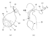
図1ないし図7は本発明の第1実施形態に係り、図1は本発明の医療用カプセル内視鏡を示す図、図2は医療用カプセル内視鏡の経口カプセル部と牽引保護管との連結構造を説明する図、図3は経口カプセル部の構成を説明する図、図4は発光部の構成を説明する図、図5は発光部の他の構成を説明する図、図6は医療用カプセル内視鏡を備えた内視鏡システムを説明する図、図7は医療用カプセル内視鏡の作用を説明する図である。
【0013】
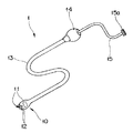
図1に示すように本実施形態の医療用カプセル内視鏡(以下カプセル内視鏡と略記する)1はいわゆる電子内視鏡であり、観察機能手段として観察光学系11を構成する固体撮像素子(以下CCDとも記載する)2及び照明光学系12を構成する照明用白色LED(以下LEDとも記載する)3を内蔵した略楕円球状の経口カプセル部(経口カプセル部と略記する)10と、この経口カプセル部10に連結された外形寸法が前記経口カプセル部10より小径で柔軟かつ引張強度に優れたチューブ状部材である牽引保護管13と、この牽引保護管13の基端に配設された把持部14と、この把持部14の端部から延出して基端部に電気コネクタ15aを備えた電気ケーブル15とで主に構成されている。
【0014】
図2に示すように略楕円球状の経口カプセル部10は、先端側を構成する曲面形状部を有する透明カバー部21と、この透明カバー部21の基端側に水密に接続固定されるカプセル本体22とで構成され、このカプセル本体22の基端部に中心軸と略一致するように形成した連結固定部22a(図3参照)に前記牽引保護管13の先端部が連結固定されるようになっている。
【0015】
図3に示すように前記カプセル本体22の基端側の外形形状は、牽引保護管13が接続される連結固定部22a近傍からカプセル本体22の先端側に向かうにしたがって外形寸法が略連続的に大径にそして滑らかに変化する外形形状変化部22bとして形成されている。つまり、経口カプセル部10と牽引保護管13との間の外形形状は、少なくとも直線部と連結固定部22aからカプセル本体22の先端側に向かうにしたがって外形寸法が連続的に大径に変化する部分とで構成され、かつ引っかかり部のない形状になっている。そして、前記カプセル本体22と前記牽引保護管13との固定部は水密構造になっている。
【0016】
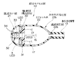
前記経口カプセル部10を構成する透明カバー部21の断面形状はドーム形状であり、この開口部と前記カプセル本体22の大径開口部との接続部分には観察部構成部材30の太径部31が補強部材の役割を兼ねて配置されている。
【0017】
前記観察部構成部材30は、太径部31と細径部32とを備え、断面形状が略凸字形状で中央部に貫通孔33を形成している。この貫通孔33の基端部には前記観察光学系を構成するCCD2が配置され、このCCD2の前方側にはCCD撮像面に観察像を結像させるための例えば非球面対物レンズ34,34を複数配設している。これら非球面レンズ34,34を用いることで、レンズ枚数を減らせるのでカプセル部の全長を短くして、嚥下性が向上する。また、太径部31の前面側には前記細径部32の周囲を等間隔に囲むように複数のLED3,…,3を配置している。
【0018】
そして、前記CCD2から延出する信号線16及び前記LED3から延出する電力線17は、前記カプセル本体22、牽引保護管13及び電気ケーブル15内を挿通して電気コネクタ15aまで延出している。この電気コネクタ15aは、前記CCD2の駆動及びこのCCD2から出力される信号の処理を行うCCD用回路や前記LED3への電力の供給を行う光源用回路等を備えた電装装置に接続されるようになっている。
【0019】
なお、図4に示すように前記LED3は、例えばケース体41に形成されている凹部42の底面に配置され、この凹部42内に前記LED3を埋めこむように蛍光剤43を充填した発光部40として構成されており、この発光部40を前記太径部31に配置している。なお、この発光部40は、破線に示す発光角θで照明光を発するように形成してある。これにより、従来のライトガイドファイバによる照明で発光角を広げるために用いていたレンズを不用にでき、カプセル部全長を短くして、嚥下性が向上する。
【0020】
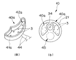
また、前記図4に示した発光部40を構成する代わりに、図5(a)に示すように配置位置関係等を考慮した形状のケース体41aを形成し、このケース体41の底部に複数のLED3,…,3を配置し、凹部42a内に上述と同様に蛍光剤43を充填して発光部40aを構成するようにしてもよい。このことにより、図5(b)に示すように観察光学系と照明光学系との配置構成を所望の位置構成にして、観察性能の向上や例えば破線に示すように処置具等を配置するため等の空間部45を設けることも可能になる。
【0021】
さらに、前記図3に示した透明カバー部21、カプセル本体22で構成される経口カプセル部10の表面及び前記牽引保護管13の表面に潤滑性材料である親水性ポリマーコートを施している。このことにより、経口カプセル部10を嚥下した際、人体の水分と親水性ポリマーとが結合して、前記経口カプセル部10及び牽引保護管13の表面に水の膜が形成されて管腔との間の潤滑性が向上する。
【0022】
上述のように構成したカプセル内視鏡1の作用を説明する。
前記カプセル内視鏡1を備えた内視鏡システムについて説明する。
【0023】
図6に示すように前記カプセル内視鏡1は、CCD2の駆動及び出力される信号の処理及びLED3への電力の供給を行う電装装置である例えば携帯型電装装置50と組み合わせて内視鏡システムを構成する。この携帯型電装装置50は、前記電気コネクタ16aとの接続部51を備え、前記CCD2で撮像した内視鏡画像が液晶モニタ52上に表示される構成である。
【0024】
前記携帯型電装装置50は、他に操作パネル53や内視鏡画像を撮影記録するためのシャッタボタン54、ビデオ出力端子55等を備え、このビデオ出力端子55に接続されるTVケーブル55aを介して例えば家庭用TV56の画面上に内視鏡画像を表示させることや、この家庭用VTR57を介してビデオテープ57aに検査経過の記録を行うことが可能になっている。また、内視鏡画像の撮影記録は、例えばコンパクトフラッシュ(登録商標)58などの記憶媒体で行われる。そして、前記携帯型電装装置50は、商用電源又は家庭用電源、電池59などのバッテリー等によって駆動される。
【0025】
ここで、上述した内視鏡システムで食道癌の早期発見のための内視鏡検査について説明する。
まず、医師は、前記内視鏡システムを用意し、検査を希望する被検者の自宅を訪問する。そこで、内視鏡検査を行うためカプセル内視鏡1と携帯型電装装置50とを接続する等の準備を行う。
【0026】
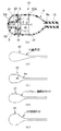
次に、セデーションを施すことなく、被検者に経口カプセル部10を錠剤を飲むように嚥下してもらう。すると、食道内の水分とカプセル内視鏡1の表面の親水性ポリマーとが結合して、経口カプセル部10が胃に向かって食道内をスムーズに移動していく。そして、携帯型電装装置50の液晶モニタ52又は家庭用TV56の画面上に表示される内視鏡画像を観察している医師が、図7(a)に示すように経口カプセル部10が食道を通過して胃まで到達したことを確認したなら、矢印に示すように牽引保護管13を手元側に引き戻す操作を行う。
【0027】
このとき、経口カプセル部10と牽引保護管13との間に外形寸法が略連続的に滑らかに大径に変化する外形形状変化部22bが設けられているので、図7(b)に示すように牽引保護管13、経口カプセル部10がスムーズに噴門を通過していく。このことによって、経口カプセル部10が食道に配置される。
【0028】
この状態から、再びゆっくりと前記牽引保護管13を手元側に引き戻し操作する。このとき、食道の水分とカプセル内視鏡1の表面の親水性ポリマーとが結合しているので、食道内をスムーズに移動して、良好な内視鏡像が液晶モニタ52に表示される。
【0029】
そして、検査終了後、携帯型電装装置50の接続部51から電気コネクタ15aを外し、使用済みのカプセル内視鏡1と携帯型電装装置50とを分離して、内視鏡システムを持ちかえる。なお、持ち帰ったカプセル内視鏡1は、洗滌消毒して再使用が可能になる。また、このカプセル内視鏡1は、通常の内視鏡同様、手術室での使用も可能である。
【0030】
このように、観察機能手段として観察光学系及び照明光学系を備えた経口カプセル部と、信号線及び電力線を内挿した細径の牽引保護管との間に段部がなく、滑らかに形状が変化する外形形状変化部を設けてカプセル内視鏡を構成したことにより、嚥下されて胃まで到達した経口カプセル部を牽引保護管を引き戻し操作して食道に引き戻す際、この経口カプセル部が噴門に引っかかることなく、スムーズに食道に再配置して引き戻し操作を行いながら食道の検査をすることができる。このことによって、被検者にセデーションを施すことなく、被検者のリラックスできる自宅で容易に食道癌の早期検査を行える。また、経口カプセル部の目的部位までの導入が被検者の嚥下によって行われるので、例えば内視鏡検査技師等の医療関係者によってもカプセル内視鏡を用いた内視鏡検査を容易に行えるので、例えば医療関係者が検査経過をビデオテープ等に記録し、病院に持ち帰ることによって、担当医は病院に居ながらにして診断を下すことが可能になる。
【0031】
また、経口カプセル部を構成する透明カバー部及びカプセル本体の表面及び牽引保護管の表面に親水性ポリマーコートを施したことによって、管腔との間の潤滑性を大幅に向上させることができる。このことによって、経口カプセル部の嚥下及び経口カプセルを胃から再び食道を介しての回収をスムーズに行える。
【0032】
なお、本実施形態においては前記経口カプセル部10の外形形状を構成する際、カプセル本体22に外形形状変化部22bを形成したが、例えば図8(a)の経口カプセル部の他の構成を示す図のように前記カプセル本体22の外形形状変化部22bと外形形状が略同形状で連結固定部9aを備えた連結部材9を形成して、この連結部材9を介してカプセル本体22Aと牽引保護管13とを連結する構成にしてもよい。このとき、前記カプセル本体22Aに対して前記太径部31及び細径部32を備えた前記観察部構成部材30を一体的に構成し、前記CCD2,レンズ34,34、発光部40を配置しておく。
【0033】
また、前記経口カプセル部10の外形形状も連結固定部からカプセル本体の先端側に向かうにしたがって外形寸法が連続的に滑らかに大径に変化する外形形状変化部に限定されるものではなく、例えば図8(b)の外形形状部の1例を示す図のように外形形状変化部を直線的に変化する円錐形状で形成したり、図8(c)の外形形状部の他の例を示す図のように2つの曲面の組合せで形成したり、図8(d)の外形形状部の別の例を示す図のようにシグモイド関数的に変化する形状で形成したり、図8(e)の外形形状部のまた他の例を示す図のように放物線形状で変化する形状で形成するようにしてもよい。
【0034】
図9は本発明の第2実施形態に係る経口カプセル部の別の構成を説明する図である。なお、図9(a)は経口カプセル部の構成を示す図、図9(b)は作用を説明する図である。
【0035】
図9(a)のに示すように本実施形態の経口カプセル部10Aは、前記第1実施形態に示したように先端部に位置していた観察光学系11及び照明光学系12を牽引保護管13が連結固定される側に設けている。このことにより、図9(b)に示すように嚥下されて胃まで到達した経口カプセル部を牽引保護管を引き戻す操作を行って食道に引き戻す際、観察範囲が経口カプセル部10Aの後端部側になって噴門の検査を行うことが可能になるとともに、前記経口カプセル部10Aをスムーズに食道に再配置して引き戻し操作をしながら食道の検査を行える。なお、上述のように経口カプセル部10Aを構成するとき、前記牽引保護管13との連結固定部を透明カバー部21Aに設けている。そして、牽引保護管13の中心軸と透明カバー部21Aの中心軸とが異なる位置関係で構成してある。その他の構成は前記第1実施形態と同様である。
【0036】
このように、観察光学系及び照明光学系を牽引保護管が連結固定される側に設けて経口カプセル部を構成したことにより、胃まで到達した経口カプセル部を食道に引き戻す操作を行った際に噴門の検査を行うことができる。その他の作用及び効果は前記第1実施形態と同様である。
【0037】
なお、図10(a)の経口カプセル部のまた他の構成を示す図のように観察光学系11及び照明光学系12を先端部及び基端部の両方に設けて経口カプセル部10Bを構成して、同図(b)の作用を説明する図に示すように経口カプセル部10Bの前方側及び後方側の観察を行えるようにしてもよい。
【0038】
また、図11(a)の側面に複数の観察機能手段を設けた経口カプセル部の図に示すように側周面を構成するカプセル本体22Aに複数の観察光学系11及びそれら観察光学系11に対応する照明光学系12を設けて経口カプセル部10Cを構成するようにしてもよい。このことによって、経口カプセル部10Cの前方側及び後方側の観察に加えて側方の観察も可能になる。また、図11(b)の側面に1つの観察機能手段を設けた経口カプセル部の図に示すように側周面を構成するカプセル本体22Aに複数の観察光学系11及びそれら観察光学系11に対応する照明光学系12を設ける代わりに、1つの観察光学系11及び照明光学系12を設け、そのカプセル本体22Aを回転自在にして経口カプセル部10Dを構成するようにしてもよい。このことによって、経口カプセル部10Dの前方側及び後方側の観察に加えて、1つの観察光学系で側方全周の観察を行える。また、図11(c)の側面に他の観察機能手段を設けた経口カプセル部の図に示すように側周面を構成するカプセル本体22Aに複数のアレイ素子を配設した超音波観測部29を設けて経口カプセル部10Eを構成するようにしてもよい。このことによって、経口カプセル部10Eの前方側及び後方側の観察を内視鏡画像によって行えるとともに側方の観察を超音波画像によって行える。
【0039】
さらに、図12(a)の湾曲部を設けたカプセル内視鏡の図に示すようにカプセル内視鏡1Aを、前記カプセル本体22と前記牽引保護管13との間に、従来の細径の内視鏡と同様に湾曲駒を連設して構成した湾曲部4を設け、この湾曲部4を操作する湾曲操作ノブ5を把持部14に設けて構成してもよい。このとき、湾曲操作ワイヤは牽引保護管13の貫通孔に配置される。このことにより、図12(b)の作用を説明する図に示すように経口カプセル部10が胃に到達した状態で、湾曲部4を湾曲させることによって噴門の検査を行える。
【0040】
図13は本発明の第3実施形態に係るカプセル内視鏡の別の構成を説明する図である。なお、図13(a)は硬度可変機構を有するカプセル内視鏡を説明する図、図13(b)は硬度可変機構を説明する図、図13(c)は本実施形態の作用を説明する図である。
図13(a)に示すように本実施形態のカプセル内視鏡1Bは、牽引保護管13の硬度を変化させる硬度可変機構として硬度可変装置6を具備している。この硬度可変装置6は、同図(b)に示すように前記牽引保護管13の貫通孔内に配置される硬度変化部61と、前記把持部14の例えば基端部に配置される硬度調整部65とで構成されている。
【0041】
前記硬度変化部61は、先端側に配置された先端形成部材62と、この先端形成部材62に一端部を固定したコイルシース63と、このコイルシース63内に挿通配置されて一端部を前記先端形成部材62に固定したワイヤ64とで構成されている。
【0042】
一方、前記硬度調整部65は、前記コイルシース63の他端部が固定され前記把持部14に一体的に固定配置される略パイプ形状で基端部外周側に雄ネジ部を形成したコイル固定部材66と、このコイル固定部材66の雄ネジ部に螺合する雌ネジ部を有して進退自在な調整ツマミ67と、前記ワイヤ64の他端部を固定保持して前記調整ツマミ67の基端部に配置されるワイヤ固定部材68とで構成されてる。
【0043】
このため、経口カプセル部10が胃に到達した状態で、前記調整ツマミ67を操作して前記ワイヤ固定部材68を矢印方向に移動させることによって、コイルシース63が収縮して牽引保護管13の硬度が変化させて例えば、図13(c)に示すように牽引保護管13の硬度を硬状態にして幽門近傍の検査も行える。また、牽引保護管13の硬度を硬状態に変化させておくことにより、カプセル内視鏡1の押し込みによる挿入が可能になる。
【0044】
なお、前記牽引保護管13の硬度を可変させる硬度可変機構としては上述した硬度可変装置6に限定されるものではなく、例えば牽引保護管13の貫通孔に図14(a)の硬度可変機構の他の構成を説明する図に示すすように細長で膨縮自在なバルーン7を配置するものであってもよい。前記バルーン7への送気は把持部14に設けた送気口71に接続される送気チューブ72を介して送気装置73によって行う。このため、図14(b)の作用を説明する図に示すように牽引保護管13内の所定位置に予め配置されているバルーン7内に供給する空気の量を適宜調整することによって、つまり、バルーン7の膨縮状態を変化させて牽引保護管13の硬度を所望の状態に調整して挿入及び検査を行える。
【0045】
また、上述したように牽引保護管13の貫通孔内に挿通配置するものとしては前記硬度可変装置6の硬度変化部61やバルーン7等に限定されるものではなく、例えば貫通孔内に送水チューブを設けるようにしてもよい。
【0046】
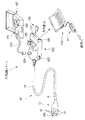
そして、この送水チューブを貫通孔内に設ける際には図15(a)のと遂行を有するカプセル内視鏡の構成を示す図のようにカプセル本体22の側周面や牽引保護管13の中途部側周面に複数の吐水孔75,…,75を形成してカプセル内視鏡1Cを構成する。このことにより、図15(b)の作用を説明する図に示すように経口カプセル部10を嚥下した状態で、把持部の送水口76に連結した送水用シリンジ77によって送水を行うことによって、この送水用シリンジ77によって送り込まれた水が吐水孔75,…,75から経口カプセル部10及び牽引保護管13の表面に流れ出て、これら経口カプセル部10及び牽引保護管13の表面にコーティングされている親水性ポリマーと結合して潤滑性能を向上させるとともに、吐水される水が潤滑剤の役割を果たす。
【0047】
さらに、図16に示すように経口カプセル部81と牽引保護管82との間に大きな段差部83のあるカプセル内視鏡80に対しては、この経口カプセル部81と牽引保護管82とを覆うカプセル用カバー85を取り付ける。
【0048】
前記カプセル用カバー85は、経口カプセル部81の少なくとも一部を覆うように配置されるカプセルカバー部86と、牽引保護管82を覆い包む挿入部カバー部87とで構成され、前記カプセルカバー部86と前記挿入部カバー部87との間には上述したように外形寸法が略連続的に滑らかに変化する外形形状変化部88を設けている。
【0049】
このことにより、経口カプセル部81と牽引保護管82との間に大きな段差部83のあるカプセル内視鏡80を使用する際、前記カプセル用カバー85を被せることによって、嚥下性の向上を図れる。なお、このカプセル用カバー85のカプセルカバー部86及び挿入部カバー部87、外形形状変化部88の表面に親水性ポリマーをコーティングを施したり、挿入部カバー部87に前述した硬度可変装置6や送水チューブを設ける構成であってもよい。
【0050】
図17は本発明の第4実施形態に係り、図17は処置具挿通用のチャンネルチューブを有するカプセル内視鏡の構成を説明する図である。図17(a)はカプセル内視鏡の構成を説明する図、図17(b)は牽引保護管の内部構成を説明する図、図17(c)は作用を説明する図である。
【0051】
図17(a)に示すように本実施形態のカプセル内視鏡1Dは、経口カプセル部90の先端側に処置具用開口91を有し、この処置具用開口91に後述する処置具挿通用のチャンネルチューブの一端部が連通している。そして、このチャンネルチューブの他端部は牽引保護管92の貫通孔を挿通して把持部14の例えば基端に設けられた図示しない処置具挿通口に連通している。
【0052】
図17(b)に示すように前記牽引保護管92は、一部に伸縮性部材93を配置して構成されており、貫通孔内には前記信号線16及び電力線17とともに押しつぶして開口部を塞いだ状態にしたチャンネルチューブ94が配置してある。
【0053】
このため、経口カプセル部90が胃に到達した状態のとき、図17(a)に示すように処置具を処置具挿通口から処置具用開口91に向けて挿入していくことにより、つぶれた状態のチャンネルチューブ94を図17(c)に示すように押し広げて処置具が進んでいく。このとき、牽引保護管92に設けられている伸縮性部材93も図17(c),(a)の破線に示すように広がって牽引保護管92が大径になる。その他の構成は上述した実施形態と同様であり、同部材には同符合を付して説明を省略する。
【0054】
このように、経口カプセル部を胃に到達させた後、牽引保護管に設けられているつぶされた状態のチャンネルチューブを介して処置具を目的部位に導入することによって、観察のみならず必要に応じて処置を行うこともできる。その他の作用及び効果は上述した実施形態と同様である。
【0055】
なお、前記実施形態においては牽引保護管の一部に伸縮性部材を設けてチャンネルチューブに処置具を挿通したとき牽引保護管が大径になるように構成したが、牽引保護管を以下のように構成しても同様の作用及び効果を得られる。
【0056】
図18(a)のカプセル内視鏡の他の構成を説明する図及び図18(b)の作用を説明する図に示すように、本実施形態においては牽引保護管92Aを体腔内温度で径寸法が大径になる形状記憶部材で形成している。その他の構成及び作用・効果は前記第4実施形態と同様である。なお、カプセル内視鏡を抜去する際にはチャンネルチューブ内に水を流し込んで牽引保護管92Aの径寸法を縮小する。
【0057】
また、図18(c)のカプセル内視鏡の別の構成を説明する図及び図18(d)の作用を説明する図に示すように、本実施形態においては牽引保護管92Bを体液、電流検知、ph値の変化で径寸法が大径になる膨張ポリマーで形成している。その他の構成及び作用・効果は前記第4実施形態と同様である。
【0058】
さらに、図18(e)の内径寸法d1 のチャンネル部を説明する図及び図18(f)の内径寸法d2 のチャンネル部を説明する図に示すように本実施形態においては前記牽引保護管92の内部にバルーンを螺旋状に形成したチャンネル部95を設けている。このチャンネル部95はバルーン内の圧力を変化させることによって内径寸法が変化する。このため、嚥下する際にはバルーン内に空気を送らず内径寸法を小径なd1 にしておき、処置具を挿通するときバルーンを加圧して内径寸法を大径なd2 にする。このことによって、チャンネル部95の内径が大きく広がって処置具の挿通が可能になる。
【0059】
又、図19(a)の処置具を有する経口カプセル部を説明する図に示すように経口カプセル部100に予め処置具101及び吸引チューブ102等を配置する処置具配置凹部103を設けてカプセル内視鏡1Eを構成するようにしてもよい。この処置具101の開閉動作は、図示しない把持部に設けた処置具操作ノブ(不図示)によって行えるようになっている。
【0060】
そして、前記処置具101は、経口カプセル部100を嚥下する際、口腔や喉、食道等に傷をつけることを防止するため、嚥下の際には図19(b)の嚥下状態の経口カプセル部を説明する図に示すように処置具101は閉じた状態であり、このとき処置具101の外形形状はすべて滑らかな曲面になっている。
【0061】
また、経口カプセル部10が胃に到達した状態で例えば処置すべき部位を発見した場合には、図20(a)の処置具挿通状態を示す図ないし図20(d)に示す連結部品110を順次処置具120及び牽引保護管13に配置して、図20(e)の処置具挿入状態を説明する図に示すように処置具120を目的部位に導入するようにしてもよい。
【0062】
図20(b)の連結部品の斜視図に示すように前記連結部品110は、口腔や喉、食道等に傷をつけることを防止するため外形形状はすべて滑らかな曲面で形成されている。そして、図20(c)の連結部品の正面図に示すようにこの連結部品110には、前記処置具120の挿入部121に付勢固定される処置具係入孔111と、前記牽引保護管13に沿って移動するように遊嵌配置される案内孔112と、前記処置具係入孔111及び案内孔112にそれぞれ形成されている接続溝114の開閉動作及び所定の固定力を発生させるための作用孔113とが設けられている。したがって、図20(d)の連結部品の作用を説明する図に示すように作用孔113の両側部を指で矢印方向に押圧することによって前記接続溝114が開状態になる。このとき、前記図20(a)に示すように処置具120の挿入部121及び牽引保護管13へ連結部品110を取り付けることが可能になる。
【0063】
つまり、処置すべき部位を術者が発見したとき、まず、連結部品110を処置具120の挿入部121及び牽引保護管13へ取り付ける。次に、この状態で処置具120を押し込み操作する。すると、案内孔112が牽引保護管13に遊嵌した状態であるので、連結部品110が牽引保護管13に沿って体腔内を移動することにより、処置具120が徐々に体腔内に向かって移動していく。そして、所定量の移動を行った段階で、新たな連結部品110を前記挿入部121及び牽引保護管13に取り付け、再び処置具120を押し込操作する。この一連の動作を繰り返し行うことによって、前記処置具120が前記図20(e)に示すように処置部位近傍まで導入されて、所望の処置を行える。
【0064】
ところで、上述した実施形態においては、内視鏡システムを、カプセル内視鏡1と携帯型電装装置50とで構成しているが、内視鏡システムを図21の内視鏡システムの他の構成を示す図のように構成するようにしてもよい。
【0065】
本実施形態における内視鏡システムは、図に示すように操作部付きカプセル内視鏡1Fと、送気送水装置付き収納ケース130と、検査データや画像データを記録・処理する携帯型コンピュータ140とを備えている。この内視鏡システムは、在宅検診は勿論、緊急検査、遠隔検診を可能にするものである。
【0066】
前記カプセル内視鏡1Fは、上述した構成と同様の経口カプセル部10と、この経口カプセル部10に連結された牽引保護管13とを備え、この牽引保護管13の基端には操作部122が配設されて、内視鏡を構成している。そして、前記経口カプセル部10と前記牽引保護管13との間には前記湾曲部4が設けられている。
【0067】
前記操作部122の外装部には前記湾曲部4を湾曲操作する操作ジョグ123や送気・送水プラグ124及び内視鏡画像を表示する液晶モニタ等の表示装置125、例えばスマートメディア(商標)等の記憶媒体126が配置される媒体配置部127、前記コンピュータ140と例えば赤外線通信によって接続するための接続部128が設けられている。そして、前記操作部122内には上述したCCD用回路や光源用回路等が備えられている。
【0068】
また、前記送気送水装置付き収納ケース130は、送気・送水用ポンプ131及びカプセル内視鏡収納部132が備えられており、前記送気・送水用ポンプ131から延出する送気・送水用チューブ133を前記送気・送水プラグ124に接続することによって、例えば洗滌ノズル129から水や空気等の流体を噴出できるようになっている。
【0069】
前記携帯型コンピュータ140には通信装置141の接続が可能であり、この通信装置141によって例えば病院内のコンピュータ(不図示)にカプセル内視鏡1Fで得た診断データや観察画像データを伝送することが可能になっている。
【0070】
つまり、本実施形態の内視鏡システムにおいては、経口カプセル部10の目的部位までの導入を内視鏡検査技師等の医療関係者によっても容易に行えるという利点とともに、担当医と医療関係者とが通信装置を介して検査データの受け渡しや意見の交換を行えるので、担当医は病院に居ながらにして所定の検査を行うことができる。
【0071】
また、内視鏡検査技師が何件かの家を訪問して、検査を行った後、病院内の担当医に記録媒体だけを渡すことによって、担当医は複数の患者の検査を集中して行えるので適切な診断を時間の無駄なく行うことができる。
【0072】
なお、本発明は、以上述べた実施形態のみに限定されるものではなく、発明の要旨を逸脱しない範囲で種々変形実施可能である。
【0073】
[付記]
以上詳述したような本発明の上記実施形態によれば、以下の如き構成を得ることができる。
【0074】
(1)目視観察を行う観察機能手段を少なくとも1つ配設した小径粒状の経口カプセル部と、
この経口カプセル部の一端部から延出して、前記経口カプセル部を手元側へ引き寄せる牽引部材及び前記観察機能手段に接続される電気ケーブルを保護する保護部材を兼ね、前記経口カプセルの最大外径寸法より細径で柔軟な牽引保護管とを具備し、
前記牽引保護管と前記経口カプセル部とを結ぶ連結部の外形形状は、この経口カプセル部から前記牽引保護管に向かって略連続的に小径に変化し、且つその変化する表面が滑らかである医療用カプセル内視鏡。
【0075】
(2)前記経口カプセル部の外形寸法を、セデーションを施すことなく嚥下可能な大きさに設定した付記1記載の医療用カプセル内視鏡。
【0076】
(3)前記経口カプセル部、牽引保護管及び連結部分の外表面に潤滑性材料を設けた付記1記載の医療用カプセル内視鏡。
【0077】
(4)前記観察機能手段は、観察部位を照明するLEDと、このLEDによって照らされた観察部位の光学像を電気信号に光電変換する撮像素子とを有する付記1記載の医療用カプセル内視鏡。
【0078】
(5)前記観察機能手段を、前記牽引保護チューブが連結されている端部側又はその反対の端部側の少なくとも一方に設けた付記1記載の医療用カプセル内視鏡。
【0079】
(6)前記観察機能手段を、さらに、側周の観察を可能にする側周面部に設けた付記1記載の医療用カプセル内視鏡。
【0080】
(7)前記経口カプセル部に、観察機能手段としてさらに超音波観察部を設けた付記4記載の医療用カプセル内視鏡。
【0081】
(8)前記連結部の外径形状が円錐形状である付記1記載の医療用カプセル内視鏡。
【0082】
(9)前記連結部を2つの曲面で構成した付記1記載の医療用カプセル内視鏡。
【0083】
(10)前記連結部の外径形状は、関数的に変化する形状である付記1記載の医療用カプセル内視鏡。
【0084】
(11)前記連結部の外径形状は、放物線形状である付記1記載の医療用カプセル内視鏡。
【0085】
(12)前記牽引保護管と前記経口カプセル部との間に湾曲部を設けた付記1記載の医療用カプセル内視鏡。
【0086】
(13)前記牽引保護管に硬度可変機構を設けた付記1記載の医療用カプセル内視鏡。
【0087】
(14)前記硬度可変機構は、硬度変化部と硬度調整部とを有する硬度可変装置である付記13記載の医療用カプセル内視鏡。
【0088】
(15)前記硬度可変機構は、膨縮自在なバルーンである付記14記載の医療用カプセル内視鏡。
【0089】
送水チューブ
(16)前記牽引保護管に送水チューブを設け、カプセル本体の側周面及び牽引保護管の中途部側周面に、前記送水チューブによって送られる液体を吐出する複数の吐水孔を設けた付記1記載の医療用カプセル内視鏡。
【0090】
(17)前記牽引保護管に処置具を挿通するチャンネルチューブを設けた付記1記載の医療用カプセル内視鏡。
【0091】
(18)前記経口カプセル部に処置具を一体的に配置した付記1記載の医療用カプセル内視鏡。
【0092】
【発明の効果】
以上説明したように本発明によれば、セデーションを施すことなく嚥下が容易で、胃内に到達した経口カプセル部を引き戻す操作を確実且つ容易に行え、在宅検査に使用可能な医療用カプセル内視鏡を提供することができる。
【図面の簡単な説明】
【図1】図1ないし図7は本発明の第1実施形態に係り、図1は本発明の医療用カプセル内視鏡を示す図
【図2】医療用カプセル内視鏡の経口カプセル部と牽引保護管との連結構造を説明する図
【図3】経口カプセル部の構成を説明する図
【図4】発光部の構成を説明する図
【図5】発光部の他の構成を説明する図
【図6】医療用カプセル内視鏡を備えた内視鏡システムを説明する図
【図7】医療用カプセル内視鏡の作用を説明する図
【図8】経口カプセル部の他の構成及び外形形状部の形状を具体的に説明する図
【図9】本発明の第2実施形態に係る経口カプセル部の別の構成及び作用を説明する図
【図10】経口カプセル部のまた他の構成及び作用を説明する図
【図11】経口カプセル部のまた別の構成を説明する図
【図12】医療用カプセル内視鏡の他の構成及び作用を説明する図
【図13】本発明の第3実施形態に係る硬度可変機構を有するカプセル内視鏡の構成及び作用を説明する図
【図14】硬度可変機構の他の構成及び作用を説明する図
【図15】送水チューブを有するカプセル内視鏡の構成例及び作用を説明する図
【図16】カプセル用カバーを説明する図
【図17】処置具挿通用のチャンネルチューブを有するカプセル内視鏡の構成及び作用を説明する図
【図18】処置具挿通用のチャンネルチューブを有するカプセル内視鏡の他の構成及び作用を説明する図
【図19】処置具を有する経口カプセル部を示す図
【図20】連結部品を使用して処置具を体腔内に導く状態を説明する図
【図21】内視鏡システムの他の構成を示す図
【符号の説明】
2…CCD
3…LED
10…経口カプセル部
13…牽引保護管
30…観察部構成部材
21…透明カバー部
22…カプセル本体
22b…外形形状変化部
22a…連結固定部[0001]
BACKGROUND OF THE INVENTION
The present invention relates to a medical capsule endoscope that is sent into a living body by swallowing a patient, and observes the esophagus and stomach and performs medical treatment.
[0002]
[Prior art]
In recent years, by inserting a scope into a body cavity, the gastrointestinal tract such as the esophagus, stomach, small intestine, and large intestine, and the trachea such as the lung are observed, and various treatment tools are inserted using the treatment instrument channel as necessary. Endoscopes that can be treated are used. In particular, an electronic endoscope using an electronic imaging device such as a charge coupled device (CCD) is widely used because it can display an image on a monitor and there is less fatigue of an operator who operates the endoscope.
[0003]
The endoscopy is generally performed in an operating room equipped with a light source device that supplies illumination light and a camera control unit that processes image signals transmitted from an electronic endoscope. It was.
[0004]
In addition, when an endoscope is inserted orally, the subject is generally held by a mouthpiece, and after sedation is administered to reduce patient pain, the insertion part is inserted into the body cavity. It was pushed to the target site and was observed and treated.
[0005]
On the other hand, for the purpose of reducing pain and diagnosing and treating patients, for example, a capsule incorporating a measuring instrument or wireless device is swallowed, and the pH value in the body cavity is transmitted outside the body in the process of passing through the stomach and intestine In recent years, a number of medical capsule devices or the like that directly perform drug application have been proposed.
[0006]
As one of medical capsule devices, Japanese Patent Laid-Open No. 2-224650 discloses an ultrasonic transducer, an ultrasonic drive means, a means for scanning an ultrasonic beam, and an ultrasonic reflected signal converted into an electrical signal. An ultrasonic diagnostic medical capsule having a transmission means for leading out of the body is shown.
[0007]
[Problems to be solved by the invention]
However, in the ultrasonic diagnostic medical capsule disclosed in JP-A-2-224650, the oral capsule portion formed in a spherical shape or the like in which the ultrasonic transducer is disposed and the transmission means are inserted. Since a step was formed between the connecting part and the wired part, when pulling back the oral capsule part that reached the stomach, the oral capsule part caught on the cardia, prolonging the examination time, or In order to remove the cable, a load more than necessary is applied to the wired part, which may cause a problem in the transmission means.
[0008]
In addition, there has been a demand for an endoscope that can be used not only for the purpose of reducing pain for patients but also for visiting elderly people and children.
[0009]
The present invention has been made in view of the above circumstances, and can be swallowed easily without giving a foundation, and can be used to perform an operation for pulling back an oral capsule portion that has reached the stomach reliably and easily, and can be used for home examinations. It aims to provide a capsule endoscope.
[0010]
The medical capsule endoscope according to one aspect of the present invention includes an oral capsule portion provided with at least one observation function means for observing an examination site, and extends from one end portion of the oral capsule portion. A traction member that draws the portion toward the hand side, and a traction protection tube that also serves as a protection member that protects the electric cable connected to the observation function means, A hydrophilic polymer is provided on the outer surface of the oral capsule part and the traction protective tube, and the oral capsule part Connected to the traction protection tube To do Outline of Size Is characterized in that the diameter gradually changes from the oral capsule portion toward the traction protection tube.
[0011]
According to this configuration, when pulling back the traction protection tube and performing the pull-back operation of the oral capsule portion, the outer shape of the connecting portion between the oral capsule portion and the traction protection tube changes smoothly. Can be moved smoothly without being caught by the cardia.
[0012]
DETAILED DESCRIPTION OF THE INVENTION
Embodiments of the present invention will be described below with reference to the drawings.
1 to 7 relate to a first embodiment of the present invention, FIG. 1 is a view showing a medical capsule endoscope of the present invention, and FIG. 2 is an oral capsule portion and a traction protection tube of the medical capsule endoscope. FIG. 3 is a diagram illustrating the configuration of the oral capsule unit, FIG. 4 is a diagram illustrating the configuration of the light emitting unit, FIG. 5 is a diagram illustrating another configuration of the light emitting unit, and FIG. FIG. 7 is a diagram for explaining an endoscope system including a medical capsule endoscope, and FIG. 7 is a diagram for explaining an operation of the medical capsule endoscope.
[0013]
As shown in FIG. 1, a medical capsule endoscope (hereinafter abbreviated as “capsule endoscope”) 1 of this embodiment is a so-called electronic endoscope, and constitutes an observation
[0014]
As shown in FIG. 2, the substantially oval
[0015]
As shown in FIG. 3, the outer shape of the base end side of the
[0016]
The cross-sectional shape of the
[0017]
The observation
[0018]
The
[0019]
As shown in FIG. 4, the
[0020]
Further, instead of configuring the
[0021]
Furthermore, a hydrophilic polymer coat, which is a lubricating material, is applied to the surface of the
[0022]
The operation of the
An endoscope system including the
[0023]
As shown in FIG. 6, the
[0024]
The portable
[0025]
Here, an endoscopy for early detection of esophageal cancer using the above-described endoscope system will be described.
First, a doctor prepares the endoscope system and visits the home of a subject who desires an examination. Therefore, preparations such as connection between the
[0026]
Next, without subjecting the subject, the subject is swallowed to drink the tablet of the
[0027]
At this time, an outer
[0028]
From this state, the
[0029]
And after completion | finish of a test | inspection, the
[0030]
In this way, there is no step between the oral capsule portion provided with the observation optical system and the illumination optical system as the observation function means, and the thin traction protective tube with the signal line and the power line inserted, and the shape is smoothly formed. By configuring the capsule endoscope with a changing external shape changing part, when the oral capsule part swallowed and reached the stomach is pulled back to the esophagus by pulling back the traction protection tube, this oral capsule part becomes the cardia Without being caught, the esophagus can be inspected while smoothly rearranging the esophagus and performing a pull-back operation. As a result, early examination of esophageal cancer can be easily performed at a home where the subject can relax without giving the subject a need for a foundation. In addition, since the introduction of the oral capsule part to the target site is performed by swallowing the subject, for example, endoscopy using a capsule endoscope can be easily performed by medical personnel such as an endoscopy engineer. Therefore, for example, a medical staff records the examination progress on a video tape or the like and takes it back to the hospital, so that the doctor in charge can make a diagnosis while staying in the hospital.
[0031]
Moreover, the lubricity between the lumen and the lumen can be greatly improved by applying a hydrophilic polymer coat to the surface of the transparent cover portion, capsule body and traction protective tube constituting the oral capsule portion. As a result, swallowing of the oral capsule part and recovery of the oral capsule from the stomach through the esophagus can be performed smoothly.
[0032]
In the present embodiment, when the outer shape of the
[0033]
Further, the outer shape of the
[0034]
FIG. 9 is a diagram illustrating another configuration of the oral capsule unit according to the second embodiment of the present invention. FIG. 9A is a diagram showing the configuration of the oral capsule part, and FIG. 9B is a diagram for explaining the action.
[0035]
As shown in FIG. 9 (a), the
[0036]
In this way, when the observation optical system and the illumination optical system are provided on the side where the traction protection tube is connected and fixed, and the oral capsule part is configured, when the operation of returning the oral capsule part reaching the stomach to the esophagus is performed. Cardiac examination can be performed. Other operations and effects are the same as those in the first embodiment.
[0037]
As shown in FIG. 10A, which shows another configuration of the oral capsule portion, the observation
[0038]
Moreover, as shown in the figure of the oral capsule part which provided the some observation function means in the side surface of Fig.11 (a), in the capsule
[0039]
Further, as shown in the capsule endoscope provided with the curved portion in FIG. 12A, the capsule endoscope 1A is placed between the
[0040]
FIG. 13 is a diagram illustrating another configuration of the capsule endoscope according to the third embodiment of the present invention. 13A illustrates a capsule endoscope having a hardness varying mechanism, FIG. 13B illustrates a hardness varying mechanism, and FIG. 13C illustrates the operation of the present embodiment. FIG.
As shown in FIG. 13A, the
[0041]
The
[0042]
On the other hand, the
[0043]
For this reason, when the
[0044]
The hardness variable mechanism that varies the hardness of the
[0045]
Further, as described above, what is inserted and disposed in the through hole of the
[0046]
When the water supply tube is provided in the through hole, the side peripheral surface of the capsule
[0047]
Further, as shown in FIG. 16, for the
[0048]
The
[0049]
Accordingly, when using the
[0050]
FIG. 17 is related to 4th Embodiment of this invention, FIG. 17 is a figure explaining the structure of the capsule endoscope which has a channel tube for treatment instrument penetration. FIG. 17A is a diagram illustrating the configuration of the capsule endoscope, FIG. 17B is a diagram illustrating the internal configuration of the traction protection tube, and FIG. 17C is a diagram illustrating the operation.
[0051]
As shown in FIG. 17A, the capsule endoscope 1D of the present embodiment has a treatment instrument opening 91 on the distal end side of the
[0052]
As shown in FIG. 17 (b), the
[0053]
For this reason, when the
[0054]
In this way, after the oral capsule part reaches the stomach, the treatment tool is introduced into the target site via the collapsed channel tube provided in the traction protection tube, so that it becomes necessary not only for observation. Treatment can be performed accordingly. Other operations and effects are the same as those of the above-described embodiment.
[0055]
In the above embodiment, a stretchable member is provided on a part of the traction protection tube so that the traction protection tube has a large diameter when the treatment instrument is inserted into the channel tube. Even if configured, the same operation and effect can be obtained.
[0056]
As shown in the drawing for explaining another configuration of the capsule endoscope in FIG. 18 (a) and the drawing for explaining the operation in FIG. 18 (b), in this embodiment, the
[0057]
Further, as shown in FIG. 18C, a diagram illustrating another configuration of the capsule endoscope, and a diagram illustrating the operation of FIG. 18D, in this embodiment, the
[0058]
Furthermore, as shown in FIG. 18 (e), which is a diagram for explaining the channel portion having the inner diameter dimension d1, and in FIG. 18 (f), which is for explaining the channel portion having the inner diameter dimension d2, in the present embodiment, A
[0059]
Further, as shown in the drawing for explaining the oral capsule portion having the treatment tool of FIG. 19A, the
[0060]
When the swallowing of the
[0061]
Further, when a site to be treated is found in a state where the
[0062]
As shown in the perspective view of the connecting part in FIG. 20 (b), the connecting
[0063]
That is, when the surgeon finds a site to be treated, first, the connecting
[0064]
Incidentally, in the above-described embodiment, the endoscope system is configured by the
[0065]
As shown in the figure, the endoscope system according to the present embodiment includes a capsule endoscope 1F with an operation unit, a
[0066]
The capsule endoscope 1F includes an
[0067]
A
[0068]
The
[0069]
A
[0070]
In other words, in the endoscope system of the present embodiment, the medical doctor and medical personnel can easily introduce the
[0071]
In addition, after an endoscopist visits several houses and conducts an examination, the doctor in charge concentrates the examination of multiple patients by giving only the recording medium to the doctor in charge in the hospital. This makes it possible to make an appropriate diagnosis without wasting time.
[0072]
It should be noted that the present invention is not limited to the embodiments described above, and various modifications can be made without departing from the spirit of the invention.
[0073]
[Appendix]
According to the embodiment of the present invention as described above in detail, the following configuration can be obtained.
[0074]
(1) a small-diameter granular oral capsule portion provided with at least one observation function means for performing visual observation;
Extending from one end portion of the oral capsule portion, serving as a protective member for protecting the electric cable connected to the traction member and the observation function means for pulling the oral capsule portion to the hand side, the maximum outer diameter dimension of the oral capsule It has a traction protection tube with a smaller diameter and flexibility,
The external shape of the connecting portion connecting the traction protection tube and the oral capsule portion changes from the oral capsule portion to the traction protection tube almost continuously in a small diameter, and the changing surface is smooth. Capsule endoscope.
[0075]
(2) The medical capsule endoscope according to
[0076]
(3) The medical capsule endoscope according to
[0077]
(4) The medical capsule endoscope according to
[0078]
(5) The medical capsule endoscope according to
[0079]
(6) The medical capsule endoscope according to
[0080]
(7) The medical capsule endoscope according to
[0081]
(8) The medical capsule endoscope according to
[0082]
(9) The medical capsule endoscope according to
[0083]
(10) The medical capsule endoscope according to
[0084]
(11) The medical capsule endoscope according to
[0085]
(12) The medical capsule endoscope according to
[0086]
(13) The medical capsule endoscope according to
[0087]
(14) The hardness varying mechanism is a hardness varying device having a hardness varying portion and a hardness adjusting portion. 13 The medical capsule endoscope as described.
[0088]
(15) The medical capsule endoscope according to
[0089]
Water supply tube
(16)
[0090]
(17) The medical capsule endoscope according to
[0091]
(18) The medical capsule endoscope according to
[0092]
【The invention's effect】
As described above, according to the present invention, a medical capsule endoscope that can be swallowed easily without giving a foundation, and that can easily and easily pull back the oral capsule portion that has reached the stomach, and can be used for home examinations. A mirror can be provided.
[Brief description of the drawings]
FIG. 1 to FIG. 7 relate to a first embodiment of the present invention, and FIG. 1 is a view showing a medical capsule endoscope of the present invention.
FIG. 2 is a diagram for explaining a connection structure between an oral capsule portion of a medical capsule endoscope and a traction protection tube
FIG. 3 is a diagram illustrating the configuration of an oral capsule part
FIG. 4 is a diagram illustrating a configuration of a light emitting unit
FIG. 5 is a diagram illustrating another configuration of a light emitting unit.
FIG. 6 is a diagram illustrating an endoscope system including a medical capsule endoscope
FIG. 7 is a diagram illustrating the operation of a medical capsule endoscope
FIG. 8 is a diagram specifically explaining another configuration of the oral capsule portion and the shape of the outer shape portion.
FIG. 9 is a diagram illustrating another configuration and action of the oral capsule unit according to the second embodiment of the present invention.
FIG. 10 is a diagram for explaining another configuration and action of the oral capsule part;
FIG. 11 is a diagram illustrating another configuration of the oral capsule part
FIG. 12 is a diagram illustrating another configuration and operation of the medical capsule endoscope
FIG. 13 is a diagram illustrating the configuration and operation of a capsule endoscope having a hardness varying mechanism according to a third embodiment of the present invention.
FIG. 14 is a diagram illustrating another configuration and operation of the hardness varying mechanism.
FIG. 15 is a diagram illustrating a configuration example and an operation of a capsule endoscope having a water supply tube.
FIG. 16 is a diagram illustrating a capsule cover
FIG. 17 is a diagram illustrating the configuration and operation of a capsule endoscope having a channel tube for inserting a treatment instrument.
FIG. 18 is a diagram for explaining another configuration and operation of a capsule endoscope having a channel tube for inserting a treatment instrument.
FIG. 19 is a diagram showing an oral capsule portion having a treatment tool.
FIG. 20 is a diagram illustrating a state in which a treatment tool is guided into a body cavity using a connecting part.
FIG. 21 is a diagram showing another configuration of the endoscope system.
[Explanation of symbols]
2 ... CCD
3 ... LED
10. Oral capsule part
13 ... Traction protection tube
30 ... Observation member component
21 ... Transparent cover
22 ... Capsule body
22b ... Outer shape change part
22a ... Connection fixing part
Claims (13)
この経口カプセル部の一端部から延出して、前記経口カプセル部を手元側へ引き寄せる牽引部材及び前記観察機能手段に接続される電気ケーブルを保護する保護部材を兼ねる牽引保護管と、を具備し、
前記経口カプセル部及び前記牽引保護管の外表面に親水性ポリマーを設け、
さらに、前記牽引保護管に送水用のチューブを設け、カプセル本体の側周面あるいは牽引保護管の中途部側周面に、前記送水チューブによって送られる液体を吐出する複数の吐水孔を設け、
前記経口カプセル部の前記牽引保護管と連結する部分の外形寸法は、前記経口カプセル部から前記牽引保護管に向かって略連続的に小径に変化することを特徴とする医療用カプセル内視鏡。An oral capsule portion provided with at least one observation function means for obtaining an optical image of the examination site;
A traction protection tube that extends from one end of the oral capsule portion and serves also as a traction member that draws the oral capsule portion closer to the hand and a protective member that protects the electrical cable connected to the observation function means,
A hydrophilic polymer is provided on the outer surface of the oral capsule part and the traction protection tube,
Furthermore, a tube for water supply is provided in the traction protection tube, and a plurality of water discharge holes for discharging the liquid sent by the water supply tube are provided on the side peripheral surface of the capsule body or in the middle of the traction protection tube,
The medical capsule endoscope characterized in that an outer dimension of a portion of the oral capsule portion connected to the traction protection tube changes from the oral capsule portion to the traction protection tube in a substantially continuous small diameter.
Priority Applications (1)
| Application Number | Priority Date | Filing Date | Title |
|---|---|---|---|
| JP32022599A JP4472069B2 (en) | 1999-11-10 | 1999-11-10 | Medical capsule endoscope |
Applications Claiming Priority (1)
| Application Number | Priority Date | Filing Date | Title |
|---|---|---|---|
| JP32022599A JP4472069B2 (en) | 1999-11-10 | 1999-11-10 | Medical capsule endoscope |
Related Child Applications (1)
| Application Number | Title | Priority Date | Filing Date |
|---|---|---|---|
| JP2006314714A Division JP4505445B2 (en) | 2006-11-21 | 2006-11-21 | Medical capsule endoscope |
Publications (3)
| Publication Number | Publication Date |
|---|---|
| JP2001137182A JP2001137182A (en) | 2001-05-22 |
| JP2001137182A5 JP2001137182A5 (en) | 2006-12-28 |
| JP4472069B2 true JP4472069B2 (en) | 2010-06-02 |
Family
ID=18119132
Family Applications (1)
| Application Number | Title | Priority Date | Filing Date |
|---|---|---|---|
| JP32022599A Expired - Lifetime JP4472069B2 (en) | 1999-11-10 | 1999-11-10 | Medical capsule endoscope |
Country Status (1)
| Country | Link |
|---|---|
| JP (1) | JP4472069B2 (en) |
Families Citing this family (60)
| Publication number | Priority date | Publication date | Assignee | Title |
|---|---|---|---|---|
| US7813789B2 (en) | 1999-06-15 | 2010-10-12 | Given Imaging Ltd. | In-vivo imaging device, optical system and method |
| US7996067B2 (en) | 1999-06-15 | 2011-08-09 | Given Imaging Ltd. | In-vivo imaging device, optical system and method |
| US7119814B2 (en) | 2001-05-18 | 2006-10-10 | Given Imaging Ltd. | System and method for annotation on a moving image |
| IL143259A (en) | 2001-05-20 | 2006-08-01 | Given Imaging Ltd | Method for moving an object through the colon |
| JP2002360508A (en) * | 2001-06-08 | 2002-12-17 | Olympus Optical Co Ltd | Canal alimenta'rius inspection device |
| IL150167A (en) | 2001-06-11 | 2010-05-17 | Arkady Glukhovsky | Device for in vivo imaging |
| US7998065B2 (en) | 2001-06-18 | 2011-08-16 | Given Imaging Ltd. | In vivo sensing device with a circuit board having rigid sections and flexible sections |
| JP4794765B2 (en) * | 2001-07-30 | 2011-10-19 | オリンパス株式会社 | Capsule endoscope |
| US6951536B2 (en) | 2001-07-30 | 2005-10-04 | Olympus Corporation | Capsule-type medical device and medical system |
| US8428685B2 (en) | 2001-09-05 | 2013-04-23 | Given Imaging Ltd. | System and method for magnetically maneuvering an in vivo device |
| US6692431B2 (en) * | 2001-09-07 | 2004-02-17 | Smith & Nephew, Inc. | Endoscopic system with a solid-state light source |
| US6939290B2 (en) | 2002-02-11 | 2005-09-06 | Given Imaging Ltd | Self propelled device having a magnetohydrodynamic propulsion system |
| US6958034B2 (en) | 2002-02-11 | 2005-10-25 | Given Imaging Ltd. | Self propelled device |
| US7662094B2 (en) * | 2002-05-14 | 2010-02-16 | Given Imaging Ltd. | Optical head assembly with dome, and device for use thereof |
| ATE470391T1 (en) | 2002-08-13 | 2010-06-15 | Given Imaging Ltd | SYSTEM FOR SAMPLING AND ANALYSIS IN VIVO |
| US7662093B2 (en) | 2002-09-30 | 2010-02-16 | Given Imaging, Ltd. | Reduced size imaging device |
| AU2003269438A1 (en) | 2002-09-30 | 2004-04-19 | Given Imaging Ltd. | In-vivo sensing system |
| WO2004036803A2 (en) | 2002-10-15 | 2004-04-29 | Given Imaging Ltd. | Device, system and method for transfer of signals to a moving device |
| US7833151B2 (en) | 2002-12-26 | 2010-11-16 | Given Imaging Ltd. | In vivo imaging device with two imagers |
| EP1587407B1 (en) | 2002-12-26 | 2012-03-07 | Given Imaging Ltd. | Immobilizable in vivo sensing device |
| ATE553690T1 (en) | 2003-05-01 | 2012-05-15 | Given Imaging Ltd | PANORAMA FIELD OF VIEW DISPLAY DEVICE |
| EP1641390A4 (en) | 2003-06-26 | 2008-06-04 | Given Imaging Ltd | Methods, device and system for in vivo detection |
| JP2005074031A (en) * | 2003-09-01 | 2005-03-24 | Pentax Corp | Capsule endoscope |
| CN100367904C (en) * | 2003-12-19 | 2008-02-13 | 田德扬 | Inward vision mirror apparatus |
| US8639314B2 (en) | 2003-12-24 | 2014-01-28 | Given Imaging Ltd. | Device, system and method for in-vivo imaging of a body lumen |
| US7647090B1 (en) | 2003-12-30 | 2010-01-12 | Given Imaging, Ltd. | In-vivo sensing device and method for producing same |
| US7821564B2 (en) | 2003-12-30 | 2010-10-26 | Given Imaging Ltd. | Assembly for aligning an optical system |
| WO2005062717A2 (en) | 2003-12-31 | 2005-07-14 | Given Imaging Ltd. | In-vivo sensing device with detachable part |
| EP1702555B1 (en) | 2004-01-07 | 2016-12-07 | Olympus Corporation | Capsule type medical device, medical capsule enclosure and production method therefor |
| JP4231805B2 (en) * | 2004-02-27 | 2009-03-04 | オリンパス株式会社 | Capsule endoscope |
| JP3967731B2 (en) * | 2004-04-06 | 2007-08-29 | オリンパス株式会社 | Capsule endoscope |
| WO2005082226A1 (en) | 2004-02-27 | 2005-09-09 | Olympus Corporation | Endoscope |
| US7596403B2 (en) | 2004-06-30 | 2009-09-29 | Given Imaging Ltd. | System and method for determining path lengths through a body lumen |
| US8500630B2 (en) | 2004-06-30 | 2013-08-06 | Given Imaging Ltd. | In vivo device with flexible circuit board and method for assembly thereof |
| JP4445812B2 (en) * | 2004-07-08 | 2010-04-07 | オリンパス株式会社 | Intra-subject introduction apparatus and intra-subject introduction system |
| JP4754807B2 (en) * | 2004-11-19 | 2011-08-24 | オリンパス株式会社 | Capsule medical system |
| JP4611053B2 (en) * | 2005-02-15 | 2011-01-12 | オリンパスメディカルシステムズ株式会社 | Intra-subject introduction device |
| US7530948B2 (en) | 2005-02-28 | 2009-05-12 | University Of Washington | Tethered capsule endoscope for Barrett's Esophagus screening |
| IL167782A (en) | 2005-03-31 | 2011-12-29 | Given Imaging Ltd | Antenna for in-vivo imaging system |
| JP4875315B2 (en) * | 2005-04-05 | 2012-02-15 | オリンパスメディカルシステムズ株式会社 | Intra-subject introduction device |
| JP5003486B2 (en) * | 2005-06-03 | 2012-08-15 | コニカミノルタエムジー株式会社 | Capsule endoscope |
| US7567692B2 (en) | 2005-09-30 | 2009-07-28 | Given Imaging Ltd. | System and method for detecting content in-vivo |
| US7577283B2 (en) | 2005-09-30 | 2009-08-18 | Given Imaging Ltd. | System and method for detecting content in-vivo |
| US9320417B2 (en) | 2005-12-29 | 2016-04-26 | Given Imaging Ltd. | In-vivo optical imaging device with backscatter blocking |
| US9084547B2 (en) | 2006-03-30 | 2015-07-21 | Given Imaging Ltd. | System and method for checking the status of an in-vivo imaging device |
| US8043209B2 (en) | 2006-06-13 | 2011-10-25 | Given Imaging Ltd. | System and method for transmitting the content of memory storage in an in-vivo sensing device |
| JP2007185521A (en) * | 2007-03-12 | 2007-07-26 | Olympus Corp | Capsule type medical device |
| JP5244335B2 (en) * | 2007-05-22 | 2013-07-24 | オリンパスメディカルシステムズ株式会社 | Self-propelled endoscope |
| JP5112108B2 (en) * | 2008-02-18 | 2013-01-09 | 株式会社アールエフ | Capsule type endoscope camera and endoscope system |
| US8515507B2 (en) | 2008-06-16 | 2013-08-20 | Given Imaging Ltd. | Device and method for detecting in-vivo pathology |
| AU2009260834B2 (en) | 2008-06-18 | 2014-10-09 | Covidien Lp | System and method of evaluating a subject with an ingestible capsule |
| JP4695678B2 (en) * | 2008-08-04 | 2011-06-08 | オリンパス株式会社 | Capsule medical device |
| US8516691B2 (en) | 2009-06-24 | 2013-08-27 | Given Imaging Ltd. | Method of assembly of an in vivo imaging device with a flexible circuit board |
| US9345393B2 (en) * | 2012-03-13 | 2016-05-24 | Panasonic Intellectual Property Management Co., Ltd. | Endoscope camera |
| US9122293B2 (en) | 2012-10-31 | 2015-09-01 | Qualcomm Incorporated | Method and apparatus for LDO and distributed LDO transient response accelerator |
| US9170590B2 (en) | 2012-10-31 | 2015-10-27 | Qualcomm Incorporated | Method and apparatus for load adaptive LDO bias and compensation |
| US9235225B2 (en) | 2012-11-06 | 2016-01-12 | Qualcomm Incorporated | Method and apparatus reduced switch-on rate low dropout regulator (LDO) bias and compensation |
| US8981745B2 (en) | 2012-11-18 | 2015-03-17 | Qualcomm Incorporated | Method and apparatus for bypass mode low dropout (LDO) regulator |
| US10070932B2 (en) | 2013-08-29 | 2018-09-11 | Given Imaging Ltd. | System and method for maneuvering coils power optimization |
| KR102294089B1 (en) * | 2020-01-20 | 2021-08-26 | 서울대학교병원 | Endoscope Apparatus |
-
1999
- 1999-11-10 JP JP32022599A patent/JP4472069B2/en not_active Expired - Lifetime
Also Published As
| Publication number | Publication date |
|---|---|
| JP2001137182A (en) | 2001-05-22 |
Similar Documents
| Publication | Publication Date | Title |
|---|---|---|
| JP4472069B2 (en) | Medical capsule endoscope | |
| JP3490933B2 (en) | Swallowable endoscope device | |
| JP5469867B2 (en) | Endoscope with imaging catheter assembly and method for constructing an endoscope | |
| JP4416990B2 (en) | System for operating a device in vivo | |
| TW589170B (en) | Endoscopic device | |
| JP5435957B2 (en) | Endoscope | |
| EP1399201B1 (en) | Device for in-vivo procedures | |
| CA2503265C (en) | Endoscopic imaging system including removable deflection device | |
| US6855107B2 (en) | Method for insertion of an endoscope into the colon | |
| JP3490932B2 (en) | Swallowable endoscope device | |
| US20070293720A1 (en) | Endoscope assembly and method of viewing an area inside a cavity | |
| US20080177141A1 (en) | Memory-type two-section endoscopic system | |
| US20130012778A1 (en) | Endoscope with an imaging catheter assembly and method of configuring an endoscope | |
| US6506150B1 (en) | Self-retaining endoscope | |
| US20220304550A1 (en) | Systems and methods for modular endoscope | |
| US20050038335A1 (en) | Pressure-propelled system for body lumen | |
| CN113795187A (en) | Single use endoscope, cannula and obturator with integrated vision and illumination | |
| JP4505445B2 (en) | Medical capsule endoscope | |
| JP5419333B2 (en) | In-vivo imaging device for observing the lumen of a human body | |
| JP2006239439A (en) | Capsule type endoscope | |
| JPS59171280A (en) | Picture display device for medical use | |
| CN113384229B (en) | Electronic cystoscope | |
| EP1949847A1 (en) | Memory-type two-section endoscopic system | |
| KR20090102308A (en) | Device, system and method for acquiring information in living body |
Legal Events
| Date | Code | Title | Description |
|---|---|---|---|
| A521 | Written amendment |
Free format text: JAPANESE INTERMEDIATE CODE: A523 Effective date: 20061110 |
|
| A621 | Written request for application examination |
Free format text: JAPANESE INTERMEDIATE CODE: A621 Effective date: 20061110 |
|
| A131 | Notification of reasons for refusal |
Free format text: JAPANESE INTERMEDIATE CODE: A131 Effective date: 20090804 |
|
| A521 | Written amendment |
Free format text: JAPANESE INTERMEDIATE CODE: A523 Effective date: 20091005 |
|
| A131 | Notification of reasons for refusal |
Free format text: JAPANESE INTERMEDIATE CODE: A131 Effective date: 20091117 |
|
| A521 | Written amendment |
Free format text: JAPANESE INTERMEDIATE CODE: A523 Effective date: 20100113 |
|
| TRDD | Decision of grant or rejection written | ||
| A01 | Written decision to grant a patent or to grant a registration (utility model) |
Free format text: JAPANESE INTERMEDIATE CODE: A01 Effective date: 20100209 |
|
| A01 | Written decision to grant a patent or to grant a registration (utility model) |
Free format text: JAPANESE INTERMEDIATE CODE: A01 |
|
| A61 | First payment of annual fees (during grant procedure) |
Free format text: JAPANESE INTERMEDIATE CODE: A61 Effective date: 20100303 |
|
| FPAY | Renewal fee payment (event date is renewal date of database) |
Free format text: PAYMENT UNTIL: 20130312 Year of fee payment: 3 |
|
| FPAY | Renewal fee payment (event date is renewal date of database) |
Free format text: PAYMENT UNTIL: 20130312 Year of fee payment: 3 |