JP3917885B2 - Capsule endoscope system - Google Patents
Capsule endoscope system Download PDFInfo
- Publication number
- JP3917885B2 JP3917885B2 JP2002105493A JP2002105493A JP3917885B2 JP 3917885 B2 JP3917885 B2 JP 3917885B2 JP 2002105493 A JP2002105493 A JP 2002105493A JP 2002105493 A JP2002105493 A JP 2002105493A JP 3917885 B2 JP3917885 B2 JP 3917885B2
- Authority
- JP
- Japan
- Prior art keywords
- magnetic field
- capsule endoscope
- image
- image data
- rotating magnetic
- Prior art date
- Legal status (The legal status is an assumption and is not a legal conclusion. Google has not performed a legal analysis and makes no representation as to the accuracy of the status listed.)
- Expired - Fee Related
Links
Images


Classifications
-
- A—HUMAN NECESSITIES
- A61—MEDICAL OR VETERINARY SCIENCE; HYGIENE
- A61B—DIAGNOSIS; SURGERY; IDENTIFICATION
- A61B1/00—Instruments for performing medical examinations of the interior of cavities or tubes of the body by visual or photographical inspection, e.g. endoscopes; Illuminating arrangements therefor
- A61B1/04—Instruments for performing medical examinations of the interior of cavities or tubes of the body by visual or photographical inspection, e.g. endoscopes; Illuminating arrangements therefor combined with photographic or television appliances
- A61B1/041—Capsule endoscopes for imaging
-
- A—HUMAN NECESSITIES
- A61—MEDICAL OR VETERINARY SCIENCE; HYGIENE
- A61B—DIAGNOSIS; SURGERY; IDENTIFICATION
- A61B1/00—Instruments for performing medical examinations of the interior of cavities or tubes of the body by visual or photographical inspection, e.g. endoscopes; Illuminating arrangements therefor
- A61B1/00002—Operational features of endoscopes
- A61B1/00043—Operational features of endoscopes provided with output arrangements
- A61B1/00045—Display arrangement
-
- A—HUMAN NECESSITIES
- A61—MEDICAL OR VETERINARY SCIENCE; HYGIENE
- A61B—DIAGNOSIS; SURGERY; IDENTIFICATION
- A61B1/00—Instruments for performing medical examinations of the interior of cavities or tubes of the body by visual or photographical inspection, e.g. endoscopes; Illuminating arrangements therefor
- A61B1/00147—Holding or positioning arrangements
- A61B1/00158—Holding or positioning arrangements using magnetic field
-
- A—HUMAN NECESSITIES
- A61—MEDICAL OR VETERINARY SCIENCE; HYGIENE
- A61B—DIAGNOSIS; SURGERY; IDENTIFICATION
- A61B1/00—Instruments for performing medical examinations of the interior of cavities or tubes of the body by visual or photographical inspection, e.g. endoscopes; Illuminating arrangements therefor
- A61B1/04—Instruments for performing medical examinations of the interior of cavities or tubes of the body by visual or photographical inspection, e.g. endoscopes; Illuminating arrangements therefor combined with photographic or television appliances
-
- A—HUMAN NECESSITIES
- A61—MEDICAL OR VETERINARY SCIENCE; HYGIENE
- A61B—DIAGNOSIS; SURGERY; IDENTIFICATION
- A61B1/00—Instruments for performing medical examinations of the interior of cavities or tubes of the body by visual or photographical inspection, e.g. endoscopes; Illuminating arrangements therefor
- A61B1/06—Instruments for performing medical examinations of the interior of cavities or tubes of the body by visual or photographical inspection, e.g. endoscopes; Illuminating arrangements therefor with illuminating arrangements
- A61B1/0661—Endoscope light sources
- A61B1/0676—Endoscope light sources at distal tip of an endoscope
-
- A—HUMAN NECESSITIES
- A61—MEDICAL OR VETERINARY SCIENCE; HYGIENE
- A61B—DIAGNOSIS; SURGERY; IDENTIFICATION
- A61B1/00—Instruments for performing medical examinations of the interior of cavities or tubes of the body by visual or photographical inspection, e.g. endoscopes; Illuminating arrangements therefor
- A61B1/06—Instruments for performing medical examinations of the interior of cavities or tubes of the body by visual or photographical inspection, e.g. endoscopes; Illuminating arrangements therefor with illuminating arrangements
- A61B1/0661—Endoscope light sources
- A61B1/0684—Endoscope light sources using light emitting diodes [LED]
-
- A—HUMAN NECESSITIES
- A61—MEDICAL OR VETERINARY SCIENCE; HYGIENE
- A61B—DIAGNOSIS; SURGERY; IDENTIFICATION
- A61B34/00—Computer-aided surgery; Manipulators or robots specially adapted for use in surgery
- A61B34/70—Manipulators specially adapted for use in surgery
- A61B34/73—Manipulators for magnetic surgery
Description
【0001】
【発明の属する技術分野】
本発明は、管腔内を自走して観察部位を撮像するカプセル内視鏡を駆動制御するカプセル内視鏡システムに関する。
【0002】
【従来の技術】
例えば特開2001−179700号公報に、「回転磁場を発生する磁場発生部と、前記磁場発生部が発生した回転磁場を受け、回転して推力を得るロボット本体と、前記ロボット本体の位置を検出する位置検出部と、前記位置検出部が検出した前記ロボット本体の位置に基づき、前記ロボット本体を目的地へ到達させる方向へ向けるべく前記磁場発生部による回転磁場の向きを変更する磁場変向手段とからなることを特徴とする移動可能なマイクロマシンの移動制御システム」が示されている。
【0003】
【発明が解決しようとする課題】
しかしながら、例えばこのようなロボット本体に撮像素子を設けてカプセル内視鏡を構成し画像観察を行う場合、カプセル内視鏡のカプセル本体の回転に伴い観察画像も回転してしまうため、観察者は画像を確認しづらくわずわらしい思いをすることになるという不具合が発生する。
【0004】
本発明は、上記事情に鑑みてなされたものであり、カプセル内視鏡本体に推進力を与えた場合にも、画像の回転を静止させることのできるカプセル内視鏡システムを提供することを目的としている。
【0005】
【課題を解決するための手段】
請求項1に記載のカプセル内視鏡システムは、回転磁場を発生する磁場発生手段と、前記磁場発生手段が発生した前記回転磁場を受け回転して推力を得るカプセル型内視鏡本体と、前記カプセル型内視鏡本体を目的の進行方向に向けるべく前記磁場発生手段による前記回転磁場の向きを変更する磁場変向手段と、前記カプセル型内視鏡本体に設けられた撮像システムと、前記撮像システムからの画像データを入力し前記回転磁場の向きに基づき前記画像データの回転処理を行う画像処理手段と、を備えて構成される。
【0006】
【発明の実施の形態】
以下、図面を参照しながら本発明の実施の形態について述べる。
【0007】
第1の実施の形態:
図1ないし図16は本発明の第1の実施の形態に係わり、図1はカプセル内視鏡システムの外観構成を示す構成図、図2は図1のカプセル内視鏡システムの構成を示すブロック図、図3は図2のカプセル内視鏡の外観構成を示す構成図、図4は図3のカプセル内視鏡の作用を説明する図、図5は図2のカプセル内視鏡システムの処理を説明する第1のフローチャート、図6は図2のカプセル内視鏡システムの処理を説明する第2のフローチャート、図7は図5及び図6の作用を説明する第1の図、図8は図5及び図6の作用を説明する第2の図、図9は図5及び図6の作用を説明する第3の図、図10は図5及び図6の作用を説明する第4の図、図11は図5及び図6の作用を説明する第5の図、図12は図5及び図6の作用を説明する第6の図、図13は図5及び図6の作用を説明する第7の図、図14は図5及び図6の作用を説明する第8の図、図15は図5及び図6の作用を説明する第9の図、図16は図5及び図6の作用を説明する第10の図である。
【0008】
図1に示すように、本実施の形態のカプセル内視鏡システム1は、体腔内に挿入され外部回転磁場により自走して体腔内の画像を撮像するカプセル内視鏡2と、前記外部回転磁場を発生する回転磁場発生装置3と、回転磁場発生装置3が発生する回転磁場を制御する磁場制御装置4と、磁場制御装置4からの磁場制御信号を受信すると共にカプセル内視鏡2からの画像を無線にて受信し画像処理して表示装置5に表示する画像処理装置6とから構成される。
【0009】
図2に示すように、回転磁場発生装置3は、X軸方向の磁場を発生する第1の電磁石11と、Y軸方向の磁場を発生する第2の電磁石12と、Z軸方向の磁場を発生する第3の電磁石13と、上記第1〜第3の電磁石11〜13を駆動する駆動アンプ14〜16とから構成される。また、磁場制御装置4は駆動アンプ14〜16を制御して回転磁場発生装置3より回転磁場を発生させる磁場制御信号を回転磁場発生装置3に出力すると共に画像処理装置6に回転磁場発生装置3による磁場データを出力する制御信号発生器17〜19より構成される。
【0010】
また、カプセル内視鏡2内には、回転磁場の作用を受け回転する固定マグネット21と、体腔内を照明する照明光を発生する照明素子(例えばLED)22と、照明光で照明された体腔内部位を撮像する撮像素子(例えばCCD)23と、撮像素子からの撮像信号をサンプリングしてデジタル映像信号に変換する信号処理回路24と、信号処理回路24からのデジタル映像信号を格納するメモリ25と、メモリ25に格納されたデジタル映像信号を画像処理装置6に無線にて送信する無線回路26と、これら信号処理回路24、メモリ25及び無線回路26を制御するカプセル制御回路27と、カプセル内の各回路に電力を供給する電池28とが配置されている。
【0011】
画像処理装置6は、カプセル内視鏡2から無線にて送信された画像データを受信する無線回路31と、無線回路31で受信したデジタル映像信号を画像データとして格納するメモリ34と、メモリ34に格納されている画像データに対して回転処理及び所望の処理を行い表示装置5に表示させる画像を生成する画像処理回路32と、回転磁場発生装置3からの磁場データを入力し画像処理回路32及び無線回路31を制御する制御回路33とを備え、メモリ34は制御回路33により磁場制御装置4からの磁場データを画像データと関連付けて格納するようになっている。
【0012】
また、制御回路33は例えばキーボードあるいはジョイスティック等から構成されるカプセル内視鏡2の進行方向を指示する方向指示装置35からの指示信号に基づく進行制御信号を磁場制御装置4に出力するようになっている。
【0013】
この方向指示装置35では、術者は表示装置5に表示された内視鏡画像をモニタすることでカプセル内視鏡2を進行させる方向を決定し、該方向指示装置35を操作することで指示信号を制御回路33に出力する。制御回路33では指示信号に基づき、カプセル内視鏡2の向きを変更させたり進行させたりするための回転磁場を発生させるための進行制御信号を磁場制御装置4に出力する。
【0014】
カプセル内視鏡2のカプセル本体2aは、図3に示すように、患者が飲み込むのに適したカプセル形状をなし、カプセル本体2a外周に螺旋状に形成されたスクリュー41を有している。カプセル本体2a内の一端側内部には対物光学系42を介して体腔内を撮像する前記撮像素子23が配置され、またカプセル本体2a中央部内には前記固定マグネット21が固定されている。該固定マグネット21は、例えば撮像素子23の撮像面の上部方向にN極が位置しまた撮像面の下部方向にS極が位置するように固定されて配置されている。
【0015】
固定マグネット21の双極子の方向がスクリュー41の回転軸に対して垂直になるように設けられており、スクリュー41の回転軸と撮像素子23の撮像光学系の軸を一致させている。
【0016】
なお、固定マグネット21の磁極の向きと撮像素子23の撮像面の上下の向きを一致させているが、これに限らず、固定マグネット21の回転に伴い撮像素子23が回転するように固定マグネット21と撮像素子23とがカプセル内に固定・配置されていればよい。
【0017】
そして、図4に示すように、カプセル内視鏡2は体腔内にて観察光学系の軸方向と回転磁場の法線方向が異なっていても、回転磁場の回転に伴い固定マグネット21が作用を受けカプセル本体2aが螺旋運動を起こし最終的に観察光学系の軸方向と回転磁場の法線方向とが一致する。すなわち、カプセル本体2a内の固定マグネット21の回転平面と回転磁場の回転平面が一致するような作用を受ける。そして、固定マグネット21の回転平面と回転磁場の回転平面が一致すると、回転磁場による固定マグネット21の回転によりスクリュー41が体液あるは体腔壁と接触することでカプセル内視鏡2が回転磁場の回転平面の法線方向に進退することが可能となる。
【0018】
ユーザは表示装置5の内視鏡画像をモニタすることで、所望の向きを方向指示装置35により指示することで、上記の如く所望の向きに回転磁場の法線方向を変更することができ、従ってカプセル内視鏡2の撮像光学系の軸方向を所望の向きに向けることができる。さらにこの法線方向を一定にさせて回転磁場を回転させることでカプセル内視鏡2を撮像光学系の軸上で進退させることが可能となり、ユーザは方向指示装置35を用いることで任意の方向にカプセル内視鏡2を移動させることができる。
【0019】
(作用)
このように構成された本実施の形態の作用について図5及び図6のフローチャートと図7ないし図16の説明図を用いて説明する。
【0020】
カプセル内視鏡2の向きの変更や進退させた場合、撮像素子23が固定マグネット21と共に回転するため、撮像素子23が撮像した画像も回転することになるが、これをそのまま表示装置5に表示させると、表示した内視鏡画像も回転した画像となってしまい、方向指示装置35による所望の向きへの進退を指示することができなくなるため表示画像の回転を静止させる必要がある。そこで、本実施の形態では、回転画像を回転が静止した画像に補正する以下の処理を行う。
【0021】
まず、方向指示装置35が操作されると、カプセル内視鏡2は時系列に順次撮像を行い、メモリ25にデジタル映像信号を格納する。画像処理装置6の制御回路33の制御によりデジタル映像信号は無線回路26、31を介して画像データとしてメモリ34に格納される。このとき、画像処理装置6の制御回路33は、メモリ34に格納される画像データに関連付けてこの画像データが撮像されたときの回転磁場の向き及び回転磁場の法線方向からなる磁場データも格納する。これによりメモリ34には、図7に示すように、複数の画像データ、第1画像データ、第2画像データ、・・・、第n画像データが順次格納されると共に、これら画像データに関連付けられた図8に示すような複数の磁場データ、第1磁場データ、第2磁場データ、・・・、第n磁場データも順次格納されることになる。
【0022】
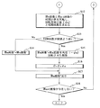
そして、図5に示すように、画像処理装置6の制御回路33は、ステップS1でパラメータであるθ(画像のトータルの回転角度)、n(画像番号)を初期化してθ=0、n=1とする。そしてステップS2で制御回路33はメモリ34に格納されている第n画像データ(この場合は第1画像データ)を読み込み、ステップS3でこのときの回転磁場の磁場の向き(x、y、z)と回転磁場の法線方向(X、Y、Z)とからなる第n磁場データ(この場合は第1磁場データ)をメモリ34から読み込む。
【0023】
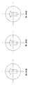
次に、ステップS4で制御回路33は、図9に示すように、第1の補正画像データである第n画像データ’と第2の補正画像データである第n画像データ”とを第n画像データと等しい画像データとする(第n画像データ=第n画像データ’=第n画像データ”:図9は第1画像データ=第1画像データ’=第1画像データ”の場合のイメージを示している)。そして、ステップS5で制御回路33は、画像処理回路32を制御して図10に示すような第n画像データ”に基づく表示画像を表示装置5に表示する。
【0024】
続いて、ステップS6で制御回路33は、nをインクリメントして、ステップS7でメモリ34に格納されている第n画像データ(この場合は第2画像データ)を読み込み、ステップS8でこのときの回転磁場の磁場の向き(x、y、z)と回転磁場の法線方向(X、Y、Z)とからなる第n磁場データ(この場合は第2磁場データ)をメモリ34から読み込む。
【0025】
次に、ステップS9で制御回路33は、第n画像と第n−1画像の回転角度Δθを算出する。詳細には図11に示すように、例として第1画像データの磁場データである第1磁場データの回転磁場の磁場の向きをB1(x1、y1、z1)、回転磁場の法線方向をR1(X1、Y1、Z1)、第2画像データの磁場データである第2磁場データの回転磁場の磁場の向きをB2(x2、y2、z2)、回転磁場の法線方向をR2(X2、Y2、Z2)とする。
【0026】
カプセル内視鏡2の進行方向は刻々と変化するため、単純にB1とB2の角度を回転角とすると、実際の回転角度が合わなくなる可能性がある。そこで、カプセル内視鏡2の進行方向の変化も回転角度に考慮されるように、図11に示すように、R1とB1との法線ベクトルN1とR2とB2との法線ベクトルN2のなす角を回転角度Δθとする。
【0027】
回転角度Δθは、以下で求められる。
【0028】
N1=(y1Z1−Y1z1,z1X1−Z1x1,x1Y1−X1y1)
N2=(y2Z2−Y2z2,z2X2−Z2x2,x2Y2−X2y2)
N1、N2は単位ベクトルであるから、
Δθ1 ・ 2=cos-1{(y1Z1−Y1z1)(y2Z2−Y2z2)
となり、算出される。
【0029】
時間経過と共にΔθ1 ・ 2、Δθ2 ・ 3、、‥‥‥Δθ(n-2) ・ (n-1)、Δθ(n-1) ・ nを順じ求めていくことで回転角を算出することができる。
【0030】
そして、トータルの回転角度θは上記の和をとればよく、θ=ΣΔθ(k-1) ・ kで表されるから、ステップS10で制御回路33は、θ=θ+Δθをトータルの回転角度とする。従って、図12のイメージ図に示すように、例えば第2画像は第1画像を回転角度θ+誤差だけ図の向きに回転させた画像となる。ここで、上記誤差は、カプセル内視鏡2のスクリュー41と体壁との回転の負荷によるカプセル内視鏡2の回転角と回転磁場の回転角との回転角誤差である。
【0031】
そこでまず、ステップS11で制御回路33は、第1の補正画像データである第n画像データ’を第n画像データを角度(−θ)回転させた画像データとする。これにより、図13のイメージ図に示すように、誤差分を考慮しない第1の補正画像である例えば第2画像’を得ることができる。
【0032】
次に、図6のステップS12に移行し、ステップS12で制御回路33は、第n画像データと第n−1画像データの公知の相関計算を実施し、回転角補正量(φn)と相関係数を求め、ステップS13で相関係数が所定の閾値より高いかどうか判断する。この判断により上記図12における誤差を無視するかどうか判定する。
【0033】
相関係数が所定の閾値より高くない場合は、ステップS14で制御回路33は、第2の補正画像データである第n画像データ”を第1の補正画像データである第n画像データ’としてステップS17に進む。相関係数が所定の閾値より高くない場合、すなわち、画像が大きく変化した場合には相関処理結果は採用せず、ステップS11の処理を実施した(第1の補正画像データである第n画像データ’を第n画像データを角度(−θ)回転させた画像データとした)時点で、画像の回転補正は完了する。
【0034】
すなわち、誤差が無視できれば、図14のイメージ図に示すように、ステップS11で第2画像データの回転補正は第2画像データ’(第1の補正画像データ)によって終了し、ステップS14で第2画像データ’(第1の補正画像データ)を第2画像データ”(第2の補正画像データ)とする。
【0035】
相関係数が所定の閾値より高い場合は、ステップS15で制御回路33は、第2の補正画像データである第n画像データ”=第1の補正画像データである第n画像データ’を角度(−φn)回転させた画像データとする。これにより、図15のイメージ図に示すように、第2の補正画像である例えば第2画像”を得ることができる。そして、ステップS16でトータルの回転角度θをθ+φnとしてステップS17に進む。
【0036】
ステップS17では、制御回路33は、画像処理回路32を制御して図16に示すような第n画像データ”に基づく回転補正が完了した表示画像を表示装置5に表示する。そして、ステップS18でメモリ34に第n+1画像データが存在するかどうか判断し存在する場合は図5のステップS6に戻り、存在しない場合は処理を終了する。
【0037】
表示装置5に表示させる画像については、円形の輪郭を持つ画像にすることで、画像の回転処理をユーザに意識させずに表示させることができる。
【0038】
(効果)
このように本実施の形態では、カプセル内視鏡2が撮像した画像の画像データと撮像時の磁場データ(回転磁場の向きと法線方向データ)を関連付けてメモリ34に格納することで、回転磁場によりカプセル内視鏡2を回転させ、向きの変更や進退動作を行わせても、カプセル内視鏡2の回転による画像の回転を第1の補正画像により補正することができる。
【0039】
さらに、カプセル内視鏡2のスクリュー41と体壁との回転の負荷によるカプセル内視鏡2の回転角と回転磁場の回転角との回転角誤差を画像間の相関計算を行うことで第2の補正画像により補正することができる。
【0040】
また、表示装置5に回転を静止させた画像を表示させることができるので、カプセル内視鏡2を画像上で移動させたい方向が容易に認識でき、方向指示装置35を操作することで、制御回路33が方向指示装置35からの指示信号を受け、指示信号に基づく進行制御信号を磁場制御装置4に出力する。これによりカプセル内視鏡2の撮像光学系の軸方向を所望の向きに向けることができる共に、カプセル内視鏡2を撮像光学系の軸上で進退させることが可能となり、ユーザは方向指示装置35を用いることで任意の方向にカプセル内視鏡2を移動させることができる。
【0041】
第2の実施の形態:
図17及び図18は本発明の第2の実施の形態に係わり、図17はカプセル内視鏡システムの外観構成を示す構成図、図18は図17のカプセル内視鏡システムの構成を示すブロック図である。
【0042】
第2の実施の形態は、第1の実施の形態とほとんど同じであるので、異なる点のみ説明し、同一の構成には同じ符号をつけ説明は省略する。
【0043】
(構成・作用)
図17に示すように、本実施の形態のカプセル内視鏡システム1aは、体腔内に挿入され外部回転磁場により自走して体腔内の画像を撮像するカプセル内視鏡2と、前記外部回転磁場を発生する回転磁場発生装置3と、回転磁場発生装置3が発生する回転磁場を制御する磁場制御装置4と、磁場制御装置4からの磁場制御信号を受信すると共にカプセル内視鏡2からの画像を無線にて受信し画像データと磁場データを格納する体外ユニット51とを備えて構成され、この体外ユニット51は格納された画像データと磁場データをパーソナルコンピュータ等で構成される画像処理装置52に出力することができるようになっている。
【0044】
体外ユニット51から画像処理装置52へのデータの受け渡しは、カプセル内視鏡2の検査終了後に、例えば体外ユニット51と画像処理装置52とを通信ケーブルで直接接続したり、着脱自在な情報記録媒体(例えばFDD,MO,CD−R,CD−R/W,DVD−R等)を介したり、さらには院内LAN等の通信回線を用いて行うことができ、画像処理装置52は画像データと磁場データとを用いて第1の実施の形態と同様に画像の回転を静止させた後画像処理して表示装置5に表示する。
【0045】
図18に示すように、体外ユニット51は、無線回路31と、メモリ34と、制御回路33とを備え、メモリ34は制御回路33により磁場データを画像データと関連付けて格納するようになっている。
【0046】
画像処理装置52は、画像データと磁場データとを用いて第1の実施の形態と同様に画像の回転を静止させた後画像処理して表示装置5に表示する画像処理回路53を備えて構成される。
【0047】
その他の構成・作用は第1の実施の形態と同じである。
【0048】
(効果)
このように本実施の形態では、第1の実施の形態と同等に、回転磁場によりカプセル内視鏡2を回転させ、向きの変更や進退動作を行わせても、カプセル内視鏡2の回転による画像の回転を第1の補正画像により補正することができ、また、カプセル内視鏡2のスクリュー41と体壁との回転の負荷によるカプセル内視鏡2の回転角と回転磁場の回転角との回転角誤差を画像間の相関計算を行うことで第2の補正画像により補正することができる。
【0049】
さらに本実施の形態では、カプセル内視鏡2の検査時は、磁場データと画像データとを関連付けてメモリ34に格納するだけであって、回転補正処理は検査後に行うので、検査を効率的に行うことができる。また、画像処理装置52を汎用のパーソナルコンピュータにより構成できるので、カプセル内視鏡システム1aを安価に構成することが可能となる。
【0050】
第3の実施の形態:
図19ないし図22は本発明の第3の実施の形態に係わり、図19はカプセル内視鏡システムの構成を示すブロック図、図20は図19のカプセル内視鏡の動作の一例を示す図、図21は図19のカプセル内視鏡システムによるジグリング処理の流れを示す図、図22は図21の処理の作用を説明する図である。
【0051】
第3の実施の形態は、第1の実施の形態とほとんど同じであるので、異なる点のみ説明し、同一の構成には同じ符号をつけ説明は省略する。
【0052】
(構成)
図19に示すように、本実施の形態の画像処理装置6の画像処理回路32aは、回転を静止させた画像データより管腔方向を検出する管腔方向検出部61を備えている。この管腔方向検出部61により第1の実施の形態で用いられた方向指示装置35を使用することなく自動的に管腔方向を検出して進行し観察画像を撮像することができる。
【0053】
管腔方向検出部61は、視野内に存在する明瞭な管腔から、直進方向に進行を継続するものと判断し、視野内に管腔は存在しない場合は何らかの情報に基づき進行方向、すなわち管腔の存在する方向を判断することとなる。
【0054】
視野内に管腔が存在しない場合の進行方向の判断要素の一つとして、画像中の明暗変化方向があげられる。例えばカプセル内視鏡先端に近い位置から遠くなる位置にかけて大域的な明暗の変化が生じているとする。進行方向はカプセル内視鏡先端から遠い方向となることより、画像中の明部から暗部への変化方向の検知に基づき、挿入方向を検出することが可能となる。
【0055】
管腔方向検出部61の詳細な構成・作用は、例えば本出願人が先に出願した特願2001−292230号に記載されている挿入方向検出装置と同じであるので説明は省略する。
【0056】
その他の構成は第1の実施の形態と同じである。
【0057】
(作用)
第1の実施の形態と同様に画像の回転を静止させ、表示装置5に表示させると共に、回転を静止させた画像を元に、管腔方向検出部61がカプセル内視鏡2の進行方向を検出して指示信号を画像処理装置6の制御回路33に出力する。制御回路33は第1の実施の形態と同等に指示信号を受け磁場制御装置4を制御しカプセル内視鏡2を管腔進行方向に移動させる。
【0058】
また、図20に示すように、例えば管腔が腸管71のように細径で鋭角に曲がってカプセル内視鏡2が向きが変えられず進行できない場合には、本実施の形態では以下に示す処理によりカプセル内視鏡2をジグリングさせる。
【0059】
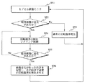
すなわち、図21に示すように、制御回路33は、ステップS51で回転を止めた画像をモニタし、ステップS52で画像の相関を計算し画像に変化があるかとどうか判断し、ある場合にはステップS53で通常の回転磁場を発生させてステップS51に戻り、画像に変化がない場合はカプセル内視鏡2が進行できない状態と判断して、ステップS54に進む。
【0060】
ステップS54では、制御回路33は、.図22に示すように、回転磁場の軸をジグリング制御する。具体的には、例えば(1)回転磁場の軸をコーン状に動かす、(2)回転磁場の軸を単に左右に振る、(3)回転磁場の軸を単に短振幅で振動させる、(4)回転磁場の軸を単に90度変える等を実施する。この回転磁場の軸をジグリング制御によりカプセル内視鏡2をつっかかった状態からの脱却を試みる。
【0061】
そして、ステップS55で制御回路33は、画像の相関を計算し画像に変化があるかとどうか判断し、画像に変化がない場合はステップS54に戻り、画像に変化ある場合にはステップS56で画像変化があった向きを記憶し、その向きで通常の回転磁場を発生させステップS51に戻る。
【0062】
(効果)
このように本実施の形態では、第1の実施の形態の効果に加え、カプセル内視鏡2の進行方向をシステムが判断し制御できるので、ユーザが進行方向を操作する必要がなく観察に集中できる。また、ジグリング制御を行うので、狭い管腔内の通過性を効果的に改善することが可能である。
【0063】
第4の実施の形態:
図23ないし図26は本発明の第4の実施の形態に係わり、図23はカプセル内視鏡システムの構成を示すブロック図、図24は図23のX軸磁場発生装置の構成を示すブロック図、図25は図23のカプセル内視鏡システムの作用を説明する第1の図、図26は図23のカプセル内視鏡システムの作用を説明する第2の図である。
【0064】
第4の実施の形態は、第1の実施の形態とほとんど同じであるので、異なる点のみ説明し、同一の構成には同じ符号をつけ説明は省略する。
【0065】
(構成)
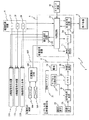
図23に示すように、本実施の形態では、複数の対コイルからなるX軸磁場発生装置101と、複数の対コイル群からなるY軸磁場発生装置102と、複数の対コイルからなるZ軸磁場発生装置103とから回転磁場発生装置を構成している。また、本実施の形態のカプセル内視鏡システムは、固定マグネット21の磁場の強度と向きとを検出する2組の3軸センスコイル104,105と、該3軸等方センスコイル104,105の検知信号よりカプセル内視鏡2の3次元位置と向きを算出する位置検出回路106とからなる位置検出装置107を有しており、位置検出回路106は算出したカプセル内視鏡2の3次元位置データと向きデータを画像処理装置6の制御回路33に出力するようになっている。
【0066】
また、画像処理装置6は、制御回路33の制御によりX軸磁場発生装置101、Y軸磁場発生装置102、Z軸磁場発生装置103に選択制御信号を出力する磁石選択回路110を備えて構成される。
【0067】
X軸磁場発生装置101は、図24に示すように、マトリックス状に配置された複数、例えば16個のコイル(1,1)A〜(4,4)Aからなる第1のコイル群Aと、マトリックス状に配置された複数、例えば16個のコイル(1,1)B〜(4,4)Bからなる第2のコイル群111Bとを有し、第1のコイル群111Aと第2のコイル群111Bとが対向し対向電磁石(回転磁場発生用ヘルムホルツコイル)を形成している。
【0068】
また、第1のコイル群Aのコイル(i,j)Aを選択的に駆動する駆動手段であるijA−AMPを備え(i=1〜4;整数,j=1〜4;整数)、コイル(i,j)Aと対となって駆動される第2のコイル群Bのコイル(i,j)Bを選択的に駆動する駆動手段であるijB−AMPを備えている(i=1〜4;整数,j=1〜4;整数)。
【0069】
ijA−AMPとijB−AMP(i=1〜4;整数,j=1〜4;整数)は、コイル選択回路112により選択・制御される。詳細には、このコイル選択回路112は、画像処理装置6の磁石選択回路110からの選択制御信号及び磁場制御装置4の駆動アンプ14〜16からの磁場制御信号に基づきijA−AMPとijB−AMP(i=1〜4;整数,j=1〜4;整数)を選択・制御する。
【0070】
Y軸磁場発生装置102、Z軸磁場発生装置103はX軸磁場発生装置101と同じ構成であるので説明は省略する。その他の構成は第1の実施の形態と同じである。
【0071】
(作用)
位置検出装置107は、カプセル内視鏡2に内蔵されている固定マグネット21から発生する磁場の強度と向きを2組の3軸センスコイル104,105で検知し、位置検出回路106でカプセル内視鏡2の3次元位置と向きを算出して、3次元位置データと向きデータを画像処理装置6の制御回路33に出力する。
【0072】
制御回路33は3次元位置データにより駆動するコイル(i,j)Aとコイル(i,j)B(i=1〜4;整数,j=1〜4;整数)を選択するための選択信号を磁石選択回路110に出力することで、磁石選択回路110がコイル選択回路112に選択制御信号を出力し、コイル(i,j)Aとコイル(i,j)B(i=1〜4;整数,j=1〜4;整数)が選択される。
【0073】
駆動されるコイル(i,j)Aとコイル(i,j)B(i=1〜4;整数,j=1〜4;整数)は、例えば図25のように、カプセル内視鏡2の位置に従い、カプセル内視鏡2の運動に有効な回転磁場が印加されるように選択される。
【0074】
ユーザが回転が静止した画像を表示装置5で観察しながら方向指示装置35を操作し運動方向を指示すると、画像処理装置6の制御回路33は磁場制御装置4に進行制御信号を出力する。磁場制御装置4は、駆動されているコイル(i,j)Aとコイル(i,j)B(i=1〜4;整数,j=1〜4;整数)により発生している回転磁場の回転方向(法線方向)を変更させる磁場制御信号をコイル選択回路112に出力する。
【0075】
これによりカプセル内視鏡2が運動し移動することで、カプセル内視鏡2の3次元位置が再び位置検出装置107により検出され、3次元位置データに基づき画像処理装置6の制御回路33が磁石選択回路110を介してコイル選択回路112を制御してカプセル内視鏡2の運動に有効な回転磁場が印加されるように駆動されるコイル(i,j)Aとコイル(i,j)B(i=1〜4;整数,j=1〜4;整数)が連続的に選択され直す。
【0076】
具体的には、例えば図25に示した位置にあったカプセル内視鏡2が方向指示装置35の操作により選択されているコイルの回転磁場が回転し、図26に示すような位置にカプセル内視鏡2が位置すると、この3次元位置で有効な回転磁場が印加されるように駆動されるコイルが選択し直される。
【0077】
その他の作用は第1の実施の形態と同じである。
【0078】
(効果)
このように本実施の形態では、第1の実施の形態の効果に加え、人体全体でなく部分部分に回転磁場を印加することができるので、カプセル内視鏡2に対して一様な回転磁場を与えることができると共に、低消費電力で駆動することができる。また、コイル1つ1つの大きさを小さくできるので軽量で安価に構成することができる。
【0079】
[付記]
(付記項1) 前記磁場変向手段は、前記カプセル型内視鏡本体の進行方向を指示する入力手段を有する
ことを特徴とする請求項1に記載のカプセル内視鏡システム。
【0080】
(付記項2) 回転磁場を発生する磁場発生手段と、
前記磁場発生手段が発生した前記回転磁場を受け、回転して推力を得るカプセル型内視鏡本体と、
前記カプセル型内視鏡本体を目的の進行方向に向けるべく前記磁場発生手段による前記回転磁場の向きを変更する磁場変向手段と、
前記カプセル型医療装置本体に設けられた撮像システムと、
前記撮像システムからの画像データに基づき、前記カプセル型内視鏡本体の進行方向を算出する進行方向算出手段と、
前記進行方向算出手段の算出結果に基づき前記磁場変向手段を制御する制御手段と
を備えたことを特徴とするカプセル内視鏡システム。
【0082】
(付記項4) 前記カプセル型内視鏡本体の位置を検出する位置検出手段を有し、
前記制御手段は、前記進行方向算出手段の算出結果及び前記位置検出手段が検出した前記カプセル型内視鏡本体の位置に基づき前記磁場変向手段を制御する
ことを特徴とする付記項2に記載のカプセル内視鏡システム。
【0083】
(付記項5) 前記画像処理手段で生成される表示画像が円形の輪郭を持つ
ことを特徴とする付記項1ないし4のいずれか1つに記載のカプセル内視鏡システム。
【0084】
本発明は、上述した実施の形態に限定されるものではなく、本発明の要旨を変えない範囲において、種々の変更、改変等が可能である。
【0085】
【発明の効果】
以上説明したように本発明によれば、カプセル内視鏡本体に推進力を与えた場合にも、画像の回転を静止させることができるという効果がある。
【図面の簡単な説明】
【図1】本発明の第1の実施の形態に係るカプセル内視鏡システムの外観構成を示す構成図
【図2】図1のカプセル内視鏡システムの構成を示すブロック図
【図3】図2のカプセル内視鏡の外観構成を示す構成図
【図4】図3のカプセル内視鏡の作用を説明する図
【図5】図2のカプセル内視鏡システムの処理を説明する第1のフローチャート
【図6】図2のカプセル内視鏡システムの処理を説明する第2のフローチャート
【図7】図5及び図6の作用を説明する第1の図
【図8】図5及び図6の作用を説明する第2の図
【図9】図5及び図6の作用を説明する第3の図
【図10】図5及び図6の作用を説明する第4の図
【図11】図5及び図6の作用を説明する第5の図
【図12】図5及び図6の作用を説明する第6の図
【図13】図5及び図6の作用を説明する第7の図
【図14】図5及び図6の作用を説明する第8の図
【図15】図5及び図6の作用を説明する第9の図
【図16】図5及び図6の作用を説明する第10の図
【図17】本発明の第2の実施の形態に係るカプセル内視鏡システムの外観構成を示す構成図
【図18】図17のカプセル内視鏡システムの構成を示すブロック図
【図19】本発明の第3の実施の形態に係るカプセル内視鏡システムの構成を示すブロック図
【図20】図19のカプセル内視鏡の動作の一例を示す図
【図21】図19のカプセル内視鏡システムによるジグリング処理の流れを示す図
【図22】図21の処理の作用を説明する図
【図23】本発明の第4の実施の形態に係るカプセル内視鏡システムの構成を示すブロック図
【図24】図23のX軸磁場発生装置の構成を示すブロック図
【図25】図23のカプセル内視鏡システムの作用を説明する第1の図
【図26】図23のカプセル内視鏡システムの作用を説明する第2の図
【符号の説明】
1…カプセル内視鏡システム
2…カプセル内視鏡
2a…カプセル本体
3…回転磁場発生装置
4…磁場制御装置
5…表示装置
6…画像処理装置
11…第1の電磁石
12…第2の電磁石
13…第3の電磁石
14〜16…駆動アンプ
17〜19…制御信号発生器
21…固定マグネット
22…照明素子
23…撮像素子
24…信号処理回路
25、34…メモリ
26、31…無線回路
32…画像処理回路
33…制御回路
35…方向指示装置
41…スクリュー
42…対物光学系[0001]
BACKGROUND OF THE INVENTION
The present invention relates to a capsule endoscope system that drives and controls a capsule endoscope that self-travels in a lumen and images an observation site.
[0002]
[Prior art]
For example, in Japanese Patent Laid-Open No. 2001-179700, “a magnetic field generating unit that generates a rotating magnetic field, a robot body that receives the rotating magnetic field generated by the magnetic field generating unit and rotates to obtain thrust, and a position of the robot main body are detected. And a magnetic field changing means for changing the direction of the rotating magnetic field generated by the magnetic field generating unit to direct the robot main body in a direction to reach the destination based on the position of the robot main body detected by the position detecting unit. A movement control system for a movable micromachine characterized by comprising:
[0003]
[Problems to be solved by the invention]
However, for example, when an image sensor is provided in such a robot body to form a capsule endoscope and image observation is performed, the observation image also rotates with the rotation of the capsule body of the capsule endoscope. There is a problem that it is difficult to check the image and it makes you feel uncomfortable.
[0004]
The present invention has been made in view of the above circumstances, and an object of the present invention is to provide a capsule endoscope system capable of stopping the rotation of an image even when a propelling force is applied to the capsule endoscope body. It is said.
[0005]
[Means for Solving the Problems]
The capsule endoscope system according to
[0006]
DETAILED DESCRIPTION OF THE INVENTION
Embodiments of the present invention will be described below with reference to the drawings.
[0007]
First embodiment:
FIGS. 1 to 16 relate to the first embodiment of the present invention, FIG. 1 is a block diagram showing the external configuration of the capsule endoscope system, and FIG. 2 is a block diagram showing the configuration of the capsule endoscope system of FIG. FIG. 3, FIG. 3 is a block diagram showing an external configuration of the capsule endoscope of FIG. 2, FIG. 4 is a diagram for explaining the operation of the capsule endoscope of FIG. 3, and FIG. 5 is a process of the capsule endoscope system of FIG. FIG. 6 is a second flowchart for explaining the processing of the capsule endoscope system of FIG. 2, FIG. 7 is a first diagram for explaining the operation of FIGS. 5 and 6, and FIG. FIG. 9 is a third diagram illustrating the operation of FIGS. 5 and 6, and FIG. 10 is a fourth diagram illustrating the operation of FIGS. 5 and 6. FIG. 11 is a fifth diagram illustrating the operation of FIGS. 5 and 6, and FIG. 12 is a sixth diagram illustrating the operation of FIGS. 5 and 6. FIG. 13, FIG. 13 is a seventh diagram illustrating the operation of FIGS. 5 and 6, FIG. 14 is an eighth diagram illustrating the operation of FIGS. 5 and 6, and FIG. 15 is a diagram illustrating the operation of FIGS. FIG. 16 is a tenth diagram for explaining the operation of FIG. 5 and FIG.
[0008]
As shown in FIG. 1, a
[0009]
As shown in FIG. 2, the rotating
[0010]
In the
[0011]
The
[0012]
In addition, the
[0013]
In this
[0014]
As shown in FIG. 3, the
[0015]
The direction of the dipole of the
[0016]
In addition, although the direction of the magnetic pole of the
[0017]
As shown in FIG. 4, even if the
[0018]
The user can change the normal direction of the rotating magnetic field to the desired direction as described above by monitoring the endoscopic image of the display device 5 and instructing the desired direction with the
[0019]
(Function)
The operation of this embodiment configured as described above will be described with reference to the flowcharts of FIGS. 5 and 6 and the explanatory diagrams of FIGS.
[0020]
When the orientation of the
[0021]
First, when the
[0022]
Then, as shown in FIG. 5, the
[0023]
Next, in step S4, as shown in FIG. 9, the
[0024]
Subsequently, in step S6, the
[0025]
Next, in step S9, the
[0026]
Since the traveling direction of the
[0027]
The rotation angle Δθ is obtained as follows.
[0028]
N1= (Y1Z1-Y1z1, Z1X1-Z1x1, X1Y1-X1y1)
N2= (Y2Z2-Y2z2, Z2X2-Z2x2, X2Y2-X2y2)
N1, N2Is a unit vector, so
Δθ1 ・ 2= Cos-1{(Y1Z1-Y1z1) (Y2Z2-Y2z2)
And calculated.
[0029]
Δθ over time1 ・ 2, Δθ2 ・ Three, ............ Δθ(n-2) ・ (n-1), Δθ(n-1) ・ nThe rotation angle can be calculated by sequentially obtaining.
[0030]
The total rotation angle θ should be the sum of the above, θ = ΣΔθ(k-1) ・ kTherefore, in step S10, the
[0031]
Therefore, first, in step S11, the
[0032]
Next, the process proceeds to step S12 in FIG. 6. In step S12, the
[0033]
If the correlation coefficient is not higher than the predetermined threshold, in step S14, the
[0034]
That is, if the error can be ignored, as shown in the image diagram of FIG. 14, the rotation correction of the second image data is completed with the second image data ′ (first corrected image data) in step S11, and the second image data is ended in step S14. Data ′ (first corrected image data) is defined as second image data ”(second corrected image data).
[0035]
When the correlation coefficient is higher than the predetermined threshold value, in step S15, the
[0036]
In step S17, the
[0037]
The image displayed on the display device 5 can be displayed without making the user aware of the image rotation process by making the image have a circular outline.
[0038]
(effect)
As described above, in the present embodiment, the image data of the image captured by the
[0039]
Further, the second calculation is performed by calculating the correlation between the rotation angle errors between the rotation angle of the
[0040]
In addition, since the display device 5 can display an image whose rotation is stationary, the direction in which the
[0041]
Second embodiment:
FIGS. 17 and 18 relate to the second embodiment of the present invention, FIG. 17 is a configuration diagram showing an external configuration of the capsule endoscope system, and FIG. 18 is a block diagram showing a configuration of the capsule endoscope system of FIG. FIG.
[0042]
Since the second embodiment is almost the same as the first embodiment, only different points will be described, and the same components are denoted by the same reference numerals and description thereof will be omitted.
[0043]
(Configuration and action)
As shown in FIG. 17, the capsule endoscope system 1a of the present embodiment includes a
[0044]
Data is transferred from the
[0045]
As shown in FIG. 18, the
[0046]
The
[0047]
Other configurations and operations are the same as those in the first embodiment.
[0048]
(effect)
As described above, in the present embodiment, as in the first embodiment, the
[0049]
Furthermore, in the present embodiment, when the
[0050]
Third embodiment:
FIGS. 19 to 22 relate to the third embodiment of the present invention, FIG. 19 is a block diagram showing the configuration of the capsule endoscope system, and FIG. 20 is a diagram showing an example of the operation of the capsule endoscope of FIG. FIG. 21 is a diagram showing the flow of the jigging process by the capsule endoscope system of FIG. 19, and FIG. 22 is a diagram for explaining the operation of the process of FIG.
[0051]
Since the third embodiment is almost the same as the first embodiment, only different points will be described, and the same components are denoted by the same reference numerals and description thereof will be omitted.
[0052]
(Constitution)
As shown in FIG. 19, the image processing circuit 32a of the
[0053]
The lumen
[0054]
One of the factors for determining the direction of travel when no lumen is present in the field of view is the direction of change in brightness in the image. For example, it is assumed that a change in global brightness occurs from a position close to the distal end of the capsule endoscope to a position far from the capsule endoscope. Since the advancing direction is a direction far from the distal end of the capsule endoscope, it is possible to detect the insertion direction based on detection of the change direction from the bright part to the dark part in the image.
[0055]
The detailed configuration and operation of the lumen
[0056]
Other configurations are the same as those of the first embodiment.
[0057]
(Function)
As in the first embodiment, the rotation of the image is stopped and displayed on the display device 5, and the lumen
[0058]
In addition, as shown in FIG. 20, for example, when the lumen is thin and bent at an acute angle such as the
[0059]
That is, as shown in FIG. 21, the
[0060]
In step S54, the
[0061]
In step S55, the
[0062]
(effect)
Thus, in this embodiment, in addition to the effects of the first embodiment, the system can determine and control the traveling direction of the
[0063]
Fourth embodiment:
FIG. 23 to FIG. 26 relate to the fourth embodiment of the present invention, FIG. 23 is a block diagram showing the configuration of the capsule endoscope system, and FIG. 24 is a block diagram showing the configuration of the X-axis magnetic field generator of FIG. 25 is a first diagram for explaining the operation of the capsule endoscope system of FIG. 23, and FIG. 26 is a second diagram for explaining the operation of the capsule endoscope system of FIG.
[0064]
Since the fourth embodiment is almost the same as the first embodiment, only different points will be described, and the same components are denoted by the same reference numerals and description thereof will be omitted.
[0065]
(Constitution)
As shown in FIG. 23, in the present embodiment, an X-axis
[0066]
Further, the
[0067]
As shown in FIG. 24, the X-axis
[0068]
Further, ijA-AMP which is a driving means for selectively driving the coil (i, j) A of the first coil group A is provided (i = 1 to 4; integer, j = 1 to 4; integer). (I, j) ijB-AMP, i.e., driving means for selectively driving the coil (i, j) B of the second coil group B driven in pairs with A (i = 1 to 1) is provided. 4; integer, j = 1 to 4; integer).
[0069]
ijA-AMP and ijB-AMP (i = 1 to 4; integer, j = 1 to 4; integer) are selected and controlled by the
[0070]
Since the Y-axis
[0071]
(Function)
The
[0072]
The
[0073]
Coil (i, j) A and coil (i, j) B (i = 1 to 4; integer, j = 1 to 4; integer) to be driven are, for example, as shown in FIG. According to the position, it is selected so that a rotating magnetic field effective for the movement of the
[0074]
When the user operates the
[0075]
As a result, the
[0076]
Specifically, for example, the
[0077]
Other operations are the same as those in the first embodiment.
[0078]
(effect)
As described above, in the present embodiment, in addition to the effects of the first embodiment, a rotating magnetic field can be applied to a partial portion rather than the entire human body, so that a uniform rotating magnetic field is applied to the
[0079]
[Appendix]
(Additional Item 1) The magnetic field redirecting means has input means for instructing the traveling direction of the capsule endoscope body.
The capsule endoscope system according to
[0080]
(Additional Item 2) Magnetic field generating means for generating a rotating magnetic field;
A capsule endoscope body that receives the rotating magnetic field generated by the magnetic field generating means and obtains a thrust by rotating;
Magnetic field redirecting means for changing the direction of the rotating magnetic field by the magnetic field generating means so as to direct the capsule endoscope body in a desired traveling direction;
An imaging system provided in the capsule medical device body;
Based on image data from the imaging system, a traveling direction calculation means for calculating a traveling direction of the capsule endoscope body,
Control means for controlling the magnetic field redirecting means based on the calculation result of the traveling direction calculating means;
A capsule endoscope system comprising:
[0082]
(Additional Item 4) It has a position detection means for detecting the position of the capsule endoscope body,
The control means controls the magnetic field direction changing means based on the calculation result of the traveling direction calculation means and the position of the capsule endoscope body detected by the position detection means.
[0083]
(Additional Item 5) The display image generated by the image processing means has a circular outline.
The capsule endoscope system according to any one of
[0084]
The present invention is not limited to the above-described embodiments, and various changes and modifications can be made without departing from the scope of the present invention.
[0085]
【The invention's effect】
As described above, according to the present invention, there is an effect that the rotation of the image can be stopped even when a propulsive force is applied to the capsule endoscope body.
[Brief description of the drawings]
FIG. 1 is a configuration diagram showing an external configuration of a capsule endoscope system according to a first embodiment of the present invention.
2 is a block diagram showing a configuration of the capsule endoscope system of FIG. 1;
3 is a configuration diagram showing an external configuration of the capsule endoscope of FIG. 2;
4 is a diagram for explaining the operation of the capsule endoscope of FIG. 3;
FIG. 5 is a first flowchart for explaining processing of the capsule endoscope system of FIG. 2;
6 is a second flowchart for explaining processing of the capsule endoscope system of FIG. 2; FIG.
7 is a first diagram illustrating the operation of FIGS. 5 and 6. FIG.
FIG. 8 is a second diagram for explaining the operation of FIGS. 5 and 6;
9 is a third diagram for explaining the operation of FIGS. 5 and 6. FIG.
10 is a fourth diagram for explaining the operation of FIGS. 5 and 6. FIG.
11 is a fifth diagram for explaining the operation of FIGS. 5 and 6. FIG.
12 is a sixth diagram illustrating the operation of FIGS. 5 and 6; FIG.
13 is a seventh diagram for explaining the operation of FIGS. 5 and 6; FIG.
14 is an eighth diagram for explaining the operation of FIGS. 5 and 6; FIG.
15 is a ninth diagram for explaining the operation of FIGS. 5 and 6; FIG.
FIG. 16 is a tenth diagram for explaining the operation of FIGS. 5 and 6;
FIG. 17 is a configuration diagram showing an external configuration of a capsule endoscope system according to a second embodiment of the present invention.
18 is a block diagram showing the configuration of the capsule endoscope system of FIG.
FIG. 19 is a block diagram showing a configuration of a capsule endoscope system according to a third embodiment of the present invention.
20 is a diagram showing an example of the operation of the capsule endoscope of FIG.
FIG. 21 is a diagram showing a flow of jigging processing by the capsule endoscope system of FIG.
FIG. 22 is a diagram for explaining the operation of the process of FIG.
FIG. 23 is a block diagram showing a configuration of a capsule endoscope system according to a fourth embodiment of the present invention.
24 is a block diagram showing the configuration of the X-axis magnetic field generator of FIG.
FIG. 25 is a first diagram illustrating the operation of the capsule endoscope system of FIG. 23;
26 is a second diagram for explaining the operation of the capsule endoscope system of FIG. 23. FIG.
[Explanation of symbols]
1 ... Capsule endoscope system
2 ... capsule endoscope
2a ... Capsule body
3 ... Rotating magnetic field generator
4 ... Magnetic field control device
5. Display device
6. Image processing apparatus
11 ... 1st electromagnet
12 ... Second electromagnet
13 ... Third electromagnet
14-16 ... Drive amplifier
17-19: Control signal generator
21 ... Fixed magnet
22 ... Lighting element
23. Imaging element
24. Signal processing circuit
25, 34 ... Memory
26, 31 ... wireless circuit
32. Image processing circuit
33. Control circuit
35 ... Direction indicating device
41 ... Screw
42 ... Objective optical system
Claims (11)
前記磁場発生手段が発生した前記回転磁場を受け、回転して推力を得るカプセル型内視鏡本体と、
前記カプセル型内視鏡本体を目的の進行方向に向けるべく前記磁場発生手段による前記回転磁場の向きを変更する磁場変向手段と、
前記カプセル型内視鏡本体に設けられた撮像システムと、
前記撮像システムからの画像データを入力し、前記回転磁場の向きに基づき前記画像データの回転処理を行う画像処理手段と、
を備えたことを特徴とするカプセル内視鏡システム。A magnetic field generating means for generating a rotating magnetic field;
A capsule endoscope body that receives the rotating magnetic field generated by the magnetic field generating means and obtains a thrust by rotating;
Magnetic field redirecting means for changing the direction of the rotating magnetic field by the magnetic field generating means so as to direct the capsule endoscope body in a desired traveling direction;
An imaging system provided in the capsule endoscope body;
Image processing means for inputting image data from the imaging system and performing rotation processing of the image data based on the direction of the rotating magnetic field;
A capsule endoscope system comprising:
Priority Applications (8)
| Application Number | Priority Date | Filing Date | Title |
|---|---|---|---|
| JP2002105493A JP3917885B2 (en) | 2002-04-08 | 2002-04-08 | Capsule endoscope system |
| US10/409,329 US7122001B2 (en) | 2002-04-08 | 2003-04-08 | Encapsulated endoscope system in which endoscope moves in lumen by itself and rotation of image of region to be observed is ceased |
| US11/496,560 US7905827B2 (en) | 2002-04-08 | 2006-07-31 | Encapsulated endoscope system in which endoscope moves in lumen by itself and rotation of image of region to be observed is ceased |
| US11/786,790 US8033989B2 (en) | 2002-04-08 | 2007-04-12 | Encapsulated endoscope system in which endoscope moves in lumen by itself and rotation of image of region to be observed is ceased |
| US11/786,798 US20070197870A1 (en) | 2002-04-08 | 2007-04-12 | Encapsulated endoscope system in which endoscope moves in lumen by itself and rotation of image of region to be observed is ceased |
| US11/786,738 US8062210B2 (en) | 2002-04-08 | 2007-04-12 | Encapsulated endoscope system in which endoscope moves in lumen by itself and rotation of image of region to be observed is ceased |
| US13/223,874 US8419629B2 (en) | 2002-04-08 | 2011-09-01 | Encapsulated endoscope system in which endoscope moves in lumen by itself and rotation of image of region to be observed is ceased |
| US13/845,700 US8753265B2 (en) | 2002-04-08 | 2013-03-18 | Encapsulated endoscope system in which endoscope moves in lumen by itself and rotation of image of region to be observed is ceased |
Applications Claiming Priority (1)
| Application Number | Priority Date | Filing Date | Title |
|---|---|---|---|
| JP2002105493A JP3917885B2 (en) | 2002-04-08 | 2002-04-08 | Capsule endoscope system |
Related Child Applications (1)
| Application Number | Title | Priority Date | Filing Date |
|---|---|---|---|
| JP2005095718A Division JP4246171B2 (en) | 2005-03-29 | 2005-03-29 | Capsule endoscope system and magnetic field generator |
Publications (3)
| Publication Number | Publication Date |
|---|---|
| JP2003299612A JP2003299612A (en) | 2003-10-21 |
| JP2003299612A5 JP2003299612A5 (en) | 2005-09-15 |
| JP3917885B2 true JP3917885B2 (en) | 2007-05-23 |
Family
ID=29390173
Family Applications (1)
| Application Number | Title | Priority Date | Filing Date |
|---|---|---|---|
| JP2002105493A Expired - Fee Related JP3917885B2 (en) | 2002-04-08 | 2002-04-08 | Capsule endoscope system |
Country Status (2)
| Country | Link |
|---|---|
| US (7) | US7122001B2 (en) |
| JP (1) | JP3917885B2 (en) |
Families Citing this family (161)
| Publication number | Priority date | Publication date | Assignee | Title |
|---|---|---|---|---|
| US6379334B1 (en) | 1997-02-10 | 2002-04-30 | Essex Technology, Inc. | Rotate advance catheterization system |
| US7048717B1 (en) | 1999-09-27 | 2006-05-23 | Essex Technology, Inc. | Rotate-to-advance catheterization system |
| IL159616A0 (en) | 2001-06-28 | 2004-06-01 | Given Imaging Ltd | In vivo imaging device with a small cross sectional area |
| US9113846B2 (en) * | 2001-07-26 | 2015-08-25 | Given Imaging Ltd. | In-vivo imaging device providing data compression |
| US20050187433A1 (en) * | 2001-07-26 | 2005-08-25 | Given Imaging Ltd. | In-vivo imaging device providing constant bit rate transmission |
| US8428685B2 (en) * | 2001-09-05 | 2013-04-23 | Given Imaging Ltd. | System and method for magnetically maneuvering an in vivo device |
| JP3917885B2 (en) | 2002-04-08 | 2007-05-23 | オリンパス株式会社 | Capsule endoscope system |
| US20030216622A1 (en) * | 2002-04-25 | 2003-11-20 | Gavriel Meron | Device and method for orienting a device in vivo |
| WO2004036803A2 (en) | 2002-10-15 | 2004-04-29 | Given Imaging Ltd. | Device, system and method for transfer of signals to a moving device |
| WO2004058041A2 (en) | 2002-12-26 | 2004-07-15 | Given Imaging Ltd. | Immobilizable in vivo sensing device |
| JP4503930B2 (en) * | 2003-01-30 | 2010-07-14 | オリンパス株式会社 | Medical equipment |
| CN1747679B (en) * | 2003-02-04 | 2012-10-03 | 奥林巴斯株式会社 | Medical apparatus guiding system and control method thereof |
| IL155175A (en) * | 2003-03-31 | 2012-01-31 | Given Imaging Ltd | Diagnostic device using data compression |
| US20070043263A1 (en) * | 2003-04-03 | 2007-02-22 | Wakefield Glenn M | Simultaneous magnetic control of multiple objects |
| IL162740A (en) | 2003-06-26 | 2010-06-16 | Given Imaging Ltd | Device, method and system for reduced transmission imaging |
| US7960935B2 (en) | 2003-07-08 | 2011-06-14 | The Board Of Regents Of The University Of Nebraska | Robotic devices with agent delivery components and related methods |
| EP1690490B1 (en) | 2003-11-11 | 2012-04-18 | Olympus Corporation | Capsule type medical device system |
| US20050123179A1 (en) * | 2003-12-05 | 2005-06-09 | Eastman Kodak Company | Method and system for automatic axial rotation correction in vivo images |
| JP4489023B2 (en) * | 2003-12-22 | 2010-06-23 | 旭化成エレクトロニクス株式会社 | Azimuth measuring device |
| JP4150663B2 (en) * | 2003-12-25 | 2008-09-17 | オリンパス株式会社 | In-subject position detection system |
| JP4373204B2 (en) * | 2003-12-26 | 2009-11-25 | オリンパス株式会社 | In-subject position detection system |
| US7625338B2 (en) * | 2003-12-31 | 2009-12-01 | Given Imaging, Ltd. | In-vivo sensing device with alterable fields of view |
| US8702597B2 (en) * | 2003-12-31 | 2014-04-22 | Given Imaging Ltd. | Immobilizable in-vivo imager with moveable focusing mechanism |
| US8206285B2 (en) * | 2003-12-31 | 2012-06-26 | Given Imaging Ltd. | Apparatus, system and method to indicate in-vivo device location |
| JP4455067B2 (en) * | 2004-01-14 | 2010-04-21 | オリンパス株式会社 | Capsule endoscope device |
| US7751866B2 (en) | 2004-03-08 | 2010-07-06 | Olympus Corporation | Detecting system of position and posture of capsule medical device |
| JP4547181B2 (en) * | 2004-04-01 | 2010-09-22 | オリンパス株式会社 | In-subject position detection system |
| EP1731093B1 (en) * | 2004-03-29 | 2013-01-09 | Olympus Corporation | System for detecting position in examinee |
| JP4520198B2 (en) * | 2004-04-07 | 2010-08-04 | オリンパス株式会社 | In-subject position display system |
| JP4472695B2 (en) * | 2004-05-14 | 2010-06-02 | オリンパス株式会社 | Insertion device |
| WO2005110195A1 (en) * | 2004-05-14 | 2005-11-24 | Olympus Corporation | Insertion device |
| JP4009617B2 (en) * | 2004-05-26 | 2007-11-21 | オリンパス株式会社 | Position relation detection apparatus and position relation detection system |
| JP5030392B2 (en) * | 2004-06-14 | 2012-09-19 | オリンパス株式会社 | Medical device position detection system and medical device guidance system |
| US9968290B2 (en) * | 2004-06-30 | 2018-05-15 | Given Imaging Ltd. | Apparatus and methods for capsule endoscopy of the esophagus |
| JP4573585B2 (en) * | 2004-07-06 | 2010-11-04 | オリンパス株式会社 | Intra-subject introduction apparatus and intra-subject introduction system |
| JP4709594B2 (en) * | 2004-08-03 | 2011-06-22 | オリンパス株式会社 | Magnetic guidance medical system |
| IL170404A (en) * | 2004-08-26 | 2012-03-29 | C2Cure Inc | Wireless determination of endoscope orientation |
| US8195277B2 (en) * | 2004-08-30 | 2012-06-05 | Olympus Corporation | Prospective position detecting magnetic field control based on a possible existence range of an object |
| US20080039688A1 (en) * | 2004-08-30 | 2008-02-14 | Olympus Corporation | Body-insertable apparatus system |
| US8050738B2 (en) * | 2004-08-30 | 2011-11-01 | Olympus Corporation | Position detecting apparatus using the magnetic field direction of the earth's magnetic field |
| JP4727186B2 (en) * | 2004-08-30 | 2011-07-20 | オリンパス株式会社 | Data processing apparatus and in-subject introduction system |
| JP4891535B2 (en) * | 2004-09-21 | 2012-03-07 | オリンパス株式会社 | Medical device guidance system |
| US7811224B2 (en) * | 2004-11-09 | 2010-10-12 | Karl Storz Development Corp. | Method for dealing with singularities in gravity referenced endoscopic imaging |
| US8038600B2 (en) | 2004-11-26 | 2011-10-18 | Olympus Corporation | Medical system |
| CN101080198B (en) * | 2004-12-17 | 2010-12-08 | 奥林巴斯株式会社 | Position detection system, guidance system, position detection method, medical device, and medical magnetic-induction and position-detection system |
| US20090281389A1 (en) * | 2004-12-30 | 2009-11-12 | Iddan Gavriel J | Device, system, and method for adaptive imaging |
| DE102005007629A1 (en) * | 2005-02-18 | 2006-08-31 | Siemens Ag | A method of automatically navigating a video capsule along a hollow duct of a patient forming a tubular channel |
| DE102005007631A1 (en) * | 2005-02-18 | 2006-08-31 | Siemens Ag | A method for driving a capsule within a patient by means of an electric coil system |
| WO2006093976A1 (en) | 2005-02-28 | 2006-09-08 | Spirus Medical Inc. | Rotate-to-advance catheterization system |
| US8257248B2 (en) * | 2005-03-09 | 2012-09-04 | Olympus Corporation | Body-insertable apparatus and body-insertable apparatus system |
| US7798958B2 (en) * | 2006-09-06 | 2010-09-21 | Olympus Corporation | Medical device control system |
| JP2006305320A (en) * | 2005-03-28 | 2006-11-09 | Olympus Corp | Medical instrument insertion device and medical instrument insertion device system |
| US20090012359A1 (en) * | 2005-03-28 | 2009-01-08 | Shinsuke Tanaka | Medical instrument insertion apparatus and medical instrument insertion apparatus system |
| US8343040B2 (en) | 2005-05-04 | 2013-01-01 | Olympus Endo Technology America Inc. | Rotate-to-advance catheterization system |
| US8414477B2 (en) | 2005-05-04 | 2013-04-09 | Olympus Endo Technology America Inc. | Rotate-to-advance catheterization system |
| US8235942B2 (en) | 2005-05-04 | 2012-08-07 | Olympus Endo Technology America Inc. | Rotate-to-advance catheterization system |
| US8317678B2 (en) | 2005-05-04 | 2012-11-27 | Olympus Endo Technology America Inc. | Rotate-to-advance catheterization system |
| US7780650B2 (en) | 2005-05-04 | 2010-08-24 | Spirus Medical, Inc. | Rotate-to-advance catheterization system |
| DE102005032577B4 (en) * | 2005-07-11 | 2012-09-20 | Siemens Ag | Method for determining the position of an endo robot |
| JP4763439B2 (en) | 2005-08-08 | 2011-08-31 | オリンパス株式会社 | Medical device magnetic guidance and position detection system |
| US7482593B2 (en) * | 2005-10-20 | 2009-01-27 | The Research Foundation Of State University Of New York | Method to determine the depth-of-interaction function for PET detectors |
| TW200724066A (en) * | 2005-12-21 | 2007-07-01 | Everest Display Inc | Capsule image sensing and storage device |
| EP1969989B1 (en) * | 2005-12-28 | 2016-12-14 | Olympus Corporation | Body-insertable device system and in-vivo observation method |
| WO2007077895A1 (en) * | 2005-12-28 | 2007-07-12 | Olympus Medical Systems Corp. | Subject insertion system and method for guiding subject insertion device |
| JP4757021B2 (en) * | 2005-12-28 | 2011-08-24 | オリンパス株式会社 | Position detection system |
| WO2007078003A1 (en) * | 2006-01-06 | 2007-07-12 | Olympus Medical Systems Corp. | Trans-natural opening based or transcutaneous medical system |
| US8574220B2 (en) | 2006-02-28 | 2013-11-05 | Olympus Endo Technology America Inc. | Rotate-to-advance catheterization system |
| US8435229B2 (en) | 2006-02-28 | 2013-05-07 | Olympus Endo Technology America Inc. | Rotate-to-advance catheterization system |
| DE102006014044B4 (en) * | 2006-03-27 | 2012-04-05 | Siemens Ag | Method and device for the wireless remote control of the capsule functions of a working capsule having an RF transmitting coil |
| JP5094036B2 (en) * | 2006-04-17 | 2012-12-12 | オリンパスメディカルシステムズ株式会社 | Endoscope insertion direction detection device |
| CA2991346C (en) * | 2006-06-22 | 2020-03-10 | Board Of Regents Of The University Of Nebraska | Magnetically coupleable robotic devices and related methods |
| US9579088B2 (en) | 2007-02-20 | 2017-02-28 | Board Of Regents Of The University Of Nebraska | Methods, systems, and devices for surgical visualization and device manipulation |
| US8679096B2 (en) | 2007-06-21 | 2014-03-25 | Board Of Regents Of The University Of Nebraska | Multifunctional operational component for robotic devices |
| WO2008018076A2 (en) * | 2006-08-10 | 2008-02-14 | Given Imaging Ltd. | System and method for in vivo imaging |
| US8615284B2 (en) | 2006-09-06 | 2013-12-24 | Innurvation, Inc. | Method for acoustic information exchange involving an ingestible low power capsule |
| US8588887B2 (en) | 2006-09-06 | 2013-11-19 | Innurvation, Inc. | Ingestible low power sensor device and system for communicating with same |
| CN101511258B (en) * | 2006-09-14 | 2011-07-20 | 奥林巴斯医疗株式会社 | Medical guidance system and method of controlling medical device |
| JP4914685B2 (en) * | 2006-09-21 | 2012-04-11 | オリンパスメディカルシステムズ株式会社 | Endoscope system |
| JP5121201B2 (en) * | 2006-09-28 | 2013-01-16 | オリンパスメディカルシステムズ株式会社 | Detector position detection system |
| JP5484651B2 (en) | 2006-11-13 | 2014-05-07 | オリンパスメディカルシステムズ株式会社 | Medical device position detection system and medical device guidance system |
| CN102078194B (en) * | 2006-11-13 | 2012-11-14 | 奥林巴斯医疗株式会社 | Endoscope insertion shape analyzing system |
| US20080139884A1 (en) * | 2006-12-06 | 2008-06-12 | Myers William D | Medical examination system with endoscopic probe |
| US20100036394A1 (en) * | 2007-01-31 | 2010-02-11 | Yoav Mintz | Magnetic Levitation Based Devices, Systems and Techniques for Probing and Operating in Confined Space, Including Performing Medical Diagnosis and Surgical Procedures |
| JP5340557B2 (en) | 2007-05-08 | 2013-11-13 | オリンパスメディカルシステムズ株式会社 | Capsule medical device |
| US8870755B2 (en) | 2007-05-18 | 2014-10-28 | Olympus Endo Technology America Inc. | Rotate-to-advance catheterization system |
| JP5269348B2 (en) * | 2007-05-21 | 2013-08-21 | オリンパス株式会社 | Position detection system and method of operating the position detection system |
| JP4961475B2 (en) | 2007-06-20 | 2012-06-27 | オリンパスメディカルシステムズ株式会社 | Endoscope system |
| CA2690808C (en) | 2007-07-12 | 2016-09-27 | Board Of Regents Of The University Of Nebraska | Methods and systems of actuation in robotic devices |
| JP2010536435A (en) | 2007-08-15 | 2010-12-02 | ボード オブ リージェンツ オブ ザ ユニバーシティ オブ ネブラスカ | Medical inflation, attachment and delivery devices and associated methods |
| WO2009023851A1 (en) | 2007-08-15 | 2009-02-19 | Board Of Regents Of The University Of Nebraska | Modular and cooperative medical devices and related systems and methods |
| JP4908356B2 (en) * | 2007-09-11 | 2012-04-04 | オリンパスメディカルシステムズ株式会社 | Capsule guidance system |
| JP4668967B2 (en) * | 2007-09-26 | 2011-04-13 | オリンパス株式会社 | Capsule type medical device direction detection system |
| JP4668966B2 (en) * | 2007-09-26 | 2011-04-13 | オリンパス株式会社 | Capsule type medical device system |
| US20090088618A1 (en) | 2007-10-01 | 2009-04-02 | Arneson Michael R | System and Method for Manufacturing a Swallowable Sensor Device |
| DE102007051861B4 (en) * | 2007-10-30 | 2020-03-12 | Olympus Corporation | Method for guiding a capsule endoscope and endoscope system |
| WO2009060460A2 (en) * | 2007-11-09 | 2009-05-14 | Given Imaging Ltd. | Apparatus and methods for capsule endoscopy of the esophagus |
| US20090198099A1 (en) * | 2008-02-05 | 2009-08-06 | Myers Stephen R | In vivo imaging system |
| US8529441B2 (en) | 2008-02-12 | 2013-09-10 | Innurvation, Inc. | Ingestible endoscopic optical scanning device |
| US20100016662A1 (en) * | 2008-02-21 | 2010-01-21 | Innurvation, Inc. | Radial Scanner Imaging System |
| KR100960289B1 (en) * | 2008-02-29 | 2010-06-07 | 한국항공대학교산학협력단 | Endoscope system |
| US9575140B2 (en) * | 2008-04-03 | 2017-02-21 | Covidien Lp | Magnetic interference detection system and method |
| US8241206B2 (en) * | 2008-07-08 | 2012-08-14 | Olympus Medical Systems Corp. | System for guiding capsule medical device |
| US20100010306A1 (en) * | 2008-07-08 | 2010-01-14 | Olympus Medical Systems Corp. | System for guiding capsule medical device |
| WO2010005571A2 (en) | 2008-07-09 | 2010-01-14 | Innurvation, Inc. | Displaying image data from a scanner capsule |
| DE102008049198B4 (en) * | 2008-09-26 | 2017-03-02 | Siemens Healthcare Gmbh | Coil system, medical device and method for non-contact magnetic navigation of a magnetic body in a workspace |
| JP4995181B2 (en) * | 2008-11-25 | 2012-08-08 | オリンパス株式会社 | Capsule endoscope system |
| KR101080950B1 (en) | 2008-12-23 | 2011-11-08 | 주식회사 엠아이텍 | Device for moving of microrobot |
| CN102421349B (en) * | 2009-03-10 | 2015-08-12 | 奥林巴斯医疗株式会社 | Position detecting system and method for detecting position |
| WO2010103868A1 (en) * | 2009-03-11 | 2010-09-16 | オリンパスメディカルシステムズ株式会社 | Image processing system, external device therefor, and image processing method therefor |
| CN102427757B (en) * | 2009-03-16 | 2014-06-18 | 奥林巴斯医疗株式会社 | Position detecting system and position detecting method |
| US20100305402A1 (en) * | 2009-05-29 | 2010-12-02 | Magnetecs,Inc. | Method and apparatus for magnetic waveguide forming a shaped field employing a magnetic aperture for guiding and controlling a medical device |
| US20110112396A1 (en) | 2009-11-09 | 2011-05-12 | Magnetecs, Inc. | System and method for targeting catheter electrodes |
| US20110215888A1 (en) * | 2009-11-12 | 2011-09-08 | University Of Utah | Wireless control of microrobots |
| CN102292015B (en) * | 2009-11-19 | 2014-12-17 | 奥林巴斯医疗株式会社 | Medical device system, capsule medical device system, and method for displaying posture items of body to be tested |
| WO2011072060A2 (en) | 2009-12-08 | 2011-06-16 | Magnetecs Corporation | Diagnostic and therapeutic magnetic propulsion capsule and method for using the same |
| WO2011075693A1 (en) | 2009-12-17 | 2011-06-23 | Board Of Regents Of The University Of Nebraska | Modular and cooperative medical devices and related systems and methods |
| US8647259B2 (en) | 2010-03-26 | 2014-02-11 | Innurvation, Inc. | Ultrasound scanning capsule endoscope (USCE) |
| WO2013022423A1 (en) | 2010-08-06 | 2013-02-14 | Board Of Regents Of The University Of Nebraska | Methods and systems for handling or delivering materials for natural orifice surgery |
| JP5259881B2 (en) * | 2011-01-28 | 2013-08-07 | オリンパスメディカルシステムズ株式会社 | Capsule type medical device guidance system and magnetic field generator |
| DE102011077123A1 (en) * | 2011-06-07 | 2012-12-13 | Siemens Ag | Examination device for examining a cavity |
| EP3714821A1 (en) | 2011-06-10 | 2020-09-30 | Board of Regents of the University of Nebraska | Surgical end effector |
| EP2732344B1 (en) | 2011-07-11 | 2019-06-05 | Board of Regents of the University of Nebraska | Robotic surgical system |
| CA3098065C (en) | 2012-01-10 | 2023-10-31 | Board Of Regents Of The University Of Nebraska | Methods, systems, and devices for surgical access and insertion |
| EP3845190B1 (en) | 2012-05-01 | 2023-07-12 | Board of Regents of the University of Nebraska | Single site robotic device and related systems |
| EP3943255B1 (en) | 2012-06-22 | 2023-06-14 | Board of Regents of the University of Nebraska | Local control robotic surgical devices |
| US9770305B2 (en) | 2012-08-08 | 2017-09-26 | Board Of Regents Of The University Of Nebraska | Robotic surgical devices, systems, and related methods |
| EP2882331A4 (en) | 2012-08-08 | 2016-03-23 | Univ Nebraska | Robotic surgical devices, systems, and related methods |
| US9888966B2 (en) | 2013-03-14 | 2018-02-13 | Board Of Regents Of The University Of Nebraska | Methods, systems, and devices relating to force control surgical systems |
| US9743987B2 (en) | 2013-03-14 | 2017-08-29 | Board Of Regents Of The University Of Nebraska | Methods, systems, and devices relating to robotic surgical devices, end effectors, and controllers |
| CA2906772C (en) | 2013-03-15 | 2021-09-21 | Board Of Regents Of The University Of Nebraska | Robotic surgical devices, systems and related methods |
| US10966700B2 (en) | 2013-07-17 | 2021-04-06 | Virtual Incision Corporation | Robotic surgical devices, systems and related methods |
| CN105451631B (en) | 2013-08-29 | 2018-05-18 | 基文影像公司 | For the system and method for operating coil power optimization |
| EP3053511A4 (en) * | 2014-02-14 | 2017-09-27 | Olympus Corporation | Endoscope system |
| WO2015141483A1 (en) * | 2014-03-17 | 2015-09-24 | オリンパス株式会社 | Endoscope system |
| US20150366439A1 (en) * | 2014-06-24 | 2015-12-24 | National Cheng Kung University | Method of operating an endoscope by changing magnetic field and controlling feeding and rotation of the endoscope synchronously |
| EP3178369A4 (en) * | 2014-08-08 | 2018-08-01 | Olympus Corporation | Capsule medical device guidance system |
| WO2016040946A1 (en) | 2014-09-12 | 2016-03-17 | Board Of Regents Of University Of Nebraska | Quick-release end effectors and related systems and methods |
| US10376322B2 (en) | 2014-11-11 | 2019-08-13 | Board Of Regents Of The University Of Nebraska | Robotic device with compact joint design and related systems and methods |
| WO2017024081A1 (en) | 2015-08-03 | 2017-02-09 | Board Of Regents Of The University Of Nebraska | Robotic surgical devices systems and related methods |
| CN114098975A (en) | 2016-05-18 | 2022-03-01 | 虚拟切割有限公司 | Robotic surgical devices, systems, and related methods |
| EP3503829A4 (en) | 2016-08-25 | 2020-04-15 | Board of Regents of the University of Nebraska | Quick-release tool coupler and related systems and methods |
| JP7090615B2 (en) | 2016-08-30 | 2022-06-24 | ボード オブ リージェンツ オブ ザ ユニバーシティ オブ ネブラスカ | Robot device |
| US10517505B2 (en) | 2016-10-28 | 2019-12-31 | Covidien Lp | Systems, methods, and computer-readable media for optimizing an electromagnetic navigation system |
| US10751126B2 (en) | 2016-10-28 | 2020-08-25 | Covidien Lp | System and method for generating a map for electromagnetic navigation |
| US10418705B2 (en) | 2016-10-28 | 2019-09-17 | Covidien Lp | Electromagnetic navigation antenna assembly and electromagnetic navigation system including the same |
| US10792106B2 (en) | 2016-10-28 | 2020-10-06 | Covidien Lp | System for calibrating an electromagnetic navigation system |
| US10638952B2 (en) | 2016-10-28 | 2020-05-05 | Covidien Lp | Methods, systems, and computer-readable media for calibrating an electromagnetic navigation system |
| US10446931B2 (en) | 2016-10-28 | 2019-10-15 | Covidien Lp | Electromagnetic navigation antenna assembly and electromagnetic navigation system including the same |
| US10615500B2 (en) | 2016-10-28 | 2020-04-07 | Covidien Lp | System and method for designing electromagnetic navigation antenna assemblies |
| US10722311B2 (en) | 2016-10-28 | 2020-07-28 | Covidien Lp | System and method for identifying a location and/or an orientation of an electromagnetic sensor based on a map |
| JP2020500674A (en) | 2016-11-22 | 2020-01-16 | ボード オブ リージェンツ オブ ザ ユニバーシティ オブ ネブラスカ | Improved overall positioning device and related systems and methods |
| EP3548773A4 (en) | 2016-11-29 | 2020-08-05 | Virtual Incision Corporation | User controller with user presence detection and related systems and methods |
| US10722319B2 (en) | 2016-12-14 | 2020-07-28 | Virtual Incision Corporation | Releasable attachment device for coupling to medical devices and related systems and methods |
| WO2019067763A1 (en) | 2017-09-27 | 2019-04-04 | Virtual Incision Corporation | Robotic Surgical Devices with Tracking Camera Technology and Related Systems and Methods |
| EP3735341A4 (en) | 2018-01-05 | 2021-10-06 | Board of Regents of the University of Nebraska | Single-arm robotic device with compact joint design and related systems and methods |
| US10959751B2 (en) * | 2018-11-07 | 2021-03-30 | Warren Z McCarthy | Piezoelectric thrombus removal |
| US11903658B2 (en) | 2019-01-07 | 2024-02-20 | Virtual Incision Corporation | Robotically assisted surgical system and related devices and methods |
| CN110393500B (en) * | 2019-08-07 | 2022-02-08 | 中北大学 | Electromagnetic and mechanical combined type capsule robot for full digestive tract examination |
| US11497382B1 (en) | 2020-04-27 | 2022-11-15 | Canon U.S.A., Inc. | Apparatus and method for endoscopic image orientation control |
| KR102462656B1 (en) * | 2020-09-07 | 2022-11-04 | 전남대학교 산학협력단 | A display system for capsule endoscopic image and a method for generating 3d panoramic view |
| WO2024031010A1 (en) * | 2022-08-03 | 2024-02-08 | The General Hospital Corporation | Retrograde tethered capsule endomicroscopy systems and methods |
Family Cites Families (34)
| Publication number | Priority date | Publication date | Assignee | Title |
|---|---|---|---|---|
| GB1035205A (en) * | 1962-11-30 | 1966-07-06 | Yeda Res & Dev | Improvements in the remote controlled propulsion of a body |
| JPH0270099A (en) | 1988-09-05 | 1990-03-08 | Sumitomo Metal Ind Ltd | Method and apparatus for electroplating |
| JP2870812B2 (en) | 1989-06-15 | 1999-03-17 | 日本電信電話株式会社 | Parallel processor |
| US5060632A (en) * | 1989-09-05 | 1991-10-29 | Olympus Optical Co., Ltd. | Endoscope apparatus |
| JP3017770B2 (en) | 1990-04-25 | 2000-03-13 | オリンパス光学工業株式会社 | Intra-subject insertion device |
| JP2948861B2 (en) | 1990-04-25 | 1999-09-13 | オリンパス光学工業株式会社 | Intra-subject insertion device |
| US5681260A (en) * | 1989-09-22 | 1997-10-28 | Olympus Optical Co., Ltd. | Guiding apparatus for guiding an insertable body within an inspected object |
| GB9018660D0 (en) * | 1990-08-24 | 1990-10-10 | Imperial College | Probe system |
| US5188111A (en) * | 1991-01-18 | 1993-02-23 | Catheter Research, Inc. | Device for seeking an area of interest within a body |
| US5347987A (en) * | 1991-04-08 | 1994-09-20 | Feldstein David A | Self-centering endoscope system |
| US5469840A (en) * | 1991-12-10 | 1995-11-28 | Olympus Optical, Ltd. | Electromotive warping type endoscope with velocity control |
| US5658238A (en) * | 1992-02-25 | 1997-08-19 | Olympus Optical Co., Ltd. | Endoscope apparatus capable of being switched to a mode in which a curvature operating lever is returned and to a mode in which the curvature operating lever is not returned |
| NL9301210A (en) * | 1993-07-09 | 1995-02-01 | Robert Philippe Koninckx | Image display system with image position correction. |
| IL108352A (en) * | 1994-01-17 | 2000-02-29 | Given Imaging Ltd | In vivo video camera system |
| US5989230A (en) * | 1996-01-11 | 1999-11-23 | Essex Technology, Inc. | Rotate to advance catheterization system |
| JP3507661B2 (en) | 1997-06-25 | 2004-03-15 | 株式会社東芝 | Communication device |
| US6240312B1 (en) * | 1997-10-23 | 2001-05-29 | Robert R. Alfano | Remote-controllable, micro-scale device for use in in vivo medical diagnosis and/or treatment |
| US6511417B1 (en) * | 1998-09-03 | 2003-01-28 | Olympus Optical Co., Ltd. | System for detecting the shape of an endoscope using source coils and sense coils |
| US6438396B1 (en) * | 1998-11-05 | 2002-08-20 | Cytometrics, Inc. | Method and apparatus for providing high contrast imaging |
| US6233476B1 (en) * | 1999-05-18 | 2001-05-15 | Mediguide Ltd. | Medical positioning system |
| JP2001017388A (en) | 1999-07-09 | 2001-01-23 | Olympus Optical Co Ltd | Imaging device for endoscope |
| US7037258B2 (en) * | 1999-09-24 | 2006-05-02 | Karl Storz Imaging, Inc. | Image orientation for endoscopic video displays |
| US6471637B1 (en) * | 1999-09-24 | 2002-10-29 | Karl Storz Imaging, Inc. | Image orientation for endoscopic video displays |
| JP4499861B2 (en) | 1999-12-28 | 2010-07-07 | オリンパスメディカルシステムズ株式会社 | Movement control system for movable micromachine and medical micromachine guidance system |
| CA2340547C (en) * | 2000-03-13 | 2005-12-13 | Smith International, Inc. | Method for simulating drilling of roller cone bits and its application to roller cone bit design and performance |
| JP2001353124A (en) * | 2000-04-10 | 2001-12-25 | Olympus Optical Co Ltd | Endoscopic apparatus |
| US6709387B1 (en) * | 2000-05-15 | 2004-03-23 | Given Imaging Ltd. | System and method for controlling in vivo camera capture and display rate |
| US20020099310A1 (en) * | 2001-01-22 | 2002-07-25 | V-Target Ltd. | Gastrointestinal-tract sensor |
| US6632175B1 (en) * | 2000-11-08 | 2003-10-14 | Hewlett-Packard Development Company, L.P. | Swallowable data recorder capsule medical device |
| US20020093484A1 (en) * | 2000-12-07 | 2002-07-18 | Michael Skala | Method and system for use of a pointing device with moving images |
| AU2002307759A1 (en) * | 2001-04-04 | 2002-10-21 | Given Imaging Ltd. | Induction powered in vivo imaging device |
| JP4885388B2 (en) | 2001-09-25 | 2012-02-29 | オリンパス株式会社 | Endoscope insertion direction detection method |
| JP3917885B2 (en) | 2002-04-08 | 2007-05-23 | オリンパス株式会社 | Capsule endoscope system |
| US7797033B2 (en) * | 2002-04-08 | 2010-09-14 | Smart Pill Corporation | Method of using, and determining location of, an ingestible capsule |
-
2002
- 2002-04-08 JP JP2002105493A patent/JP3917885B2/en not_active Expired - Fee Related
-
2003
- 2003-04-08 US US10/409,329 patent/US7122001B2/en not_active Expired - Fee Related
-
2006
- 2006-07-31 US US11/496,560 patent/US7905827B2/en not_active Expired - Fee Related
-
2007
- 2007-04-12 US US11/786,798 patent/US20070197870A1/en not_active Abandoned
- 2007-04-12 US US11/786,738 patent/US8062210B2/en not_active Expired - Fee Related
- 2007-04-12 US US11/786,790 patent/US8033989B2/en not_active Expired - Fee Related
-
2011
- 2011-09-01 US US13/223,874 patent/US8419629B2/en not_active Expired - Lifetime
-
2013
- 2013-03-18 US US13/845,700 patent/US8753265B2/en not_active Expired - Fee Related
Also Published As
| Publication number | Publication date |
|---|---|
| US20060270903A1 (en) | 2006-11-30 |
| US7122001B2 (en) | 2006-10-17 |
| US7905827B2 (en) | 2011-03-15 |
| US20070197870A1 (en) | 2007-08-23 |
| US8753265B2 (en) | 2014-06-17 |
| US20110319715A1 (en) | 2011-12-29 |
| US20030229268A1 (en) | 2003-12-11 |
| US20130217966A1 (en) | 2013-08-22 |
| US8419629B2 (en) | 2013-04-16 |
| JP2003299612A (en) | 2003-10-21 |
| US8062210B2 (en) | 2011-11-22 |
| US20070197869A1 (en) | 2007-08-23 |
| US20070197872A1 (en) | 2007-08-23 |
| US8033989B2 (en) | 2011-10-11 |
Similar Documents
| Publication | Publication Date | Title |
|---|---|---|
| JP3917885B2 (en) | Capsule endoscope system | |
| US8038600B2 (en) | Medical system | |
| JP4542326B2 (en) | Capsule type medical device guidance system | |
| EP1795113B1 (en) | Medical device guiding system | |
| JP5226538B2 (en) | Operating device, monitoring device, and capsule guiding system | |
| JP5222367B2 (en) | Endoscope system | |
| JP2003299612A5 (en) | ||
| JP4902620B2 (en) | Capsule guidance system | |
| JP2004255174A (en) | Medical device guiding system | |
| JP5450663B2 (en) | Endoscope device operating method and endoscope capsule navigation device | |
| WO2015029970A1 (en) | Capsular endoscopic system | |
| JP4542560B2 (en) | Capsule type medical device guidance system | |
| JP2009066033A (en) | Capsule guidance system | |
| JP6022112B2 (en) | Capsule-type endoscope guidance system, guidance device, and method of operating guidance device | |
| JP4246171B2 (en) | Capsule endoscope system and magnetic field generator | |
| JP4472410B2 (en) | Capsule type medical device position / posture detection system | |
| JP4995181B2 (en) | Capsule endoscope system | |
| WO2016157596A1 (en) | Capsule endoscope guidance system and capsule endoscope guidance apparatus | |
| JP2007216040A (en) | Medical device guide system | |
| JP2008080149A (en) | Medical device guide system |
Legal Events
| Date | Code | Title | Description |
|---|---|---|---|
| A521 | Request for written amendment filed |
Free format text: JAPANESE INTERMEDIATE CODE: A523 Effective date: 20050329 |
|
| A621 | Written request for application examination |
Free format text: JAPANESE INTERMEDIATE CODE: A621 Effective date: 20050329 |
|
| A977 | Report on retrieval |
Free format text: JAPANESE INTERMEDIATE CODE: A971007 Effective date: 20061110 |
|
| A131 | Notification of reasons for refusal |
Free format text: JAPANESE INTERMEDIATE CODE: A131 Effective date: 20061114 |
|
| A521 | Request for written amendment filed |
Free format text: JAPANESE INTERMEDIATE CODE: A523 Effective date: 20070115 |
|
| TRDD | Decision of grant or rejection written | ||
| A01 | Written decision to grant a patent or to grant a registration (utility model) |
Free format text: JAPANESE INTERMEDIATE CODE: A01 Effective date: 20070206 |
|
| A61 | First payment of annual fees (during grant procedure) |
Free format text: JAPANESE INTERMEDIATE CODE: A61 Effective date: 20070209 |
|
| FPAY | Renewal fee payment (event date is renewal date of database) |
Free format text: PAYMENT UNTIL: 20110216 Year of fee payment: 4 |
|
| FPAY | Renewal fee payment (event date is renewal date of database) |
Free format text: PAYMENT UNTIL: 20110216 Year of fee payment: 4 |
|
| FPAY | Renewal fee payment (event date is renewal date of database) |
Free format text: PAYMENT UNTIL: 20120216 Year of fee payment: 5 |
|
| FPAY | Renewal fee payment (event date is renewal date of database) |
Free format text: PAYMENT UNTIL: 20120216 Year of fee payment: 5 |
|
| FPAY | Renewal fee payment (event date is renewal date of database) |
Free format text: PAYMENT UNTIL: 20130216 Year of fee payment: 6 |
|
| FPAY | Renewal fee payment (event date is renewal date of database) |
Free format text: PAYMENT UNTIL: 20140216 Year of fee payment: 7 |
|
| S531 | Written request for registration of change of domicile |
Free format text: JAPANESE INTERMEDIATE CODE: R313531 |
|
| R350 | Written notification of registration of transfer |
Free format text: JAPANESE INTERMEDIATE CODE: R350 |
|
| LAPS | Cancellation because of no payment of annual fees |