EP2118455B1 - Kombinierte verriegelungs- und drehwinkelbegrenzungseinrichtung eines nockenwellenverstellers - Google Patents
Kombinierte verriegelungs- und drehwinkelbegrenzungseinrichtung eines nockenwellenverstellers Download PDFInfo
- Publication number
- EP2118455B1 EP2118455B1 EP07857921A EP07857921A EP2118455B1 EP 2118455 B1 EP2118455 B1 EP 2118455B1 EP 07857921 A EP07857921 A EP 07857921A EP 07857921 A EP07857921 A EP 07857921A EP 2118455 B1 EP2118455 B1 EP 2118455B1
- Authority
- EP
- European Patent Office
- Prior art keywords
- angle limiting
- rotational angle
- bar
- rotational
- slot
- Prior art date
- Legal status (The legal status is an assumption and is not a legal conclusion. Google has not performed a legal analysis and makes no representation as to the accuracy of the status listed.)
- Not-in-force
Links
Images


Classifications
-
- F—MECHANICAL ENGINEERING; LIGHTING; HEATING; WEAPONS; BLASTING
- F01—MACHINES OR ENGINES IN GENERAL; ENGINE PLANTS IN GENERAL; STEAM ENGINES
- F01L—CYCLICALLY OPERATING VALVES FOR MACHINES OR ENGINES
- F01L1/00—Valve-gear or valve arrangements, e.g. lift-valve gear
- F01L1/34—Valve-gear or valve arrangements, e.g. lift-valve gear characterised by the provision of means for changing the timing of the valves without changing the duration of opening and without affecting the magnitude of the valve lift
- F01L1/344—Valve-gear or valve arrangements, e.g. lift-valve gear characterised by the provision of means for changing the timing of the valves without changing the duration of opening and without affecting the magnitude of the valve lift changing the angular relationship between crankshaft and camshaft, e.g. using helicoidal gear
- F01L1/3442—Valve-gear or valve arrangements, e.g. lift-valve gear characterised by the provision of means for changing the timing of the valves without changing the duration of opening and without affecting the magnitude of the valve lift changing the angular relationship between crankshaft and camshaft, e.g. using helicoidal gear using hydraulic chambers with variable volume to transmit the rotating force
- F01L2001/3445—Details relating to the hydraulic means for changing the angular relationship
- F01L2001/34453—Locking means between driving and driven members
- F01L2001/34459—Locking in multiple positions
-
- F—MECHANICAL ENGINEERING; LIGHTING; HEATING; WEAPONS; BLASTING
- F01—MACHINES OR ENGINES IN GENERAL; ENGINE PLANTS IN GENERAL; STEAM ENGINES
- F01L—CYCLICALLY OPERATING VALVES FOR MACHINES OR ENGINES
- F01L1/00—Valve-gear or valve arrangements, e.g. lift-valve gear
- F01L1/34—Valve-gear or valve arrangements, e.g. lift-valve gear characterised by the provision of means for changing the timing of the valves without changing the duration of opening and without affecting the magnitude of the valve lift
- F01L1/344—Valve-gear or valve arrangements, e.g. lift-valve gear characterised by the provision of means for changing the timing of the valves without changing the duration of opening and without affecting the magnitude of the valve lift changing the angular relationship between crankshaft and camshaft, e.g. using helicoidal gear
- F01L1/3442—Valve-gear or valve arrangements, e.g. lift-valve gear characterised by the provision of means for changing the timing of the valves without changing the duration of opening and without affecting the magnitude of the valve lift changing the angular relationship between crankshaft and camshaft, e.g. using helicoidal gear using hydraulic chambers with variable volume to transmit the rotating force
- F01L2001/3445—Details relating to the hydraulic means for changing the angular relationship
- F01L2001/34453—Locking means between driving and driven members
- F01L2001/34469—Lock movement parallel to camshaft axis
-
- F—MECHANICAL ENGINEERING; LIGHTING; HEATING; WEAPONS; BLASTING
- F01—MACHINES OR ENGINES IN GENERAL; ENGINE PLANTS IN GENERAL; STEAM ENGINES
- F01L—CYCLICALLY OPERATING VALVES FOR MACHINES OR ENGINES
- F01L1/00—Valve-gear or valve arrangements, e.g. lift-valve gear
- F01L1/34—Valve-gear or valve arrangements, e.g. lift-valve gear characterised by the provision of means for changing the timing of the valves without changing the duration of opening and without affecting the magnitude of the valve lift
- F01L1/344—Valve-gear or valve arrangements, e.g. lift-valve gear characterised by the provision of means for changing the timing of the valves without changing the duration of opening and without affecting the magnitude of the valve lift changing the angular relationship between crankshaft and camshaft, e.g. using helicoidal gear
- F01L1/3442—Valve-gear or valve arrangements, e.g. lift-valve gear characterised by the provision of means for changing the timing of the valves without changing the duration of opening and without affecting the magnitude of the valve lift changing the angular relationship between crankshaft and camshaft, e.g. using helicoidal gear using hydraulic chambers with variable volume to transmit the rotating force
- F01L2001/3445—Details relating to the hydraulic means for changing the angular relationship
- F01L2001/34483—Phaser return springs
Definitions
- the invention is in the technical field of internal combustion engines and relates to a combined locking and Drehwinkelbegrenzungs adopted a camshaft adjuster for an internal combustion engine.
- gas exchange valves are actuated by the cams of a camshaft rotated by the crankshaft.
- the cams roll on cam followers, such as drag levers, rocker arms or bucket tappets, which counteract the spring force of a valve spring holding the gas exchange valve in a closed position.
- cam followers such as drag levers, rocker arms or bucket tappets, which counteract the spring force of a valve spring holding the gas exchange valve in a closed position.
- the timing of the gas exchange valves can be specifically defined.
- the control times of the gas exchange valves are influenced as a function of the current operating state, such as speed or load.
- this can positively influence the exhaust gas behavior and reduce fuel consumption.
- the efficiency of the internal combustion engine the maximum torque and the maximum power can be increased.
- the opening and closing times of the gas exchange valves within a working cycle of the internal combustion engine by the relative rotational position (phase) between Cam and crankshaft specified. An adjustment of the timing of the gas exchange valves within the working cycle can thus be achieved by a relative change in the rotational position between the camshaft and crankshaft.
- camshaft adjuster For changing and fixing the relative rotational position between the cam and crankshaft, hereinafter referred to as "camshaft adjuster". Via camshaft adjuster, torque can be transmitted from the crankshaft to the camshaft. In addition, can be held by camshaft adjuster during operation of the internal combustion engine, the relative rotational position between the cam and crankshaft and adjusted within a certain angular range, so as to change the timing of the gas exchange valves.
- camshaft adjuster can be held by camshaft adjuster during operation of the internal combustion engine, the relative rotational position between the cam and crankshaft and adjusted within a certain angular range, so as to change the timing of the gas exchange valves.
- a camshaft adjuster usually comprises a driving part rotatably connected via a drive wheel to the crankshaft and a camshaft-fixed driven part, and an actuator connected between driving and driven part which transmits the torque from the drive part to the driven part and fixes and adjusts the relative rotational position between the and stripping section allows.
- the actuator can be operated electrically, hydraulically or pneumatically.
- Nockenweckenwellenversteller are typically designed as Axialkolbenversteller or Rotationskolbenversteller, which are explained in more detail below.
- the drive part is toothed via a helical toothing with a piston, which in turn is toothed via a helical toothing with the output part.
- a pressure chamber is formed, which is divided by the piston into two pressure chambers. If one of the two pressure chambers is acted upon by pressure medium, while the other is connected to a pressure medium outlet, the piston is in axial Direction shifted so that a change in the relative rotational position between the input and output part is caused by the helical gears.
- the drive part formed, for example, in the form of an outer rotor, and the driven part designed, for example, in the form of an inner rotor, are arranged concentrically to each other so as to be adjustable in rotation.
- the outer rotor may be composed of a plurality of rotatably interconnected components, such as housing with drive wheel and on the inner rotor (hereinafter referred to as rotor) rotatably mounted stator.
- a rotary piston adjuster pressure chambers are formed in the radial gap between the stator and the rotor, for example by a plurality of circumferentially spaced cavities are formed in the stator, which extend radially outwardly from the rotor and are pressure-tight in the axial direction by side walls.
- each of these pressure chambers extends radially outwardly connected to the rotor sealing element, hereinafter referred to as wings, whereby each pressure chamber is divided into two substantially pressure-tight pressure chambers. Through the wing, a flow of pressure medium from one pressure chamber into the other pressure chamber is at least largely prevented.
- pressure medium lines open to supply and / or discharge of pressure medium to and from the pressure chambers.
- the wings can be pivoted within the pressure chambers, so that via the rotatably connected to the camshaft rotor rotation of the camshaft and consequently a change in the relative rotational position between Camshaft and crankshaft is effected.
- the rotational position can be maintained by a corresponding equal pressurization of the two pressure chambers of a respective pressure chamber.
- a control of the hydraulic camshaft adjuster is effected by a control unit which controls the inflow and outflow of pressure medium to and from the individual pressure chambers on the basis of detected characteristics of the internal combustion engine, such as speed and load.
- the pressure medium flows are regulated for example by a control valve.
- a locking device for non-rotatable locking of the stator and rotor in a so-called base position is provided in which stator and rotor a desired rotational position, in particular an optimal rotational position for the start or idle of an internal combustion engine, take.
- a conventional locking device for locking rotor and stator in base position comprises, for example, a piston received in a recess of the rotor, which is urged by a spring in the axial direction of the inner rotor and can engage for locking in the base position in a gate formed by the gate, whereby a positive mechanical connection between rotor and stator is created.
- the base position is usually one of the maximum relative rotational positions (final rotational positions) from rotor to stator, referred to as the "early" or "late” position of the rotor.
- the retarded position corresponds to an end rotational position of the rotor in a twisting direction, which is directed counter to the (on the drive by the crankshaft) rotor rotational direction, while the early position of a final rotational position of the rotor in a twisting direction, which is the same direction to the rotor rotational direction, equivalent.
- the maximum possible rotation angle range is predetermined by the early or late stop of the wings within the pressure chambers or by a separate rotation angle limiting device, as is the case with camshaft adjusters made of sheet metal parts.
- a disadvantage of conventional camshaft adjusters is the fact that their assembly is therefore already relatively time consuming and costly, since the adjustment of the locking device of the desired base position corresponding rotary position of the rotor is to be considered, which in turn already with tolerances, for example by a rotational angle limiting device, afflicted is, so that the locking device can be adjusted in industrial mass production only with a relatively large locking clearance. As a result, this leads to a poorly defined rotational position of the rotor in base position and consequently to poorly set timing of the gas exchange valves.
- the object of the present invention is to provide a locking device of a camshaft adjuster for an internal combustion engine, by which the above-mentioned disadvantage of a relatively large locking play can be avoided.
- the locking device should be produced in a simple and cost-effective manner.
- a combined locking and rotational angle limiting device for non-rotatable locking and limiting the relative rotational adjustability of a crankshaft fixed or can be brought into drive connection with a crankshaft drive part and a rotatably adjustable thereto, camshaft fixed or can be brought into a drive connection with a camshaft output part of a camshaft adjuster for an internal combustion engine.
- the camshaft adjuster serves as a device for transmitting a torque between the input and output part as well as for adjusting and fixing the relative rotational position (phase position) between the crankshaft and the camshaft.
- Drive and driven part may be formed, for example in the form of an outer rotor with a drive wheel formed thereon, which is in drive connection with the crankshaft, and an inner rotor concentrically arranged to the outer rotor.
- the combined locking and rotational angle limiting device comprises a locking element accommodated in the driving or driven part, hereinafter referred to as "bolt”, which is displaceable by a displacement mechanism.
- bolt a locking element accommodated in the driving or driven part
- a bolt gate is formed in the corresponding other part, by which the bolt is positively received in the circumferential direction, so as to connect input and output member rotation with each other.
- the combined locking and rotational angle limiting device comprises a correspondingly different part shaped Drehwinkelbegrenzungskulisse, through which the same bar in the circumferential direction is receivable with distance from the boundary wall.
- substantially radial boundary wall sections of the boundary wall of the rotation angle limiting link serve as stops for recorded in the Drehwinkelbegrenzungskulisse latch at a relative rotational adjustment of drive and driven part in the two directions of rotation for adjusting a maximum rotational adjustability of drive and driven part.
- the bolt gate, the rotation angle limiting link and the bolt are arranged so that the bolt by the displacement mechanism in a locking position, in which he engages in the bolt gate and is guided by the bolt gate, and in an unlocking position, in he is released from the bar gate, only engages the Drehwinkelbegrenzungskulisse and can be guided by the Drehwinkelbegrenzungskulisse, is displaced.
- the locking linkage is arranged within an (imaginary) extension in the direction of displacement of the bolt of the (limiting wall of) the rotational angle limiting link.
- the inventive combined locking and rotational angle limiting device thus locking of drive and driven part can be achieved with a compared to conventional locking devices very low locking clearance, since only an adjustment of the same bolt within the bolt gate and the rotational angle limiting link is required.
- it is not necessary to take into account any tolerances concerning the separate rotation angle limiting device.
- the bolt slide and the rotational angle limiting slide are particularly advantageously arranged offset axially relative to each other so that the bolt slide is located within an axial extension of the rotational angle limiting slide.
- substantially radial boundary wall portion of the locking link in the circumferential direction closer to a particular axial extension of a trailing in the direction of rotation of the driven part substantially radial Boundary wall portion of the rotational angle limiting link is arranged as to a leading in the direction of rotation of the driven part radial boundary wall portion of the rotational angle limiting link.
- a trailing in the direction of rotation of the driven part substantially radial boundary wall portion of the locking slide in particular arranged axially aligned with a trailing in the direction of rotation of the driven part, substantially radial boundary wall portion of the rotation angle limiting link. This corresponds to a lock in the early position of the driven part.
- substantially radial Begrenzungswandab a leading in the direction of rotation of the driven part, substantially radial Begrenzungswandabrough the locking link in the circumferential direction closer to a particular axial extension of a leading in the direction of rotation of the driven part, substantially radial Begrenzungswandabterrorisms the rotational angle limiting link is arranged as a trailing in the direction of rotation of the driven part radial boundary wall portion of the Drehwinkelbegrenzungskulisse.
- a leading in the direction of rotation of the driven part substantially radial boundary wall portion of the locking link in particular axially aligned with a leading in the direction of rotation of the driven part, substantially radial boundary wall portion of the rotational angle limiting link arranged. This corresponds to a locking in late position of the driven part.
- the locking slide substantially centrally between particular axial extensions of a trailing in the direction of rotation of the driven part, substantially radial Begrenzungswandabitess and a leading in the direction of rotation of the driven part, substantially radial Begrenzungswandabterrorisms the rotational angle limiting link is arranged. This corresponds to a lock in the middle position of the driven part.
- the locking linkage and the rotational angle limiting link are in the form of a particularly axially stepped link, hereinafter referred to as "step link”.
- the bolt is guided by the Drehwinkelbegrenzungskulisse with the interposition of a slider, so that instead of the bolt, the slider against the plant the circumferentially spaced apart, substantially radial boundary wall sections of the boundary wall of the rotational angle limiting link passes.
- the bolt is slidably received for this purpose in the slider, so that it can be moved to its locking position and in its unlocked position.
- the slider engages in the Drehwinkelbegrenzungskulisse and is so received in the rotational angle limiting link or in a formed on the rotational angle limiting track recording, that, guided by the bolt, it can reach the abutment against the essentially radial boundary wall sections of the boundary wall of the rotational angle limiting cam which serve as stops.
- a maximum rotational adjustability (relative final rotational positions) of the input and output part can be set in a rotational adjustment of the input and output part in the two directions of rotation.
- a slider has the particular advantage that a clamping of the bolt in early or late position due to a friction torque, which results from a frictional engagement between the bolt and the substantially radial boundary wall portion of the rotational angle limiting link, can be avoided and the bolt thus easy and safe can be brought into its locking position by moving within the substantially radial boundary wall portion of the Drehwinkelbegrenzungskulisse fitting slider.
- the locking slide and the rotation angle limiting link are formed in the drive part, wherein these can be formed, in particular, in a sealing element arranged between a housing component and the driven part, such as a sealing plate.
- the bolt gate and the Drehwinkelbegrenzungskulisse may be formed, for example in the form of a radial recess of a central bore of the sealing element, which serves to mount a central screw for fixing the output member and camshaft.
- the invention further extends to a camshaft adjuster provided with a combined locking and rotational angle limiting device as described above.
- the invention extends to an internal combustion engine which is equipped with such a camshaft adjuster, and to a motor vehicle with such a phaser.
- the vane-type camshaft adjuster includes, as the drive part, an outer rotor 1 drivingly connected to a crankshaft via a drive wheel 24 and an inner rotor 2 concentrically disposed within the outer rotor 1, hereinafter referred to as a rotor, which is non-rotatably connected to a camshaft 19.
- the outer rotor 1 is in turn made up of a plurality of rotatably interconnected components.
- the outer rotor 1 comprises a stator 3, for example designed as a sheet-metal part, whose inner lateral surface 4 is provided with a plurality of radial recesses 5, each of which is delimited by radial side walls 6, 7.
- the inner circumferential surface 4 of the stator 3 is thus circumferentially extending, inner peripheral walls 27 and circumferentially extending, outer peripheral walls 28, and the inner and outer peripheral walls each interconnecting radial side walls 6, 7, subdivided.
- the stator 3 is rotatably mounted on the rotor 2 via its inner peripheral walls 27, which abut an outer circumferential surface 8 of the rotor 2.
- the stator 3 may for example be made of sheet steel by means of a chipless forming process, such as a deep drawing process.
- each pressure chamber 10 protrudes, starting from the rotor 2, radially outwardly a wing 11, whereby the pressure chambers 10 are each divided into two oppositely acting pressure chambers 12, 13, one of which precedes in the direction of rotation of the rotor 2 and the other nachumble accordingly.
- the vanes 11 are each received in axial grooves 29, which are formed in the outer circumferential surface 8 of the rotor 2.
- a wing 11 radially outwardly loading spring element is arranged, thereby causing the wings 11 of the outer peripheral wall 28 of the stator 3 sealingly abut. equally It would be possible to form the wings 11 in the form of projections integrally with the rotor 2.
- the outer rotor 1 further comprises a stator 3 and the rotor 2 pressure-tight encapsulating housing, which is composed of a cup-shaped first housing part 15 and a disk-shaped second housing part 16 connected thereto.
- the two housing parts 15, 16 may for example be made of sheet steel by means of a chipless forming process, such as a deep-drawing process.
- the first housing part 15 is provided on a side facing the camshaft 19 with a bottom surface 17, in which a through collar 18 is formed for receiving the camshaft 19.
- the stator 3 is accommodated centered within the first housing part 15.
- the inner circumferential surface 30 of the first housing part 15 is provided with radial projections 20 which engage in respective recesses between the side walls 6, 7 of the inner circumferential surface 4 of the stator 3, whereby a circumferentially positive connection between the stator 3 and the first housing part 15 is made.
- a radial first flange 21 is formed with axial bores 22.
- second housing part 16 Coaxially disposed to the first housing part 15, second housing part 16 forms a second flange 31 which is complementary to the first flange 21 of the first housing part 15 is formed. Further, the second flange 31 is provided with axial bores, which are arranged axially in alignment with the axial bores 22 of the first flange 21.
- the two housing parts 15, 16 are interconnected by connecting means, here screws 23 which engage through the aligned axial bores.
- the drive wheel 24 is rotatably connected via the screws 23, which additionally engage through holes 14 which are formed on a radially inwardly extending collar 48 of the drive wheel 24, with the two housing parts 15, 16.
- a central bore 26 is formed in the second housing part 16, which makes it possible to fasten the rotor 2 to the camshaft 19 by means of a central screw.
- the bore 26 is closed by means of a cover 25 to the outside.
- the above-mentioned axial sealing surfaces for forming the circumferentially distributed pressure chambers 10 are formed by a arranged on the opposite side of the camshaft 19 sealing plate 9 and on the facing side of the camshaft 19 through the bottom surface 17 of the first housing part 15, which the pressure chambers or Close the pressure chambers axially in a pressure-tight manner.
- the sealing plate 9 is rotatably connected to the first housing part 15.
- a radial outer circumferential surface 38 of the sealing plate 9 is provided with indentations 39 into which engage the projections 20 formed by the inner lateral surface 30 of the first housing part 15.
- the sealing plate 9 also serves to compensate for any tolerances between the two housing parts 15, 16. Alternatively, the sealing of the pressure chambers or pressure chambers could be done to the outside through the second housing part 16.
- pressure chambers 12, 13 open pressure medium lines through which pressure medium can be supplied to the pressure chambers or derived from these.
- a pressure gradient can be established between the pair of pressure chambers of each pressure chamber, which causes a pivoting of the wings 11 and thus a change in the relative rotational position of the rotor 2 to the stator 3.
- the relative rotational position between the rotor 2 and stator 3 is maintained.
- a locking device for locking rotor 2 and stator 3 is provided in a desired rotational position.
- This comprises a piston 33 received in a recess 32 of the rotor 2, which is urged by a spring element 34 in the direction of the sealing plate 9.
- the piston 33 can engage in a recess formed by the sealing plate 9 or gate, whereby a positive connection between the rotor 2 and the stator 3 rotatably connected to the sealing plate 9 is made.
- a rotation angle limiting means for setting relative Endmoslagen of rotor 2 to stator 3 is provided in the two directions of rotation.
- the sealing plate 9 is provided with an axially stepped stile 37 for the piston 33.
- the step link 37 is formed as a radial recess of the radial boundary wall 53 of a central bore 36 of the sealing plate 9.
- the central bore 36 allows attachment of the rotor 2 by means of a central screw on the camshaft 19th
- the step link 37 is composed of two mutually offset in the axial direction scenes: a greater axial distance from the camshaft 19 arranged first link 35 ("bolt gate”), which serves the positive reception of the piston 33, and one with a smaller axial distance from the camshaft 19 arranged second link 40 ("rotational angle limiting link”), which serves to set the maximum relative Endfillagen rotor 2 to stator 3 in the two directions of rotation of the rotor 2.
- the bolt gate 35 and the Drehwinkelbegrenzungskulisse 40 are separated in the axial direction by the step 41 from each other. While the bolt gate 35 is formed in the form of an opening of the sealing plate 9, the Drehwinkelbegrenzungskulisse 40 merely as axial depression of the camshaft 19 facing sealing surface 42 of the sealing plate 9 is formed.
- the radial boundary wall sections 43, 44 of the locking link 35 are located within an (imaginary) axial extension of the radial boundary wall sections 45, 46 of the rotational angle limiting link 40.
- the bolt gate 35 extends in the circumferential direction in such a way that its radial boundary wall sections 43, 44 bear against the outer surface of the piston 33 engaging in the bolt gate 35 in the circumferential direction, so that the piston accommodated in the recess 32 of the rotor 2 and engaging in the bolt gate 35 at the same time 33 is a positive connection in the circumferential direction between the rotor 2 and the stator 3 is made.
- the two radial boundary wall sections 43, 44 of the bolt gate 35 are connected to each other by a circular segment-shaped, substantially in the circumferential direction extending boundary wall portion 49.
- the cylindrical piston 33 is slidably received in the cavity 54 of a piston sleeve 51.
- the engaging in the rotational angle limiting link 40 piston sleeve 51 is in turn slidably received in the circumferential direction in a not-shown recess between the sealing plate 9 and rotor 2.
- the piston 33 engages in the locking position through the piston sleeve 51 therethrough.
- unlocking position the piston 33 engages in the piston sleeve 51.
- the piston sleeve 51 is moved with the engaging in unlocking position in it piston 33 at a change in the relative rotational position of the rotor 2 to stator 3 in the circumferential direction.
- the Drehwinkelbegrenzungskulisse 40 extends in the circumferential direction, that their radial Begrenzungswandabroughe 45, 46 of the outer surface of the same time in the recess 32 of the rotor 2 and (only) in the Drehwinkelbegrenzungskulisse engaging piston 33 are not present in the circumferential direction, but rather Form stops for the piston 33 and the intermediate piston sleeve 51 for defining respective maximum Endmoslagen from rotor 2 to stator 3.
- the outer circumferential surface 52 of the piston sleeve 51 comes to rest against the radial boundary wall sections 45, 46 of the Drehwinkelbegrenzungskulisse 40.
- the provision of the piston sleeve 51 has the advantage that when locking in Enfrontlage no frictional torque between the outer circumferential surface of the piston 33 and the radial boundary wall sections 45, 46 of the Drehwinkelbegrenzungskulisse 40 may occur, so that the piston 33 without risk of jamming / wedging safely into the bar scenery 35 can be moved.
- the piston 33 can be displaced by a displacement mechanism between a locking position, in which it engages the locking link 35, and an unlocking position, in which it (only) engages in the rotational angle limiting link 40 with the interposition of the piston sleeve 51.
- the piston 33 is urged by the spring element 34 in the bolt backdrop 35. Only in a selectable relative rotational position (base position) of the rotor 2 to the stator 3, the piston 33 can engage in the bolt gate 35.
- the bolt gate 35 communicates with at least one pressure medium line for supplying or discharging pressure medium to or from the bolt gate 35, so that an axial end face of the piston 33 can be acted upon hydraulically and the piston 33 against the spring force of the spring element 34 from the bolt gate 35 can be pressed.
- the displacement mechanism is in this case designed so that the piston 33 can only be pushed so far in the direction of its recess 32 in the rotor 2 due to hydraulic loading, that it always engages in the unlocking position in the rotational angle limiting link 40 and the engaging in the Drehwinkelbegrenzungskulisse 40 locking sleeve 51 in order to realize in cooperation with the entrained piston sleeve 51, a rotation angle limitation between the rotor 2 and stator 3.
- Fig. 4 are the leading in the rotor rotational direction, radial boundary wall sections 43, 45 of the locking link 35 and the rotational angle limiting link 40 are arranged approximately axially aligned with each other. This causes a locking of the rotor 2 in the early position, in which the wings 41 are arranged in the locking position closer to the leading edge in the rotor rotational direction side walls 6 than to the corresponding trailing side walls 7 of the pressure chambers 10.
- a spring element 47 is arranged, which is connected both to the outer rotor 1 and to the inner rotor 2. The forces exerted by the spring element 47 on the rotor 2 are directed so that the rotor 2 and stator 3 are rotated in insufficient pressure medium filling the pressure chambers in such a relative rotational position (base position), in which the piston 33 can engage in the bolt backdrop 35.
- Fig. 5 illustrates a sealing plate 9 of another embodiment of the locking device according to the invention with locking in the center position.
- the radial boundary wall sections 43, 44 of the bolt gate 35 are arranged approximately centrally in the circumferential direction between an (imaginary) axial extension of the radial boundary wall sections 45, 46 of the rotational angle limiting track 40.
- the sealing plate 9 is made of a hardenable steel, so that it can be subjected to a hardening process after shaping to ensure that the forces transmitted via the piston 33 can be reliably absorbed.
- the bar scenery 35 in 4 and 5 is formed in the form of an opening, it would equally possible that it is formed only in the form of an axial depression of the sealing surface 42 of the sealing plate 9.
- step pattern 37 in 4 and 5 formed in the sealing plate 9 it would be equally possible to form the step link in the second housing part 16 or another component of the outer rotor 1
Landscapes
- Engineering & Computer Science (AREA)
- Mechanical Engineering (AREA)
- General Engineering & Computer Science (AREA)
- Valve Device For Special Equipments (AREA)
- Valve-Gear Or Valve Arrangements (AREA)
Description
- Die Erfindung liegt auf dem technischen Gebiet der Brennkraftmaschinen und betrifft eine kombinierte Verriegelungs- und Drehwinkelbegrenzungseinrichtung eines Nockenwellenverstellers für eine Brennkraftmaschine.
- In Brennkraftmaschinen werden Gaswechselventile durch die Nocken einer durch die Kurbelwelle in Drehung versetzten Nockenwelle betätigt. Gewöhnlich wälzen die Nocken zu diesem Zweck an Nockenfolgern, wie Schlepphebel, Schwinghebel oder Tassenstößel ab, die der Federkraft einer das Gaswechselventil in einer geschlossenen Stellung haltenden Ventilfeder entgegen wirken. Über Anordnung und Form der Nocken sind die Steuerzeiten der Gaswechselventile gezielt festlegbar.
- Vor dem Hintergrund thermodynamischer Prozesse hat es sich als vorteilhaft erwiesen, wenn während des Betriebs der Brennkraftmaschine in Abhängigkeit des aktuellen Betriebszustands, wie Drehzahl oder Last, auf die Steuerzeiten der Gaswechselventile Einfluss genommen wird. Insbesondere kann hierdurch das Abgasverhalten positiv beeinflusst und der Kraftstoffverbrauch gesenkt werden. Zudem können der Wirkungsgrad der Brennkraftmaschine, das Maximaldrehmoment und die Maximalleistung erhöht werden. Die Öffnungs- und Schließzeitpunkte der Gaswechselventile innerhalb eines Arbeitsspiels der Brennkraftmaschine werden durch die relative Drehlage (Phasenlage) zwischen Nocken- und Kurbelwelle vorgegeben. Eine Verstellung der Steuerzeiten der Gaswechselventile innerhalb des Arbeitsspiels kann demnach durch eine relative Änderung der Drehlage zwischen Nockenwelle und Kurbelwelle erreicht werden.
- Hinlänglich bekannt ist die Anwendung von Vorrichtungen zur Änderung und Fixierung der relativen Drehlage zwischen Nocken- und Kurbelwelle, im Weiteren "Nockenwellenversteller" genannt. Über Nockenwellenversteller kann ein Drehmoment von der Kurbelwelle auf die Nockenwelle übertragen werden. Zudem kann durch Nockenwellenversteller während des Betriebs der Brennkraftmaschine die relative Drehlage zwischen Nocken- und Kurbelwelle gehalten und innerhalb eines bestimmten Winkelbereichs verstellt werden, um so die Steuerzeiten der Gaswechselventile zu ändern. Eine solche Lösung ist beispielsweise in der
FR 2 814 497 A1 - Ein Nockenwellenversteller umfasst gewöhnlich ein über ein Antriebsrad mit der Kurbelwelle drehfest verbundenes Antriebsteil und ein nockenwellenfestes Abtriebsteil, sowie einen zwischen An- und Abtriebsteil geschalteten Stellantrieb, welcher das Drehmoment von dem Antriebsteil auf das Abtriebsteil überträgt und eine Fixierung sowie Verstellung der relativen Drehlage zwischen An- und Abtriebsteil ermöglicht. Der Stellantrieb kann elektrisch, hydraulisch oder pneumatisch betrieben werden.
- Hydraulisch betriebene Nockenweckenwellenversteller sind typischer Weise als Axialkolbenversteller oder Rotationskolbenversteller ausgebildet, welche im Weiteren näher erläutert werden.
- Bei einem Axialkolbenversteller ist das Antriebsteil über eine Schrägverzahnung mit einem Kolben verzahnt, welcher seinerseits über eine Schrägverzahnung mit dem Abtriebsteil verzahnt ist. Zwischen An- und Abtriebsteil ist ein Druckraum ausgebildet, der durch den Kolben in zwei Druckkammern geteilt wird. Wird eine der beiden Druckkammern mit Druckmittel beaufschlagt, während die andere mit einem Druckmittelauslass verbunden wird, wird der Kolben in axiale Richtung verschoben, so dass durch die Schrägverzahnungen eine Änderung der relativen Drehlage zwischen An- und Abtriebsteil bewirkt wird.
- Bei einem Rotationskolbenversteller sind das beispielsweise in Form eines Außenrotors ausgebildete Antriebsteil und das beispielsweise in Form eines Innenrotors ausgebildete Abtriebsteil konzentrisch, zueinander drehverstellbar angeordnet. Der Außenrotor kann aus mehreren drehfest miteinander verbundenen Bauteilen, wie Gehäuse mit Antriebsrad und einem auf dem Innenrotor (im Weiteren als Rotor bezeichneten) drehbar gelagerten Stator, zusammengesetzt sein.
- In einem Rotationskolbenversteller sind im radialen Zwischenraum zwischen Stator und Rotor Druckräume geformt, beispielsweise indem im Stator mehrere in Umfangsrichtung beabstandete Hohlräume ausgebildet sind, die sich ausgehend vom Rotor radial nach außen erstrecken und in axialer Richtung durch Seitenwände druckdicht begrenzt sind. In jeden dieser Druckräume erstreckt sich radial auswärts ein mit dem Rotor verbundenes Dichtelement, im Weiteren als Flügel bezeichnet, wodurch jeder Druckraum in zwei im Wesentlichen druckdichte Druckkammern geteilt wird. Durch den Flügel wird ein Druckmittelfluss von der einen Druckkammer in die andere Druckkammer zumindest weitgehend verhindert.
- In die Druckkammern münden jeweils Druckmittelleitungen zum Zu- und/oder Abführen von Druckmittel zu und von den Druckkammern. Durch gezielte Druckbeaufschlagung der Druckkammern, das heißt durch Erzeugen einer Druckdifferenz über dem Druckkammerpaar eines jeweiligen Druckraums, können die Flügel innerhalb der Druckräume verschwenkt werden, so dass über den mit der Nockenwelle drehfest verbundenen Rotor eine Drehung der Nockenwelle und demzufolge eine Änderung der relativen Drehlage zwischen Nockenwelle und Kurbelwelle bewirkt wird. Andererseits kann die Drehlage durch eine entsprechend gleiche Druckbeaufschlagung der beiden Druckkammern eines jeweiligen Druckraums beibehalten werden.
- Eine Steuerung des hydraulischen Nockenwellenverstellers erfolgt durch eine Steuereinheit, welche auf Basis von erfassten Kenndaten der Brennkraftmaschine, wie beispielsweise Drehzahl und Last, den Zu- und Abfluss von Druckmittel zu bzw. von den einzelnen Druckkammern steuert. Die Druckmittelströme werden beispielsweise durch ein Steuerventil geregelt.
- Um zu verhindern, dass an der Nockenwelle auftretende Wechsel- oder Schleppmomente bei einer ungenügenden Druckmittelversorgung auf den Stator übertragen werden, ist eine Verriegelungseinrichtung zur drehfesten Verriegelung von Stator und Rotor in einer so genannten Basisposition vorgesehen, in welcher Stator und Rotor eine gewünschte Drehlage, insbesondere eine optimale Drehlage für den Start oder Leerlauf einer Brennkraftmaschine, einnehmen.
- Eine herkömmliche Verriegelungseinrichtung zur Verriegelung von Rotor und Stator in Basislage umfasst beispielsweise einen in einer Ausnehmung des Rotors aufgenommenen Kolben, der durch eine Feder in axialer Richtung aus dem Innenrotor gedrängt wird und zur Verriegelung in Basisposition in eine vom Stator geformte Kulisse greifen kann, wodurch eine formschlüssige mechanische Verbindung zwischen Rotor und Stator geschaffen wird. Je nach Anwendung des Nockenwellenverstellers auf eine Einlass- oder Auslass-Nockenwelle handelt es sich bei der Basisposition gewöhnlich um eine der maximalen relativen Drehlagen (Enddrehlagen) von Rotor zu Stator, die als "Früh-" oder "Spätstellung" des Rotors bezeichnet werden. Die Spätstellung entspricht hierbei einer Enddrehlage des Rotors in einer Verdrehrichtung, die zur (auf dem Antrieb durch die Kurbelwelle basierenden) Rotor-Drehrichtung entgegen gerichtet ist, während die Frühstellung einer Enddrehlage des Rotors in einer Verdrehrichtung, die zur Rotor-Drehrichtung gleich gerichtet ist, entspricht.
- Der maximal mögliche Drehwinkelbereich wird durch den Früh- oder Spätanschlag der Flügel innerhalb der Druckräume oder durch eine separate Drehwinkelbegrenzungseinrichtung vorgegeben, wie dies bei aus Blechteilen gefertigten Nockenwellenverstellern der Fall ist.
- Während eine Spätstellung des Rotors bei ungenügender Druckmittelversorgung durch ein auf den Rotor übertragenes, inhärentes Schleppmoment der Nockenwelle selbständig eingenommen wird, sind für die Verstellung des Rotors in Frühstellung oder beispielsweise in eine zwischen Früh- und Spätstellung befindliche Mittenstellung spezielle Vorkehrungen zu treffen, wie das Vorsehen eines am Rotor angreifenden Federelements.
- Nachteilig bei herkömmlichen Nockenwellenverstellern ist die Tatsache, dass deren Montage schon deshalb relativ zeit- und kostenaufwändig ist, da für eine Justierung der Verriegelungseinrichtung die der gewünschten Basisposition entsprechende Drehlage des Rotors zu beachten ist, welche ihrerseits bereits mit Toleranzen, beispielsweise durch eine Drehwinkelbegrenzungseinrichtung, behaftet ist, so dass die Verriegelungseinrichtung in der industriellen Serienfertigung nur mit einem relativ großen Verriegelungsspiel eingestellt werden kann. In der Folge führt dies zu einer schlecht definierten Drehlage des Rotors in Basisposition und demzufolge zu schlecht eingestellten Steuerzeiten der Gaswechselventile.
- Um ein relativ geringes Verriegelungsspiel zu realisieren, ist die Zupaarung weiterer Bauteile erforderlich. Sehr geringe Verriegelungsspiele sind nur noch durch Aussortieren entsprechender Nockenwellenversteller zu realisieren.
- Demgegenüber besteht die Aufgabe der vorliegenden Erfindung darin, eine Verriegelungseinrichtung eines Nockenwellenverstellers für eine Brennkraftmaschine zur Verfügung zu stellen, durch welche der oben genannte Nachteil eines relativ großen Verriegelungsspiels vermieden werden kann. Zudem soll die Verriegelungseinrichtung in einfacher und kostengünstiger Weise herstellbar sein.
- Diese und weitere Aufgaben werden nach dem Vorschlag der Erfindung durch eine kombinierte Verriegelungs- und Drehwinkelbegrenzungseinrichtung eines Nockenwellenverstellers für eine Brennkraftmaschine mit den Merkmalen des unabhängigen Anspruchs gelöst. Vorteilhafte Ausgestaltungen der Erfindung sind durch die Merkmale der Unteransprüche angegeben.
- Erfindungsgemäß ist eine kombinierte Verriegelungs- und Drehwinkelbegrenzungseinrichtung zur drehfesten Verriegelung und Begrenzung der relativen Drehverstellbarkeit eines kurbelwellenfesten beziehungsweise mit einer Kurbelwelle in Antriebsverbindung bringbaren Antriebsteils und eines zu diesem drehbar verstellbaren, nockenwellenfesten beziehungsweise mit einer Nockenwelle in Abtriebsverbindung bringbaren Abtriebsteils eines Nockenwellenverstellers für eine Brennkraftmaschine gezeigt. Wie üblich dient der Nockenwellenversteller als eine Vorrichtung zur Übertragung eines Drehmoments zwischen An- und Abtriebsteil sowie zur Verstellung und Fixierung der relativen Drehlage (Phasenlage) zwischen Kurbelwelle und Nockenwelle. An- und Abtriebsteil können beispielsweise in Form eines Außenrotors mit einem daran angeformten Antriebsrad, das in Antriebsverbindung mit der Kurbelwelle steht, und eines zum Außenrotor konzentrisch angeordneten Innenrotors ausgebildet sein.
- Die erfindungsgemäße kombinierte Verriegelungs- und Drehwinkelbegrenzungseinrichtung umfasst ein in dem An- oder Abtriebsteil aufgenommenes Verriegelungselement, im Weiteren als "Riegel" bezeichnet, das durch einen Verschiebungsmechanismus verschiebbar ist. Zur Verriegelung des Riegels ist in dem entsprechend anderen Teil eine Riegelkulisse geformt, durch die der Riegel in Umfangsrichtung formschlüssig aufnehmbar ist, um so An- und Abtriebsteil drehfest miteinander zu verbinden.
- Weiterhin umfasst die erfindungsgemäße kombinierte Verriegelungs- und Drehwinkelbegrenzungseinrichtung eine in dem entsprechend anderen Teil geformte Drehwinkelbegrenzungskulisse, durch die derselbe Riegel in Umfangsrichtung mit Abstand zur Begrenzungswand aufnehmbar ist. In Umfangsrichtung voneinander beabstandete, im Wesentlichen radiale Begrenzungswandabschnitte der Begrenzungswand der Drehwinkelbegrenzungskulisse dienen hierbei als Anschläge für den in der Drehwinkelbegrenzungskulisse aufgenommenen Riegel bei einer relativen Drehverstellung von An- und Abtriebsteil in den beiden Drehrichtungen zur Einstellung einer maximalen Drehverstellbarkeit von An- und Abtriebsteil.
- In der erfindungsgemäßen kombinierten Verriegelungs- und Drehwinkelbegrenzungseinrichtung sind die Riegelkulisse, die Drehwinkelbegrenzungskulisse und der Riegel so angeordnet, dass der Riegel durch den Verschiebungsmechanismus in eine Verriegelungsposition, in der er in die Riegelkulisse eingreift und von der Riegelkulisse führbar ist, und in eine Entriegelungsposition, in der er von der Riegelkulisse frei gegeben ist, nur in die Drehwinkelbegrenzungskulisse eingreift und von der Drehwinkelbegrenzungskulisse führbar ist, verschiebbar ist.
- Bei der erfindungsgemäßen Ausgestaltung der kombinierten Verriegelungs- und Drehwinkelbegrenzungseinrichtung ist die Riegelkulisse innerhalb einer (gedachten) Verlängerung in Verschiebungsrichtung des Riegels der (Begrenzungswand der) Drehwinkelbegrenzungskulisse angeordnet.
- Durch die erfindungsgemäße kombinierte Verriegelungs- und Drehwinkelbegrenzungseinrichtung kann somit eine Verriegelung von An- und Abtriebsteil mit einem im Vergleich zu herkömmlichen Verriegelungseinrichtungen sehr geringen Verriegelungsspiel erreicht werden, da lediglich eine Justierung desselben Riegels innerhalb der Riegelkulisse und der Drehwinkelbegrenzungskulisse erforderlich ist. Im Unterschied zu herkömmlichen Nockenwellenverstellern mit separater Drehwinkelbegrenzungseinrichtung müssen in vorteilhafter Weise keine die separate Drehwinkelbegrenzungseinrichtung betreffenden Toleranzen berücksichtigt werden.
- Besonders vorteilhaft sind die Riegelkulisse und die Drehwinkelbegrenzungskulisse hierbei axial versetzt zueinander angeordnet, so dass sich die Riegelkulisse innerhalb einer axialen Verlängerung der Drehwinkelbegrenzungskulisse befindet.
- Bei vorgenannter Ausgestaltung der erfindungsgemäßen Verriegelungs- und Drehwinkelbegrenzungseinrichtung kann es vorteilhaft sein, wenn ein in Drehrichtung des von der Kurbelwelle angetriebenen Abtriebsteils nachlaufender, im Wesentlichen radialer Begrenzungswandabschnitt der Riegelkulisse in Umfangsrichtung näher zu einer insbesondere axialen Verlängerung eines in Drehrichtung des Abtriebsteils nachlaufenden, im Wesentlichen radialen Begrenzungswandabschnitts der Drehwinkelbegrenzungskulisse als zu einem in Drehrichtung des Abtriebsteils vorlaufenden radialen Begrenzungswandabschnitts der Drehwinkelbegrenzungskulisse angeordnet ist. Besonders vorteilhaft ist ein in Drehrichtung des Abtriebsteils nachlaufender, im Wesentlichen radialer Begrenzungswandabschnitt der Riegelkulisse insbesondere axial fluchtend zu einem in Drehrichtung des Abtriebsteils nachlaufenden, im Wesentlichen radialen Begrenzungswandabschnitt der Drehwinkelbegrenzungskulisse angeordnet. Dies entspricht einer Verriegelung in Frühstellung des Abtriebsteils.
- Bei vorgenannter Ausgestaltung der erfindungsgemäßen Verriegelungs- und Drehwinkelbegrenzungseinrichtung kann es auch vorteilhaft sein, wenn ein in Drehrichtung des Abtriebsteils vorlaufender, im Wesentlichen radialer Begrenzungswandabschnitt der Riegelkulisse in Umfangsrichtung näher zu einer insbesondere axialen Verlängerung eines in Drehrichtung des Abtriebsteils vorlaufenden, im Wesentlichen radialen Begrenzungswandabschnitts der Drehwinkelbegrenzungskulisse als zu einem in Drehrichtung des Abtriebsteils nachlaufenden radialen Begrenzungswandabschnitts der Drehwinkelbegrenzungskulisse angeordnet ist. Besonders vorteilhaft ist ein in Drehrichtung des Abtriebsteils vorlaufender, im Wesentlichen radialer Begrenzungswandabschnitt der Riegelkulisse insbesondere axial fluchtend zu einem in Drehrichtung des Abtriebsteils vorlaufenden, im Wesentlichen radialen Begrenzungswandabschnitt der Drehwinkelbegrenzungskulisse angeordnet. Dies entspricht einer Verriegelung in Spätstellung des Abtriebsteils.
- Bei vorgenannter Ausgestaltung der erfindungsgemäßen Verriegelungs- und Drehwinkelbegrenzungseinrichtung kann es auch vorteilhaft sein, wenn die Riegelkulisse im Wesentlichen mittig zwischen insbesondere axialen Verlängerungen eines in Drehrichtung des Abtriebsteils nachlaufenden, im Wesentlichen radialen Begrenzungswandabschnitts und eines in Drehrichtung des Abtriebsteils vorlaufenden, im Wesentlichen radialen Begrenzungswandabschnitts der Drehwinkelbegrenzungskulisse angeordnet ist. Dies entspricht einer Verriegelung in Mittenstellung des Abtriebsteils.
- Bei einer weiteren besonders vorteilhaften Ausgestaltung der erfindungsgemäßen kombinierten Verriegelungs- und Drehwinkelbegrenzungseinrichtung sind die Riegelkulisse und die Drehwinkelbegrenzungskulisse in Form einer insbesondere axial gestuften Kulisse, im Weiteren als "Stufenkulisse" bezeichnet, ausgebildet.
- Insbesondere in dem vorgenannten Fall ist es in Hinblick auf das erzielbare (geringe) Verriegelungsspiel besonders vorteilhaft, wenn die Riegelkulisse und die Drehbegrenzungskulisse einteilig ausgeformt sind.
- Bei einer weiteren besonders vorteilhaften Ausgestaltung der erfindungsgemäßen kombinierten Verriegelungs- und Drehwinkelbegrenzungseinrichtung, die insbesondere jedoch nicht ausschließlich in Verbindung mit einer Stufenkulisse realisiert werden kann, ist der Riegel unter Zwischenschaltung eines Gleitstücks von der Drehwinkelbegrenzungskulisse geführt, so dass anstelle des Riegels das Gleitstück zur Anlage gegen die in Umfangsrichtung voneinander beabstandeten, im Wesentlichen radialen Begrenzungswandabschnitte der Begrenzungswand der Drehwinkelbegrenzungskulisse gelangt. Der Riegel ist zu diesem Zweck in dem Gleitstück verschiebbar aufgenommen, so dass er in seine Verriegelungsposition und in seine Entriegelungsposition verschoben werden kann. Das Gleitstück greift in die Drehwinkelbegrenzungskulisse ein und ist derart in der Drehwinkelbegrenzungskulisse beziehungsweise in einer an der Drehwinkelbegrenzungskulisse geformten Aufnahme aufgenommen, dass es, mitgeführt durch den Riegel, zur Anlage gegen die als Anschläge dienenden, im Wesentlichen radialen Begrenzungswandabschnitte der Begrenzungswand der Drehwinkelbegrenzungskulisse gelangen kann. Unter Zwischenschaltung des an den im Wesentlichen radialen Begrenzungswänden der Drehwinkelbegrenzungskulisse anschlagenden Gleitstücks kann bei einer Drehverstellung von An- und Abtriebsteil in die beiden Drehrichtungen eine maximale Drehverstellbarkeit (relative Enddrehlagen) von An- und Abtriebsteil eingestellt werden.
- Das Vorsehen eines Gleitstücks hat den besonderen Vorteil, dass eine Klemmung des Riegels in Früh- oder Spätstellung infolge eines Reibmoments, das durch einen Reibschluss zwischen dem Riegel und dem im Wesentlichen radialen Begrenzungswandabschnitt der Drehwinkelbegrenzungskulisse entsteht, vermieden werden kann und der Riegel somit einfach und sicher durch Verschieben innerhalb des dem im Wesentlichen radialen Begrenzungswandabschnitt der Drehwinkelbegrenzungskulisse anliegenden Gleitstücks in seine Verriegelungsposition gebracht werden kann.
- Besonders vorteilhaft sind die Riegelkulisse und die Drehwinkelbegrenzungskulisse im Antriebsteil ausgebildet, wobei diese insbesondere in einem zwischen einem Gehäusebauteil und dem Abtriebsteil angeordneten Dichtelement, wie einer Dichtplatte, ausgebildet sein können. In diesem Fall können die Riegelkulisse und die Drehwinkelbegrenzungskulisse beispielsweise in Form einer radialen Ausnehmung einer Zentralbohrung des Dichtelements ausgebildet sein, welche der Montage einer Zentralschraube zur Befestigung von Abtriebsteil und Nockenwelle dient.
- Die Erfindung erstreckt sich ferner auf einen Nockenwellenversteller, der mit einer wie oben beschriebenen, kombinierten Verriegelungs- und Drehwinkelbegrenzungseinrichtung versehen ist.
- Darüber hinaus erstreckt sich die Erfindung auf eine Brennkraftmaschine, die mit einem solchen Nockenwellenversteller ausgerüstet ist, sowie auf ein Kraftfahrzeug mit einem solchen Nockenwellenversteller.
- Die Erfindung wird nun anhand von Ausführungsbeispielen näher erläutert, wobei Bezug auf die beigefügten Zeichnungen genommen wird. Gleiche bzw. gleich wirkende Elemente sind in den Zeichnungen mit gleichen Bezugszahlen bezeichnet. Es zeigen:
- Fig. 1
- eine perspektivische Teilschnittansicht eines Nockenwellenverstel- lers mit erfindungsgemäßer kombinierter Verriegelungs- /Drehwinkelbegrenzungseinrichtung;
- Fig. 2
- einen Axialschnitt gemäß Linie I-I in
Fig. 1 ; - Fig. 3
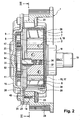
- einen Schnitt senkrecht zur Axialen gemäß Linie II-II in
Fig. 2 ; - Fig. 4
- eine perspektivische Ansicht einer Dichtplatte mit Stufenkulisse zur Verriegelung in Frühstellung;
- Fig. 5
- eine perspektivische Ansicht einer Dichtplatte mit Stufenkulisse zur Verriegelung in Mittenstellung.
- In den Figuren ist eine kombinierte Verriegelungs- und Drehwinkelbegrenzungseinrichtung eines Flügelzellen-Nockenwellenverstellers zur variablen Einstellung der Steuerzeiten der Gaswechselventile einer Brennkraftmaschine dargestellt.
- Der Flügelzellen-Nockenwellenversteller umfasst als Antriebsteil einen mit einer Kurbelwelle über ein Antriebsrad 24 in Antriebsverbindung stehenden Außenrotor 1 und als Abtriebsteil einen innerhalb des Außenrotors 1 konzentrisch angeordneten Innenrotor 2, im Weiteren als Rotor bezeichnet, welcher drehfest mit einer Nockenwelle 19 verbunden ist.
- Der Außenrotor 1 ist seinerseits aus mehreren drehfest miteinander verbundenen Bauteilen aufgebaut. So umfasst der Außenrotor 1 einen beispielsweise als Blechteil ausgebildeten Stator 3, dessen Innenmantelfläche 4 mit mehreren radialen Ausnehmungen 5 versehen ist, die jeweils von radialen Seitenwänden 6, 7 begrenzt sind. Die Innenmantelfläche 4 des Stators 3 ist demnach in Umfangsrichtung sich erstreckende, innere Umfangswände 27 und in Umfangsrichtung sich erstreckende, äußere Umfangswände 28, sowie die inneren und äußeren Umfangswände jeweils miteinander verbindende, radiale Seitenwände 6, 7, unterteilbar. Der Stator 3 ist über seine inneren Umfangswände 27, die einer Außenmantelfläche 8 des Rotors 2 anliegen, drehbar auf dem Rotor 2 gelagert. Der Stator 3 kann beispielsweise aus Stahlblech mittels eines spanlosen Umformprozesses, wie ein Tiefziehverfahren, hergestellt sein.
- Die Ausnehmungen 5 formen zusammen mit einer Außenmantelfläche 8 des Rotors 2 und zwei axialen Dichtflächen, welche weiter unten näher erläutert werden, in Umfangsrichtung verteilt angeordnete Druckräume 10.
- In jeden Druckraum 10 ragt, ausgehend vom Rotor 2, radial auswärts ein Flügel 11, wodurch die Druckräume 10 jeweils in zwei gegeneinander wirkende Druckkammern 12, 13 geteilt werden, von denen die eine in Drehrichtung des Rotors 2 vorläuft und die andere entsprechend nachläuft. Im gezeigten Beispiel eines Flügelzellen-Nockenwellenverstellers sind die Flügel 11 jeweils in Axialnuten 29 aufgenommen, die in der Außenmantelfläche 8 des Rotors 2 ausgebildet sind. Am Nutgrund einer jeden Axialnut 29 ist ein den Flügel 11 nach radial außen belastendes Federelement angeordnet, wodurch bewirkt wird, dass die Flügel 11 der äußeren Umfangswand 28 des Stators 3 dichtend anliegen. Gleichermaßen wäre es möglich, die Flügel 11 in Form von Vorsprüngen einteilig mit dem Rotor 2 auszubilden.
- Der Außenrotor 1 umfasst weiterhin ein den Stator 3 und den Rotor 2 druckdicht kapselndes Gehäuse, das aus einem topfförmigen ersten Gehäuseteil 15 und einem mit diesem verbundenen, scheibenförmigen zweiten Gehäuseteil 16 zusammengesetzt ist. Die beiden Gehäuseteile 15, 16 können beispielsweise aus Stahlblech mittels eines spanlosen Umformprozesses, wie ein Tiefziehverfahren, hergestellt sein.
- Das erste Gehäuseteil 15 ist auf einer der Nockenwelle 19 zugewandten Seite mit einer Bodenfläche 17 versehen, in der ein durchstellter Kragen 18 zur Aufnahme der Nockenwelle 19 ausgebildet ist. Der Stator 3 ist zentriert innerhalb des ersten Gehäuseteils 15 aufgenommen. Die Innenmantelfläche 30 des ersten Gehäuseteils 15 ist mit radialen Vorsprüngen 20 versehen, die in jeweilige Vertiefungen zwischen den Seitenwänden 6, 7 der Innenmantelfläche 4 des Stators 3 greifen, wodurch eine in Umfangsrichtung formschlüssige Verbindung zwischen dem Stator 3 und dem ersten Gehäuseteil 15 hergestellt wird. Auf der der Nockenwelle 19 abgewandten Seite des ersten Gehäuseteils 15 ist ein radialer erster Flansch 21 mit axialen Bohrungen 22 geformt.
- Das zum ersten Gehäuseteil 15 koaxial angeordnete, zweite Gehäuseteil 16 formt einen zweiten Flansch 31, der komplementär zum ersten Flansch 21 des ersten Gehäuseteils 15 ausgebildet ist. Ferner ist der zweite Flansch 31 mit axialen Bohrungen versehen, die axial fluchtend zu den axialen Bohrungen 22 des ersten Flansches 21 angeordnet sind. Die beiden Gehäuseteile 15, 16 sind durch Verbindungsmittel, hier Schrauben 23, die durch die fluchtenden axialen Bohrungen hindurch greifen, miteinander verbunden.
- Das Antriebsrad 24 ist über die Schrauben 23, welche zusätzlich durch Bohrungen 14 hindurch greifen, welche an einem sich radial einwärts erstreckenden Bund 48 des Antriebsrads 24 ausgebildet sind, mit den beiden Gehäuseteilen 15, 16 drehfest verbunden.
- Weiterhin ist im zweiten Gehäuseteil 16 eine zentrale Bohrung 26 ausgebildet, welche ermöglicht, den Rotor 2 mittels einer Zentralschraube an der Nockenwelle 19 zu befestigen. Die Bohrung 26 ist mittels eines Deckels 25 nach außen verschlossen.
- Die oben erwähnten axialen Dichtflächen zur Formung der in Umfangsrichtung verteilt angeordneten Druckräume 10 werden durch eine auf der abgewandten Seite der Nockenwelle 19 angeordnete Dichtplatte 9 und auf der zugewandten Seite der Nockenwelle 19 durch die Bodenfläche 17 des ersten Gehäuseteils 15 gebildet, welche die Druckräume bzw. Druckkammern in axialer Richtung druckdicht verschließen.
- Die Dichtplatte 9 ist drehfest mit dem ersten Gehäuseteil 15 verbunden. Zur drehfesten Verbindung mit dem Stator 3 ist eine radiale Außenmantelfläche 38 der Dichtplatte 9 mit Einformungen 39 versehen, in welche die von der Innenmantelfläche 30 des ersten Gehäuseteils 15 geformten Vorsprünge 20 eingreifen. Die Dichtplatte 9 dient weiterhin zum Ausgleichen etwaiger Toleranzen zwischen den beiden Gehäuseteilen 15, 16. Alternativ könnte die Abdichtung der Druckräume bzw. Druckkammern nach außen durch das zweite Gehäuseteil 16 erfolgen.
- In die Druckkammern 12, 13 münden Druckmittelleitungen, durch welche Druckmittel zu den Druckkammern zugeführt oder von diesen abgeleitet werden kann. Durch gezielte Beaufschlagung mit Druckmittel kann zwischen dem Druckkammerpaar eines jeden Druckraums ein Druckgefälle aufgebaut werden, das ein Verschwenken der Flügel 11 und somit eine Änderung der relativen Drehlage des Rotors 2 zum Stator 3 bewirkt. Bei einem gleichen hydraulischen Druck zwischen einem Druckkammerpaar jedes Druckraums bleibt die relative Drehlage zwischen Rotor 2 und Stator 3 erhalten.
- Um bei ungenügender Druckmittelversorgung eine Übertragung von Wechsel- und Schleppmomenten der Nockenwelle 19 auf den Stator 3 zu vermeiden, ist eine Verriegelungseinrichtung zur Verriegelung von Rotor 2 und Stator 3 in einer gewünschten Drehlage vorgesehen. Diese umfasst einen in einer Ausnehmung 32 der Rotors 2 aufgenommenen Kolben 33, der durch ein Federelement 34 in Richtung der Dichtplatte 9 gedrängt wird. In einer wählbaren relativen Drehlage des Rotors 2 zum Stator 3 kann der Kolben 33 in eine von der Dichtplatte 9 geformte Aussparung bzw. Kulisse eingreifen, wodurch eine formschlüssige Verbindung zwischen dem Rotor 2 und der mit dem Stator 3 drehfest verbundenen Dichtplatte 9 hergestellt wird.
- Um bei ungenügender Druckmittelversorgung ein Anschlagen der Flügel 11 an die Seitenwände 6, 7 der Druckräume 10 zu verhindern, ist zudem eine Drehwinkelbegrenzungseinrichtung zur Einstellung relativer Enddrehlagen von Rotor 2 zu Stator 3 in den beiden Drehrichtungen vorgesehen.
- Um sowohl eine Verriegelung von Rotor 2 und Stator 3 als auch eine Einstellung der relativen Enddrehlagen von Rotor 2 zu Stator 3 mit dem gleichen Kolben 33 zu erreichen, ist die Dichtplatte 9 mit einer in axialer Richtung gestuften Kulisse 37 für den Kolben 33 versehen. Die Stufenkulisse 37 ist als radiale Ausnehmung der radialen Begrenzungswand 53 einer zentralen Bohrung 36 der Dichtplatte 9 geformt. Die zentrale Bohrung 36 ermöglicht eine Befestigung des Rotors 2 mittels einer Zentralschraube an der Nockenwelle 19.
- Die Stufenkulisse 37 setzt sich aus zwei in axialer Richtung zueinander versetzten Kulissen zusammen: eine mit größerem axialen Abstand zur Nockenwelle 19 angeordnete erste Kulisse 35 ("Riegelkulisse"), welche der formschlüssigen Aufnahme des Kolbens 33 dient, und eine mit geringerem axialen Abstand zur Nockenwelle 19 angeordnete zweite Kulisse 40 ("Drehwinkelbegrenzungskulisse"), welcher der Einstellung der maximalen relativen Enddrehlagen von Rotor 2 zu Stator 3 in den beiden Drehrichtungen des Rotors 2 dient.
- Die Riegelkulisse 35 und die Drehwinkelbegrenzungskulisse 40 sind in axialer Richtung durch die Stufe 41 voneinander getrennt. Während die Riegelkulisse 35 in Form einer Durchbrechung der Dichtplatte 9 ausgebildet ist, ist die Drehwinkelbegrenzungskulisse 40 lediglich als axiale Tiefung der der Nockenwelle 19 zugewandten Dichtfläche 42 der Dichtplatte 9 geformt.
- Die radialen Begrenzungswandabschnitte 43, 44 der Riegelkulisse 35 befinden sich innerhalb einer (gedachten) axialen Verlängerung der radialen Begrenzungswandabschnitte 45, 46 der Drehwinkelbegrenzungskulisse 40.
- Die Riegelkulisse 35 erstreckt sich derart in Umfangsrichtung, dass deren radiale Begrenzungswandabschnitte 43, 44 der Außenfläche des in die Riegelkulisse 35 eingreifenden Kolbens 33 in Umfangsrichtung anliegen, so dass durch den zugleich in der Ausnehmung 32 des Rotors 2 aufgenommenen und in die Riegelkulisse 35 eingreifenden Kolben 33 eine formschlüssige Verbindung in Umfangsrichtung zwischen dem Rotor 2 und dem Stator 3 hergestellt wird.
- Die beiden radialen Begrenzungswandabschnitte 43, 44 der Riegelkulisse 35 sind durch einen kreissegmentförmigen, sich im Wesentlichen in Umfangsrichtung erstreckenden Begrenzungswandabschnitt 49 miteinander verbunden.
- Der zylindrische Kolben 33 ist im Hohlraum 54 einer Kolbenhülse 51 verschiebbar aufgenommen. Die in die Drehwinkelbegrenzungskulisse 40 eingreifende Kolbenhülse 51 ist ihrerseits in Umfangsrichtung verschiebbar in einer nicht näher dargestellten Aussparung zwischen Dichtplatte 9 und Rotor 2 aufgenommen. Der Kolben 33 greift in Verriegelungsposition durch die Kolbenhülse 51 hindurch. In Entriegelungsposition greift der Kolben 33 in die Kolbenhülse 51 ein. Die Kolbenhülse 51 wird mit dem in Entriegelungsposition in sie eingreifenden Kolben 33 bei einer Änderung der relativen Drehlage von Rotor 2 zu Stator 3 in Umfangsrichtung mitbewegt.
- Im Unterschied zur Riegelkulisse 35 erstreckt sich die Drehwinkelbegrenzungskulisse 40 derart in Umfangsrichtung, dass deren radialen Begrenzungswandabschnitte 45, 46 der Außenfläche des zugleich in der Ausnehmung 32 des Rotors 2 aufgenommenen und (nur) in die Drehwinkelbegrenzungskulisse eingreifenden Kolbens 33 in Umfangsrichtung nicht anliegen, sondern vielmehr Anschläge für den Kolben 33 beziehungsweise die zwischengeschaltete Kolbenhülse 51 zur Definition jeweiliger maximaler Enddrehlagen von Rotor 2 zu Stator 3 bilden. In den beiden relativen Endrehlagen kommt die Außenmantelfläche 52 der Kolbenhülse 51 zur Anlage gegen die radialen Begrenzungswandabschnitte 45, 46 der Drehwinkelbegrenzungskulisse 40. Insofern kann durch den umfänglichen Abstand der radialen Begrenzungswandabschnitte 45, 46 der Drehwinkelbegrenzungskulisse 40 ein maximaler Drehwinkel zur Drehverstellung von Rotor 2 zu Stator 3 eingestellt werden. Die radialen Begrenzungswandabschnitte 45, 46 der Drehwinkelbegrenzungskulisse 40 sind durch einen sich im Wesentlichen in Umfangsrichtung erstreckenden Begrenzungswandabschnitt 50 miteinander verbunden.
- Das Vorsehen der Kolbenhülse 51 hat den Vorteil, dass bei Verriegelung in Endrehlage kein Reibmoment zwischen der Außenmantelfläche des Kolbens 33 und den radialen Begrenzungswandabschnitten 45, 46 der Drehwinkelbegrenzungskulisse 40 auftreten kann, so dass der Kolben 33 ohne Gefahr einer Klemmung/Verkeilung sicher in die Riegelkulisse 35 verschoben werden kann.
- Der Kolben 33 kann durch einen Verschiebungsmechanismus zwischen einer Verriegelungsposition, in der er in die Riegelkulisse 35 eingreift, und einer Entriegelungsposition, in der er unter Zwischenschaltung der Kolbenhülse 51 (nur) in die Drehwinkelbegrenzungskulisse 40 eingreift, verschoben werden.
- Im gezeigten Beispiel wird der Kolben 33 durch das Federelement 34 in die Riegelkulisse 35 gedrängt. Lediglich in einer wählbaren relativen Drehlage (Basisposition) des Rotors 2 zum Stator 3 kann der Kolben 33 in die Riegelkulisse 35 eingreifen.
- In Basisposition kommuniziert die Riegelkulisse 35 mit wenigstens einer Druckmittelleitung zum Zu- bzw. Abführen von Druckmittel zu bzw. von der Riegelkulisse 35, so dass eine axiale Stirnfläche des Kolbens 33 hydraulisch beaufschlagbar ist und der Kolben 33 entgegen der Federkraft des Federelements 34 aus der Riegelkulisse 35 gedrückt werden kann.
- Der Verschiebungsmechanismus ist hierbei so ausgebildet, dass der Kolben 33 infolge hydraulischer Beaufschlagung lediglich so weit in Richtung seiner Ausnehmung 32 im Rotor 2 gedrängt werden kann, dass er in Entriegelungsposition stets noch in die Drehwinkelbegrenzungskulisse 40 bzw. die in die Drehwinkelbegrenzungskulisse 40 eingreifende Riegelhülse 51 eingreift, um im Zusammenwirken mit der von ihm mitgeführten Kolbenhülse 51 eine Drehwinkelbegrenzung zwischen Rotor 2 und Stator 3 zu realisieren.
- In
Fig. 4 sind die in Rotor-Drehrichtung vorlaufenden, radialen Begrenzungswandabschnitte 43, 45 der Riegelkulisse 35 und der Drehwinkelbegrenzungskulisse 40 in etwa axial fluchtend zueinander angeordnet. Dies bewirkt eine Verriegelung des Rotors 2 in Frühstellung, bei der die Flügel 41 in Verriegelungsposition näher zu den in Rotor-Drehrichtung vorlaufenden Seitenwänden 6 als zu den entsprechend nachlaufenden Seitenwänden 7 der Druckräume 10 angeordnet sind. - Zur Verstellung des Rotors in Frühstellung ist ein Federelement 47 angeordnet, das sowohl mit dem Außenrotor 1 als auch mit dem Innenrotor 2 verbunden ist. Die Kräfte die das Federelement 47 auf den Rotor 2 ausübt sind so gerichtet, dass Rotor 2 und Stator 3 bei ungenügender Druckmittelbefüllung der Druckkammern in eine solche relative Drehlage (Basisposition) verdreht werden, bei der der Kolben 33 in die Riegelkulisse 35 eingreifen kann.
- Anstelle einer Verriegelung in Frühstellung wäre gleichermaßen eine Verriegelung in Spätstellung möglich. Zu diesem Zweck ist es lediglich erforderlich, die Stufenkulisse 37 so auszubilden, dass die in Rotor-Drehrichtung nachlaufenden, radialen Begrenzungswandabschnitte 44, 46 der Riegelkulisse 35 und der Drehwinkelbegrenzungskulisse 40 in etwa axial fluchtend zueinander angeordnet sind.
- Anstelle einer Verriegelung in Früh- oder Spätstellung wäre gleichermaßen eine Verriegelung in Mittenstellung möglich.
-
Fig. 5 veranschaulicht eine Dichtplatte 9 eines weiteren Ausführungsbeispiels der erfindungsgemäßen Verriegelungsvorrichtung mit Verriegelung in Mittenstellung. Um eine Mittenverriegelung zu bewirken, ist es lediglich erforderlich, dass die radialen Begrenzungswandabschnitte 43, 44 der Riegelkulisse 35 in Umfangsrichtung in etwa mittig zwischen einer (gedachten) axialen Verlängerung der radialen Begrenzungswandabschnitte 45, 46 der Drehwinkelbegrenzungskulisse 40 angeordnet sind. - In vorteilhafter Weise ist die Dichtplatte 9 aus einem härtbaren Stahl hergestellt, so dass diese nach der Formgebung einem Härteverfahren unterzogen werden kann, um sicherzustellen, dass die über den Kolben 33 übertragenen Kräfte funktionssicher aufgenommen werden können.
- Obgleich die Riegelkulisse 35 in
Fig. 4 und 5 in Form einer Durchbrechung ausgebildet ist, wäre es gleichermaßen möglich, dass sie lediglich in Form einer axialen Tiefung der Dichtfläche 42 der Dichtplatte 9 ausgebildet ist. - Obgleich die Stufenkulisse 37 in
Fig. 4 und 5 in der Dichtplatte 9 ausgebildet ist, wäre es gleichermaßen möglich, die Stufenkulisse im zweiten Gehäuseteil 16 oder einem anderen Bauteil des Außenrotors 1 auszubilden - Obgleich ein Verschiebungsmechanismus veranschaulicht ist, bei dem der federkraftbeaufschlagte Kolben 33 hydraulisch entriegelbar ist, kann gleichermaßen ein anderer Verschiebungsmechanismus, wie beispielsweise eine Verschiebung des Kolbens 33 durch einen elektrischen Stellmotor, vorgesehen sein.
-
- 1
- Außenrotor
- 2
- Innenrotor (Rotor)
- 3
- Stator
- 4
- Innenmantelfläche
- 5
- Ausnehmung
- 6
- Seitenwand
- 7
- Seitenwand
- 8
- Außenmantelfläche
- 9
- Dichtplatte
- 10
- Druckraum
- 11
- Flügel
- 12
- Druckkammer
- 13
- Druckkammer
- 14
- Bohrung
- 15
- erstes Gehäuseteil
- 16
- zweites Gehäuseteil
- 17
- Bodenfläche
- 18
- Kragen
- 19
- Nockenwelle
- 20
- Vorsprung
- 21
- erster Flansch
- 22
- Bohrung
- 23
- Schraube
- 24
- Antriebsrad .
- 25
- Deckel
- 26
- Bohrung
- 27
- innere Umfangswand
- 28
- äußere Umfangswand
- 29
- Axialnut
- 30
- Innenmantelfläche
- 31
- zweiter Flansch
- 32
- Ausnehmung
- 33
- Kolben
- 34
- Federelement
- 35
- Riegelkulisse
- 36
- Bohrung
- 37
- Stufenkulisse
- 38
- Außenmantelfläche
- 39
- Einformung
- 40
- Drehwinkelbegrenzungskulisse
- 41
- Stufe
- 42
- Dichtfläche
- 43
- radialer Begrenzungswandabschnitt
- 44
- radialer Begrenzungswandabschnitt
- 45
- radialer Begrenzungswandabschnitt
- 46
- radialer Begrenzungswandabschnitt
- 47
- Federelement
- 48
- Bund
- 49
- umfänglicher Begrenzungswandabschnitt
- 50
- umfänglicher Begrenzungswandabschnitt
- 51
- Kolbenhülse
- 52
- Außenmantelfläche der Kolbenhülse
- 53
- radiale Begrenzungswand
- 54
- Hohlraum
Claims (16)
- Kombinierte Verriegelungs- und Drehwinkelbegrenzungseinrichtung zur Verriegelung und Einstellung einer maximalen Drehverstellbarkeit eines kurbelwellenfesten Antriebsteils (1) und eines zu diesem drehbar verstellbaren, nockenwellenfesten Abtriebsteils (2) eines Nockenwellenverstellers für eine Brennkraftmaschine, mit einem in dem An- oder Abtriebsteil aufgenommenen, durch einen Verschiebungsmechanismus verschiebbaren Riegel (33), einer in dem entsprechend anderen Teil geformten Riegelkulisse (35), durch die der Riegel (33) in Umfangsrichtung formschlüssig aufnehmbar ist, und einer in dem entsprechend anderen Teil geformten Drehwinkelbegrenzungskulisse (40), durch die der Riegel (33) in Umfangsrichtung mit Abstand aufnehmbar ist, wobei in Umfangsrichtung beabstandete, im Wesentlichen radiale Begrenzungswandabschnitte (45, 46) als Anschläge für den Riegel zur Einstellung einer maximalen Drehverstellbarkeit von An- und Abtriebsteil dienen, wobei die Riegelkulisse, die Drehwinkelbegrenzungskulisse und der Riegel derart angeordnet sind, dass der Riegel durch den Verschiebungsmechanismus in eine Verriegelungsposition, in der er von der Riegelkulisse führbar ist, und in eine Entriegelungsposition, in der er von der Drehwinkelbegrenzungskulisse führbar ist, verschiebbar ist,
dadurch gekennzeichnet, dass
die Riegelkulisse (35) innerhalb einer insbesondere axialen Verlängerung in Riegelverschiebungsrichtung der Drehwinkelbegrenzungskulisse (40) angeordnet ist. - Kombinierte Verriegelungs- und Drehwinkelbegrenzungseinrichtung nach Anspruch 1, dadurch gekennzeichnet, dass die Riegelkulisse (35) und die Drehwinkelbegrenzungskulisse (40) in axialer Richtung versetzt angeordnet sind.
- Kombinierte Verriegelungs- und Drehwinkelbegrenzungseinrichtung nach einem der Ansprüche 1 oder 2, dadurch gekennzeichnet, dass die Riegelkulisse (35) und die Drehwinkelbegrenzungskulisse (40) in Form einer gestuften Kulisse (37) ausgebildet sind.
- Kombinierte Verriegelungs- und Drehwinkelbegrenzungseinrichtung nach einem der Ansprüche 2 oder 3, dadurch gekennzeichnet, dass ein in Drehrichtung des Abtriebsteils (2) nachlaufender, im Wesentlichen radialer Begrenzungswandabschnitt (44) der Riegelkulisse (35) in Umfangsrichtung näher zu einer axialen Verlängerung eines in Drehrichtung des Abtriebsteils (2) nachlaufenden, im Wesentlichen radialen Begrenzungswandabschnitts (46) der Drehwinkelbegrenzungskulisse (40) als zu einer axialen Verlängerung eines in Drehrichtung des Abtriebsteils (2) vorlaufenden, im Wesentlichen radialen Begrenzungswandabschnitts (45) der Drehwinkelbegrenzungskulisse (40) angeordnet ist.
- Kombinierte Verriegelungs- und Drehwinkelbegrenzungseinrichtung nach Anspruch 4, dadurch gekennzeichnet, dass ein in Drehrichtung des Abtriebsteils (2) nachlaufender, im Wesentlichen radialer Begrenzungswandabschnitt (44) der Riegelkulisse (35) axial fluchtend zu einem in Drehrichtung des Abtriebsteils (2) nachlaufenden, im Wesentlichen radialen Begrenzungswandabschnitt (46) der Drehwinkelbegrenzungskulisse (40) angeordnet ist.
- Kombinierte Verriegelungs- und Drehwinkelbegrenzungseinrichtung nach einem der Ansprüche 2 oder 3, dadurch gekennzeichnet, dass ein in Drehrichtung des Abtriebsteils (2) vorlaufender, im Wesentlichen radialer Begrenzungswandabschnitt (43) der Riegelkulisse (35) in Umfangsrichtung näher zu einer axialen Verlängerung eines in Drehrichtung des Abtriebsteils (2) vorlaufenden, im Wesentlichen radialen Begrenzungswandabschnitts (45) der Drehwinkelbegrenzungskulisse (40) als zu einer axialen Verlängerung eines in Drehrichtung des Abtriebsteils nachlaufenden, im Wesentlichen radialen Begrenzungswandabschnitts (46) der Drehwinkelbegrenzungskulisse (40) angeordnet ist.
- Kombinierte Verriegelungs- und Drehwinkelbegrenzungseinrichtung nach Anspruch 6, dadurch gekennzeichnet, dass ein in Drehrichtung des Abtriebsteils (2) vorlaufender, im Wesentlichen radialer Begrenzungswandabschnitt (43) der Riegelkulisse (35) axial fluchtend zu einem in Drehrichtung des Abtriebsteils (2) vorlaufenden, im Wesentlichen radialen Begrenzungswandabschnitt (45) der Drehwinkelbegrenzungskulisse (40) angeordnet ist.
- Kombinierte Verriegelungs- und Drehwinkelbegrenzungseinrichtung nach einem der Ansprüche 2 oder 3, dadurch gekennzeichnet, dass die Riegelkulisse (35) im Wesentlichen mittig zwischen den axialen Verlängerungen eines in Drehrichtung des Abtriebsteils (2) nachlaufenden, im Wesentlichen radialen Begrenzungswandabschnitts (46) und eines in Drehrichtung des Abtriebsteils (2) vorlaufenden, im Wesentlichen radialen Begrenzungswandabschnitts (45) der Drehwinkelbegrenzungskulisse (40) angeordnet ist.
- Kombinierte Verriegelungs- und Drehwinkelbegrenzungseinrichtung nach einem der Ansprüche 1 bis 8, dadurch gekennzeichnet, dass die Riegel- und die Drehwinkelbegrenzungskulisse (35, 40) im Antriebsteil (1) ausgebildet sind.
- Kombinierte Verriegelungs- und Drehwinkelbegrenzungseinrichtung nach Anspruch 9, dadurch gekennzeichnet, dass die Riegel- und die Drehwinkelbegrenzungskulisse (35, 40) in einem zwischen einem Gehäusebauteil (16) und dem Abtriebsteil (2) angeordneten Dichtelement (9) ausgebildet sind.
- Kombinierte Verriegelungs- und Drehwinkelbegrenzungseinrichtung nach Anspruch 10, dadurch gekennzeichnet, dass die Riegel- und die Drehwinkelbegrenzungskulisse (35, 40) jeweils in Form einer radialen Ausnehmung einer zentralen Bohrung (36) des Dichtelements (9) ausgebildet sind.
- Kombinierte Verriegelungs- und Drehwinkelbegrenzungseinrichtung nach einem der Ansprüche 1 bis 11, dadurch gekennzeichnet, dass der Riegel (33) unter Zwischenschaltung eines in die Drehwinkelbegrenzungskulisse (40) eingreifenden Gleitstücks (51) von der Drehwinkelbegrenzungskulisse (40) geführt ist, wobei der Riegel (33) in seiner Verschiebungsrichtung verschiebbar in dem Gleitstück (51) aufgenommen ist.
- Kombinierte Verriegelungs- und Drehwinkelbegrenzungseinrichtung nach Anspruch 12, dadurch gekennzeichnet, dass das Gleitstück (51) in Hülsenform ausgebildet ist.
- Nockenwellenversteller mit einer kombinierten Verriegelungs- und Drehwinkelbegrenzungseinrichtung nach einem der Ansprüche 1 bis 13.
- Brennkraftmaschine mit einer kombinierten Verriegelungs- und Drehwinkelbegrenzungseinrichtung nach einem der Ansprüche 1 bis 13.
- Kraftfahrzeug mit einer Brennkraftmaschine nach Anspruch 15.
Applications Claiming Priority (2)
| Application Number | Priority Date | Filing Date | Title |
|---|---|---|---|
| DE102007004184A DE102007004184A1 (de) | 2007-01-27 | 2007-01-27 | Kombinierte Verriegelungs- und Drehwinkelbegrenzungseinrichtung eines Nockenwellenverstellers |
| PCT/EP2007/064300 WO2008089876A1 (de) | 2007-01-27 | 2007-12-20 | Kombinierte verriegelungs- und drehwinkelbegrenzungseinrichtung eines nockenwellenverstellers |
Publications (2)
| Publication Number | Publication Date |
|---|---|
| EP2118455A1 EP2118455A1 (de) | 2009-11-18 |
| EP2118455B1 true EP2118455B1 (de) | 2011-10-12 |
Family
ID=39284149
Family Applications (1)
| Application Number | Title | Priority Date | Filing Date |
|---|---|---|---|
| EP07857921A Not-in-force EP2118455B1 (de) | 2007-01-27 | 2007-12-20 | Kombinierte verriegelungs- und drehwinkelbegrenzungseinrichtung eines nockenwellenverstellers |
Country Status (6)
| Country | Link |
|---|---|
| US (1) | US8166934B2 (de) |
| EP (1) | EP2118455B1 (de) |
| CN (1) | CN101600856B (de) |
| AT (1) | ATE528487T1 (de) |
| DE (1) | DE102007004184A1 (de) |
| WO (1) | WO2008089876A1 (de) |
Cited By (1)
| Publication number | Priority date | Publication date | Assignee | Title |
|---|---|---|---|---|
| DE102012206072B4 (de) * | 2011-04-18 | 2017-08-03 | Denso Corporation | Ventilsteuervorrichtung |
Families Citing this family (8)
| Publication number | Priority date | Publication date | Assignee | Title |
|---|---|---|---|---|
| DE102007056550A1 (de) * | 2007-11-23 | 2009-05-28 | Schaeffler Kg | Modular aufgebauter Nockenwellenversteller mit Ketten- oder Riemenrad |
| US8171903B2 (en) | 2008-12-03 | 2012-05-08 | Hyundai Motor Company | Intermediate lock pin type variable valve timing unit for vehicle and continuously variable valve timing device using the same |
| DE102011085693A1 (de) * | 2011-11-03 | 2013-05-08 | Schaeffler Technologies AG & Co. KG | Nockenwellenversteller |
| DE102012206338B4 (de) * | 2012-04-18 | 2021-06-02 | Schaeffler Technologies AG & Co. KG | Nockenwellenversteller mit Stator-Deckel-Einheit zur automatischen Einstellung eines Verriegelungsspiels |
| DE102013203245A1 (de) * | 2013-02-27 | 2014-08-28 | Schaeffler Technologies Gmbh & Co. Kg | Statortopf mit Einlegescheibe zur Reduzierung des Axiallagerspiels |
| DE102014009091A1 (de) * | 2014-06-19 | 2015-12-24 | Hilite Germany Gmbh | Schwenkmotorversteller für eine Nockenwelle |
| DE102016107986A1 (de) | 2015-11-04 | 2017-05-04 | Hilite Germany Gmbh | Hydraulikventil und Pleuel mit einem Hydraulikventil |
| CN118583023A (zh) * | 2024-08-06 | 2024-09-03 | 国营川西机器厂 | 用于航空发动机主燃油泵调节器凸轮轴向位移的测量装置 |
Family Cites Families (15)
| Publication number | Priority date | Publication date | Assignee | Title |
|---|---|---|---|---|
| EP0799977B1 (de) * | 1996-04-04 | 2000-12-13 | Toyota Jidosha Kabushiki Kaisha | Variable Ventilzeitsteuervorrichtung für Brennkraftmaschine |
| JP3918971B2 (ja) | 1998-04-27 | 2007-05-23 | アイシン精機株式会社 | 弁開閉時期制御装置 |
| DE19860418B4 (de) * | 1998-12-28 | 2008-09-11 | Schaeffler Kg | Vorrichtung zum Verändern der Steuerzeiten von Gaswechselventilen einer Brennkraftmaschine, insbesondere Nockenwellen-Verstelleinrichtung mit Flügelrad |
| JP4142204B2 (ja) * | 1999-05-19 | 2008-09-03 | 本田技研工業株式会社 | 弁作動特性可変装置 |
| JP4440384B2 (ja) | 1999-09-24 | 2010-03-24 | アイシン精機株式会社 | 弁開閉時期制御装置 |
| JP4207141B2 (ja) * | 2000-06-09 | 2009-01-14 | 株式会社デンソー | バルブタイミング調整装置 |
| JP2002122009A (ja) * | 2000-08-09 | 2002-04-26 | Mitsubishi Electric Corp | バルブタイミング調整装置 |
| DE10213831A1 (de) * | 2001-03-28 | 2002-11-07 | Denso Corp | Variables Ventilsteuerzeitengerät |
| JP2002295275A (ja) * | 2001-03-29 | 2002-10-09 | Denso Corp | バルブタイミング調整装置 |
| JP3736489B2 (ja) * | 2002-03-27 | 2006-01-18 | 株式会社デンソー | バルブタイミング調整装置の制御方法 |
| JP4177197B2 (ja) * | 2003-08-08 | 2008-11-05 | 株式会社日立製作所 | 内燃機関のバルブタイミング制御装置 |
| DE10354586A1 (de) | 2003-11-21 | 2005-06-16 | Ina-Schaeffler Kg | Hydraulischer Nockenwellenversteller und Verfahren zum Betreiben desselben |
| JP2006170085A (ja) * | 2004-12-16 | 2006-06-29 | Aisin Seiki Co Ltd | 弁開閉時期制御装置及び最低トルクの設定方法 |
| EP1681442A1 (de) * | 2005-01-18 | 2006-07-19 | Delphi Technologies, Inc. | Nockenwellenversteller zur Steuerung der Verstellung zwischen einer Nockenwelle und einer Ventilsteuerung |
| DE102007015064A1 (de) * | 2007-03-29 | 2008-10-02 | Schaeffler Kg | Nockenwellenversteller und Verfahren zur Einstellung einer Begrenzungsstellung für einen Nockenwellenversteller |
-
2007
- 2007-01-27 DE DE102007004184A patent/DE102007004184A1/de not_active Withdrawn
- 2007-12-20 AT AT07857921T patent/ATE528487T1/de active
- 2007-12-20 US US12/524,505 patent/US8166934B2/en not_active Expired - Fee Related
- 2007-12-20 EP EP07857921A patent/EP2118455B1/de not_active Not-in-force
- 2007-12-20 WO PCT/EP2007/064300 patent/WO2008089876A1/de active Application Filing
- 2007-12-20 CN CN2007800505288A patent/CN101600856B/zh not_active Expired - Fee Related
Cited By (1)
| Publication number | Priority date | Publication date | Assignee | Title |
|---|---|---|---|---|
| DE102012206072B4 (de) * | 2011-04-18 | 2017-08-03 | Denso Corporation | Ventilsteuervorrichtung |
Also Published As
| Publication number | Publication date |
|---|---|
| ATE528487T1 (de) | 2011-10-15 |
| US8166934B2 (en) | 2012-05-01 |
| DE102007004184A1 (de) | 2008-07-31 |
| EP2118455A1 (de) | 2009-11-18 |
| US20100101516A1 (en) | 2010-04-29 |
| WO2008089876A1 (de) | 2008-07-31 |
| CN101600856B (zh) | 2013-06-05 |
| CN101600856A (zh) | 2009-12-09 |
Similar Documents
| Publication | Publication Date | Title |
|---|---|---|
| EP2118455B1 (de) | Kombinierte verriegelungs- und drehwinkelbegrenzungseinrichtung eines nockenwellenverstellers | |
| DE19914767C2 (de) | Ventilzeit-Steuerungseinrichtung | |
| EP1896699B1 (de) | Steuerventil für eine vorrichtung zur variablen einstellung der steuerzeiten von gaswechselventilen einer brennkraftmaschine | |
| EP2415979B1 (de) | Nockenwellenversteller | |
| EP2527607B1 (de) | Vorrichtung zur Verstellung der relativen Drehwinkelposition geschachtelter Nockenwellen | |
| DE102004038252A1 (de) | Steuerventil für eine Vorrichtung zur Veränderung der Steuerzeiten einer Brennkraftmaschine | |
| EP1832723B1 (de) | Ventilsteuerung zur Einstellung des Hubes von Ventilen in einer Brennkraftmaschine | |
| DE102004036096A1 (de) | Steuerventil für eine Vorrichtung zur Veränderung der Steuerzeiten einer Brennkraftmaschine | |
| DE102008011916A1 (de) | Nockenwellenversteller mit Rasterverriegelungseinrichtung | |
| DE112016000836T5 (de) | Nockenwellenphasenversteller | |
| DE102014212617A1 (de) | Mittenverriegelung für einen Nockenwellenversteller | |
| WO2013189621A1 (de) | Steuerventil eines nockenwellenverstellers | |
| DE10055334C2 (de) | Vorrichtung zur relativen Drehwinkelverstellung einer Nockenwelle einer Brennkraftmaschine zu einem Antriebsrad | |
| DE102008051732A1 (de) | Vorrichtung zur variablen Einstellung der Steuerzeiten von Gaswechselventilen einer Brennkraftmaschine | |
| DE102012203114A1 (de) | Einlegeteil für Nockenwellenversteller mit Mittenverriegelung | |
| DE10339668B4 (de) | Ventilzeitsteuervorrichtung | |
| DE102010009393A1 (de) | Vorrichtung zur variablen Einstellung der Steuerzeiten von Gaswechselventilen einer Brennkraftmaschine | |
| EP3158173B1 (de) | Schwenkmotorversteller für eine nockenwelle | |
| WO2007093480A1 (de) | Vorrichtung zur variablen einstellung der steuerzeiten von gaswechselventilen einer brennkraftmaschine | |
| DE102015214623A1 (de) | Nockenwellenverstellvorrichtung | |
| EP2362074B1 (de) | Vorrichtung zur variablen Einstellung der Steuerzeiten von Gaswechselventilen einer Brennkraftmaschine | |
| DE102008011116A1 (de) | Nockenwellenversteller mit Steuerelement | |
| DE102004019190A1 (de) | Nockenwellenversteller | |
| DE102008032025A1 (de) | Riemenrad eines Phasenstellers und damit ausgerüsteter Phasensteller | |
| DE102014223020B4 (de) | Ansteuerung der Verriegelungselemente bei Mittenverriegelung eines Nockenwellenverstellers |
Legal Events
| Date | Code | Title | Description |
|---|---|---|---|
| PUAI | Public reference made under article 153(3) epc to a published international application that has entered the european phase |
Free format text: ORIGINAL CODE: 0009012 |
|
| 17P | Request for examination filed |
Effective date: 20090827 |
|
| AK | Designated contracting states |
Kind code of ref document: A1 Designated state(s): AT BE BG CH CY CZ DE DK EE ES FI FR GB GR HU IE IS IT LI LT LU LV MC MT NL PL PT RO SE SI SK TR |
|
| 17Q | First examination report despatched |
Effective date: 20091223 |
|
| DAX | Request for extension of the european patent (deleted) | ||
| GRAP | Despatch of communication of intention to grant a patent |
Free format text: ORIGINAL CODE: EPIDOSNIGR1 |
|
| GRAS | Grant fee paid |
Free format text: ORIGINAL CODE: EPIDOSNIGR3 |
|
| GRAA | (expected) grant |
Free format text: ORIGINAL CODE: 0009210 |
|
| RAP1 | Party data changed (applicant data changed or rights of an application transferred) |
Owner name: SCHAEFFLER TECHNOLOGIES GMBH & CO. KG |
|
| AK | Designated contracting states |
Kind code of ref document: B1 Designated state(s): AT BE BG CH CY CZ DE DK EE ES FI FR GB GR HU IE IS IT LI LT LU LV MC MT NL PL PT RO SE SI SK TR |
|
| REG | Reference to a national code |
Ref country code: GB Ref legal event code: FG4D Free format text: NOT ENGLISH |
|
| REG | Reference to a national code |
Ref country code: CH Ref legal event code: EP |
|
| REG | Reference to a national code |
Ref country code: IE Ref legal event code: FG4D |
|
| REG | Reference to a national code |
Ref country code: DE Ref legal event code: R096 Ref document number: 502007008373 Country of ref document: DE Effective date: 20111215 |
|
| REG | Reference to a national code |
Ref country code: NL Ref legal event code: VDEP Effective date: 20111012 |
|
| RAP2 | Party data changed (patent owner data changed or rights of a patent transferred) |
Owner name: SCHAEFFLER TECHNOLOGIES AG & CO. KG |
|
| REG | Reference to a national code |
Ref country code: CH Ref legal event code: PFA Owner name: SCHAEFFLER TECHNOLOGIES AG & CO. KG Free format text: SCHAEFFLER TECHNOLOGIES GMBH & CO. KG#INDUSTRIESTRASSE 1-3#91074 HERZOGENAURACH (DE) -TRANSFER TO- SCHAEFFLER TECHNOLOGIES AG & CO. KG#INDUSTRIESTRASSE 1-3#91074 HERZOGENAURACH (DE) |
|
| LTIE | Lt: invalidation of european patent or patent extension |
Effective date: 20111012 |
|
| PG25 | Lapsed in a contracting state [announced via postgrant information from national office to epo] |
Ref country code: IS Free format text: LAPSE BECAUSE OF FAILURE TO SUBMIT A TRANSLATION OF THE DESCRIPTION OR TO PAY THE FEE WITHIN THE PRESCRIBED TIME-LIMIT Effective date: 20120212 Ref country code: LT Free format text: LAPSE BECAUSE OF FAILURE TO SUBMIT A TRANSLATION OF THE DESCRIPTION OR TO PAY THE FEE WITHIN THE PRESCRIBED TIME-LIMIT Effective date: 20111012 |
|
| REG | Reference to a national code |
Ref country code: IE Ref legal event code: FD4D |
|
| PG25 | Lapsed in a contracting state [announced via postgrant information from national office to epo] |
Ref country code: GR Free format text: LAPSE BECAUSE OF FAILURE TO SUBMIT A TRANSLATION OF THE DESCRIPTION OR TO PAY THE FEE WITHIN THE PRESCRIBED TIME-LIMIT Effective date: 20120113 Ref country code: SI Free format text: LAPSE BECAUSE OF FAILURE TO SUBMIT A TRANSLATION OF THE DESCRIPTION OR TO PAY THE FEE WITHIN THE PRESCRIBED TIME-LIMIT Effective date: 20111012 Ref country code: NL Free format text: LAPSE BECAUSE OF FAILURE TO SUBMIT A TRANSLATION OF THE DESCRIPTION OR TO PAY THE FEE WITHIN THE PRESCRIBED TIME-LIMIT Effective date: 20111012 Ref country code: SE Free format text: LAPSE BECAUSE OF FAILURE TO SUBMIT A TRANSLATION OF THE DESCRIPTION OR TO PAY THE FEE WITHIN THE PRESCRIBED TIME-LIMIT Effective date: 20111012 Ref country code: LV Free format text: LAPSE BECAUSE OF FAILURE TO SUBMIT A TRANSLATION OF THE DESCRIPTION OR TO PAY THE FEE WITHIN THE PRESCRIBED TIME-LIMIT Effective date: 20111012 Ref country code: PT Free format text: LAPSE BECAUSE OF FAILURE TO SUBMIT A TRANSLATION OF THE DESCRIPTION OR TO PAY THE FEE WITHIN THE PRESCRIBED TIME-LIMIT Effective date: 20120213 |
|
| PG25 | Lapsed in a contracting state [announced via postgrant information from national office to epo] |
Ref country code: CY Free format text: LAPSE BECAUSE OF FAILURE TO SUBMIT A TRANSLATION OF THE DESCRIPTION OR TO PAY THE FEE WITHIN THE PRESCRIBED TIME-LIMIT Effective date: 20111012 |
|
| BERE | Be: lapsed |
Owner name: SCHAEFFLER TECHNOLOGIES G.M.B.H. & CO. KG Effective date: 20111231 |
|
| PG25 | Lapsed in a contracting state [announced via postgrant information from national office to epo] |
Ref country code: DK Free format text: LAPSE BECAUSE OF FAILURE TO SUBMIT A TRANSLATION OF THE DESCRIPTION OR TO PAY THE FEE WITHIN THE PRESCRIBED TIME-LIMIT Effective date: 20111012 Ref country code: CZ Free format text: LAPSE BECAUSE OF FAILURE TO SUBMIT A TRANSLATION OF THE DESCRIPTION OR TO PAY THE FEE WITHIN THE PRESCRIBED TIME-LIMIT Effective date: 20111012 Ref country code: IE Free format text: LAPSE BECAUSE OF FAILURE TO SUBMIT A TRANSLATION OF THE DESCRIPTION OR TO PAY THE FEE WITHIN THE PRESCRIBED TIME-LIMIT Effective date: 20111012 Ref country code: EE Free format text: LAPSE BECAUSE OF FAILURE TO SUBMIT A TRANSLATION OF THE DESCRIPTION OR TO PAY THE FEE WITHIN THE PRESCRIBED TIME-LIMIT Effective date: 20111012 Ref country code: MC Free format text: LAPSE BECAUSE OF NON-PAYMENT OF DUE FEES Effective date: 20111231 Ref country code: BG Free format text: LAPSE BECAUSE OF FAILURE TO SUBMIT A TRANSLATION OF THE DESCRIPTION OR TO PAY THE FEE WITHIN THE PRESCRIBED TIME-LIMIT Effective date: 20120112 Ref country code: SK Free format text: LAPSE BECAUSE OF FAILURE TO SUBMIT A TRANSLATION OF THE DESCRIPTION OR TO PAY THE FEE WITHIN THE PRESCRIBED TIME-LIMIT Effective date: 20111012 |
|
| REG | Reference to a national code |
Ref country code: CH Ref legal event code: PL |
|
| PLBE | No opposition filed within time limit |
Free format text: ORIGINAL CODE: 0009261 |
|
| STAA | Information on the status of an ep patent application or granted ep patent |
Free format text: STATUS: NO OPPOSITION FILED WITHIN TIME LIMIT |
|
| PG25 | Lapsed in a contracting state [announced via postgrant information from national office to epo] |
Ref country code: RO Free format text: LAPSE BECAUSE OF FAILURE TO SUBMIT A TRANSLATION OF THE DESCRIPTION OR TO PAY THE FEE WITHIN THE PRESCRIBED TIME-LIMIT Effective date: 20111012 Ref country code: PL Free format text: LAPSE BECAUSE OF FAILURE TO SUBMIT A TRANSLATION OF THE DESCRIPTION OR TO PAY THE FEE WITHIN THE PRESCRIBED TIME-LIMIT Effective date: 20111012 |
|
| 26N | No opposition filed |
Effective date: 20120713 |
|
| REG | Reference to a national code |
Ref country code: DE Ref legal event code: R081 Ref document number: 502007008373 Country of ref document: DE Owner name: SCHAEFFLER TECHNOLOGIES AG & CO. KG, DE Free format text: FORMER OWNER: SCHAEFFLER TECHNOLOGIES GMBH & CO. KG, 91074 HERZOGENAURACH, DE Effective date: 20120828 Ref country code: DE Ref legal event code: R081 Ref document number: 502007008373 Country of ref document: DE Owner name: SCHAEFFLER TECHNOLOGIES GMBH & CO. KG, DE Free format text: FORMER OWNER: SCHAEFFLER TECHNOLOGIES GMBH & CO. KG, 91074 HERZOGENAURACH, DE Effective date: 20120828 |
|
| PG25 | Lapsed in a contracting state [announced via postgrant information from national office to epo] |
Ref country code: CH Free format text: LAPSE BECAUSE OF NON-PAYMENT OF DUE FEES Effective date: 20111231 Ref country code: LI Free format text: LAPSE BECAUSE OF NON-PAYMENT OF DUE FEES Effective date: 20111231 Ref country code: BE Free format text: LAPSE BECAUSE OF NON-PAYMENT OF DUE FEES Effective date: 20111231 |
|
| REG | Reference to a national code |
Ref country code: DE Ref legal event code: R097 Ref document number: 502007008373 Country of ref document: DE Effective date: 20120713 |
|
| REG | Reference to a national code |
Ref country code: HU Ref legal event code: AG4A Ref document number: E014069 Country of ref document: HU |
|
| PG25 | Lapsed in a contracting state [announced via postgrant information from national office to epo] |
Ref country code: MT Free format text: LAPSE BECAUSE OF FAILURE TO SUBMIT A TRANSLATION OF THE DESCRIPTION OR TO PAY THE FEE WITHIN THE PRESCRIBED TIME-LIMIT Effective date: 20111012 |
|
| PG25 | Lapsed in a contracting state [announced via postgrant information from national office to epo] |
Ref country code: ES Free format text: LAPSE BECAUSE OF FAILURE TO SUBMIT A TRANSLATION OF THE DESCRIPTION OR TO PAY THE FEE WITHIN THE PRESCRIBED TIME-LIMIT Effective date: 20120123 |
|
| PG25 | Lapsed in a contracting state [announced via postgrant information from national office to epo] |
Ref country code: LU Free format text: LAPSE BECAUSE OF NON-PAYMENT OF DUE FEES Effective date: 20111220 |
|
| PG25 | Lapsed in a contracting state [announced via postgrant information from national office to epo] |
Ref country code: FI Free format text: LAPSE BECAUSE OF FAILURE TO SUBMIT A TRANSLATION OF THE DESCRIPTION OR TO PAY THE FEE WITHIN THE PRESCRIBED TIME-LIMIT Effective date: 20111012 |
|
| PG25 | Lapsed in a contracting state [announced via postgrant information from national office to epo] |
Ref country code: TR Free format text: LAPSE BECAUSE OF FAILURE TO SUBMIT A TRANSLATION OF THE DESCRIPTION OR TO PAY THE FEE WITHIN THE PRESCRIBED TIME-LIMIT Effective date: 20111012 |
|
| REG | Reference to a national code |
Ref country code: AT Ref legal event code: MM01 Ref document number: 528487 Country of ref document: AT Kind code of ref document: T Effective date: 20121220 |
|
| REG | Reference to a national code |
Ref country code: DE Ref legal event code: R081 Ref document number: 502007008373 Country of ref document: DE Owner name: SCHAEFFLER TECHNOLOGIES AG & CO. KG, DE Free format text: FORMER OWNER: SCHAEFFLER TECHNOLOGIES AG & CO. KG, 91074 HERZOGENAURACH, DE Effective date: 20140218 Ref country code: DE Ref legal event code: R081 Ref document number: 502007008373 Country of ref document: DE Owner name: SCHAEFFLER TECHNOLOGIES GMBH & CO. KG, DE Free format text: FORMER OWNER: SCHAEFFLER TECHNOLOGIES AG & CO. KG, 91074 HERZOGENAURACH, DE Effective date: 20140218 |
|
| PG25 | Lapsed in a contracting state [announced via postgrant information from national office to epo] |
Ref country code: AT Free format text: LAPSE BECAUSE OF NON-PAYMENT OF DUE FEES Effective date: 20121220 |
|
| REG | Reference to a national code |
Ref country code: HU Ref legal event code: GB9C Owner name: SCHAEFFLER TECHNOLOGIES GMBH & CO. KG, DE Free format text: FORMER OWNER(S): SCHAEFFLER TECHNOLOGIES GMBH & CO. KG, DE; SCHAEFFLER TECHNOLOGIES AG & CO. KG, DE Ref country code: HU Ref legal event code: FH1C Free format text: FORMER REPRESENTATIVE(S): SBGK SZABADALMI UEGYVIVOEI IRODA, HU Representative=s name: SBGK SZABADALMI UEGYVIVOEI IRODA, HU |
|
| REG | Reference to a national code |
Ref country code: DE Ref legal event code: R081 Ref document number: 502007008373 Country of ref document: DE Owner name: SCHAEFFLER TECHNOLOGIES AG & CO. KG, DE Free format text: FORMER OWNER: SCHAEFFLER TECHNOLOGIES GMBH & CO. KG, 91074 HERZOGENAURACH, DE Effective date: 20150402 |
|
| REG | Reference to a national code |
Ref country code: HU Ref legal event code: FH1C Free format text: FORMER REPRESENTATIVE(S): SBGK SZABADALMI UEGYVIVOEI IRODA, HU Representative=s name: SBGK SZABADALMI UEGYVIVOEI IRODA, HU Ref country code: HU Ref legal event code: GB9C Owner name: SCHAEFFLER TECHNOLOGIES AG & CO. KG, DE Free format text: FORMER OWNER(S): SCHAEFFLER TECHNOLOGIES GMBH & CO. KG, DE; SCHAEFFLER TECHNOLOGIES AG & CO. KG, DE; SCHAEFFLER TECHNOLOGIES GMBH & CO. KG, DE |
|
| REG | Reference to a national code |
Ref country code: FR Ref legal event code: PLFP Year of fee payment: 9 |
|
| REG | Reference to a national code |
Ref country code: FR Ref legal event code: PLFP Year of fee payment: 10 |
|
| REG | Reference to a national code |
Ref country code: FR Ref legal event code: PLFP Year of fee payment: 11 |
|
| PGFP | Annual fee paid to national office [announced via postgrant information from national office to epo] |
Ref country code: FR Payment date: 20171226 Year of fee payment: 11 |
|
| PGFP | Annual fee paid to national office [announced via postgrant information from national office to epo] |
Ref country code: GB Payment date: 20171228 Year of fee payment: 11 |
|
| PGFP | Annual fee paid to national office [announced via postgrant information from national office to epo] |
Ref country code: IT Payment date: 20171222 Year of fee payment: 11 Ref country code: HU Payment date: 20180209 Year of fee payment: 11 |
|
| GBPC | Gb: european patent ceased through non-payment of renewal fee |
Effective date: 20181220 |
|
| PG25 | Lapsed in a contracting state [announced via postgrant information from national office to epo] |
Ref country code: FR Free format text: LAPSE BECAUSE OF NON-PAYMENT OF DUE FEES Effective date: 20181231 Ref country code: IT Free format text: LAPSE BECAUSE OF NON-PAYMENT OF DUE FEES Effective date: 20181220 |
|
| PG25 | Lapsed in a contracting state [announced via postgrant information from national office to epo] |
Ref country code: HU Free format text: LAPSE BECAUSE OF NON-PAYMENT OF DUE FEES Effective date: 20181221 |
|
| PG25 | Lapsed in a contracting state [announced via postgrant information from national office to epo] |
Ref country code: GB Free format text: LAPSE BECAUSE OF NON-PAYMENT OF DUE FEES Effective date: 20181220 |
|
| PGFP | Annual fee paid to national office [announced via postgrant information from national office to epo] |
Ref country code: DE Payment date: 20220217 Year of fee payment: 15 |
|
| P01 | Opt-out of the competence of the unified patent court (upc) registered |
Effective date: 20230522 |
|
| REG | Reference to a national code |
Ref country code: DE Ref legal event code: R119 Ref document number: 502007008373 Country of ref document: DE |
|
| PG25 | Lapsed in a contracting state [announced via postgrant information from national office to epo] |
Ref country code: DE Free format text: LAPSE BECAUSE OF NON-PAYMENT OF DUE FEES Effective date: 20230701 |