EP2117746B1 - Verfahren und werkzeug zum clinchen von dickblechen, sowie verwendung des werkzeugs - Google Patents
Verfahren und werkzeug zum clinchen von dickblechen, sowie verwendung des werkzeugs Download PDFInfo
- Publication number
- EP2117746B1 EP2117746B1 EP08700550A EP08700550A EP2117746B1 EP 2117746 B1 EP2117746 B1 EP 2117746B1 EP 08700550 A EP08700550 A EP 08700550A EP 08700550 A EP08700550 A EP 08700550A EP 2117746 B1 EP2117746 B1 EP 2117746B1
- Authority
- EP
- European Patent Office
- Prior art keywords
- tool
- die
- metal
- clinching
- metal workpiece
- Prior art date
- Legal status (The legal status is an assumption and is not a legal conclusion. Google has not performed a legal analysis and makes no representation as to the accuracy of the status listed.)
- Not-in-force
Links
- 239000002184 metal Substances 0.000 title claims abstract description 98
- 229910052751 metal Inorganic materials 0.000 title claims abstract description 98
- 238000000034 method Methods 0.000 title claims description 21
- 230000007704 transition Effects 0.000 claims abstract description 30
- 239000000463 material Substances 0.000 claims description 17
- 229910000831 Steel Inorganic materials 0.000 claims description 14
- 239000010959 steel Substances 0.000 claims description 14
- 238000012545 processing Methods 0.000 claims description 6
- 239000011159 matrix material Substances 0.000 claims description 5
- 238000000926 separation method Methods 0.000 claims description 5
- XEEYBQQBJWHFJM-UHFFFAOYSA-N Iron Chemical compound [Fe] XEEYBQQBJWHFJM-UHFFFAOYSA-N 0.000 claims description 4
- 238000005516 engineering process Methods 0.000 claims description 3
- 229910052742 iron Inorganic materials 0.000 claims description 2
- 238000005304 joining Methods 0.000 description 14
- 238000005520 cutting process Methods 0.000 description 8
- 230000008901 benefit Effects 0.000 description 7
- 230000008569 process Effects 0.000 description 7
- 230000015572 biosynthetic process Effects 0.000 description 5
- 238000013461 design Methods 0.000 description 5
- 230000000694 effects Effects 0.000 description 4
- 238000011835 investigation Methods 0.000 description 4
- 238000000429 assembly Methods 0.000 description 3
- 230000000712 assembly Effects 0.000 description 3
- 238000004519 manufacturing process Methods 0.000 description 3
- 238000005457 optimization Methods 0.000 description 3
- 230000009467 reduction Effects 0.000 description 3
- 238000003466 welding Methods 0.000 description 3
- UNILWMWFPHPYOR-KXEYIPSPSA-M 1-[6-[2-[3-[3-[3-[2-[2-[3-[[2-[2-[[(2r)-1-[[2-[[(2r)-1-[3-[2-[2-[3-[[2-(2-amino-2-oxoethoxy)acetyl]amino]propoxy]ethoxy]ethoxy]propylamino]-3-hydroxy-1-oxopropan-2-yl]amino]-2-oxoethyl]amino]-3-[(2r)-2,3-di(hexadecanoyloxy)propyl]sulfanyl-1-oxopropan-2-yl Chemical compound O=C1C(SCCC(=O)NCCCOCCOCCOCCCNC(=O)COCC(=O)N[C@@H](CSC[C@@H](COC(=O)CCCCCCCCCCCCCCC)OC(=O)CCCCCCCCCCCCCCC)C(=O)NCC(=O)N[C@H](CO)C(=O)NCCCOCCOCCOCCCNC(=O)COCC(N)=O)CC(=O)N1CCNC(=O)CCCCCN\1C2=CC=C(S([O-])(=O)=O)C=C2CC/1=C/C=C/C=C/C1=[N+](CC)C2=CC=C(S([O-])(=O)=O)C=C2C1 UNILWMWFPHPYOR-KXEYIPSPSA-M 0.000 description 2
- 230000008859 change Effects 0.000 description 2
- 239000011248 coating agent Substances 0.000 description 2
- 238000000576 coating method Methods 0.000 description 2
- 238000010276 construction Methods 0.000 description 2
- 238000007796 conventional method Methods 0.000 description 2
- 238000001816 cooling Methods 0.000 description 2
- 230000001419 dependent effect Effects 0.000 description 2
- 238000011161 development Methods 0.000 description 2
- 230000018109 developmental process Effects 0.000 description 2
- 238000002474 experimental method Methods 0.000 description 2
- 238000005461 lubrication Methods 0.000 description 2
- 238000003754 machining Methods 0.000 description 2
- 230000035515 penetration Effects 0.000 description 2
- 238000004088 simulation Methods 0.000 description 2
- 238000012360 testing method Methods 0.000 description 2
- 241001136792 Alle Species 0.000 description 1
- 206010023230 Joint stiffness Diseases 0.000 description 1
- 241000283973 Oryctolagus cuniculus Species 0.000 description 1
- 238000012512 characterization method Methods 0.000 description 1
- 239000002131 composite material Substances 0.000 description 1
- 150000001875 compounds Chemical class 0.000 description 1
- 230000006835 compression Effects 0.000 description 1
- 238000007906 compression Methods 0.000 description 1
- 230000007423 decrease Effects 0.000 description 1
- 238000004049 embossing Methods 0.000 description 1
- 238000011156 evaluation Methods 0.000 description 1
- 230000002349 favourable effect Effects 0.000 description 1
- 238000011850 initial investigation Methods 0.000 description 1
- 238000003825 pressing Methods 0.000 description 1
- 238000007639 printing Methods 0.000 description 1
- 238000011160 research Methods 0.000 description 1
- 239000006228 supernatant Substances 0.000 description 1
Images


Classifications
-
- B—PERFORMING OPERATIONS; TRANSPORTING
- B21—MECHANICAL METAL-WORKING WITHOUT ESSENTIALLY REMOVING MATERIAL; PUNCHING METAL
- B21D—WORKING OR PROCESSING OF SHEET METAL OR METAL TUBES, RODS OR PROFILES WITHOUT ESSENTIALLY REMOVING MATERIAL; PUNCHING METAL
- B21D39/00—Application of procedures in order to connect objects or parts, e.g. coating with sheet metal otherwise than by plating; Tube expanders
- B21D39/03—Application of procedures in order to connect objects or parts, e.g. coating with sheet metal otherwise than by plating; Tube expanders of sheet metal otherwise than by folding
- B21D39/031—Joining superposed plates by locally deforming without slitting or piercing
-
- B—PERFORMING OPERATIONS; TRANSPORTING
- B23—MACHINE TOOLS; METAL-WORKING NOT OTHERWISE PROVIDED FOR
- B23P—METAL-WORKING NOT OTHERWISE PROVIDED FOR; COMBINED OPERATIONS; UNIVERSAL MACHINE TOOLS
- B23P11/00—Connecting or disconnecting metal parts or objects by metal-working techniques not otherwise provided for
-
- B—PERFORMING OPERATIONS; TRANSPORTING
- B23—MACHINE TOOLS; METAL-WORKING NOT OTHERWISE PROVIDED FOR
- B23P—METAL-WORKING NOT OTHERWISE PROVIDED FOR; COMBINED OPERATIONS; UNIVERSAL MACHINE TOOLS
- B23P19/00—Machines for simply fitting together or separating metal parts or objects, or metal and non-metal parts, whether or not involving some deformation; Tools or devices therefor so far as not provided for in other classes
- B23P19/02—Machines for simply fitting together or separating metal parts or objects, or metal and non-metal parts, whether or not involving some deformation; Tools or devices therefor so far as not provided for in other classes for connecting objects by press fit or for detaching same
-
- B—PERFORMING OPERATIONS; TRANSPORTING
- B25—HAND TOOLS; PORTABLE POWER-DRIVEN TOOLS; MANIPULATORS
- B25B—TOOLS OR BENCH DEVICES NOT OTHERWISE PROVIDED FOR, FOR FASTENING, CONNECTING, DISENGAGING OR HOLDING
- B25B27/00—Hand tools, specially adapted for fitting together or separating parts or objects whether or not involving some deformation, not otherwise provided for
- B25B27/02—Hand tools, specially adapted for fitting together or separating parts or objects whether or not involving some deformation, not otherwise provided for for connecting objects by press fit or detaching same
-
- Y—GENERAL TAGGING OF NEW TECHNOLOGICAL DEVELOPMENTS; GENERAL TAGGING OF CROSS-SECTIONAL TECHNOLOGIES SPANNING OVER SEVERAL SECTIONS OF THE IPC; TECHNICAL SUBJECTS COVERED BY FORMER USPC CROSS-REFERENCE ART COLLECTIONS [XRACs] AND DIGESTS
- Y10—TECHNICAL SUBJECTS COVERED BY FORMER USPC
- Y10T—TECHNICAL SUBJECTS COVERED BY FORMER US CLASSIFICATION
- Y10T29/00—Metal working
- Y10T29/49—Method of mechanical manufacture
- Y10T29/49826—Assembling or joining
- Y10T29/49908—Joining by deforming
Definitions
- the invention relates to a clinching tool for producing a load-bearing connection of two metal workpieces according to the preamble of claim 1, a method for clinching metal workpieces for producing a load-bearing connection according to the preamble of claim 9, and the use of the clinching tool according to the preamble of claim 14.
- Clinching is a reshaping process that has been known for some time. This method is also referred to as push-through joining.
- the clinching is a Umtormtechnische Mattsteehnologie, depending on the embodiment without auxiliary joining part.
- the object of the invention is to provide a method to clinch sheets and support of thick sheets, preferably with thicknesses greater than 4mm, with low clamping forces, to be worked with optimal Schutenauspragung and the greatest possible neck thickness to a correspondingly high To ensure strength of the clinch connection.
- a corresponding tool should be proposed and its use optimized.
- the inventive tools or apparatus are characterized in that they have a conically shaped punch with two transition regions, wherein the transition region in the region of the Stirnend vom has a greater angle than the adjoining upper Transition area.
- the larger flank angle may be less than or equal to 10 degrees and transition to a flank angle of 5 degrees to zero degrees.
- the diameter of this stamp is preferably in the range between 10mm and 35mm. Particularly preferred are diameters between 12mm (14mm, 16mm, 18mm) to 20mm or 25mm, this diameter depends on the thickness of the metal workpieces to be joined and on the required strength or tensile force.
- clinching becomes a real alternative for welding, which hitherto has mostly been used as a jointing method for joining thick sheets or workpieces (for example a St-37, St-44, St-52, St-70 sheet or EN-sheet).
- S235, S275, S355, S460 sheet metal) or carrier (thickness> 4 mm) is used.
- clinching can also replace rivet and screw connections.
- metal sheets, profiles and other metal parts or metal workpieces of different thicknesses and different materials can be connected to one another.
- the connection of two metal workpieces arises during clinching exclusively and directly from the material (s) of the metal workpieces to be joined.
- the elements connected by clinching are referred to herein as a clinched workpiece.
- the present invention makes it increasingly possible to use metal workpiece connections, for example steel connections or sheet metal profile connections or sheet metal connections or sheet metal strip connections or sheet metal connections, now also in elevator and escalator construction, wherein, inter alia, a part of the elevator car or of the elevator and / or the elevator machine room or the framework or structure of an escalator can be made by means of clinching technology.
- metal workpiece connections for example steel connections or sheet metal profile connections or sheet metal connections or sheet metal strip connections or sheet metal connections
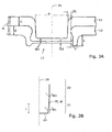
- Fig. 1 shown purely schematically. Shown are two metal workpieces 11 and 12 which have been joined together by a clinch connection 13. A portion of the punch tool 20, referred to herein as a punch, is shown above the clinching joint 10 or clinching point 10.
- the clinching tool 20 comprises a punch and a counter-tool 30, which may be formed as a die or as an anvil.
- the stamp is designed rotationally symmetrical with respect to its axis of rotation 24.
- the punch has a flank 25, which is arranged concentrically to the axis of rotation 24, with flank angle W.
- a flank 25 with a flank angle W1 and an upper transition region 22 of the flank 25 with a flank angle W2 is distinguished at the flank 25 between a lower transition region 21 adjoining the front end surface 23.
- the two transition regions 21, 22 merge into one another. They can as in the embodiments according to Fig. 1 . 3B and 6A shown in one another in a discontinuous manner and have different flank angles W1, W2.
- the metal workpieces 11, 12 (eg two sheets of different or the same thickness t1 and t2) to be joined have been pressed by the punch into a groove or recess or cavity or deformation space 31 of the die 30, similar to stamping or swaging under plastic deformation. as in Fig. 2A - 2C shown.
- a clinch connection 13 is produced, which has a snap-button-like or upset-point-like or embossing point-like shape.
- the Clinehtagen 13 connects the metal workpieces 11, 12 form- and frictionally with each other, as in Fig. 1, Fig. 2C and Fig. 3A and Fig. 4 indicated schematically.
- FIGS. 2A-2C show in three stages the formation of the clinch 13 without cutting portion with a counter tool 30 which is designed as a rigid die, this die has a recess or cavity or Kuhle (31) in the region of the processing surface.
- the stamp deforms the metal workpieces 11, 12 arranged on the working surface in an overlapping area or overlapping area above the recess or cavity or deformation space or cooling chamber 31 in such a way that the materials flow into the recess or cavity or through radial flow Deformation chamber or cowl 31, a local undercut f is formed.
- a first step according to Fig. 2A It will be appreciated that the first metal workpiece 11 and the second metal workpiece 12 are juxtaposed (ie, positioned one on top of the other).
- Fig. 2B is shown as the punch of the punch tool 20 is delivered and has already been partially sunk into the workpieces 11 and 12.
- the workpieces 11 and 12 deform under the high pressure of the punch and the material "flows" into the recess or cavity or deformation space or cage 31 of the die 30.
- the countersinking or pressing in of the punch takes place until the bottom 14 of the second metal workpiece 12 abuts as far as possible against the bottom of the recess or cavity or deformation space or Kuhle 31 of the die 30.
- the stamp is then pulled out (this step corresponds essentially to the one in FIG Fig. 1 shown situation).
- a scraper or hold-down 40 is used during the separation, which involves the separation of the punch facilitated after the deformation of the metal workpieces 11 and 12.
- a scraper or hold-down 40 is particularly advantageous if the stamp should clamp in the clinch 13 due to the forces and deformations occurring during forming.
- the scraper 40 is supported (quasi) against the surface 15 of the upper punch-side metal workpiece 11, while the stamp is withdrawn or withdrawn.
- the metal workpieces 11 and 12 to be joined by a hold-down is indicated by the number 41 or 40, pressed against or against the die 30.
- the stamping tool 20 comprises a printing cylinder (eg a hydraulic cylinder, compressed gas cylinder, pneumohydraulic cylinder, servaelectric cylinder) which effects the so-called stamp advance in the direction of the metal workpieces 11 and subsequently 12.
- a printing cylinder eg a hydraulic cylinder, compressed gas cylinder, pneumohydraulic cylinder, servaelectric cylinder
- the stamp is delivered ( Fig. 2A )
- the Einsenkphase takes place in which the stamp is sunk into the metal workpieces 11, 12 and these are compressed and deformed ( FIGS. 2B and 2C ).
- a phase called the stamp return stroke takes place (see Fig. 1 ).
- a clinch connection 13 and the workpieces 11, 12 can additionally be characterized by the following information: inner diameter of the joining element or stamping die, supernatant height h, residual floor thickness tb2 of the die-side metal workpiece 12, residual floor thickness tb1 of the stamp-side metal workpiece 11, die-side metal workpiece thickness t2, die-side metal workpiece thickness t1, and total workpiece thickness tt.
- a typical value for the undercut f is 0.5mm and a typical value for the neck thickness tn is 1.5mm.
- W 5 °, ie D1 ⁇ D2.
- FIGS. 4A to 4C Some aspects of the various investigations are in the FIGS. 4A to 4C shown because they apply analogously for stamp according to the invention. Shown is the flow behavior of the workpieces 11, 12 when using punches with different diameters. In Fig. 4A It is shown how the two metal workpieces 11, 12 deform when the punch has a diameter of 12mm. In Fig. 4B It is shown how the two metal workpieces 11, 12 deform when the punch has a diameter of 14mm. Fig. 4C shows how the two metal workpieces 11, 12 deform when the punch has a diameter of 20mm. In all three figures, a snapshot is shown before the Stempelschhub begins.
- FIGS. 4A to 4C recognize that the diameter D2 of the punch has an influence on the transverse flow of the materials or metal workpieces.
- the material of the metal workpiece 12 does not flow completely into the cavity formed by the recess or deformation space or groove 31, as can be seen in the region indicated by Y.
- the result is a good "filling" of the recess or cavity or deformation space or cooling chamber 31. If a punch with a diameter of 20 mm is used, a cavity (in FIG Fig. 4C denoted by X) between the workpieces 11 and 12.
- the punch diameter is only one of several parameters which have a direct influence on the clinching process and the strength of the clinch connection 13. It has shown that when clinching thicker workpieces with tt> 8mm, the design of the edge 25 plays a particularly important and important role.
- the present invention is characterized in that the punch, which is sunk into the metal workpieces 11 and 12 during the forming, is conically shaped.
- the conical shape of the punch extends at least over a part (referred to as transition regions 21, 22) of the length L of the punch, which is countersunk into the workpieces 11, 12 or, is pressed.
- the conical shape results from the fact that the edge 25 of the punch, see Fig. 3B is conically shaped at least in the lower transition region 21 to the Stirnend Chemistry 23 and has a flank angle W1, which is less than or equal to 10 degrees, preferably less than or equal to 5 degrees.
- the flank angle W2 of the upper transition region 22 is preferably equal to zero degrees or, more preferably, less than or equal to 5 degrees (embodiments according to FIGS Fig. 4A to 4c and 6B).
- stamps having a diameter D2 between 10 mm and 20 mm and having a flank angle W, W1, W2 which changes from a first angle W1 to a second angle W2 have proven particularly useful, the first angle W1 being less than or equal to 10 degrees and preferably smaller than or equal to is equal to 5 degrees and the second angle W2 is less than or equal to 2 degrees, and preferably 0 to 1 degrees.
- the first angle W1 is located in the immediate (lower) transition region 21 to the front end surface 23 (ie in the region of the workpiece end of the punch) and the second angle W2 on the (upper) transition region leading away from the metal workpiece 11, 12 and 22 (ie in the tool-side area of the punch).
- This embodiment of conical punches show a significantly lower tendency to jam and there are no (or weak) cavities X.
- the advantage of the lower radial stress and thus the lower tendency to jamming is due to the formation of the cavity X between the metal workpieces 11, 12 "bought", that is, the flank angle W, W1, W2 can not be chosen arbitrarily, otherwise the cavity X would be too large and the strength of the clinching would be too small.
- the conical shape of the stamp extends at least over the transition areas 21, 22 with that length L of the punch, which are sunk into the workpieces 11, 12.
- This length L for metal workpieces whose total workpiece thickness tt> 8mm can be determined as follows: 0.3tt ⁇ L ⁇ 2t. That is, the tapered transition regions 21, 22 correspond to between three-tenths of the total workpiece thickness tt and twice the total workpiece thickness tt.
- the achieved strengths, with the stamps according to the invention, for example with a punch with 12mm diameter and a 5 ° -0 ° -Stempelflanke (Embodiment 2, Fig. 6A ) are on average more than 50 kN or 55 kN. Under particularly carefully selected conditions, the tensile force is even around 58 kN and scatters only slightly by a few percent.
- a particularly advantageous clinching tool 20 has two similar punches which are arranged next to one another and the first metal workpiece 11 with the second metal workpiece 12 are able to connect through two clinch connections.
- two clinch connections are created side by side with a feed movement and a Einsenkterrorism simultaneously.
- the example of a corresponding DoppelclinchENS is in Fig. 5 shown.
- a thick steel profile carrier 11 first Motallwerk 1:1
- Blochprofilwinkel 12 second Metallwerk Glazel connected by two juxtaposed clinch connections 13 can be.
- the stripping force or stripping force must be greater than the clamping force of the punch. This word is, of course, strongly dependent on the stamp geometry used, as described, but also on the lubrication or coating of the tools. Maximum ejector forces from 30 kN to 40 kN have led to very reliable results. With an optimum design of the flank angle w or the taper of the punch, ejector forces of 25 kN are sufficient. For the 5 ° -0 ° punch (Embodiment 2, Fig. 6A ) even a further reduction of the ejector force can be considered, as it will never come to pinching the punch here.
- the scraper 40 simultaneously acts as a hold-down (41) and is dimensioned so that the metal workpieces 11, 12 undergo the least possible deformation to keep the delay of the workpieces 11, 12 as low as possible or free to keep.
- the corresponding stamp have or possess, particularly stable and stable components or assemblies or components manufacture the simplest, most effortless, cheapest and most reliable way.
- the cost of these components or assemblies or components with clinch connections 13 are below those of welded, riveted or bolted connections.
- the composite material costs for components or assemblies or components with clinch connections 13 are at zero. Furthermore, the working time is kept to a minimum or reduced or throttled.
- clinching connections 13 without a cutting portion can also be produced with an opening matrix.
- resiliently mounted lamellae of the die are pressed outward after the Finsenk process by the radial flow of the workpiece material below the punch and thus allows the formation of the undercut.
Landscapes
- Engineering & Computer Science (AREA)
- Mechanical Engineering (AREA)
- Shaping Metal By Deep-Drawing, Or The Like (AREA)
- Insertion Pins And Rivets (AREA)
- Portable Nailing Machines And Staplers (AREA)
- Perforating, Stamping-Out Or Severing By Means Other Than Cutting (AREA)
- Discharging, Photosensitive Material Shape In Electrophotography (AREA)
- Diaphragms For Electromechanical Transducers (AREA)
- Sheet Holders (AREA)
- Gripping Jigs, Holding Jigs, And Positioning Jigs (AREA)
- Bending Of Plates, Rods, And Pipes (AREA)
Priority Applications (2)
| Application Number | Priority Date | Filing Date | Title |
|---|---|---|---|
| EP08700550A EP2117746B1 (de) | 2007-02-13 | 2008-02-08 | Verfahren und werkzeug zum clinchen von dickblechen, sowie verwendung des werkzeugs |
| PL08700550T PL2117746T3 (pl) | 2007-02-13 | 2008-02-08 | Sposób i narzędzie do łączenia przez przetłaczanie grubych blach oraz stosowanie tego narzędzia |
Applications Claiming Priority (3)
| Application Number | Priority Date | Filing Date | Title |
|---|---|---|---|
| EP07102274 | 2007-02-13 | ||
| PCT/CH2008/000046 WO2008098389A1 (de) | 2007-02-13 | 2008-02-08 | Verfahren und werkzeug zum clinchen von dickblechen, sowie verwendung des werkzeugs |
| EP08700550A EP2117746B1 (de) | 2007-02-13 | 2008-02-08 | Verfahren und werkzeug zum clinchen von dickblechen, sowie verwendung des werkzeugs |
Publications (2)
| Publication Number | Publication Date |
|---|---|
| EP2117746A1 EP2117746A1 (de) | 2009-11-18 |
| EP2117746B1 true EP2117746B1 (de) | 2010-04-28 |
Family
ID=38198192
Family Applications (1)
| Application Number | Title | Priority Date | Filing Date |
|---|---|---|---|
| EP08700550A Not-in-force EP2117746B1 (de) | 2007-02-13 | 2008-02-08 | Verfahren und werkzeug zum clinchen von dickblechen, sowie verwendung des werkzeugs |
Country Status (22)
| Country | Link |
|---|---|
| US (1) | US9283612B2 (pl) |
| EP (1) | EP2117746B1 (pl) |
| JP (1) | JP5249951B2 (pl) |
| KR (1) | KR20090108693A (pl) |
| CN (1) | CN101610859B (pl) |
| AT (1) | ATE465829T1 (pl) |
| AU (1) | AU2008215090B2 (pl) |
| BR (1) | BRPI0807454A2 (pl) |
| CA (1) | CA2675307C (pl) |
| DE (1) | DE502008000600D1 (pl) |
| DK (1) | DK2117746T3 (pl) |
| ES (1) | ES2345304T3 (pl) |
| IL (1) | IL199719A (pl) |
| MX (1) | MX2009007789A (pl) |
| MY (1) | MY150171A (pl) |
| NZ (1) | NZ578770A (pl) |
| PL (1) | PL2117746T3 (pl) |
| RU (1) | RU2464118C2 (pl) |
| TW (1) | TWI454323B (pl) |
| UA (1) | UA99607C2 (pl) |
| WO (1) | WO2008098389A1 (pl) |
| ZA (1) | ZA200904683B (pl) |
Families Citing this family (35)
| Publication number | Priority date | Publication date | Assignee | Title |
|---|---|---|---|---|
| CN101934339B (zh) * | 2010-09-21 | 2012-10-17 | 上海交通大学 | 环形电致塑性无铆钉铆接装置 |
| DE202011000731U1 (de) * | 2011-03-30 | 2011-06-01 | Schmitz Cargobull AG, 48341 | Profilträger für ein Fahrzeugchassis und Nutzfahrzeugchassis mit einem solchen Profilträger |
| DE102011122037A1 (de) * | 2011-12-22 | 2013-06-27 | Kathrein-Werke Kg | Verfahren zur Herstellung einer elektrischen Hochfrequenz-Verbindung zwischen zwei Plattenabschnitten sowie eine zugehörige elektrische Hochfrequenz-Verbindung |
| JP2013139048A (ja) * | 2012-01-05 | 2013-07-18 | Tokyo Institute Of Technology | 被接合材の接合方法 |
| CN102601248A (zh) * | 2012-03-16 | 2012-07-25 | 金德精密配件(苏州)有限公司 | 一种金属板材铆接方法 |
| DE102012108161B4 (de) * | 2012-09-03 | 2016-09-22 | Bwg Bergwerk- Und Walzwerk-Maschinenbau Gmbh | Verfahren und Vorrichtung zum Verbinden von Metallbändern |
| CN103056235A (zh) * | 2012-12-31 | 2013-04-24 | 张家港固耐特围栏系统有限公司 | 一种用于围栏上的板材连接模具 |
| KR101323221B1 (ko) * | 2013-04-23 | 2013-10-30 | 김강민 | 무용접 접합 케이블 트레이 제작방법 |
| DE102013210370A1 (de) * | 2013-06-04 | 2014-12-04 | Böllhoff Verbindungstechnik GmbH | Einstellhilfe für eine Fügeeinrichtung mit einem Stempel und einem Gegenwerkzeug sowie ein Verfahren zum Einstellen der Fügeeinrichtung |
| KR101335612B1 (ko) * | 2013-07-17 | 2013-12-02 | 김강민 | 케이블 트레이 설치방법 |
| EP2832471B1 (de) * | 2013-08-02 | 2016-02-03 | MAGNA STEYR Engineering AG & Co KG | Verfahren zur Herstellung einer Stanzniet-Verbindung und Bauteilverbund |
| DE102013216820A1 (de) * | 2013-08-23 | 2015-02-26 | Volkswagen Aktiengesellschaft | Verfahren zum Verbinden von zumindest zwei Blechteilen |
| KR101407059B1 (ko) * | 2013-09-26 | 2014-06-12 | 김강민 | 케이블 트레이구조 |
| US10328481B2 (en) | 2014-03-18 | 2019-06-25 | Btm Company Llc | Clinching punch and apparatus |
| CN104438889B (zh) * | 2014-10-24 | 2017-01-18 | 安徽启光能源科技研究院有限公司 | 一种无铆钉铆接设备的自动脱铆器及其脱铆方法 |
| CN105478646B (zh) * | 2015-11-20 | 2017-11-03 | 西安交通大学 | 一种使用硬质铆柱一步法铆压的板材连接方法 |
| ITUB20160504A1 (it) * | 2016-01-15 | 2017-07-15 | System Spa | Compensatore di formato per un dispositivo di pressatura |
| CN107363178A (zh) * | 2016-05-12 | 2017-11-21 | 中兴通讯股份有限公司 | 一种铆合设备及其使用方法 |
| JP6607837B2 (ja) * | 2016-10-06 | 2019-11-20 | 三菱重工業株式会社 | 遮熱コーティング膜、タービン部材及び遮熱コーティング方法 |
| DE202017104046U1 (de) * | 2017-02-23 | 2017-07-27 | Ebm-Papst Landshut Gmbh | Verbindungseinheit für ein Gebläse |
| DE102017116560A1 (de) * | 2017-07-21 | 2019-01-24 | Tox Pressotechnik Gmbh & Co. Kg | Vorrichtung zum Fügen eines Werkstücks |
| JP7000827B2 (ja) * | 2017-12-08 | 2022-01-19 | トヨタ自動車株式会社 | 接合構造 |
| KR102018959B1 (ko) | 2017-12-15 | 2019-09-06 | 서진산업 주식회사 | 2단 압입 구조를 갖는 클린칭 장치 및 그 클린칭 장치를 이용한 접합방법 |
| KR102018958B1 (ko) | 2017-12-15 | 2019-09-06 | 서진산업 주식회사 | 이종소재 박판을 접합하기 위한 슬라이딩 클린칭 장치 및 그 클린칭 장치를 이용한 이종소재 박판 접합방법 |
| JP7035695B2 (ja) * | 2018-03-26 | 2022-03-15 | トヨタ自動車株式会社 | 接合装置および接合体の製造方法 |
| US11136811B2 (en) * | 2018-04-20 | 2021-10-05 | Magna Closures Inc. | Connection mechanism for thin wall tube |
| JP7182989B2 (ja) * | 2018-10-12 | 2022-12-05 | 株式会社アーレスティ | 接合体の製造方法および板状部材の品質管理方法 |
| CN109248964A (zh) * | 2018-10-30 | 2019-01-22 | 福州大学 | 一种无铆钉连接装置及其工作方法 |
| DE202018107289U1 (de) * | 2018-12-19 | 2020-03-23 | Reinz-Dichtungs-Gmbh | Plattenartiger Fluidbehälter |
| NL1043110B1 (en) * | 2018-12-24 | 2020-07-21 | Bosch Gmbh Robert | Process for manufacturing a laminate of stacked metal parts including a multi-layer blanking process step |
| CN109664084B (zh) * | 2019-01-31 | 2023-06-20 | 桂林电子科技大学 | 一种用于板材连接的滚压装置及其使用方法 |
| DE102019134024A1 (de) * | 2019-12-11 | 2021-06-17 | Eckold Gmbh & Co. Kg | Verfahren zum Fügen zweier Bleche mit einer variablen Gesamtdicke |
| CN111531045B (zh) * | 2020-04-06 | 2022-03-22 | 慈溪市汉德电器有限公司 | 一种金属件铆接工艺 |
| DE102020210839B4 (de) * | 2020-08-27 | 2023-03-23 | Arnold Umformtechnik Gmbh & Co. Kg | Vorrichtung und Verfahren zum Einsetzen eines Hilfsfügeteils in ein Werkstück und Anordnung |
| EP4574296B1 (en) * | 2023-12-19 | 2025-11-19 | Politechnika Wroclawska | An arrangement of tools for the forming of spot joints and a method of the forming of clinched spot joints with better strength parameters |
Family Cites Families (36)
| Publication number | Priority date | Publication date | Assignee | Title |
|---|---|---|---|---|
| US3555831A (en) * | 1968-09-16 | 1971-01-19 | Texaco Inc | Composite foundation member and method |
| US5435049A (en) * | 1980-09-08 | 1995-07-25 | Btm Corporation | Apparatus for joining sheet material |
| US5267383A (en) * | 1980-09-08 | 1993-12-07 | Btm Corporation | Apparatus for joining sheet material |
| EP0155619B1 (de) * | 1984-03-22 | 1990-01-17 | Gerd-Jürgen Eckold | Durchsetzfügeverfahren |
| DE3679364D1 (de) * | 1985-09-14 | 1991-06-27 | Eugen Rapp | Verfahren und vorrichtung zum verbinden duenner platten. |
| US4803767A (en) * | 1986-08-29 | 1989-02-14 | Lamb Robo | Clinching tool |
| DE3710929A1 (de) * | 1987-04-01 | 1988-10-13 | Eugen Rapp | Verfahren und vorrichtung zum verbinden aufeinanderliegender duenner platten |
| DE8803773U1 (de) * | 1988-03-19 | 1988-06-01 | Walter Eckold GmbH & Co KG Vorrichtungs- und Gerätebau, 3424 St Andreasberg | Zur Verwendung mit einer Presse bestimmter Werkzeugsatz zum Verbinden mehrerer flächig übereinanderliegender Bleche mittels lokalem Fließverpressen |
| DE3836937A1 (de) * | 1988-10-29 | 1990-05-03 | Eckold Vorrichtung | Durchsetzfuegevorrichtung |
| US5528815A (en) * | 1990-04-03 | 1996-06-25 | Webb; Edward L. T. | Clinching tool for sheet metal joining |
| US5305517A (en) * | 1991-09-23 | 1994-04-26 | Schleicher Louis C | Apparatus for forming clinch joints |
| DE9114122U1 (de) * | 1991-11-13 | 1993-04-01 | Eckold GmbH & Co KG, 3424 St. Andreasberg | Vorrichtung zum Fügen von Blechteilen |
| US5230136A (en) * | 1992-05-04 | 1993-07-27 | Savair Inc. | Punch and die set for sheet metal clinching |
| US5432989A (en) * | 1992-10-27 | 1995-07-18 | Archer Manufacturing Corporation | Apparatus and method for joining sheet material |
| SE9301097D0 (sv) * | 1993-03-31 | 1993-03-31 | Attexor Equipements Sa | A method for joining together two or several overlaying sheet formed members, an apparatus for carrying out said method and a joint resulting from said method |
| US5984563A (en) * | 1994-07-22 | 1999-11-16 | Btm Corporation | Apparatus for joining sheet material and joint formed therein |
| JP2780967B2 (ja) * | 1996-08-29 | 1998-07-30 | ナショナル住宅産業株式会社 | ワークの結合装置 |
| US5782130A (en) * | 1997-01-27 | 1998-07-21 | Btm Corporation | Apparatus for retaining tools |
| DE19913695A1 (de) * | 1998-03-25 | 2000-01-20 | Tox Pressotechnik Gmbh | Verfahren, Werkzeug und Stempel zum Verbinden von Bauteilen mit einer Platte |
| DE19843834C2 (de) * | 1998-09-24 | 2001-05-03 | Rudolf Mueller | Fügevorrichtung und Durchsetzfügeverfahren |
| US6217115B1 (en) * | 1999-04-20 | 2001-04-17 | Dura Global Technologies, Inc. | Simplified linkage assembly |
| WO2001058617A1 (en) * | 2000-02-09 | 2001-08-16 | Stresswave, Inc. | Method and apparatus for manufacturing structures with improved fatigue life |
| ATE364796T1 (de) * | 2000-06-08 | 2007-07-15 | Adval Tech Holding Ag | Hohlnietverbindung zwischen zwei blechen und verfahren zu ihrer herstellung |
| DE10031073B4 (de) * | 2000-06-30 | 2016-11-24 | Gustav Klauke Gmbh | Verfahren zum Vernieten |
| DE20106207U1 (de) * | 2001-04-09 | 2001-06-21 | Böllhoff GmbH, 33649 Bielefeld | Antriebseinrichtung für ein Einpresswerkzeug |
| DE10245604A1 (de) * | 2002-09-30 | 2004-04-15 | Fraunhofer-Gesellschaft zur Förderung der angewandten Forschung e.V. | Verfahren und Vorrichtung zum dauerhaften Verbinden von einander überlappenden, plattenförmigen Bauteilen |
| US6814531B2 (en) * | 2002-11-18 | 2004-11-09 | General Motors Corporation | Rotation restraining self-piercing rivet |
| JP4465581B2 (ja) * | 2002-11-29 | 2010-05-19 | 日立オートモティブシステムズ株式会社 | 重合板、重合管および重合管の張出かしめ方法、工具 |
| JP4306507B2 (ja) * | 2004-03-26 | 2009-08-05 | 日産自動車株式会社 | 板材のかしめ接合方法、および板材のかしめ接合装置 |
| AU2004324570A1 (en) * | 2004-11-08 | 2006-05-11 | Falconbridge Limited | Clinching tool, die and method for use thereof |
| US20060096075A1 (en) * | 2004-11-08 | 2006-05-11 | Victor Robinson | Clinching tool, die and method for use thereof |
| DE102005000023A1 (de) * | 2005-03-22 | 2006-09-28 | Hilti Ag | Durchzuganordnung und Verfahren dazu |
| JP5007872B2 (ja) * | 2005-03-24 | 2012-08-22 | 日立オートモティブシステムズ株式会社 | 単筒式油圧緩衝器および単筒式油圧緩衝器におけるブラケットの取付方法 |
| CN2838800Y (zh) * | 2005-11-09 | 2006-11-22 | 青岛港(集团)有限公司 | 护套上口翻铆器 |
| JP4920040B2 (ja) * | 2006-07-31 | 2012-04-18 | トヨタ自動車株式会社 | 組部材と組部材の製造方法 |
| DE102008003463A1 (de) * | 2008-01-08 | 2009-07-09 | Trw Automotive Gmbh | Verfahren zur Herstellung einer Lagerschalenbaugruppe, sowie Lagerschalenbaugruppe für ein Kugelgelenk |
-
2008
- 2008-02-08 DE DE502008000600T patent/DE502008000600D1/de active Active
- 2008-02-08 PL PL08700550T patent/PL2117746T3/pl unknown
- 2008-02-08 UA UAA200908504A patent/UA99607C2/ru unknown
- 2008-02-08 CA CA2675307A patent/CA2675307C/en not_active Expired - Fee Related
- 2008-02-08 MY MYPI20092944A patent/MY150171A/en unknown
- 2008-02-08 EP EP08700550A patent/EP2117746B1/de not_active Not-in-force
- 2008-02-08 ES ES08700550T patent/ES2345304T3/es active Active
- 2008-02-08 NZ NZ578770A patent/NZ578770A/en unknown
- 2008-02-08 DK DK08700550.0T patent/DK2117746T3/da active
- 2008-02-08 AU AU2008215090A patent/AU2008215090B2/en not_active Ceased
- 2008-02-08 BR BRPI0807454-2A2A patent/BRPI0807454A2/pt not_active Application Discontinuation
- 2008-02-08 MX MX2009007789A patent/MX2009007789A/es active IP Right Grant
- 2008-02-08 CN CN2008800047937A patent/CN101610859B/zh not_active Expired - Fee Related
- 2008-02-08 KR KR1020097014758A patent/KR20090108693A/ko not_active Ceased
- 2008-02-08 AT AT08700550T patent/ATE465829T1/de active
- 2008-02-08 WO PCT/CH2008/000046 patent/WO2008098389A1/de not_active Ceased
- 2008-02-08 ZA ZA200904683A patent/ZA200904683B/xx unknown
- 2008-02-08 RU RU2009134105/02A patent/RU2464118C2/ru not_active IP Right Cessation
- 2008-02-08 JP JP2009549354A patent/JP5249951B2/ja not_active Expired - Fee Related
- 2008-02-13 TW TW097105002A patent/TWI454323B/zh not_active IP Right Cessation
-
2009
- 2009-07-07 IL IL199719A patent/IL199719A/en not_active IP Right Cessation
- 2009-08-12 US US12/539,903 patent/US9283612B2/en not_active Expired - Fee Related
Also Published As
| Publication number | Publication date |
|---|---|
| US9283612B2 (en) | 2016-03-15 |
| UA99607C2 (ru) | 2012-09-10 |
| CA2675307C (en) | 2015-05-05 |
| HK1137962A1 (zh) | 2010-08-13 |
| ZA200904683B (en) | 2010-09-29 |
| MY150171A (en) | 2013-12-13 |
| US20100018278A1 (en) | 2010-01-28 |
| AU2008215090A1 (en) | 2008-08-21 |
| RU2464118C2 (ru) | 2012-10-20 |
| RU2009134105A (ru) | 2011-03-20 |
| BRPI0807454A2 (pt) | 2014-05-20 |
| CN101610859A (zh) | 2009-12-23 |
| DE502008000600D1 (de) | 2010-06-10 |
| CN101610859B (zh) | 2013-07-17 |
| JP2010517786A (ja) | 2010-05-27 |
| DK2117746T3 (da) | 2010-08-16 |
| ATE465829T1 (de) | 2010-05-15 |
| WO2008098389A1 (de) | 2008-08-21 |
| TWI454323B (zh) | 2014-10-01 |
| EP2117746A1 (de) | 2009-11-18 |
| PL2117746T3 (pl) | 2010-10-29 |
| IL199719A0 (en) | 2010-04-15 |
| TW200916221A (en) | 2009-04-16 |
| MX2009007789A (es) | 2009-07-31 |
| KR20090108693A (ko) | 2009-10-16 |
| CA2675307A1 (en) | 2008-08-21 |
| ES2345304T3 (es) | 2010-09-20 |
| IL199719A (en) | 2013-05-30 |
| NZ578770A (en) | 2012-06-29 |
| JP5249951B2 (ja) | 2013-07-31 |
| AU2008215090B2 (en) | 2013-01-10 |
Similar Documents
| Publication | Publication Date | Title |
|---|---|---|
| EP2117746B1 (de) | Verfahren und werkzeug zum clinchen von dickblechen, sowie verwendung des werkzeugs | |
| EP2117747B1 (de) | Verfahren zum clinchen von dicken metallwerkstücken und verwendung eines clinchwerkzeugs | |
| EP1198309B1 (de) | Verfahren, vorrichtung sowie hilfsfügeteil zum mechanischen fügen | |
| EP2084033B1 (de) | Strukturelement für fahrzeugsitz | |
| EP3505270B1 (de) | Setzeinheit für eine stanznietvorrichtung, stanznietvorrichtung und verfahren zum herstellen einer solchen | |
| EP1442809B1 (de) | Verfahren zur Herstellung von Hohlkörperelementen | |
| DE4404659C5 (de) | Verfahren zum Herstellen einer Nietverbindung sowie Werkzeug zur Durchführung des Verfahrens | |
| EP1115518B1 (de) | Verfahren und vorrichtung zum verbinden von sich überlappenden plattenförmigen bauteilen | |
| DE10213793A1 (de) | Verfahren, Vorrichtung und Hilfsfügeteil zum Fügen von mindestens zwei Bauteilen | |
| DE102005031916B4 (de) | Halbhohlstanzniet zum mechanischen Fügen und Verfahren zum Herstellen einer Fügeverbindung | |
| DE10124920A1 (de) | Verfahren zum Verbinden von Teilen mit Verbindungselementen | |
| DE102005037914B3 (de) | Verfahren zum Setzen von Stanznieten | |
| DE19945743A1 (de) | Verfahren und Vorrichtung zum Verbinden von sich überlappenden plattenförmigen Bauteilen | |
| DE19927101A1 (de) | Verfahren und Vorrichtung zum Clinchen | |
| DE102017205940A1 (de) | Verfahren zur Herstellung eines Bauteilverbunds und Kraftfahrzeug | |
| DE10102712B4 (de) | Verfahren zum Verbinden von zumindest teilweise überlappenden Bauteilen und Vorrichtung hierfür | |
| DE19913757A1 (de) | Verfahren zur Herstellung einer Nietverbindung | |
| DE102008062850B4 (de) | Verfahren zur Herstellung eines Tiefziehteils sowie ein Verfahren zur Steuerung einer Tiefziehvorrichtung und eine Tiefziehvorrichtung | |
| DE102015008171A1 (de) | Vorrichtung und Verfahren zum Bearbeiten eines Blechbauteils | |
| DE19643076C2 (de) | Vorrichtung zum in einem Arbeitsgang erfolgenden Stanzen und Fügen mindestens zweier Blechteile | |
| DE69216395T2 (de) | Verfahren zum nieten und vorrichtung zur durchführung des verfahrens | |
| DE10151659B4 (de) | Verfahren zum Fügen von zumindest zwei Bauteilen und Vorrichtung hierfür | |
| DE102015000982A1 (de) | Verfahren zum Verbinden von mehreren flachen Bauteilen | |
| DE10323740B4 (de) | Baugruppe, mit einem Stanzniet und mindestens zwei zu verbindenden Bauteilen | |
| DE102007050069B3 (de) | Verfahren zur Herstellung einer Stanznietverbindung |
Legal Events
| Date | Code | Title | Description |
|---|---|---|---|
| PUAI | Public reference made under article 153(3) epc to a published international application that has entered the european phase |
Free format text: ORIGINAL CODE: 0009012 |
|
| 17P | Request for examination filed |
Effective date: 20090831 |
|
| AK | Designated contracting states |
Kind code of ref document: A1 Designated state(s): AT BE BG CH CY CZ DE DK EE ES FI FR GB GR HR HU IE IS IT LI LT LU LV MC MT NL NO PL PT RO SE SI SK TR |
|
| GRAP | Despatch of communication of intention to grant a patent |
Free format text: ORIGINAL CODE: EPIDOSNIGR1 |
|
| GRAS | Grant fee paid |
Free format text: ORIGINAL CODE: EPIDOSNIGR3 |
|
| GRAA | (expected) grant |
Free format text: ORIGINAL CODE: 0009210 |
|
| AK | Designated contracting states |
Kind code of ref document: B1 Designated state(s): AT BE BG CH CY CZ DE DK EE ES FI FR GB GR HR HU IE IS IT LI LT LU LV MC MT NL NO PL PT RO SE SI SK TR |
|
| REG | Reference to a national code |
Ref country code: GB Ref legal event code: FG4D Free format text: NOT ENGLISH |
|
| REG | Reference to a national code |
Ref country code: CH Ref legal event code: EP |
|
| REG | Reference to a national code |
Ref country code: IE Ref legal event code: FG4D Free format text: LANGUAGE OF EP DOCUMENT: GERMAN |
|
| REF | Corresponds to: |
Ref document number: 502008000600 Country of ref document: DE Date of ref document: 20100610 Kind code of ref document: P |
|
| REG | Reference to a national code |
Ref country code: NL Ref legal event code: T3 |
|
| REG | Reference to a national code |
Ref country code: SE Ref legal event code: TRGR |
|
| REG | Reference to a national code |
Ref country code: GR Ref legal event code: EP Ref document number: 20100401497 Country of ref document: GR |
|
| REG | Reference to a national code |
Ref country code: HK Ref legal event code: DE Ref document number: 1137962 Country of ref document: HK |
|
| REG | Reference to a national code |
Ref country code: DK Ref legal event code: T3 |
|
| REG | Reference to a national code |
Ref country code: ES Ref legal event code: FG2A Ref document number: 2345304 Country of ref document: ES Kind code of ref document: T3 |
|
| LTIE | Lt: invalidation of european patent or patent extension |
Effective date: 20100428 |
|
| REG | Reference to a national code |
Ref country code: NO Ref legal event code: T2 Effective date: 20100428 |
|
| REG | Reference to a national code |
Ref country code: SK Ref legal event code: T3 Ref document number: E 7531 Country of ref document: SK |
|
| PG25 | Lapsed in a contracting state [announced via postgrant information from national office to epo] |
Ref country code: LT Free format text: LAPSE BECAUSE OF FAILURE TO SUBMIT A TRANSLATION OF THE DESCRIPTION OR TO PAY THE FEE WITHIN THE PRESCRIBED TIME-LIMIT Effective date: 20100428 |
|
| REG | Reference to a national code |
Ref country code: PL Ref legal event code: T3 |
|
| REG | Reference to a national code |
Ref country code: HK Ref legal event code: GR Ref document number: 1137962 Country of ref document: HK |
|
| PG25 | Lapsed in a contracting state [announced via postgrant information from national office to epo] |
Ref country code: HR Free format text: LAPSE BECAUSE OF FAILURE TO SUBMIT A TRANSLATION OF THE DESCRIPTION OR TO PAY THE FEE WITHIN THE PRESCRIBED TIME-LIMIT Effective date: 20100428 Ref country code: LV Free format text: LAPSE BECAUSE OF FAILURE TO SUBMIT A TRANSLATION OF THE DESCRIPTION OR TO PAY THE FEE WITHIN THE PRESCRIBED TIME-LIMIT Effective date: 20100428 Ref country code: IS Free format text: LAPSE BECAUSE OF FAILURE TO SUBMIT A TRANSLATION OF THE DESCRIPTION OR TO PAY THE FEE WITHIN THE PRESCRIBED TIME-LIMIT Effective date: 20100828 Ref country code: SI Free format text: LAPSE BECAUSE OF FAILURE TO SUBMIT A TRANSLATION OF THE DESCRIPTION OR TO PAY THE FEE WITHIN THE PRESCRIBED TIME-LIMIT Effective date: 20100428 |
|
| PG25 | Lapsed in a contracting state [announced via postgrant information from national office to epo] |
Ref country code: CY Free format text: LAPSE BECAUSE OF FAILURE TO SUBMIT A TRANSLATION OF THE DESCRIPTION OR TO PAY THE FEE WITHIN THE PRESCRIBED TIME-LIMIT Effective date: 20100616 |
|
| PG25 | Lapsed in a contracting state [announced via postgrant information from national office to epo] |
Ref country code: EE Free format text: LAPSE BECAUSE OF FAILURE TO SUBMIT A TRANSLATION OF THE DESCRIPTION OR TO PAY THE FEE WITHIN THE PRESCRIBED TIME-LIMIT Effective date: 20100428 |
|
| PG25 | Lapsed in a contracting state [announced via postgrant information from national office to epo] |
Ref country code: RO Free format text: LAPSE BECAUSE OF FAILURE TO SUBMIT A TRANSLATION OF THE DESCRIPTION OR TO PAY THE FEE WITHIN THE PRESCRIBED TIME-LIMIT Effective date: 20100428 |
|
| PLBE | No opposition filed within time limit |
Free format text: ORIGINAL CODE: 0009261 |
|
| 26N | No opposition filed |
Effective date: 20110131 |
|
| PLAA | Information modified related to event that no opposition was filed |
Free format text: ORIGINAL CODE: 0009299DELT |
|
| PLAA | Information modified related to event that no opposition was filed |
Free format text: ORIGINAL CODE: 0009299DELT |
|
| PLBE | No opposition filed within time limit |
Free format text: ORIGINAL CODE: 0009261 |
|
| STAA | Information on the status of an ep patent application or granted ep patent |
Free format text: STATUS: NO OPPOSITION FILED WITHIN TIME LIMIT |
|
| D26N | No opposition filed (deleted) | ||
| RIN2 | Information on inventor provided after grant (corrected) |
Inventor name: TROJER, ANDREAS Inventor name: ISRAEL, MARKUS Inventor name: ILLEDITS, THOMAS Inventor name: MATHEISL, MICHAEL Inventor name: NOVACEK, THOMAS Inventor name: MAUERMANN, REINHARD |
|
| PG25 | Lapsed in a contracting state [announced via postgrant information from national office to epo] |
Ref country code: MC Free format text: LAPSE BECAUSE OF NON-PAYMENT OF DUE FEES Effective date: 20110228 |
|
| PG25 | Lapsed in a contracting state [announced via postgrant information from national office to epo] |
Ref country code: MT Free format text: LAPSE BECAUSE OF FAILURE TO SUBMIT A TRANSLATION OF THE DESCRIPTION OR TO PAY THE FEE WITHIN THE PRESCRIBED TIME-LIMIT Effective date: 20100428 |
|
| REG | Reference to a national code |
Ref country code: SK Ref legal event code: TA4A Free format text: (72) TROJER ANDREAS, WIEN, AT; MATHEISL MICHAEL, V?SENDORF, AT; ILLEDITS THOMAS, NEUFELD, AT; NOVACEK THOMAS, SCHWECHAT, AT; ISRAEL MARKUS, DRESDEN, DE; MAUERMANN REINHARD, DRESDEN, DE; Effective date: 20111114 Ref country code: SK Ref legal event code: TC4A Ref document number: E 7531 Country of ref document: SK Owner name: MAUERMANN REINHARD, DRESDEN, DE Effective date: 20111114 Ref country code: SK Ref legal event code: TC4A Ref document number: E 7531 Country of ref document: SK Owner name: MATHEISL MICHAEL, VOESENDORF, AT Effective date: 20111114 Ref country code: SK Ref legal event code: TC4A Ref document number: E 7531 Country of ref document: SK Owner name: NOVACEK THOMAS, SCHWECHAT, AT Effective date: 20111114 Ref country code: SK Ref legal event code: TC4A Ref document number: E 7531 Country of ref document: SK Owner name: TROJER ANDREAS, WIEN, AT Effective date: 20111114 Ref country code: SK Ref legal event code: TC4A Ref document number: E 7531 Country of ref document: SK Owner name: ILLEDITS THOMAS, NEUFELD, AT Effective date: 20111114 Ref country code: SK Ref legal event code: TC4A Ref document number: E 7531 Country of ref document: SK Owner name: ISRAEL MARKUS, DRESDEN, DE Effective date: 20111114 |
|
| PG25 | Lapsed in a contracting state [announced via postgrant information from national office to epo] |
Ref country code: PT Free format text: LAPSE BECAUSE OF NON-PAYMENT OF DUE FEES Effective date: 20100428 |
|
| PG25 | Lapsed in a contracting state [announced via postgrant information from national office to epo] |
Ref country code: BG Free format text: LAPSE BECAUSE OF FAILURE TO SUBMIT A TRANSLATION OF THE DESCRIPTION OR TO PAY THE FEE WITHIN THE PRESCRIBED TIME-LIMIT Effective date: 20100728 |
|
| PG25 | Lapsed in a contracting state [announced via postgrant information from national office to epo] |
Ref country code: HU Free format text: LAPSE BECAUSE OF FAILURE TO SUBMIT A TRANSLATION OF THE DESCRIPTION OR TO PAY THE FEE WITHIN THE PRESCRIBED TIME-LIMIT Effective date: 20100428 |
|
| REG | Reference to a national code |
Ref country code: FR Ref legal event code: PLFP Year of fee payment: 9 |
|
| REG | Reference to a national code |
Ref country code: FR Ref legal event code: PLFP Year of fee payment: 10 |
|
| REG | Reference to a national code |
Ref country code: FR Ref legal event code: PLFP Year of fee payment: 11 |
|
| PGFP | Annual fee paid to national office [announced via postgrant information from national office to epo] |
Ref country code: LU Payment date: 20180216 Year of fee payment: 11 Ref country code: NL Payment date: 20180216 Year of fee payment: 11 |
|
| PGFP | Annual fee paid to national office [announced via postgrant information from national office to epo] |
Ref country code: CZ Payment date: 20180207 Year of fee payment: 11 Ref country code: FI Payment date: 20180219 Year of fee payment: 11 Ref country code: NO Payment date: 20180226 Year of fee payment: 11 Ref country code: CH Payment date: 20180216 Year of fee payment: 11 Ref country code: GB Payment date: 20180216 Year of fee payment: 11 Ref country code: ES Payment date: 20180327 Year of fee payment: 11 Ref country code: DK Payment date: 20180216 Year of fee payment: 11 |
|
| PGFP | Annual fee paid to national office [announced via postgrant information from national office to epo] |
Ref country code: SK Payment date: 20180206 Year of fee payment: 11 Ref country code: IE Payment date: 20180219 Year of fee payment: 11 Ref country code: SE Payment date: 20180227 Year of fee payment: 11 Ref country code: IT Payment date: 20180227 Year of fee payment: 11 Ref country code: BE Payment date: 20180216 Year of fee payment: 11 Ref country code: PL Payment date: 20180206 Year of fee payment: 11 Ref country code: GR Payment date: 20180213 Year of fee payment: 11 Ref country code: TR Payment date: 20180205 Year of fee payment: 11 Ref country code: AT Payment date: 20180219 Year of fee payment: 11 |
|
| REG | Reference to a national code |
Ref country code: DK Ref legal event code: EBP Effective date: 20190228 Ref country code: NO Ref legal event code: MMEP |
|
| REG | Reference to a national code |
Ref country code: CH Ref legal event code: PL |
|
| REG | Reference to a national code |
Ref country code: SE Ref legal event code: EUG |
|
| REG | Reference to a national code |
Ref country code: NL Ref legal event code: MM Effective date: 20190301 |
|
| REG | Reference to a national code |
Ref country code: AT Ref legal event code: MM01 Ref document number: 465829 Country of ref document: AT Kind code of ref document: T Effective date: 20190208 |
|
| GBPC | Gb: european patent ceased through non-payment of renewal fee |
Effective date: 20190208 |
|
| PG25 | Lapsed in a contracting state [announced via postgrant information from national office to epo] |
Ref country code: SE Free format text: LAPSE BECAUSE OF NON-PAYMENT OF DUE FEES Effective date: 20190209 Ref country code: CZ Free format text: LAPSE BECAUSE OF NON-PAYMENT OF DUE FEES Effective date: 20190208 Ref country code: LU Free format text: LAPSE BECAUSE OF NON-PAYMENT OF DUE FEES Effective date: 20190208 Ref country code: SK Free format text: LAPSE BECAUSE OF NON-PAYMENT OF DUE FEES Effective date: 20190208 Ref country code: FI Free format text: LAPSE BECAUSE OF NON-PAYMENT OF DUE FEES Effective date: 20190208 Ref country code: NO Free format text: LAPSE BECAUSE OF NON-PAYMENT OF DUE FEES Effective date: 20190228 |
|
| REG | Reference to a national code |
Ref country code: SK Ref legal event code: MM4A Ref document number: E 7531 Country of ref document: SK Effective date: 20190208 |
|
| REG | Reference to a national code |
Ref country code: BE Ref legal event code: MM Effective date: 20190228 |
|
| REG | Reference to a national code |
Ref country code: IE Ref legal event code: MM4A |
|
| PG25 | Lapsed in a contracting state [announced via postgrant information from national office to epo] |
Ref country code: GR Free format text: LAPSE BECAUSE OF NON-PAYMENT OF DUE FEES Effective date: 20190904 |
|
| PG25 | Lapsed in a contracting state [announced via postgrant information from national office to epo] |
Ref country code: CH Free format text: LAPSE BECAUSE OF NON-PAYMENT OF DUE FEES Effective date: 20190228 Ref country code: AT Free format text: LAPSE BECAUSE OF NON-PAYMENT OF DUE FEES Effective date: 20190208 Ref country code: LI Free format text: LAPSE BECAUSE OF NON-PAYMENT OF DUE FEES Effective date: 20190228 |
|
| PG25 | Lapsed in a contracting state [announced via postgrant information from national office to epo] |
Ref country code: IE Free format text: LAPSE BECAUSE OF NON-PAYMENT OF DUE FEES Effective date: 20190208 Ref country code: NL Free format text: LAPSE BECAUSE OF NON-PAYMENT OF DUE FEES Effective date: 20190301 Ref country code: DK Free format text: LAPSE BECAUSE OF NON-PAYMENT OF DUE FEES Effective date: 20190228 Ref country code: GB Free format text: LAPSE BECAUSE OF NON-PAYMENT OF DUE FEES Effective date: 20190208 |
|
| PG25 | Lapsed in a contracting state [announced via postgrant information from national office to epo] |
Ref country code: BE Free format text: LAPSE BECAUSE OF NON-PAYMENT OF DUE FEES Effective date: 20190228 Ref country code: IT Free format text: LAPSE BECAUSE OF NON-PAYMENT OF DUE FEES Effective date: 20190208 |
|
| REG | Reference to a national code |
Ref country code: ES Ref legal event code: FD2A Effective date: 20200330 |
|
| PG25 | Lapsed in a contracting state [announced via postgrant information from national office to epo] |
Ref country code: ES Free format text: LAPSE BECAUSE OF NON-PAYMENT OF DUE FEES Effective date: 20190209 |
|
| PGFP | Annual fee paid to national office [announced via postgrant information from national office to epo] |
Ref country code: FR Payment date: 20210223 Year of fee payment: 14 |
|
| PGFP | Annual fee paid to national office [announced via postgrant information from national office to epo] |
Ref country code: DE Payment date: 20210329 Year of fee payment: 14 |
|
| PG25 | Lapsed in a contracting state [announced via postgrant information from national office to epo] |
Ref country code: TR Free format text: LAPSE BECAUSE OF NON-PAYMENT OF DUE FEES Effective date: 20190208 |
|
| REG | Reference to a national code |
Ref country code: DE Ref legal event code: R119 Ref document number: 502008000600 Country of ref document: DE |
|
| PG25 | Lapsed in a contracting state [announced via postgrant information from national office to epo] |
Ref country code: FR Free format text: LAPSE BECAUSE OF NON-PAYMENT OF DUE FEES Effective date: 20220228 |
|
| PG25 | Lapsed in a contracting state [announced via postgrant information from national office to epo] |
Ref country code: DE Free format text: LAPSE BECAUSE OF NON-PAYMENT OF DUE FEES Effective date: 20220901 |
|
| PG25 | Lapsed in a contracting state [announced via postgrant information from national office to epo] |
Ref country code: PL Free format text: LAPSE BECAUSE OF NON-PAYMENT OF DUE FEES Effective date: 20190208 |