EP2117746B1 - Method and tool for clinching thick sheet metal, and use of the tool - Google Patents
Method and tool for clinching thick sheet metal, and use of the tool Download PDFInfo
- Publication number
- EP2117746B1 EP2117746B1 EP08700550A EP08700550A EP2117746B1 EP 2117746 B1 EP2117746 B1 EP 2117746B1 EP 08700550 A EP08700550 A EP 08700550A EP 08700550 A EP08700550 A EP 08700550A EP 2117746 B1 EP2117746 B1 EP 2117746B1
- Authority
- EP
- European Patent Office
- Prior art keywords
- tool
- die
- metal
- clinching
- metal workpiece
- Prior art date
- Legal status (The legal status is an assumption and is not a legal conclusion. Google has not performed a legal analysis and makes no representation as to the accuracy of the status listed.)
- Not-in-force
Links
Images


Classifications
-
- B—PERFORMING OPERATIONS; TRANSPORTING
- B21—MECHANICAL METAL-WORKING WITHOUT ESSENTIALLY REMOVING MATERIAL; PUNCHING METAL
- B21D—WORKING OR PROCESSING OF SHEET METAL OR METAL TUBES, RODS OR PROFILES WITHOUT ESSENTIALLY REMOVING MATERIAL; PUNCHING METAL
- B21D39/00—Application of procedures in order to connect objects or parts, e.g. coating with sheet metal otherwise than by plating; Tube expanders
- B21D39/03—Application of procedures in order to connect objects or parts, e.g. coating with sheet metal otherwise than by plating; Tube expanders of sheet metal otherwise than by folding
- B21D39/031—Joining superposed plates by locally deforming without slitting or piercing
-
- B—PERFORMING OPERATIONS; TRANSPORTING
- B23—MACHINE TOOLS; METAL-WORKING NOT OTHERWISE PROVIDED FOR
- B23P—METAL-WORKING NOT OTHERWISE PROVIDED FOR; COMBINED OPERATIONS; UNIVERSAL MACHINE TOOLS
- B23P11/00—Connecting or disconnecting metal parts or objects by metal-working techniques not otherwise provided for
-
- B—PERFORMING OPERATIONS; TRANSPORTING
- B23—MACHINE TOOLS; METAL-WORKING NOT OTHERWISE PROVIDED FOR
- B23P—METAL-WORKING NOT OTHERWISE PROVIDED FOR; COMBINED OPERATIONS; UNIVERSAL MACHINE TOOLS
- B23P19/00—Machines for simply fitting together or separating metal parts or objects, or metal and non-metal parts, whether or not involving some deformation; Tools or devices therefor so far as not provided for in other classes
- B23P19/02—Machines for simply fitting together or separating metal parts or objects, or metal and non-metal parts, whether or not involving some deformation; Tools or devices therefor so far as not provided for in other classes for connecting objects by press fit or for detaching same
-
- B—PERFORMING OPERATIONS; TRANSPORTING
- B25—HAND TOOLS; PORTABLE POWER-DRIVEN TOOLS; MANIPULATORS
- B25B—TOOLS OR BENCH DEVICES NOT OTHERWISE PROVIDED FOR, FOR FASTENING, CONNECTING, DISENGAGING OR HOLDING
- B25B27/00—Hand tools, specially adapted for fitting together or separating parts or objects whether or not involving some deformation, not otherwise provided for
- B25B27/02—Hand tools, specially adapted for fitting together or separating parts or objects whether or not involving some deformation, not otherwise provided for for connecting objects by press fit or detaching same
-
- Y—GENERAL TAGGING OF NEW TECHNOLOGICAL DEVELOPMENTS; GENERAL TAGGING OF CROSS-SECTIONAL TECHNOLOGIES SPANNING OVER SEVERAL SECTIONS OF THE IPC; TECHNICAL SUBJECTS COVERED BY FORMER USPC CROSS-REFERENCE ART COLLECTIONS [XRACs] AND DIGESTS
- Y10—TECHNICAL SUBJECTS COVERED BY FORMER USPC
- Y10T—TECHNICAL SUBJECTS COVERED BY FORMER US CLASSIFICATION
- Y10T29/00—Metal working
- Y10T29/49—Method of mechanical manufacture
- Y10T29/49826—Assembling or joining
- Y10T29/49908—Joining by deforming
Definitions
- the invention relates to a clinching tool for producing a load-bearing connection of two metal workpieces according to the preamble of claim 1, a method for clinching metal workpieces for producing a load-bearing connection according to the preamble of claim 9, and the use of the clinching tool according to the preamble of claim 14.
- Clinching is a reshaping process that has been known for some time. This method is also referred to as push-through joining.
- the clinching is a Umtormtechnische Mattsteehnologie, depending on the embodiment without auxiliary joining part.
- the object of the invention is to provide a method to clinch sheets and support of thick sheets, preferably with thicknesses greater than 4mm, with low clamping forces, to be worked with optimal Schutenauspragung and the greatest possible neck thickness to a correspondingly high To ensure strength of the clinch connection.
- a corresponding tool should be proposed and its use optimized.
- the inventive tools or apparatus are characterized in that they have a conically shaped punch with two transition regions, wherein the transition region in the region of the Stirnend vom has a greater angle than the adjoining upper Transition area.
- the larger flank angle may be less than or equal to 10 degrees and transition to a flank angle of 5 degrees to zero degrees.
- the diameter of this stamp is preferably in the range between 10mm and 35mm. Particularly preferred are diameters between 12mm (14mm, 16mm, 18mm) to 20mm or 25mm, this diameter depends on the thickness of the metal workpieces to be joined and on the required strength or tensile force.
- clinching becomes a real alternative for welding, which hitherto has mostly been used as a jointing method for joining thick sheets or workpieces (for example a St-37, St-44, St-52, St-70 sheet or EN-sheet).
- S235, S275, S355, S460 sheet metal) or carrier (thickness> 4 mm) is used.
- clinching can also replace rivet and screw connections.
- metal sheets, profiles and other metal parts or metal workpieces of different thicknesses and different materials can be connected to one another.
- the connection of two metal workpieces arises during clinching exclusively and directly from the material (s) of the metal workpieces to be joined.
- the elements connected by clinching are referred to herein as a clinched workpiece.
- the present invention makes it increasingly possible to use metal workpiece connections, for example steel connections or sheet metal profile connections or sheet metal connections or sheet metal strip connections or sheet metal connections, now also in elevator and escalator construction, wherein, inter alia, a part of the elevator car or of the elevator and / or the elevator machine room or the framework or structure of an escalator can be made by means of clinching technology.
- metal workpiece connections for example steel connections or sheet metal profile connections or sheet metal connections or sheet metal strip connections or sheet metal connections
- Fig. 1 shown purely schematically. Shown are two metal workpieces 11 and 12 which have been joined together by a clinch connection 13. A portion of the punch tool 20, referred to herein as a punch, is shown above the clinching joint 10 or clinching point 10.
- the clinching tool 20 comprises a punch and a counter-tool 30, which may be formed as a die or as an anvil.
- the stamp is designed rotationally symmetrical with respect to its axis of rotation 24.
- the punch has a flank 25, which is arranged concentrically to the axis of rotation 24, with flank angle W.
- a flank 25 with a flank angle W1 and an upper transition region 22 of the flank 25 with a flank angle W2 is distinguished at the flank 25 between a lower transition region 21 adjoining the front end surface 23.
- the two transition regions 21, 22 merge into one another. They can as in the embodiments according to Fig. 1 . 3B and 6A shown in one another in a discontinuous manner and have different flank angles W1, W2.
- the metal workpieces 11, 12 (eg two sheets of different or the same thickness t1 and t2) to be joined have been pressed by the punch into a groove or recess or cavity or deformation space 31 of the die 30, similar to stamping or swaging under plastic deformation. as in Fig. 2A - 2C shown.
- a clinch connection 13 is produced, which has a snap-button-like or upset-point-like or embossing point-like shape.
- the Clinehtagen 13 connects the metal workpieces 11, 12 form- and frictionally with each other, as in Fig. 1, Fig. 2C and Fig. 3A and Fig. 4 indicated schematically.
- FIGS. 2A-2C show in three stages the formation of the clinch 13 without cutting portion with a counter tool 30 which is designed as a rigid die, this die has a recess or cavity or Kuhle (31) in the region of the processing surface.
- the stamp deforms the metal workpieces 11, 12 arranged on the working surface in an overlapping area or overlapping area above the recess or cavity or deformation space or cooling chamber 31 in such a way that the materials flow into the recess or cavity or through radial flow Deformation chamber or cowl 31, a local undercut f is formed.
- a first step according to Fig. 2A It will be appreciated that the first metal workpiece 11 and the second metal workpiece 12 are juxtaposed (ie, positioned one on top of the other).
- Fig. 2B is shown as the punch of the punch tool 20 is delivered and has already been partially sunk into the workpieces 11 and 12.
- the workpieces 11 and 12 deform under the high pressure of the punch and the material "flows" into the recess or cavity or deformation space or cage 31 of the die 30.
- the countersinking or pressing in of the punch takes place until the bottom 14 of the second metal workpiece 12 abuts as far as possible against the bottom of the recess or cavity or deformation space or Kuhle 31 of the die 30.
- the stamp is then pulled out (this step corresponds essentially to the one in FIG Fig. 1 shown situation).
- a scraper or hold-down 40 is used during the separation, which involves the separation of the punch facilitated after the deformation of the metal workpieces 11 and 12.
- a scraper or hold-down 40 is particularly advantageous if the stamp should clamp in the clinch 13 due to the forces and deformations occurring during forming.
- the scraper 40 is supported (quasi) against the surface 15 of the upper punch-side metal workpiece 11, while the stamp is withdrawn or withdrawn.
- the metal workpieces 11 and 12 to be joined by a hold-down is indicated by the number 41 or 40, pressed against or against the die 30.
- the stamping tool 20 comprises a printing cylinder (eg a hydraulic cylinder, compressed gas cylinder, pneumohydraulic cylinder, servaelectric cylinder) which effects the so-called stamp advance in the direction of the metal workpieces 11 and subsequently 12.
- a printing cylinder eg a hydraulic cylinder, compressed gas cylinder, pneumohydraulic cylinder, servaelectric cylinder
- the stamp is delivered ( Fig. 2A )
- the Einsenkphase takes place in which the stamp is sunk into the metal workpieces 11, 12 and these are compressed and deformed ( FIGS. 2B and 2C ).
- a phase called the stamp return stroke takes place (see Fig. 1 ).
- a clinch connection 13 and the workpieces 11, 12 can additionally be characterized by the following information: inner diameter of the joining element or stamping die, supernatant height h, residual floor thickness tb2 of the die-side metal workpiece 12, residual floor thickness tb1 of the stamp-side metal workpiece 11, die-side metal workpiece thickness t2, die-side metal workpiece thickness t1, and total workpiece thickness tt.
- a typical value for the undercut f is 0.5mm and a typical value for the neck thickness tn is 1.5mm.
- W 5 °, ie D1 ⁇ D2.
- FIGS. 4A to 4C Some aspects of the various investigations are in the FIGS. 4A to 4C shown because they apply analogously for stamp according to the invention. Shown is the flow behavior of the workpieces 11, 12 when using punches with different diameters. In Fig. 4A It is shown how the two metal workpieces 11, 12 deform when the punch has a diameter of 12mm. In Fig. 4B It is shown how the two metal workpieces 11, 12 deform when the punch has a diameter of 14mm. Fig. 4C shows how the two metal workpieces 11, 12 deform when the punch has a diameter of 20mm. In all three figures, a snapshot is shown before the Stempelschhub begins.
- FIGS. 4A to 4C recognize that the diameter D2 of the punch has an influence on the transverse flow of the materials or metal workpieces.
- the material of the metal workpiece 12 does not flow completely into the cavity formed by the recess or deformation space or groove 31, as can be seen in the region indicated by Y.
- the result is a good "filling" of the recess or cavity or deformation space or cooling chamber 31. If a punch with a diameter of 20 mm is used, a cavity (in FIG Fig. 4C denoted by X) between the workpieces 11 and 12.
- the punch diameter is only one of several parameters which have a direct influence on the clinching process and the strength of the clinch connection 13. It has shown that when clinching thicker workpieces with tt> 8mm, the design of the edge 25 plays a particularly important and important role.
- the present invention is characterized in that the punch, which is sunk into the metal workpieces 11 and 12 during the forming, is conically shaped.
- the conical shape of the punch extends at least over a part (referred to as transition regions 21, 22) of the length L of the punch, which is countersunk into the workpieces 11, 12 or, is pressed.
- the conical shape results from the fact that the edge 25 of the punch, see Fig. 3B is conically shaped at least in the lower transition region 21 to the Stirnend Chemistry 23 and has a flank angle W1, which is less than or equal to 10 degrees, preferably less than or equal to 5 degrees.
- the flank angle W2 of the upper transition region 22 is preferably equal to zero degrees or, more preferably, less than or equal to 5 degrees (embodiments according to FIGS Fig. 4A to 4c and 6B).
- stamps having a diameter D2 between 10 mm and 20 mm and having a flank angle W, W1, W2 which changes from a first angle W1 to a second angle W2 have proven particularly useful, the first angle W1 being less than or equal to 10 degrees and preferably smaller than or equal to is equal to 5 degrees and the second angle W2 is less than or equal to 2 degrees, and preferably 0 to 1 degrees.
- the first angle W1 is located in the immediate (lower) transition region 21 to the front end surface 23 (ie in the region of the workpiece end of the punch) and the second angle W2 on the (upper) transition region leading away from the metal workpiece 11, 12 and 22 (ie in the tool-side area of the punch).
- This embodiment of conical punches show a significantly lower tendency to jam and there are no (or weak) cavities X.
- the advantage of the lower radial stress and thus the lower tendency to jamming is due to the formation of the cavity X between the metal workpieces 11, 12 "bought", that is, the flank angle W, W1, W2 can not be chosen arbitrarily, otherwise the cavity X would be too large and the strength of the clinching would be too small.
- the conical shape of the stamp extends at least over the transition areas 21, 22 with that length L of the punch, which are sunk into the workpieces 11, 12.
- This length L for metal workpieces whose total workpiece thickness tt> 8mm can be determined as follows: 0.3tt ⁇ L ⁇ 2t. That is, the tapered transition regions 21, 22 correspond to between three-tenths of the total workpiece thickness tt and twice the total workpiece thickness tt.
- the achieved strengths, with the stamps according to the invention, for example with a punch with 12mm diameter and a 5 ° -0 ° -Stempelflanke (Embodiment 2, Fig. 6A ) are on average more than 50 kN or 55 kN. Under particularly carefully selected conditions, the tensile force is even around 58 kN and scatters only slightly by a few percent.
- a particularly advantageous clinching tool 20 has two similar punches which are arranged next to one another and the first metal workpiece 11 with the second metal workpiece 12 are able to connect through two clinch connections.
- two clinch connections are created side by side with a feed movement and a Einsenkterrorism simultaneously.
- the example of a corresponding DoppelclinchENS is in Fig. 5 shown.
- a thick steel profile carrier 11 first Motallwerk 1:1
- Blochprofilwinkel 12 second Metallwerk Glazel connected by two juxtaposed clinch connections 13 can be.
- the stripping force or stripping force must be greater than the clamping force of the punch. This word is, of course, strongly dependent on the stamp geometry used, as described, but also on the lubrication or coating of the tools. Maximum ejector forces from 30 kN to 40 kN have led to very reliable results. With an optimum design of the flank angle w or the taper of the punch, ejector forces of 25 kN are sufficient. For the 5 ° -0 ° punch (Embodiment 2, Fig. 6A ) even a further reduction of the ejector force can be considered, as it will never come to pinching the punch here.
- the scraper 40 simultaneously acts as a hold-down (41) and is dimensioned so that the metal workpieces 11, 12 undergo the least possible deformation to keep the delay of the workpieces 11, 12 as low as possible or free to keep.
- the corresponding stamp have or possess, particularly stable and stable components or assemblies or components manufacture the simplest, most effortless, cheapest and most reliable way.
- the cost of these components or assemblies or components with clinch connections 13 are below those of welded, riveted or bolted connections.
- the composite material costs for components or assemblies or components with clinch connections 13 are at zero. Furthermore, the working time is kept to a minimum or reduced or throttled.
- clinching connections 13 without a cutting portion can also be produced with an opening matrix.
- resiliently mounted lamellae of the die are pressed outward after the Finsenk process by the radial flow of the workpiece material below the punch and thus allows the formation of the undercut.
Landscapes
- Engineering & Computer Science (AREA)
- Mechanical Engineering (AREA)
- Shaping Metal By Deep-Drawing, Or The Like (AREA)
- Insertion Pins And Rivets (AREA)
- Portable Nailing Machines And Staplers (AREA)
- Perforating, Stamping-Out Or Severing By Means Other Than Cutting (AREA)
- Discharging, Photosensitive Material Shape In Electrophotography (AREA)
- Bending Of Plates, Rods, And Pipes (AREA)
- Gripping Jigs, Holding Jigs, And Positioning Jigs (AREA)
- Sheet Holders (AREA)
- Diaphragms For Electromechanical Transducers (AREA)
Abstract
Description
Die Erfindung betrifft ein Clinchwerkzeug zum Herstellen einer tragfähigen Verbindung zweier Metallwerkstücke gemäss dem Oberbegriff des Anspruchs 1, ein Verfahren zum Clinchen von Metallwerkstücken zum Herstellen einer tragfähigen Verbindung gemäss dem Oberbegriff des Anspruchs 9, sowie die Verwendung des Clinchwerkzeuges gemäss dem Oberbegriff des Anspruchs 14.The invention relates to a clinching tool for producing a load-bearing connection of two metal workpieces according to the preamble of claim 1, a method for clinching metal workpieces for producing a load-bearing connection according to the preamble of claim 9, and the use of the clinching tool according to the preamble of
Die Merkmale der Oberbegriffe sind in der
Clinchen ist ein Umformfügeverfahren, das bereits seit längerem bekannt ist. Dieses Verfahren wird auch als Durchsetzfügen bezeichnet. Das Clinchen ist eine umtormtechnische Verbindungsteehnologie, die je nach Ausführungsform ohne Hilfsfügeteil auskommt.Clinching is a reshaping process that has been known for some time. This method is also referred to as push-through joining. The clinching is a Umtormtechnische Verbindungsteehnologie, depending on the embodiment without auxiliary joining part.
Für das Clinchen gibt es bezüglich der Erzeugung des Fügeelementes verschiedene Varianten. Eine Charakterisierung des Clinchens ist folgendermaßen möglich:
- nach der Fügeelementausbildung: Clinchen mit und ohne Schneidanteil;
- nach der Matrizenform: starre und öffnende Matrize
- nach der Workzeugkinematik: ein- und mehrstufiges Clinchen.
- after joining element formation: clinching with and without cutting component;
- according to the matrix form: rigid and opening matrix
- after the work tool kinematics: single and multi-stage clinching.
Im Folgenden geht es primär um das Clinchen ohne Schneidanteil. Dieses Verfahren hat gewisse Vorteile gegenüber den konventionellen Verfahren, die zum Verbinden von Blechen oder anderen Werkstücken eingesetzt werden, wie zum Beispiel das Schweissen, das Punktschweissen, das Verbinden mittels Nieten bzw. Blindnieten und das Verwenden von Stanznieten. Gegenüber den konventionellen Verbindungsverfahren ist das Clinchen ohne Schneidanteil günstiger, wenn man die Kosten pro Verbindung betrachtet.The following is primarily about clinching without cutting share. This method has certain advantages over the conventional methods used to join sheets or other workpieces, such as welding, spot welding, riveting and the use of punch rivets. Compared with the conventional connection method, clinching without a cutting share is more favorable, considering the cost per connection.
Das Clinchen von Blechen und anderen Metallwerkstücken, die dicker sind als 4mm,ist aus der
Aufgabe der Erfindung ist es ein Verfahren bereit zu stellen, um Bleche und Träger aus dicken Blechen, vorzugsweise mit Dicken, die grösser sind als 4mm, mit geringen Klemmkräften zu clinchen, wobei mit optimaler Hinterschnittauspragung und grösstmöglicher Halsdicke gearbeitet werden soll, um eine entsprechend hohe Festigkeit der Clinchverbindung zu gewährleisten. Ausserdem soll ein entsprechendes Werkzeug vorgeschlagen und dessen Verwendung optimiert werden.The object of the invention is to provide a method to clinch sheets and support of thick sheets, preferably with thicknesses greater than 4mm, with low clamping forces, to be worked with optimal Hinterschnittauspragung and the greatest possible neck thickness to a correspondingly high To ensure strength of the clinch connection. In addition, a corresponding tool should be proposed and its use optimized.
Die Lösung der Aufgabe erfolgt
- für das Werkzeug durch die Merkmale des Anspruchs 1; und
- für das Verfahren durch die Merkmale des Anspruchs 9; und
- für die Verwendung durch die Merkmale des
Anspruchs 14.
- for the tool by the features of claim 1; and
- for the method by the features of claim 9; and
- for use by the features of
claim 14.
Vorteilhafte Ausführungsbeispiele und Weiterbildungen der Erfindung sind durch die jeweiligen abhängigen Patentansprüche umschrieben bzw. definiert.Advantageous embodiments and further developments of the invention are described or defined by the respective dependent claims.
Gemäss Erfindung ist es möglich, Stahlbleche und -träger bzw. Stahlprofile (hier allgemein als MetallwerkstUcke bezeichnet) mit geringen Klemmkräften zu clinchen, wobei mindestens eines dieser Elemente eine Dicke hat, die oberhalb von 4mm liegt.According to the invention, it is possible to clinch steel sheets and beams or steel profiles (referred to here generally as metal workpieces) with low clamping forces, at least one of these elements having a thickness which is above 4 mm.
Um dies zu ermöglichen, wurden die Clinchwerkzeuge entsprechend weiterentwickelt und optimiert. Die erfindungsgemässen Werkzeuge bzw. Apparate zeichnen sich dadurch aus, dass sie einen konisch geformten Stempel mit zwei Übergangsbereichen haben, wobei der Übergangsbereich im Bereich der Stirnendflächen einen größeren Winkel aufweist als der daran anschließende obere Übergangsbereich. Der größere Flankenwinkel kann kleiner oder gleich 10 Grad betragen und in einen Flankenwinkel von 5 Grad bis Null Grad übergehen. Der Durchmesser dieses Stempels liegt vorzugsweise im Bereich zwischen 10mm und 35mm. Besonderes bevorzugt sind Durchmesser zwischen 12mm (14mm, 16mm, 18mm) bis 20mm bzw. 25mm, wobei dieser Durchmesser von der Dicke der zu verbindenden Metallwerkstücke abhängt und von der erforderlichen Festigkeit bzw. Zugkraft.To make this possible, the clinching tools have been further developed and optimized accordingly. The inventive tools or apparatus are characterized in that they have a conically shaped punch with two transition regions, wherein the transition region in the region of the Stirnendflächen has a greater angle than the adjoining upper Transition area. The larger flank angle may be less than or equal to 10 degrees and transition to a flank angle of 5 degrees to zero degrees. The diameter of this stamp is preferably in the range between 10mm and 35mm. Particularly preferred are diameters between 12mm (14mm, 16mm, 18mm) to 20mm or 25mm, this diameter depends on the thickness of the metal workpieces to be joined and on the required strength or tensile force.
Durch die vorliegende Erfindung wird das Clinchen eine echte Alternative für das Schweissen, das bisher meistens als Fugeverfahren zum Verbinden dicker Bleche bzw. Werkstücke (zum Beispiel ein St-37, St-44, St-52, St-70 Blech bzw. EN-S235, S275, S355, S460 Blech) oder Träger (Dicke > 4 mm) verwendet wird. Das Clinchen kann aber auch Niet- und Schraubverbindungen ersetzen.By means of the present invention, clinching becomes a real alternative for welding, which hitherto has mostly been used as a jointing method for joining thick sheets or workpieces (for example a St-37, St-44, St-52, St-70 sheet or EN-sheet). S235, S275, S355, S460 sheet metal) or carrier (thickness> 4 mm) is used. But clinching can also replace rivet and screw connections.
Gemäss Erfindung können Bleche, Profile und andere Metalleinzelteile bzw. Metallwerkstücke unterschiedlicher Dicke und verschiedener Werkstoffe miteinander verbunden werden. Die Verbindung zweier Metallworkstücke entsteht beim Clinchen ausschließlich und unmittelbar aus dem/den Werkstoff/en der zu verbindenden Metallwerkstücke. Die durch Clinchen verbundenen Elemente werden hier als geclinchtes Werkstück bezeichnet.According to the invention, metal sheets, profiles and other metal parts or metal workpieces of different thicknesses and different materials can be connected to one another. The connection of two metal workpieces arises during clinching exclusively and directly from the material (s) of the metal workpieces to be joined. The elements connected by clinching are referred to herein as a clinched workpiece.
Die vorliegende Erfindung ermöglicht es in zunehmendem Masse Metallwerkstückverbindungen, zum Beispiel Stahlverbindungen bzw. Blechprofilverbindungen bzw. Blechteileverbindungen oder Blechstreifenverbindungen bzw. ganz allgemein Blechverbindungen, nun auch im Aufzugs- und Fahrtreppenbau einzusetzen, wobei unter anderem ein Teil der Aufzugskabine bzw. des Aufzuges und/oder des Aufzugmaschinenraumes oder des Fachwerkes bzw. Tragwerkes einer Fahrtreppe mittels Clinchtechnik hergestellt werden kann.The present invention makes it increasingly possible to use metal workpiece connections, for example steel connections or sheet metal profile connections or sheet metal connections or sheet metal strip connections or sheet metal connections, now also in elevator and escalator construction, wherein, inter alia, a part of the elevator car or of the elevator and / or the elevator machine room or the framework or structure of an escalator can be made by means of clinching technology.
Es können aber auch verschiedene tragende Anbauteile mittels Clinchtechnik befestigt werden sowie tragende oder stützende Gerüste, Gestelle, Konsolen, Skulpturen, Chassis, Paneele oder Rahmen.But it can also be attached to various supporting attachments by means of clinching technology as well as supporting or supporting Scaffolding, racks, consoles, sculptures, chassis, panels or frames.
Mit der vorliegenden Erfindung wird eine unlösbare Verbindung zweier Metallwerkstücke geschaffen, die zudem große Haltekräfte (Zugkräfte und Scherkräfte) erreicht. Unter dynamischer Beanspruchung zeigt sich, dass die so hergestellten geclinchten Werkstücke ein deutlich besseres Trageverhalten aufweisen als punktgeschweisste Verbindungen.With the present invention, a permanent connection of two metal workpieces is created, which also achieves large holding forces (tensile forces and shear forces). Under dynamic stress, it can be seen that the clinched workpieces produced in this way have a significantly better wearing behavior than point-welded connections.
Es lassen sich gemäss Erfindung problemlos beschichtete, aber auch unbeschichtete Materialien miteinander verbinden, was besonders im Aufzugs- und Fahrtreppenbau neue Möglichkeiten der Materialwahl eröffnet. So können zum Beispiel verzinkte, lackierte, oder kunststoffbeschichtete Bleche und/oder. Stahlträger miteinander verbunden werden, ohne dass die Beschichtung durch das Clinchen merkbaren Schaden nehmen würde.It can be according to the invention easily coated, but also uncoated materials interconnect, which opens up new possibilities of material choice especially in elevator and escalator construction. For example, galvanized, painted, or plastic-coated sheets and / or. Steel beams are connected together without the coating would take noticeable damage by clinching.
Es ist ein weiterer Vorteil des Clinchens, dass man zum Herstellen der Verbindung weder Vorlochungen noch Hilfsfügeteile bzw. Verbindungsteile bzw. Verbinciungsmaterial benötigt. Der Hauptvorteil des Clinchens gegenüber herkömmlichen Verfahren sind aber die geringen Fügekosten. Ausserdem findet kein Wärmeeintrag bzw. Wärmeeinbringung in die zu verbindenden Werkstücke statt, so dass Verzug und Einbrand und Gefügevoränderungen vermieden werden.It is a further advantage of clinching that one does not need pre-perforations or auxiliary joining parts or joining material for producing the connection. The main advantage of clinching over conventional methods, however, is the low joining costs. In addition, no heat input or heat input takes place in the workpieces to be joined, so that distortion and penetration and microstructural changes are avoided.
Weitere Einzelheiten und Vorteile der Erfindung werden im Folgenden an Hand eines Ausführungsbeispiels und mit Bezug auf die Zeichnung beschrieben. Es zeigen:
- Fig. 1
- den Stempel eines Clinchwerkzeugs und zwei Metallwerkstücke, die durch Clinchen miteinander verbunden wurden, in einer stark vereinfachten, schematisierten Darstellung;
- Fig. 2A
- einen ersten Schritt des erfindungsgemässen Clinchens, in einer schematisierten Darstellung, wobei die beiden Übergangsbereiche des Stempels nicht dargestellt sind;
- Fig. 2B
- einen zweiten Schritt des erfindungsgemässen Clinchens, in einer schematisierten Darstellung, wobei die beiden Übergangsbereiche des Stempels nicht dargestellt sind;
- Fig. 2C
- einen dritten Schritt des erfindungsgemässen Clinchens, in einer schematisierten Darstellung, wobei die beiden Übergangsbereiche des Stempels nicht dargestellt sind;
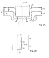
- Fig. 3A
- einen Schnitt durch zwei geclinchte Metallwerkstücke;
- Fig. 3B
- einen Teilschnitt bzw. Detail eines Bereichs des erfindungsgemässen Clinchwerkzeuges;
- Fig. 4A
- einen Schnitt, der zwei geclinchte Metallwerkstücke bzw. Metalleinzelteil und einen Teil des Clinchwerkzeuges (nicht erfindungsgemäß) zeigt, wobei der Stempel des Clinchwerkzeuges einen Durchmesser von 12mm hat;
- Fig. 4B
- einen Schnitt, der zwei geclinchte Metallwerkstücke und einen Teil des Clinchwerkzeuges (nicht erfindungsgemäß) zeigt, wobei der Stempel des Clinchwerkzeuges einen Durchmesser von 14mm hat;
- Fig. 4C
- einen Schnitt, der zwei geclinchte Metallwerkstücke und einen Teil des Clinchwerkzeuges (nicht erfindungsgemäß) zeigt, wobei der Stempel des Clinchwerkzeuges einen Durchmesser von 20mm hat;
- Fig. 5
- einen Schnitt durch ein Stahlprofil, an das ein Blechprofil bzw. Stahlprofil bzw. Stahlwinkel mit zwei Clinchverbindungen festgeclincht wurde;
- Fig. 6A
- einen Schnitt durch einen schematisch dargestellten Stempel gemäss Erfindung;
- Fig. 1
- the punch of a clinching tool and two metal workpieces that have been joined together by clinching, in a highly simplified, schematic representation;
- Fig. 2A
- a first step of the inventive clinching, in a schematic representation, wherein the two transition regions of the stamp are not shown;
- Fig. 2B
- a second step of the inventive clinching, in a schematic representation, wherein the two transition regions of the stamp are not shown;
- Fig. 2C
- a third step of the inventive clinching, in a schematic representation, wherein the two transition regions of the stamp are not shown;
- Fig. 3A
- a section through two clinched metal workpieces;
- Fig. 3B
- a partial section or detail of a portion of the inventive clinching tool;
- Fig. 4A
- a section showing two clinched metal workpieces and a part of the clinching tool (not according to the invention) , wherein the punch of the clinching tool has a diameter of 12mm;
- Fig. 4B
- a section showing two clinched metal workpieces and a part of the clinching tool (not according to the invention) , wherein the punch of the clinching tool has a diameter of 14mm;
- Fig. 4C
- a section showing two clinched metal workpieces and a part of the clinching tool (not according to the invention) , wherein the punch of the clinching tool has a diameter of 20mm;
- Fig. 5
- a section through a steel profile, onto which a sheet metal profile, steel profile member or steel angle was festgeclincht with two clinch connections;
- Fig. 6A
- a section through a stamp shown schematically according to the invention;
Es geht im Rahmen der vorliegenden Patentanmeldung, wie eingangs bereits angedeutet, um das Clinchen ohne Schneidanteil. Diese Art des Clinchens ist ein reiner Umformfügeprozess. Das Verbinden der Werkstücke wird lediglich mittels Durchsetzen in Verbindung mit Einsenken und nachfolgendem Stauchen realisiert.It is within the scope of the present patent application, as already indicated, to clinching without cutting share. This type of clinching is a pure forming process. The joining of the workpieces is realized only by means of penetration in conjunction with sinking and subsequent upsetting.
Der Grundgedanke bei der Entwicklung dieses Verfahrens ohne Schneidanteil ist vor allem das Streben nach erhöhter Verbindungssteifigkeit infolge des größeren Materialzusammenhaltes.The basic idea in the development of this process without cutting share is above all the pursuit of increased joint stiffness due to the greater material cohesion.
Das Prinzip der Erfindung ist in
Das Clinchwerkzeug 20 umfasst einen Stempel und ein Gegenwerkzeug 30, das als Matrize oder als Amboss ausgebildet sein kann. Der Stempel ist in Bezug auf seine Rotationsachse 24 rotationssymmetrisch ausgelegt. Der Stempel weist eine konzentrisch zur Rotationsachse 24 angeordnete Flanke 25 mit Flankenwinkel W auf. Bezüglich einer endständigen Stirnendfläche 23 des Stempels, wird bei der Flanke 25 zwischen einem an die Stirnendfläche 23 angrenzenden unteren Übergangsbereich 21 der Flanke 25 mit Flankenwinkel W1 sowie einem oberen Übergangsbereich 22 der Flanke 25 mit Flankenwinkel W2 unterschieden. Die beiden Übergangsbereiche 21, 22 gehen ineinander über. Dabei können sie wie in den Ausführungsbeispielen gemäss
Die
Gemäss Erfindung kommt beim Trennen vorzugsweise ein Abstreifer bzw. Niederhalter 40 zum Einsatz, der das Trennen des Stempels nach der Umformung der Metallwerkstücke 11 und 12 erleichtert. Ein solcher Abstreifer bzw. Niederhalter 40 ist besonders dann vorteilhaft, wenn der Stempel aufgrund der beim Umformen auftretenden Kräfte und Materialverformungen in der Clinchverbindung 13 festklemmen sollte. Der Abstreifer 40 stützt sich (quasi) gegenüber der Oberfläche 15 des oberen stempelseitigen Metallwerkstückes 11 ab, während der Stempel zurückgenommen bzw. zurückgezogen wird. Bei Kenntnis der vorliegenden Erfindung kann der Fachmann natürlich an Stelle eines stempelseitigen Abstreifers auch einen matrizenseitigen Abstreifer realisieren.According to the invention, preferably a scraper or hold-down 40 is used during the separation, which involves the separation of the punch facilitated after the deformation of the
Vorzugsweise werden die zu verbindenden Metallwerkstücke 11 und 12 durch einen Niederhalter, der in
Infolge des Stauchdruckes während des Einsenkens kommt es zu einem Querfließen das Werkstoffes der Metallwerkstücke 11 und 12, wodurch die Matrize 30 mit der Ausnehmung bzw. Hohlraum bzw. Verformungsraum bzw. Kuhle 31, zum Beispiel in Form einer (eingearbeiteten) Ri.ngnut, weitestgehend bzw. ganz ausgefüllt und eines Hinterschnitts des stempelseitigen Metallwerkstücks 11 im matrizenseitigen Metallwerkstück 12 erzeugt wird (siehe
Es wurden verschiedene versuche und Experimente gemacht, um den an sich bekannten Clinchprozess zu optimieren und so abzuändern, dass auch Metallwerkstücke 11, 12 geclincht werden können, die dicker sind als 4mm, ohne dass zu hohe Klemmkräfte auftreten. Es wurden Simulationen gemacht und anschliessend verschiedene Werkzeuge gefertigt und Fügeversuche durchgeführt, um die (im Experiment) ermittelten Querschnitte, Füge- und Niederhaltekräfte mit der Referenz aus der Simulation vergleichen zu können. Als Grundlage der Untersuchungen zur Werkzeugauslegung dienten Merkzeuggeataltungagrundaätze für das Clinchen ohne Schneidanteil mit starrer Matrize 30.Various attempts and experiments have been made to optimize the known clinching process and to modify it so that
Erste Untersuchungen haben ergeben, dass für die Herstellung einer Clinchverbindung 13 für einen kleinen Stempeldurchmesser (Durchmesser D2-12mm oder 14mm) Fügekräfte von ca. 400 kN bis 510 kN und für den größeren Stempeldurchmesser (D2=20mm) von ca. 670 kN (beides inkl. Niederhaltekraft) aufgewendet werden müssen. Diese Ergebnisse an sich liegen im Bereich des zu erwartenden Resultates. (Allerdings kam es trotz Werkzeugschmierung zu einem starken Klemmen des Stempels im Werkstück.)Initial investigations have shown that for the production of a
Genauere Untersuchungen zu dem Klemmen des Stempels haben gezeigt, dass das Klemmen durch eine Radialspannung verursacht wird, die auf die Flanke des Stempels einwirkt. Es hat sich gezeigt, dass es besonders im oberen Übergangsbereich 22 von der Flanke 25 zu hohen Radialspannungen kommt.
Nun wurde in einem weiteren optimierungsschritt die Geometrie des Stempels gezielt so verändert, dass eine geringere Radialspannung auf die Flanke 25 wirkt. Aufgrund der Tatsache, dass bei den ersten Werkzeugvarianten die Halsdicken tn und Hinterschnittwerte f der Stempel mit den Durchmessern D2=12 mm und D2=14 mm nahezu gleich waren, wurden weitere Optimierungen vorgenommen. Es wurden dabei auch Untersuchungen an Werkstücken mit verschiedener Gesamtwerkstückdicke tt und mit Werkstücken 11, 12 gemacht, die jeweils unterschiedliche Dicken t1, t2 haben. Dabei zeigte sich, dass handelsübliche bzw. konventionelle Stempel nicht nur die starke Tendenz zum Klemmen zeigen wenn man zu Gesamtwerkstückdicken tt > 8mm geht, sondern dass sich im Bereich zwischen den Werkstücken 11, 12 ein Hohlraum (siehe X in
Now, in a further optimization step, the geometry of the punch has been deliberately changed so that a lower radial stress acts on the
Die verschiedenen Optimierungsschritte haben zu der Erkenntnis geführt, dass die Ausgestaltung der Flanken des Stempels einen unmittelbaren Einfluss auf das Klemmen und die Bildung des Hohlraums X hat. Um diese beiden negativen Effekte zu reduzieren oder ganz zu unterbinden, wurden Stempel entwickelt und getestet, die mindestens teilweise konisch geformt sind. Bei geeigneter Auswahl des entsprechenden Flankenwinkels W, W1, W2 konnte das Klemmen reduziert oder ganz verhindert werden, ohne dass es zu einer spürbaren Hohlraumbildung kam. Es hat sich gezeigt, dass diese beiden Effekte nur teilweise zusammenhängen und sich teilweise sogar gegenläufig verhalten. Durch die Auswahl eines geeigneten Winkelbereiches konnten beide Effekte minimiert werden.The various optimization steps have led to the realization that the configuration of the flanks of the punch has a direct influence on the clamping and the formation of the cavity X. To reduce or eliminate these two negative effects, stamps have been developed and tested that are at least partially conical in shape. With a suitable selection of the corresponding flank angle W, W1, W2, the clamping could be reduced or completely prevented, without there being any noticeable cavitation. It has been shown that these two effects are only partially related and sometimes even counteracted. By selecting a suitable angle range both effects could be minimized.
Bei den in den
Einige Aspekte der verschiedenen Untersuchungen sind in den
Man kann anhand der
Wie die diversen Untersuchungen und Forschungen gezeigt haben, ist der Stempeldurchmesser nur einer von verschiedenen Parametern, die einen direkten Einfluss auf den Clinchvorgang und die Festigkeit der Clinchverbindung 13 haben. Es hat sich gezeigt, dass beim Clinchen dicker Werkstücke mit tt > 8mm die Ausgestaltung der Flanke 25 eine besonders wichtige und bedeutende Rolle spielt.As the various investigations and researches have shown, the punch diameter is only one of several parameters which have a direct influence on the clinching process and the strength of the
Die vorliegende Erfindung zeichnet sich dementsprechend dadurch aus, dass der Stempel, der bei der Umformung in die Metallwerkstücke 11 und 12 eingesenkt wird, konisch geformt ist. Die konische Form des Stempels erstreckt sich mindestens über einen Teil (als Übergangsbereiche 21, 22 bezeichnet) derjenigen Länge L des Stempels, die in die Werkstücke 11, 12 eingesenkt bzw, eingedrückt wird. Die konische Form ergibt sich dadurch, dass die Flanke 25 des Stempels, siehe
Besonders bewährt haben sich Stempel mit einem Durchmesser D2 zwischen 10mm und 20mm und mit einem Flankenwinkel W, W1, W2 der von einem ersten Winkel W1 übergeht in einen zweiten.Winkel W2, wobei der erste Winkel W1 kleiner oder gleich 10 Grad und vorzugsweise kleiner oder gleich 5 Grad beträgt und der zweite Winkel W2 kleiner oder gleich 2 Grad, und vorzugsweise 0 bis 1 Grad beträgt. Dabei befindet sich der erste Winkel W1 im unmittelbaren (unteren) Übergangsbereich 21 zur Stirnendfläche 23 (d.h. im Bereich des werkstuckseitigen Endes des Stempels) und der zweite Winkel W2 auf der vom Metallwerkstück 11, 12 wegführenden bzw. hinaushaltenden bzw. hinausragenden (oberen) Übergangsbereich 22 (d.h. im werkzeugseitigen Bereich des Stempels).Stamps having a diameter D2 between 10 mm and 20 mm and having a flank angle W, W1, W2 which changes from a first angle W1 to a second angle W2 have proven particularly useful, the first angle W1 being less than or equal to 10 degrees and preferably smaller than or equal to is equal to 5 degrees and the second angle W2 is less than or equal to 2 degrees, and preferably 0 to 1 degrees. In this case, the first angle W1 is located in the immediate (lower)
Diese Ausführung von konischen Stempeln zeigen eine deutlich geringere Tendenz zum Klemmen und es bilden sich keine (oder schwach ausgeprägte) Hohlräume X. Der Vorteil der geringeren Radialspannung und damit der geringeren Tendenz zum Klemmen wird jedoch durch die Entstehung des Hohlraumes X zwischen den Metallwerkstücken 11, 12 "erkauft", Das heisst, der Flankenwinkel W, W1, W2 kann nicht beliebig gewählt werden, da sonst der Hohlraum X zu gross und die Festigkeit der Clinchverbindung zu klein werden würde.This embodiment of conical punches show a significantly lower tendency to jam and there are no (or weak) cavities X. The advantage of the lower radial stress and thus the lower tendency to jamming is due to the formation of the cavity X between the
Ideal sind Ausführungsformen des Stempels, bei denen die durch den Flankenwinkel erzeugte Flankenrücknahme bzw. Flankenreduzierung nicht zu gross ist, da bei zu grosser Flankenrücknahme bzw. Flankenreduzierung der radial gerichtete Druck auf die Werkstücke 11, 12 zu gering wird und sich damit das Querfliessen der Werkstoffe bzw. der Metallwerkstücke reduziert.Ideal are embodiments of the stamp, in which the flank withdrawal generated by the flank angle or flank reduction is not too large, since too large flank withdrawal or flank reduction of the radially directed pressure on the
Die angegebenen Winkelwerte für W, W1, W2 haben sich auch bewährt, weil die mit diesen Stempeln erzeugten Clinchverbindungen ähnliche, vergleichbare Werte für die Halsdicke in und den Hinterschnitt f aufweisen, wie die handelsüblichen, gebräuchlichen rein zylindrischen Dünnblech-Stempel. Dies spricht für eine vergleichbare, identische Zugfestigkeit der entsprechenden Clinchverbindung 13.The indicated angle values for W, W1, W2 have also been proven, because the clinch connections produced with these punches have similar, comparable values for the neck thickness and the undercut f, as the commercially available, conventional, purely cylindrical thin-plate stamps. This speaks for a comparable, identical tensile strength of the corresponding clinching
Die konische Form des Stempels erstreckt sich mindestens über die Übergansbereiche 21, 22 mit derjenigen Länge L des Stempels, die in die Werkstücke 11, 12 eingesenkt werden. Diese Länge L bei Metallwerkstücken deren Gesamtwerkstückdicke tt > 8mm kann wie folgt ermittelt werden: 0,3 tt ≤ L ≤ 2 tt. D.h., die konisch geformten Übergangsbereiche 21, 22 entsprechen zwischen drei Zehntel der Gesamtwerkstückdicke tt und der zweifachen Gesamtwerkstückdicke tt.The conical shape of the stamp extends at least over the
Die verschiedenen erfindungsgemässen Stempelformen werden im Folgenden anhand der
Die erzielten Festigkeiten, die mit den erfindungsgemässen Stempeln, zum Beispiel mit einem Stempel mit 12mm Durchmesser und einer 5°-0°-Stempelflanke (Ausführungsform 2,
Mit dem erfindungsgemassen Stempelwerkzeug 20 kann man auch zwei Clinchverbindungen 13 nebeneinander anbringen (siche
Ein besonders vorteilhaftes Clinchwerkzeug 20 weist zwei gleichartige Stempel auf, die nebeneinander angeordnet sind und das erste Metallwerkstück 11 mit dem zweiten Metallwerkstück 12 durch zwei Clinchverbindungen zu verbinden in der Lage sind. Hier werden mit einer Zustellbewegung und einer Einsenkbewegung gleichzeitig zwei Clinchverbindungen nebeneinander erzeugt. Das Beispiel einer entsprechenden Doppelclinchverbindung ist in
Für die Abstreif(er)kraftgestaltung des Abstreifers 40 sind zwei Kriterien zu berücksichtigen. Zum einen muss die Abstreifkraft bzw. Abstreiferkraft größer als die Klemmkraft des Stempels sein. Dieser wort ist natürlich stark von der verwendeten Stempelgeometrie, wie beschrieben wurde, aber auch von der Schmierung bzw. Beschichtung der Werkzeuge abhängig. Maximale Auswerferkräfte von 30 kN bis 40 kN haben zu sehr zuverlässigen Ergebnissen geführt. Bei einer optimalen Gestaltung der Flankenwinkel w bzw. der Konizität des Stempels, reichen Auswerferkräfte von 25 kN. Für den 5°-0°-Stempel (Ausführungsform 2,
In einer besonders vorteilhaften Ausführungsform fungiert der Abstreifer 40 gleichzeitig auch als Niederhalter (41) und ist so dimensioniert, dass die Metallwerkstücke 11, 12 eine möglichst geringe Verformung erfahren, um den Verzug der Werkstücke 11, 12 so gering wie möglich zu halten bzw. frei zu halten.In a particularly advantageous embodiment, the
Es lassen sich mit den erfindungsgemässen Stempeln und den Clinchwerkzeugen, respektive Clinchmaschinen, die entsprechende Stempel aufweisen bzw. besitzen, besonders stabile und tragfähige Bauteile bzw. Baugruppen bzw. Bauelemente auf einfachste, müheloseste, kostengunstigste und zuverlässigste Art und Weise herstellen. Die Kosten für diese Bauteile bzw. Baugruppen bzw. Bauelemente mit Clinchverbindungen 13 liegen unter denen von geschweissten, genieteten oder verschraubten Verbindungen. Die Verbundmaterialkosten für Bauteile bzw. Baugruppen bzw. Bauelemente mit Clinchverbindungen 13 liegen bei Null. Weiters ist die Arbeitszeit auf ein Minimum beschränkt bzw. reduziert bzw. gedrosselt.It can be with the novel punches and clinching tools, respectively clinching machines, the corresponding stamp have or possess, particularly stable and stable components or assemblies or components manufacture the simplest, most effortless, cheapest and most reliable way. The cost of these components or assemblies or components with
Gemäss Erfindung können Clinchverbindungen 13 ohne Schneidanteil auch mit öffnender Matrize erzeugt werden. Dabei werden federnd gelagerte Lamellen der Matrize nach dem Finsenkprozess durch das radiale Fließen des Werkstückmaterials unterhalb des Stempels nach außen gedrückt und somit die Ausbildung des Hinterschnittes ermöglicht.According to the invention, clinching
Neben den Vorteilen des konventionellen Clinchens kann auch das matrizenlosealinchen eingesetzt werden, bei dem als Gegenwerkzeug 30 ein Amboss mit flacher Bearbeitungsfläche zum Einsatz kommt, wobei der Stempel die auf der Bearbeitungsfläche angeordneten Metalleinzelteile bzw. Metallteile bzw. Metallwerkstücke in einem Überschneidungsbereich bzw. Überlappungsbereich derart verformt, dass sich erst eine ambosseitige Erhebung und dann durch radiales Fliessen der Werkstoffe ein lokaler Hinterschnitt f herausbildet. Das Matrizenloseclinchen weist aufgrund seines speziellen Funktionsprinzips die folgenden vorteile auf:
- Ein Versatz zwischen (Füge) Stempel und Gegenwerkzeug (Amboss) beeinträchtigt die
Qualität der Verbindung 13 nicht. Dadurch verringern sich die Genauigkeitsanforderungen an die Fügemaschine. - Zeitaufwändige Einrichtarbeiten können entfallen.
- Der Verschleiß sinkt und die Prozesssicherheit steigt, da keine Ausbrüche an der Matrizenkante mehr auftreten können.
- Für alle Fugeaufgaben kann der gleiche Amboss verwendet werden. Ein Matrizenwechsel beim Wechsel der Fügeaufgabe, wie beim herkömmlichen Clinchen ist nicht mehr notwendig.
Die Fügeverbindungen 13 sind flacher und weniger störend als die mit dem konventionellen Clinchen erzeugten Verbindungen.- Ein Ändern der Blechdicke ist ohne Werkzeugwechsel möglich und spart wertvolle Arbeitszeit.
- Eine Änderung der Werkstoffpaarung geht ohne Aufwand vonstatten.
- Matrizenloses Clinchen erhöht die Anzahl der Clinchverbindungen bzw. Fügepunkte pro Werkzeugsatz bzw. pro (Füge) Stempel.
- An offset between (joint) punch and counter tool (anvil) does not affect the quality of the
connection 13. This reduces the accuracy requirements of the joining machine. - Time-consuming set-up work can be omitted.
- The wear decreases and the process reliability increases, since no more breakouts at the die edge can occur.
- For all Fugeaufgaben the same anvil can be used. A die change when changing the joining task, as in conventional clinching is no longer necessary.
- The
joint connections 13 are flatter and less disturbing than the compounds produced by conventional clinching. - Changing the sheet thickness is possible without changing tools and saves valuable working time.
- A change in the material combination is without effort vonstatten.
- Die-free clinching increases the number of clinch connections or joining points per tool set or per (joining) punch.
Claims (16)
- Clinching tool (20) for producing a load-bearing connection of a first metal workpiece (11) with a second metal workpiece (12), wherein the clinching tool (20) comprises a die tool and a counter-tool (30) which together form, by deformation of the two metal workpieces (11, 12), a clinch connection (13) connecting together the first metal workpiece (11) and the second metal workpiece (12), and wherein the die tool comprises a die (21, 22), which is constructed to be rotationally symmetrical with respect to a rotational axis (24) of the die and has a flank (25) arranged concentrically with respect to the rotational axis and a front end surface (23) lying perpendicularly to the rotational axis (24), wherein the flank (25) of the die is conically shaped at least in the lower transition region (21) to the front end surface (23) and has a flank angle (W, W1, W2) which is smaller than or equal to 10 degrees, preferably smaller than or equal to 5 degrees, characterised in that the flank angle (W, W1, W2) goes over from a first angle (W1) directly at the end of the lower transition region (21), which leads to the front end surface (23), to a second angle (W2) of an upper transition region (22), wherein the first angle (W1) is larger than the second angle (W2), and that during the deforming the die is sunk also in the upper transition region (22) at least in part into the metal workpieces (11, 12).
- Clinching tool (20) according to claim 1, characterised in that the entire length (L) of the die sunk into the metal workpieces (11, 12) during the deforming is conically shaped.
- Clinching tool (20) according to claim 1 or 2, characterised in that the first angle (W1) is smaller than or equal to 10 degrees and preferably smaller than or equal to 5 degrees and the second angle (W2) is smaller than or equal to 2 degrees and is preferably 0 to 1 degrees.
- Clinching tool (20) according to any one of the preceding claims, characterised in that the die has a diameter (D2) between 10 and 30 millimetres or 35 millimetres, wherein the diameter (D2) preferably lies between 12 and 20 millimetres or 25 millimetres (inclusive).
- Clinching tool (20) according to any one of the preceding claims, characterised in that the counter-tool (30) is constructed as an anvil having a flat, even, planar, horizontal or level working area or surface.
- Clinching tool (20) according to any one of the preceding claims 1 to 5,
characterised in that the counter-tool (30) is constructed as a matrix having a recess, cavity, deformation space or depression (31). - Clinching tool (20) according to any one of the preceding claims, characterised in that it contains, has or comprises a holding-down device (41, 40) for fixing the metal workpieces (11, 12) and a stripper (40) for separating the die after deformation of the metal workpieces (11, 12).
- Clinching tool (20) according to any one of the preceding claims, characterised in that it comprises two identical dies which are arranged adjacent to one another and are capable of connecting the first metal workpiece (11) with the second metal workpiece (12) by two clinch connections (13).
- Method of using a deformation-based connecting technology for producing a load-bearing connection of a first metal workpiece (11) and a second metal workpiece (12), wherein a clinch connection (13) connecting the first metal workpiece (11) with the second metal workpiece (12) is formed by local deformation by means of a die tool (20) and a counter-tool (30), comprising the steps:- superimposing and preparing or aligning the first metal workpiece (11) and the second metal workpiece (12) on a processing surface of the counter-tool (30),- advancing a die of the die tool (20),- sinking the die into the two assembled metal workpieces (11, 12) until the underside (14) of the second metal workpiece (12) bears against a region of the counter-tool (30) and- withdrawing the die,characterised in that the die has a flank (25) which is conically shaped at least in a lower transition region (21) to a front end surface (23) and has a flank angle (W, W1, W2) smaller than or equal to 10 degrees, preferably smaller than or equal to 5 degrees, wherein the first angle (W1) is greater than the second angle (W2) and during sinking of the die the upper transition region (21) also penetrates at least in part into the metal workpieces (11, 12).
- Method according to claim 9, characterised in that a stripper (40) is used during withdrawal of the die to enable separation when jamming of the die or the die tool (20) of metal workpieces (11, 12) occurs.
- Method according to claims 9 and 10, characterised in that the stripper (40) is advanced against a surface (15) of the first metal workpiece (11) prior to the separation and that during the separation a force is exerted against the metal workpieces (11, 12) by means of the stripper (40) whilst a force acting in opposite direction retracts the die.
- Method according to claim 9, 10 or 11, characterised in that the counter-tool (30) is constructed as a matrix having a recess, cavity, deformation space or depression (31) in the region of the processing surface, wherein the die deforms the metal workpieces (11, 12), which are arranged on the processing surface, (in an intersection region or overlap region above) the recess, cavity, deformation space or depression (31) in such a manner than a local undercut (f) is formed by radial flow of the materials into the recess, cavity, deformation space or depression (31).
- Method according to claim 9, 10 or 11, characterised in that an anvil with an even, planar, horizontal, level or flat processing area or surface is used as counter-tool (30), wherein the die deforms the metal workpieces (11, 12), which are arranged or aligned on the processing surface, in an intersection region or overlap region in such a manner that firstly an elevation is formed at the anvil side and then, through radial flow of the materials, a local small undercut or undercutting (f).
- Use of a clinching tool (20) according to any one of the preceding claims 1 to 8,
characterised in that the clinching tool (20) is used to firmly connect together two metal workpieces (11, 12) by at least one local undercut (13), wherein the two metal workpieces (11, 12) have a total thickness (tt) greater than 8 millimetres. - Use according to claim 14, characterised in that the first metal workpiece (11) is thicker than the second metal workpiece (12).
- Use according to claim 14 and/or 15, characterised in that either the first metal workpiece (11) or the second metal workpiece (12) is a steel profile member, plate profile member, steel angle member, steel sheet, sheet iron, shaped tube, plate member, plate strip or steel girder.
Priority Applications (2)
| Application Number | Priority Date | Filing Date | Title |
|---|---|---|---|
| PL08700550T PL2117746T3 (en) | 2007-02-13 | 2008-02-08 | Method and tool for clinching thick sheet metal, and use of the tool |
| EP08700550A EP2117746B1 (en) | 2007-02-13 | 2008-02-08 | Method and tool for clinching thick sheet metal, and use of the tool |
Applications Claiming Priority (3)
| Application Number | Priority Date | Filing Date | Title |
|---|---|---|---|
| EP07102274 | 2007-02-13 | ||
| PCT/CH2008/000046 WO2008098389A1 (en) | 2007-02-13 | 2008-02-08 | Method and tool for clinching thick sheet metal, and use of the tool |
| EP08700550A EP2117746B1 (en) | 2007-02-13 | 2008-02-08 | Method and tool for clinching thick sheet metal, and use of the tool |
Publications (2)
| Publication Number | Publication Date |
|---|---|
| EP2117746A1 EP2117746A1 (en) | 2009-11-18 |
| EP2117746B1 true EP2117746B1 (en) | 2010-04-28 |
Family
ID=38198192
Family Applications (1)
| Application Number | Title | Priority Date | Filing Date |
|---|---|---|---|
| EP08700550A Not-in-force EP2117746B1 (en) | 2007-02-13 | 2008-02-08 | Method and tool for clinching thick sheet metal, and use of the tool |
Country Status (23)
| Country | Link |
|---|---|
| US (1) | US9283612B2 (en) |
| EP (1) | EP2117746B1 (en) |
| JP (1) | JP5249951B2 (en) |
| KR (1) | KR20090108693A (en) |
| CN (1) | CN101610859B (en) |
| AT (1) | ATE465829T1 (en) |
| AU (1) | AU2008215090B2 (en) |
| BR (1) | BRPI0807454A2 (en) |
| CA (1) | CA2675307C (en) |
| DE (1) | DE502008000600D1 (en) |
| DK (1) | DK2117746T3 (en) |
| ES (1) | ES2345304T3 (en) |
| HK (1) | HK1137962A1 (en) |
| IL (1) | IL199719A (en) |
| MX (1) | MX2009007789A (en) |
| MY (1) | MY150171A (en) |
| NZ (1) | NZ578770A (en) |
| PL (1) | PL2117746T3 (en) |
| RU (1) | RU2464118C2 (en) |
| TW (1) | TWI454323B (en) |
| UA (1) | UA99607C2 (en) |
| WO (1) | WO2008098389A1 (en) |
| ZA (1) | ZA200904683B (en) |
Families Citing this family (33)
| Publication number | Priority date | Publication date | Assignee | Title |
|---|---|---|---|---|
| CN101934339B (en) * | 2010-09-21 | 2012-10-17 | 上海交通大学 | Ring-shaped electro-plastic rivet-free riveting device |
| DE202011000731U1 (en) * | 2011-03-30 | 2011-06-01 | Schmitz Cargobull AG, 48341 | Profile carrier for a vehicle chassis and utility vehicle chassis with such a profile carrier |
| DE102011122037A1 (en) * | 2011-12-22 | 2013-06-27 | Kathrein-Werke Kg | Method for producing a high-frequency electrical connection between two plate sections and an associated high-frequency electrical connection |
| JP2013139048A (en) * | 2012-01-05 | 2013-07-18 | Tokyo Institute Of Technology | Method of joining material to be joined |
| CN102601248A (en) * | 2012-03-16 | 2012-07-25 | 金德精密配件(苏州)有限公司 | Riveting method of metal sheets |
| DE102012108161B4 (en) * | 2012-09-03 | 2016-09-22 | Bwg Bergwerk- Und Walzwerk-Maschinenbau Gmbh | Method and device for joining metal strips |
| CN103056235A (en) * | 2012-12-31 | 2013-04-24 | 张家港固耐特围栏系统有限公司 | Board connecting mold used for rails |
| KR101323221B1 (en) * | 2013-04-23 | 2013-10-30 | 김강민 | Method for joinning cable tray by non-welding |
| DE102013210370A1 (en) * | 2013-06-04 | 2014-12-04 | Böllhoff Verbindungstechnik GmbH | Adjustment aid for a joining device with a punch and a counter tool and a method for adjusting the joining device |
| KR101335612B1 (en) * | 2013-07-17 | 2013-12-02 | 김강민 | Method of installing cable tray |
| EP2832471B1 (en) * | 2013-08-02 | 2016-02-03 | MAGNA STEYR Engineering AG & Co KG | Method for producing a punch rivet connection and composite component |
| DE102013216820A1 (en) * | 2013-08-23 | 2015-02-26 | Volkswagen Aktiengesellschaft | Method for connecting at least two sheet metal parts |
| KR101407059B1 (en) * | 2013-09-26 | 2014-06-12 | 김강민 | Structure of cable tray |
| US10328481B2 (en) | 2014-03-18 | 2019-06-25 | Btm Company Llc | Clinching punch and apparatus |
| CN104438889B (en) * | 2014-10-24 | 2017-01-18 | 安徽启光能源科技研究院有限公司 | Automatic rivet disengaging device for rivetless riveting device and rivet disengaging method thereof |
| CN105478646B (en) * | 2015-11-20 | 2017-11-03 | 西安交通大学 | A kind of sheet material connection method of use hard riveting post one-step method riveting |
| ITUB20160504A1 (en) * | 2016-01-15 | 2017-07-15 | System Spa | FORMAT COMPENSATOR FOR A PRESSING DEVICE |
| CN107363178A (en) * | 2016-05-12 | 2017-11-21 | 中兴通讯股份有限公司 | A kind of riveting equipment and its application method |
| JP6607837B2 (en) * | 2016-10-06 | 2019-11-20 | 三菱重工業株式会社 | Thermal barrier coating film, turbine member and thermal barrier coating method |
| DE202017104046U1 (en) * | 2017-02-23 | 2017-07-27 | Ebm-Papst Landshut Gmbh | Connection unit for a blower |
| DE102017116560A1 (en) * | 2017-07-21 | 2019-01-24 | Tox Pressotechnik Gmbh & Co. Kg | Device for joining a workpiece |
| JP7000827B2 (en) * | 2017-12-08 | 2022-01-19 | トヨタ自動車株式会社 | Joined structure |
| KR102018959B1 (en) | 2017-12-15 | 2019-09-06 | 서진산업 주식회사 | Clincging device using two step press type |
| KR102018958B1 (en) | 2017-12-15 | 2019-09-06 | 서진산업 주식회사 | Sliding clincging device |
| JP7035695B2 (en) * | 2018-03-26 | 2022-03-15 | トヨタ自動車株式会社 | Joining equipment and manufacturing method of joined body |
| DE102019110221A1 (en) * | 2018-04-20 | 2019-10-24 | Magna Closures Inc. | Connection mechanism for a thin-walled pipe |
| JP7182989B2 (en) * | 2018-10-12 | 2022-12-05 | 株式会社アーレスティ | Joined product manufacturing method and plate member quality control method |
| CN109248964A (en) * | 2018-10-30 | 2019-01-22 | 福州大学 | A kind of no rivet connector and its working method |
| DE202018107289U1 (en) * | 2018-12-19 | 2020-03-23 | Reinz-Dichtungs-Gmbh | Plate-like fluid container |
| NL1043110B1 (en) * | 2018-12-24 | 2020-07-21 | Bosch Gmbh Robert | Process for manufacturing a laminate of stacked metal parts including a multi-layer blanking process step |
| CN109664084B (en) * | 2019-01-31 | 2023-06-20 | 桂林电子科技大学 | Rolling device for plate connection and application method thereof |
| DE102019134024A1 (en) * | 2019-12-11 | 2021-06-17 | Eckold Gmbh & Co. Kg | Process for joining two metal sheets with a variable total thickness |
| CN111531045B (en) * | 2020-04-06 | 2022-03-22 | 慈溪市汉德电器有限公司 | Metal piece riveting process |
Family Cites Families (37)
| Publication number | Priority date | Publication date | Assignee | Title |
|---|---|---|---|---|
| US3555831A (en) * | 1968-09-16 | 1971-01-19 | Texaco Inc | Composite foundation member and method |
| US5435049A (en) * | 1980-09-08 | 1995-07-25 | Btm Corporation | Apparatus for joining sheet material |
| US5267383A (en) * | 1980-09-08 | 1993-12-07 | Btm Corporation | Apparatus for joining sheet material |
| DE3575386D1 (en) * | 1984-03-22 | 1990-02-22 | Eckold Vorrichtung | ENFORCEMENT PROCEDURE. |
| DE8408792U1 (en) * | 1984-03-22 | 1985-07-18 | Walter Eckold GmbH & Co KG Vorrichtungs- und Gerätebau, 3424 St Andreasberg | Device for connecting sheet metal lying flat on top of one another by means of pressing through and extrusion |
| EP0215449B1 (en) * | 1985-09-14 | 1991-05-22 | RAPP, Eugen | Method and device for joining thin plates |
| US4803767A (en) * | 1986-08-29 | 1989-02-14 | Lamb Robo | Clinching tool |
| DE3710929A1 (en) * | 1987-04-01 | 1988-10-13 | Eugen Rapp | METHOD AND DEVICE FOR CONNECTING LAYER THIN PLATES |
| DE8803773U1 (en) * | 1988-03-19 | 1988-06-01 | Walter Eckold GmbH & Co KG Vorrichtungs- und Gerätebau, 3424 St Andreasberg | Tool set designed for use with a press to join several superimposed sheets by means of local flow pressing |
| DE3836937A1 (en) * | 1988-10-29 | 1990-05-03 | Eckold Vorrichtung | ENFORCEMENT DEVICE |
| US5528815A (en) * | 1990-04-03 | 1996-06-25 | Webb; Edward L. T. | Clinching tool for sheet metal joining |
| US5305517A (en) * | 1991-09-23 | 1994-04-26 | Schleicher Louis C | Apparatus for forming clinch joints |
| DE9114122U1 (en) * | 1991-11-13 | 1993-04-01 | Eckold GmbH & Co KG, 3424 St. Andreasberg | Device for joining sheet metal parts |
| US5230136A (en) * | 1992-05-04 | 1993-07-27 | Savair Inc. | Punch and die set for sheet metal clinching |
| US5432989A (en) * | 1992-10-27 | 1995-07-18 | Archer Manufacturing Corporation | Apparatus and method for joining sheet material |
| SE9301097D0 (en) * | 1993-03-31 | 1993-03-31 | Attexor Equipements Sa | A METHOD FOR JOINING TOGETHER TWO OR SEVERAL OVERLAYING SHEET FORMED MEMBERS, AN APPARATUS FOR CARRYING OUT SAID METHOD AND A JOINT RESULTING FROM SAID METHOD |
| US5984563A (en) * | 1994-07-22 | 1999-11-16 | Btm Corporation | Apparatus for joining sheet material and joint formed therein |
| JP2780967B2 (en) * | 1996-08-29 | 1998-07-30 | ナショナル住宅産業株式会社 | Work coupling device |
| US5782130A (en) * | 1997-01-27 | 1998-07-21 | Btm Corporation | Apparatus for retaining tools |
| US6722013B1 (en) * | 1998-03-25 | 2004-04-20 | Tox Pressotechnik Gmbh | Method, tool and punch for joining components to a plate |
| DE19843834C2 (en) * | 1998-09-24 | 2001-05-03 | Rudolf Mueller | Joining device and clinching method |
| US6217115B1 (en) * | 1999-04-20 | 2001-04-17 | Dura Global Technologies, Inc. | Simplified linkage assembly |
| EP1261443B1 (en) * | 2000-02-09 | 2009-01-28 | Stresswave, Inc. | Method and apparatus for manufacturing structures with improved fatigue life |
| BR0111516B1 (en) * | 2000-06-08 | 2009-08-11 | tubular rivet connection between two metal blades and method for producing the same. | |
| DE10031073B4 (en) * | 2000-06-30 | 2016-11-24 | Gustav Klauke Gmbh | Method of riveting |
| DE20106207U1 (en) * | 2001-04-09 | 2001-06-21 | Böllhoff GmbH, 33649 Bielefeld | Drive device for a press tool |
| DE10245604A1 (en) * | 2002-09-30 | 2004-04-15 | Fraunhofer-Gesellschaft zur Förderung der angewandten Forschung e.V. | Method and device for the permanent connection of overlapping, plate-shaped components |
| US6814531B2 (en) * | 2002-11-18 | 2004-11-09 | General Motors Corporation | Rotation restraining self-piercing rivet |
| JP4465581B2 (en) * | 2002-11-29 | 2010-05-19 | 日立オートモティブシステムズ株式会社 | Polymerization plate, polymerization tube, method of overhanging polymerization tube, tool |
| JP4306507B2 (en) * | 2004-03-26 | 2009-08-05 | 日産自動車株式会社 | Caulking and joining method for plate material and caulking and joining apparatus for plate material |
| WO2006047848A1 (en) * | 2004-11-08 | 2006-05-11 | Falconbridge Limited | Clinching tool, die and method for use thereof |
| US20060096075A1 (en) * | 2004-11-08 | 2006-05-11 | Victor Robinson | Clinching tool, die and method for use thereof |
| DE102005000023A1 (en) * | 2005-03-22 | 2006-09-28 | Hilti Ag | Draft assembly and method thereto |
| JP5007872B2 (en) * | 2005-03-24 | 2012-08-22 | 日立オートモティブシステムズ株式会社 | Single cylinder hydraulic shock absorber and bracket mounting method for single cylinder hydraulic shock absorber |
| CN2838800Y (en) * | 2005-11-09 | 2006-11-22 | 青岛港(集团)有限公司 | Sheathing top edge folding rivetter |
| CN101512166B (en) * | 2006-07-31 | 2012-07-04 | 丰田自动车株式会社 | Component and method of manufacturing the same |
| DE102008003463A1 (en) * | 2008-01-08 | 2009-07-09 | Trw Automotive Gmbh | Method for producing a bearing shell assembly, and bearing shell assembly for a ball joint |
-
2008
- 2008-02-08 EP EP08700550A patent/EP2117746B1/en not_active Not-in-force
- 2008-02-08 ZA ZA200904683A patent/ZA200904683B/en unknown
- 2008-02-08 CA CA2675307A patent/CA2675307C/en not_active Expired - Fee Related
- 2008-02-08 DE DE502008000600T patent/DE502008000600D1/en active Active
- 2008-02-08 NZ NZ578770A patent/NZ578770A/en unknown
- 2008-02-08 AU AU2008215090A patent/AU2008215090B2/en not_active Ceased
- 2008-02-08 CN CN2008800047937A patent/CN101610859B/en not_active Expired - Fee Related
- 2008-02-08 WO PCT/CH2008/000046 patent/WO2008098389A1/en active Application Filing
- 2008-02-08 UA UAA200908504A patent/UA99607C2/en unknown
- 2008-02-08 AT AT08700550T patent/ATE465829T1/en active
- 2008-02-08 DK DK08700550.0T patent/DK2117746T3/en active
- 2008-02-08 JP JP2009549354A patent/JP5249951B2/en not_active Expired - Fee Related
- 2008-02-08 MY MYPI20092944A patent/MY150171A/en unknown
- 2008-02-08 RU RU2009134105/02A patent/RU2464118C2/en not_active IP Right Cessation
- 2008-02-08 BR BRPI0807454-2A2A patent/BRPI0807454A2/en not_active Application Discontinuation
- 2008-02-08 KR KR1020097014758A patent/KR20090108693A/en not_active Application Discontinuation
- 2008-02-08 ES ES08700550T patent/ES2345304T3/en active Active
- 2008-02-08 MX MX2009007789A patent/MX2009007789A/en active IP Right Grant
- 2008-02-08 PL PL08700550T patent/PL2117746T3/en unknown
- 2008-02-13 TW TW097105002A patent/TWI454323B/en not_active IP Right Cessation
-
2009
- 2009-07-07 IL IL199719A patent/IL199719A/en not_active IP Right Cessation
- 2009-08-12 US US12/539,903 patent/US9283612B2/en not_active Expired - Fee Related
-
2010
- 2010-03-25 HK HK10103135.8A patent/HK1137962A1/en not_active IP Right Cessation
Also Published As
| Publication number | Publication date |
|---|---|
| CA2675307A1 (en) | 2008-08-21 |
| HK1137962A1 (en) | 2010-08-13 |
| NZ578770A (en) | 2012-06-29 |
| JP2010517786A (en) | 2010-05-27 |
| ZA200904683B (en) | 2010-09-29 |
| IL199719A0 (en) | 2010-04-15 |
| PL2117746T3 (en) | 2010-10-29 |
| ES2345304T3 (en) | 2010-09-20 |
| IL199719A (en) | 2013-05-30 |
| RU2464118C2 (en) | 2012-10-20 |
| CA2675307C (en) | 2015-05-05 |
| MX2009007789A (en) | 2009-07-31 |
| TW200916221A (en) | 2009-04-16 |
| US9283612B2 (en) | 2016-03-15 |
| MY150171A (en) | 2013-12-13 |
| RU2009134105A (en) | 2011-03-20 |
| CN101610859B (en) | 2013-07-17 |
| BRPI0807454A2 (en) | 2014-05-20 |
| AU2008215090B2 (en) | 2013-01-10 |
| UA99607C2 (en) | 2012-09-10 |
| DE502008000600D1 (en) | 2010-06-10 |
| AU2008215090A1 (en) | 2008-08-21 |
| ATE465829T1 (en) | 2010-05-15 |
| DK2117746T3 (en) | 2010-08-16 |
| US20100018278A1 (en) | 2010-01-28 |
| CN101610859A (en) | 2009-12-23 |
| EP2117746A1 (en) | 2009-11-18 |
| TWI454323B (en) | 2014-10-01 |
| KR20090108693A (en) | 2009-10-16 |
| JP5249951B2 (en) | 2013-07-31 |
| WO2008098389A1 (en) | 2008-08-21 |
Similar Documents
| Publication | Publication Date | Title |
|---|---|---|
| EP2117746B1 (en) | Method and tool for clinching thick sheet metal, and use of the tool | |
| EP2117747B1 (en) | Method for clinching thick metal workpieces and use of a clinching tool | |
| EP1198309B1 (en) | Method, device and auxiliary joining part for effecting a mechanical joining | |
| EP2084033B1 (en) | Structural element for a vehicle seat | |
| DE102005031916B4 (en) | Semi-holed punch rivet for mechanical joining and method for producing a joint connection | |
| EP1442809B1 (en) | Method for producing parts with hollow body | |
| EP3505270B1 (en) | Setting unit for a punch rivet device, punch rivet device and method for manufacturing the same | |
| EP1115518B1 (en) | Method and device for connecting overlapping flat parts | |
| DE102005037914B3 (en) | Method for setting punched rivets | |
| DE4404659B4 (en) | Method for producing a riveted connection and tool for carrying out the method | |
| DE102016113357A1 (en) | Connection method for sheet metal materials and vehicle body or chassis | |
| DE10213793A1 (en) | Method, device and auxiliary joining part for joining at least two components | |
| DE10124920A1 (en) | Riveting method e.g. for automobile body panels, uses sonotrode for oscillation of rivet at defined frequency | |
| DE102017205940A1 (en) | Method for producing a composite component and motor vehicle | |
| DE19945743A1 (en) | Method and device for connecting overlapping plate-shaped components | |
| DE19927101A1 (en) | Mechanical joining by clinch process involves punch and pressure pad and top and bottom stops to control pad movement and upset material neck region. | |
| DE10102712B4 (en) | Method for connecting at least partially overlapping components and device therefor | |
| DE19913757A1 (en) | Fabrication of rivet connection in flat steel sheets uses pressurized fluid fed into bottom die to generate lateral force to press sheet material against rivet jacket | |
| DE102008062850B4 (en) | Method for producing a deep-drawn part and a method for controlling a deep-drawing device and a deep-drawing device | |
| DE102015000982B4 (en) | Method for connecting several flat components and component arrangement | |
| DE19643076C2 (en) | Device for punching and joining at least two sheet metal parts in one operation | |
| DE69216395T2 (en) | METHOD OF RIVETING AND DEVICE FOR IMPLEMENTING THE METHOD | |
| DE102015008171A1 (en) | Apparatus and method for processing a sheet metal component | |
| DE10151659B4 (en) | Method for joining at least two components and device therefor | |
| DE10323740B4 (en) | Assembly, with a punch rivet and at least two components to be joined |
Legal Events
| Date | Code | Title | Description |
|---|---|---|---|
| PUAI | Public reference made under article 153(3) epc to a published international application that has entered the european phase |
Free format text: ORIGINAL CODE: 0009012 |
|
| 17P | Request for examination filed |
Effective date: 20090831 |
|
| AK | Designated contracting states |
Kind code of ref document: A1 Designated state(s): AT BE BG CH CY CZ DE DK EE ES FI FR GB GR HR HU IE IS IT LI LT LU LV MC MT NL NO PL PT RO SE SI SK TR |
|
| GRAP | Despatch of communication of intention to grant a patent |
Free format text: ORIGINAL CODE: EPIDOSNIGR1 |
|
| GRAS | Grant fee paid |
Free format text: ORIGINAL CODE: EPIDOSNIGR3 |
|
| GRAA | (expected) grant |
Free format text: ORIGINAL CODE: 0009210 |
|
| AK | Designated contracting states |
Kind code of ref document: B1 Designated state(s): AT BE BG CH CY CZ DE DK EE ES FI FR GB GR HR HU IE IS IT LI LT LU LV MC MT NL NO PL PT RO SE SI SK TR |
|
| REG | Reference to a national code |
Ref country code: GB Ref legal event code: FG4D Free format text: NOT ENGLISH |
|
| REG | Reference to a national code |
Ref country code: CH Ref legal event code: EP |
|
| REG | Reference to a national code |
Ref country code: IE Ref legal event code: FG4D Free format text: LANGUAGE OF EP DOCUMENT: GERMAN |
|
| REF | Corresponds to: |
Ref document number: 502008000600 Country of ref document: DE Date of ref document: 20100610 Kind code of ref document: P |
|
| REG | Reference to a national code |
Ref country code: NL Ref legal event code: T3 |
|
| REG | Reference to a national code |
Ref country code: SE Ref legal event code: TRGR |
|
| REG | Reference to a national code |
Ref country code: GR Ref legal event code: EP Ref document number: 20100401497 Country of ref document: GR |
|
| REG | Reference to a national code |
Ref country code: HK Ref legal event code: DE Ref document number: 1137962 Country of ref document: HK |
|
| REG | Reference to a national code |
Ref country code: DK Ref legal event code: T3 |
|
| REG | Reference to a national code |
Ref country code: ES Ref legal event code: FG2A Ref document number: 2345304 Country of ref document: ES Kind code of ref document: T3 |
|
| LTIE | Lt: invalidation of european patent or patent extension |
Effective date: 20100428 |
|
| REG | Reference to a national code |
Ref country code: NO Ref legal event code: T2 Effective date: 20100428 |
|
| REG | Reference to a national code |
Ref country code: SK Ref legal event code: T3 Ref document number: E 7531 Country of ref document: SK |
|
| PG25 | Lapsed in a contracting state [announced via postgrant information from national office to epo] |
Ref country code: LT Free format text: LAPSE BECAUSE OF FAILURE TO SUBMIT A TRANSLATION OF THE DESCRIPTION OR TO PAY THE FEE WITHIN THE PRESCRIBED TIME-LIMIT Effective date: 20100428 |
|
| REG | Reference to a national code |
Ref country code: PL Ref legal event code: T3 |
|
| REG | Reference to a national code |
Ref country code: HK Ref legal event code: GR Ref document number: 1137962 Country of ref document: HK |
|
| PG25 | Lapsed in a contracting state [announced via postgrant information from national office to epo] |
Ref country code: HR Free format text: LAPSE BECAUSE OF FAILURE TO SUBMIT A TRANSLATION OF THE DESCRIPTION OR TO PAY THE FEE WITHIN THE PRESCRIBED TIME-LIMIT Effective date: 20100428 Ref country code: LV Free format text: LAPSE BECAUSE OF FAILURE TO SUBMIT A TRANSLATION OF THE DESCRIPTION OR TO PAY THE FEE WITHIN THE PRESCRIBED TIME-LIMIT Effective date: 20100428 Ref country code: IS Free format text: LAPSE BECAUSE OF FAILURE TO SUBMIT A TRANSLATION OF THE DESCRIPTION OR TO PAY THE FEE WITHIN THE PRESCRIBED TIME-LIMIT Effective date: 20100828 Ref country code: SI Free format text: LAPSE BECAUSE OF FAILURE TO SUBMIT A TRANSLATION OF THE DESCRIPTION OR TO PAY THE FEE WITHIN THE PRESCRIBED TIME-LIMIT Effective date: 20100428 |
|
| PG25 | Lapsed in a contracting state [announced via postgrant information from national office to epo] |
Ref country code: CY Free format text: LAPSE BECAUSE OF FAILURE TO SUBMIT A TRANSLATION OF THE DESCRIPTION OR TO PAY THE FEE WITHIN THE PRESCRIBED TIME-LIMIT Effective date: 20100616 |
|
| PG25 | Lapsed in a contracting state [announced via postgrant information from national office to epo] |
Ref country code: EE Free format text: LAPSE BECAUSE OF FAILURE TO SUBMIT A TRANSLATION OF THE DESCRIPTION OR TO PAY THE FEE WITHIN THE PRESCRIBED TIME-LIMIT Effective date: 20100428 |
|
| PG25 | Lapsed in a contracting state [announced via postgrant information from national office to epo] |
Ref country code: RO Free format text: LAPSE BECAUSE OF FAILURE TO SUBMIT A TRANSLATION OF THE DESCRIPTION OR TO PAY THE FEE WITHIN THE PRESCRIBED TIME-LIMIT Effective date: 20100428 |
|
| PLBE | No opposition filed within time limit |
Free format text: ORIGINAL CODE: 0009261 |
|
| 26N | No opposition filed |
Effective date: 20110131 |
|
| PLAA | Information modified related to event that no opposition was filed |
Free format text: ORIGINAL CODE: 0009299DELT |
|
| PLAA | Information modified related to event that no opposition was filed |
Free format text: ORIGINAL CODE: 0009299DELT |
|
| PLBE | No opposition filed within time limit |
Free format text: ORIGINAL CODE: 0009261 |
|
| STAA | Information on the status of an ep patent application or granted ep patent |
Free format text: STATUS: NO OPPOSITION FILED WITHIN TIME LIMIT |
|
| D26N | No opposition filed (deleted) | ||
| RIN2 | Information on inventor provided after grant (corrected) |
Inventor name: TROJER, ANDREAS Inventor name: ISRAEL, MARKUS Inventor name: ILLEDITS, THOMAS Inventor name: MATHEISL, MICHAEL Inventor name: NOVACEK, THOMAS Inventor name: MAUERMANN, REINHARD |
|
| PG25 | Lapsed in a contracting state [announced via postgrant information from national office to epo] |
Ref country code: MC Free format text: LAPSE BECAUSE OF NON-PAYMENT OF DUE FEES Effective date: 20110228 |
|
| PG25 | Lapsed in a contracting state [announced via postgrant information from national office to epo] |
Ref country code: MT Free format text: LAPSE BECAUSE OF FAILURE TO SUBMIT A TRANSLATION OF THE DESCRIPTION OR TO PAY THE FEE WITHIN THE PRESCRIBED TIME-LIMIT Effective date: 20100428 |
|
| REG | Reference to a national code |
Ref country code: SK Ref legal event code: TA4A Free format text: (72) TROJER ANDREAS, WIEN, AT; MATHEISL MICHAEL, V?SENDORF, AT; ILLEDITS THOMAS, NEUFELD, AT; NOVACEK THOMAS, SCHWECHAT, AT; ISRAEL MARKUS, DRESDEN, DE; MAUERMANN REINHARD, DRESDEN, DE; Effective date: 20111114 Ref country code: SK Ref legal event code: TC4A Ref document number: E 7531 Country of ref document: SK Owner name: MAUERMANN REINHARD, DRESDEN, DE Effective date: 20111114 Ref country code: SK Ref legal event code: TC4A Ref document number: E 7531 Country of ref document: SK Owner name: MATHEISL MICHAEL, VOESENDORF, AT Effective date: 20111114 Ref country code: SK Ref legal event code: TC4A Ref document number: E 7531 Country of ref document: SK Owner name: NOVACEK THOMAS, SCHWECHAT, AT Effective date: 20111114 Ref country code: SK Ref legal event code: TC4A Ref document number: E 7531 Country of ref document: SK Owner name: TROJER ANDREAS, WIEN, AT Effective date: 20111114 Ref country code: SK Ref legal event code: TC4A Ref document number: E 7531 Country of ref document: SK Owner name: ILLEDITS THOMAS, NEUFELD, AT Effective date: 20111114 Ref country code: SK Ref legal event code: TC4A Ref document number: E 7531 Country of ref document: SK Owner name: ISRAEL MARKUS, DRESDEN, DE Effective date: 20111114 |
|
| PG25 | Lapsed in a contracting state [announced via postgrant information from national office to epo] |
Ref country code: PT Free format text: LAPSE BECAUSE OF NON-PAYMENT OF DUE FEES Effective date: 20100428 |
|
| PG25 | Lapsed in a contracting state [announced via postgrant information from national office to epo] |
Ref country code: BG Free format text: LAPSE BECAUSE OF FAILURE TO SUBMIT A TRANSLATION OF THE DESCRIPTION OR TO PAY THE FEE WITHIN THE PRESCRIBED TIME-LIMIT Effective date: 20100728 |
|
| PG25 | Lapsed in a contracting state [announced via postgrant information from national office to epo] |
Ref country code: HU Free format text: LAPSE BECAUSE OF FAILURE TO SUBMIT A TRANSLATION OF THE DESCRIPTION OR TO PAY THE FEE WITHIN THE PRESCRIBED TIME-LIMIT Effective date: 20100428 |
|
| REG | Reference to a national code |
Ref country code: FR Ref legal event code: PLFP Year of fee payment: 9 |
|
| REG | Reference to a national code |
Ref country code: FR Ref legal event code: PLFP Year of fee payment: 10 |
|
| REG | Reference to a national code |
Ref country code: FR Ref legal event code: PLFP Year of fee payment: 11 |
|
| PGFP | Annual fee paid to national office [announced via postgrant information from national office to epo] |
Ref country code: LU Payment date: 20180216 Year of fee payment: 11 Ref country code: NL Payment date: 20180216 Year of fee payment: 11 |
|
| PGFP | Annual fee paid to national office [announced via postgrant information from national office to epo] |
Ref country code: CZ Payment date: 20180207 Year of fee payment: 11 Ref country code: FI Payment date: 20180219 Year of fee payment: 11 Ref country code: NO Payment date: 20180226 Year of fee payment: 11 Ref country code: CH Payment date: 20180216 Year of fee payment: 11 Ref country code: GB Payment date: 20180216 Year of fee payment: 11 Ref country code: ES Payment date: 20180327 Year of fee payment: 11 Ref country code: DK Payment date: 20180216 Year of fee payment: 11 |
|
| PGFP | Annual fee paid to national office [announced via postgrant information from national office to epo] |
Ref country code: SK Payment date: 20180206 Year of fee payment: 11 Ref country code: IE Payment date: 20180219 Year of fee payment: 11 Ref country code: SE Payment date: 20180227 Year of fee payment: 11 Ref country code: IT Payment date: 20180227 Year of fee payment: 11 Ref country code: BE Payment date: 20180216 Year of fee payment: 11 Ref country code: PL Payment date: 20180206 Year of fee payment: 11 Ref country code: GR Payment date: 20180213 Year of fee payment: 11 Ref country code: TR Payment date: 20180205 Year of fee payment: 11 Ref country code: AT Payment date: 20180219 Year of fee payment: 11 |
|
| REG | Reference to a national code |
Ref country code: DK Ref legal event code: EBP Effective date: 20190228 Ref country code: NO Ref legal event code: MMEP |
|
| REG | Reference to a national code |
Ref country code: CH Ref legal event code: PL |
|
| REG | Reference to a national code |
Ref country code: SE Ref legal event code: EUG |
|
| REG | Reference to a national code |
Ref country code: NL Ref legal event code: MM Effective date: 20190301 |
|
| REG | Reference to a national code |
Ref country code: AT Ref legal event code: MM01 Ref document number: 465829 Country of ref document: AT Kind code of ref document: T Effective date: 20190208 |
|
| GBPC | Gb: european patent ceased through non-payment of renewal fee |
Effective date: 20190208 |
|
| PG25 | Lapsed in a contracting state [announced via postgrant information from national office to epo] |
Ref country code: SE Free format text: LAPSE BECAUSE OF NON-PAYMENT OF DUE FEES Effective date: 20190209 Ref country code: CZ Free format text: LAPSE BECAUSE OF NON-PAYMENT OF DUE FEES Effective date: 20190208 Ref country code: LU Free format text: LAPSE BECAUSE OF NON-PAYMENT OF DUE FEES Effective date: 20190208 Ref country code: SK Free format text: LAPSE BECAUSE OF NON-PAYMENT OF DUE FEES Effective date: 20190208 Ref country code: FI Free format text: LAPSE BECAUSE OF NON-PAYMENT OF DUE FEES Effective date: 20190208 Ref country code: NO Free format text: LAPSE BECAUSE OF NON-PAYMENT OF DUE FEES Effective date: 20190228 |
|
| REG | Reference to a national code |
Ref country code: SK Ref legal event code: MM4A Ref document number: E 7531 Country of ref document: SK Effective date: 20190208 |
|
| REG | Reference to a national code |
Ref country code: BE Ref legal event code: MM Effective date: 20190228 |
|
| REG | Reference to a national code |
Ref country code: IE Ref legal event code: MM4A |
|
| PG25 | Lapsed in a contracting state [announced via postgrant information from national office to epo] |
Ref country code: GR Free format text: LAPSE BECAUSE OF NON-PAYMENT OF DUE FEES Effective date: 20190904 |
|
| PG25 | Lapsed in a contracting state [announced via postgrant information from national office to epo] |
Ref country code: CH Free format text: LAPSE BECAUSE OF NON-PAYMENT OF DUE FEES Effective date: 20190228 Ref country code: AT Free format text: LAPSE BECAUSE OF NON-PAYMENT OF DUE FEES Effective date: 20190208 Ref country code: LI Free format text: LAPSE BECAUSE OF NON-PAYMENT OF DUE FEES Effective date: 20190228 |
|
| PG25 | Lapsed in a contracting state [announced via postgrant information from national office to epo] |
Ref country code: IE Free format text: LAPSE BECAUSE OF NON-PAYMENT OF DUE FEES Effective date: 20190208 Ref country code: NL Free format text: LAPSE BECAUSE OF NON-PAYMENT OF DUE FEES Effective date: 20190301 Ref country code: DK Free format text: LAPSE BECAUSE OF NON-PAYMENT OF DUE FEES Effective date: 20190228 Ref country code: GB Free format text: LAPSE BECAUSE OF NON-PAYMENT OF DUE FEES Effective date: 20190208 |
|
| PG25 | Lapsed in a contracting state [announced via postgrant information from national office to epo] |
Ref country code: BE Free format text: LAPSE BECAUSE OF NON-PAYMENT OF DUE FEES Effective date: 20190228 Ref country code: IT Free format text: LAPSE BECAUSE OF NON-PAYMENT OF DUE FEES Effective date: 20190208 |
|
| REG | Reference to a national code |
Ref country code: ES Ref legal event code: FD2A Effective date: 20200330 |
|
| PG25 | Lapsed in a contracting state [announced via postgrant information from national office to epo] |
Ref country code: ES Free format text: LAPSE BECAUSE OF NON-PAYMENT OF DUE FEES Effective date: 20190209 |
|
| PGFP | Annual fee paid to national office [announced via postgrant information from national office to epo] |
Ref country code: FR Payment date: 20210223 Year of fee payment: 14 |
|
| PGFP | Annual fee paid to national office [announced via postgrant information from national office to epo] |
Ref country code: DE Payment date: 20210329 Year of fee payment: 14 |
|
| PG25 | Lapsed in a contracting state [announced via postgrant information from national office to epo] |
Ref country code: TR Free format text: LAPSE BECAUSE OF NON-PAYMENT OF DUE FEES Effective date: 20190208 |
|
| REG | Reference to a national code |
Ref country code: DE Ref legal event code: R119 Ref document number: 502008000600 Country of ref document: DE |
|
| PG25 | Lapsed in a contracting state [announced via postgrant information from national office to epo] |
Ref country code: FR Free format text: LAPSE BECAUSE OF NON-PAYMENT OF DUE FEES Effective date: 20220228 |
|
| PG25 | Lapsed in a contracting state [announced via postgrant information from national office to epo] |
Ref country code: DE Free format text: LAPSE BECAUSE OF NON-PAYMENT OF DUE FEES Effective date: 20220901 |
|
| PG25 | Lapsed in a contracting state [announced via postgrant information from national office to epo] |
Ref country code: PL Free format text: LAPSE BECAUSE OF NON-PAYMENT OF DUE FEES Effective date: 20190208 |