EP2111510B1 - Kraftübertragungssystem mit einem hydraulikzylinder und einem drucklager - Google Patents
Kraftübertragungssystem mit einem hydraulikzylinder und einem drucklager Download PDFInfo
- Publication number
- EP2111510B1 EP2111510B1 EP09707109A EP09707109A EP2111510B1 EP 2111510 B1 EP2111510 B1 EP 2111510B1 EP 09707109 A EP09707109 A EP 09707109A EP 09707109 A EP09707109 A EP 09707109A EP 2111510 B1 EP2111510 B1 EP 2111510B1
- Authority
- EP
- European Patent Office
- Prior art keywords
- thrust bearing
- piston
- transfer system
- force transfer
- slide
- Prior art date
- Legal status (The legal status is an assumption and is not a legal conclusion. Google has not performed a legal analysis and makes no representation as to the accuracy of the status listed.)
- Active
Links
Images

Classifications
-
- F—MECHANICAL ENGINEERING; LIGHTING; HEATING; WEAPONS; BLASTING
- F15—FLUID-PRESSURE ACTUATORS; HYDRAULICS OR PNEUMATICS IN GENERAL
- F15B—SYSTEMS ACTING BY MEANS OF FLUIDS IN GENERAL; FLUID-PRESSURE ACTUATORS, e.g. SERVOMOTORS; DETAILS OF FLUID-PRESSURE SYSTEMS, NOT OTHERWISE PROVIDED FOR
- F15B15/00—Fluid-actuated devices for displacing a member from one position to another; Gearing associated therewith
- F15B15/08—Characterised by the construction of the motor unit
- F15B15/14—Characterised by the construction of the motor unit of the straight-cylinder type
- F15B15/1423—Component parts; Constructional details
- F15B15/1457—Piston rods
-
- B—PERFORMING OPERATIONS; TRANSPORTING
- B02—CRUSHING, PULVERISING, OR DISINTEGRATING; PREPARATORY TREATMENT OF GRAIN FOR MILLING
- B02C—CRUSHING, PULVERISING, OR DISINTEGRATING IN GENERAL; MILLING GRAIN
- B02C15/00—Disintegrating by milling members in the form of rollers or balls co-operating with rings or discs
- B02C15/04—Mills with pressed pendularly-mounted rollers, e.g. spring pressed
-
- B—PERFORMING OPERATIONS; TRANSPORTING
- B02—CRUSHING, PULVERISING, OR DISINTEGRATING; PREPARATORY TREATMENT OF GRAIN FOR MILLING
- B02C—CRUSHING, PULVERISING, OR DISINTEGRATING IN GENERAL; MILLING GRAIN
- B02C4/00—Crushing or disintegrating by roller mills
- B02C4/28—Details
-
- F—MECHANICAL ENGINEERING; LIGHTING; HEATING; WEAPONS; BLASTING
- F15—FLUID-PRESSURE ACTUATORS; HYDRAULICS OR PNEUMATICS IN GENERAL
- F15B—SYSTEMS ACTING BY MEANS OF FLUIDS IN GENERAL; FLUID-PRESSURE ACTUATORS, e.g. SERVOMOTORS; DETAILS OF FLUID-PRESSURE SYSTEMS, NOT OTHERWISE PROVIDED FOR
- F15B15/00—Fluid-actuated devices for displacing a member from one position to another; Gearing associated therewith
- F15B15/08—Characterised by the construction of the motor unit
- F15B15/14—Characterised by the construction of the motor unit of the straight-cylinder type
- F15B15/149—Fluid interconnections, e.g. fluid connectors, passages
Definitions
- the invention relates to a power transmission system having a hydraulic cylinder, which has a piston acted upon by hydraulic fluid and a pressure bearing in operative contact with the piston bearing having at least a first and a second sliding surface for exerting a sliding movement.
- Such a power transmission system is used for example in roller mills with at least one grinding roller and a rotatable grinding plate and a power arm, wherein the power arm is pivotally and rotatably supported in a bearing and the grinding roller is rotatably supported at the other end of the power arm.
- a roller mill is for example from the JP-A-2000312832 known.
- the power transmission system serves to exert a force on the power arm, which then presses the grinding roller on the grinding table.
- the power arm executes a pivoting movement, so that it comes in the field of power transmission system to high shear forces.
- a piston device for a piston unit in particular for a hydraulic pump or a hydraulic motor, is described, wherein the piston device has a connected to the end of a piston via a coupling rod shoe and the shoe forms a cavity which is located via a bore with the interior of the piston Pressure medium is applied.
- the EP-A2-0 896 151 also relates to a hydraulic pump or a hydraulic motor, wherein the piston communicates with a thrust bearing, which allows both a sliding movement transversely to the direction of movement of the piston and a pivoting movement.
- the invention is therefore based on the object to provide a power transmission system, which is characterized by significantly reduced shear forces.
- the power transmission system essentially consists of a hydraulic cylinder which has a piston which can be acted upon by hydraulic fluid and a pressure bearing in operative contact with the piston, which has at least one first and one second sliding surface for the purpose of sliding movement.
- the thrust bearing also provides a pressure chamber, which communicates via at least one bore formed in the piston with the hydraulic fluid acted upon side of the piston.
- the thrust bearing is further connected via a coupling rod to the hydraulic cylinder, wherein the coupling rod is articulated to allow the sliding movement of the thrust bearing.
- the coupling rod preferably extends through the bore of the piston and is mounted on the side facing away from the thrust bearing end face of the piston.
- the first and second sliding surface of the thrust bearing for example, be aligned flat or transversely to the direction of movement of the piston, while the third or fourth sliding surface of the thrust bearing spherical or spherical and the other sliding surface is designed as a complementary mating surface to allow the exercise of a pivoting movement.
- seals are provided between respectively associated sliding surfaces, ie between the first and second and the third and fourth sliding surface, the pressure building up in the pressure chamber relieves the associated sliding surfaces and the piston. It is therefore desirable to choose the resulting by the seals pressure surfaces in the pressure chamber preferably between 80 and 95% of the piston area. As a result, the acting transverse forces in the area of the sliding surfaces and of the piston are reduced by this percentage. It is of course also conceivable that the pressure surfaces are formed larger than the piston surface. But this has the consequence that the thrust bearing lifts and floats, so that the piston rod would have to be biased in a corresponding manner.
- the significant reduction of the transverse forces also has the advantage that the unit of hydraulic cylinder and thrust bearing can be built much more compact. A reduction of the size by 30% is not excluded. This also leads to a significant reduction in the cost of the thrust bearing.
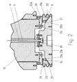
- power transmission system consists essentially of a hydraulic cylinder 1, which has a piston 10 which can be acted upon with hydraulic fluid and a pressure bearing 2 in operative contact with the piston.
- a first seal 23 is provided between the first and second sliding surfaces 20a, 22a, and a second seal 24 is provided between the third and fourth sliding surfaces 22b, 21a.
- a pressure space 25 is thereby formed which is delimited by the first and second pressure elements 20, 21, the intermediate element 22 and a part of the end face of the piston 10 facing the thrust bearing. The seal to the outside in the region of the sliding surfaces via the seals 23, 24th
- the pressure chamber 25 is connected via one or more bores 11 formed in the piston with the hydraulic fluid acted upon side of the piston 10 in connection. In this way, hydraulic fluid enters the pressure chamber 25 and there causes Auseindermotherbone of the first and second pressure element 20, 21, whereby the pressure acting on the sliding surfaces pressure corresponding to the effective pressure surfaces is reduced.
- the effective pressure surfaces are formed by the diameter (d) of the annular seals 23 and 24 according to the formula (d / 2) 2 * ⁇ .
- a coupling rod 3 is further provided, which connects the thrust bearing 2 with the hydraulic cylinder 1, wherein the coupling rod is articulated both in the region of the thrust bearing and in the region of the piston to the sliding movement to ensure the thrust bearing in the region of the first and second or third and fourth sliding surface.
- the coupling rod 3 in the region of the thrust bearing on the second pressure element 21 via a bearing 30 and in the region facing away from the thrust bearing 2 end face 12 of the piston in a bearing 31 is articulated.
- the first and second sliding surfaces 20a, 22a are aligned transversely to the direction of movement of the piston and form a plane sliding surface.
- a sliding surface is spherical or spherical and the other sliding surface is formed as a correspondingly complementary counter surface.
- the third and fourth sliding surface thus allow a pivoting movement of the thrust bearing.
- the pivot radius of the thrust bearing is turned off on the pivoting movement of the associated with the power transmission system power arm.
- the pressure surfaces defined by the seals 23, 24 should be as high as 80 to 95% of the cross-sectional area of the piston 10. The lateral forces are then reduced to a corresponding extent, so that the sliding surfaces are acted upon only with 5 to 20% of the pressure. A certain pressure in the area of the sliding surfaces seems expedient so that the thrust bearing does not lift off and float. Also the escape of hydraulic fluid can then be avoided more easily.
- the pressure surfaces formed by the seals 23, 24 could be up to 100 percent or more of the piston cross-sectional area. In the experiments on which the invention is based, however, it has been shown that a value of the pressure surfaces formed by the seals 23, 24 in the range from 75 to 99%, preferably between 80 and 95%, are ideal for highly dynamic applications.
- the residual pressure with which the sliding surfaces are pressed against each other is expediently transmitted via guide or support rings 26, 27, which are characterized by a particularly low coefficient of friction.
- the support ring 26 is therefore disposed between the first and second sliding surfaces 20 a, 22 a outside the seal 23.
- the support ring 27 is located outside the seal 24 between the third and fourth sliding surface 22b and 21a.
- the thrust bearing is further surrounded by an outer wall 8 which is formed so flexible that it does not hinder the movement of the thrust bearing.
- This outer wall may also have a leakage port to return leaking hydraulic fluid to the reservoir.
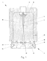
- roller mill shown schematically consists essentially of a grinding roller 4 and a rotatable grinding table 5. Furthermore, a power arm 6 is provided, which is supported pivotably and rotationally fixed in a bearing 7 designed as a fixed bearing, wherein the grinding roller 4 is rotatably mounted at the opposite end of the power arm. Further, a Power transmission system according to the above description, which acts with its hydraulic cylinder 1 and its thrust bearing 2 in a central region of the power arm 6 on this.
- the hydraulic cylinder 1 In order to adjust the pressure exerted by the grinding roller 4 on the grinding table 5 pressure, the hydraulic cylinder 1 is acted upon by a corresponding hydraulic pressure. The pivotal movement of the power arm 6 is compensated by the thrust bearing 2, so that the hydraulic cylinder 1 can be arranged fixed.
- a plunger cylinder is suitable for the hydraulic cylinder.
- the power transmission system acts in a central region between the grinding roller 4 and bearing 7 on the power arm 6.
- the positions of bearing and power transmission system are reversed.
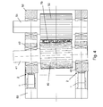
- FIG. 4 illustrates and represents a roller press with two counter-rotating grinding rollers 40, 50.
- the grinding roller 50 is mounted with a Mahlrollenachse 51 in a fixed bearing 52, while the grinding roller 40 is mounted with its Mahlrollenachse 41 in a floating bearing 42.
- the grinding stock 70 to be comminuted is fed to the gap formed between the grinding rollers 40, 50 and comminuted between the rollers.
- a power transmission system according to the above description is provided, which is supported with its hydraulic cylinder 1 on a power frame 60 and is in operative contact with its thrust bearing 2 with the movable bearing 42.
- the Mahlrollenachsen are mounted in two bearings, so that two power transmission systems are provided.
- the power transmission system in a roller press is therefore also suitable for compensating for an adjustment of the two grinding rollers during operation.
- Hydraulic cylinders and thrust bearings can therefore be designed for the reduced lateral forces, resulting in a more compact design and can reduce the cost of manufacturing.
Landscapes
- Engineering & Computer Science (AREA)
- Food Science & Technology (AREA)
- Physics & Mathematics (AREA)
- Fluid Mechanics (AREA)
- Mechanical Engineering (AREA)
- General Engineering & Computer Science (AREA)
- Crushing And Grinding (AREA)
- Vehicle Body Suspensions (AREA)
- Devices For Conveying Motion By Means Of Endless Flexible Members (AREA)
- Support Of The Bearing (AREA)
- Actuator (AREA)
- Friction Gearing (AREA)
Applications Claiming Priority (2)
| Application Number | Priority Date | Filing Date | Title |
|---|---|---|---|
| DE102008010652A DE102008010652B3 (de) | 2008-02-22 | 2008-02-22 | Kraftübertragungssystem und Rollenmühle |
| PCT/EP2009/051977 WO2009103762A1 (de) | 2008-02-22 | 2009-02-19 | Kraftübertragungssystem mit einem hydraulikzylinder und einem drucklager |
Publications (2)
| Publication Number | Publication Date |
|---|---|
| EP2111510A1 EP2111510A1 (de) | 2009-10-28 |
| EP2111510B1 true EP2111510B1 (de) | 2011-04-27 |
Family
ID=40707890
Family Applications (1)
| Application Number | Title | Priority Date | Filing Date |
|---|---|---|---|
| EP09707109A Active EP2111510B1 (de) | 2008-02-22 | 2009-02-19 | Kraftübertragungssystem mit einem hydraulikzylinder und einem drucklager |
Country Status (8)
| Country | Link |
|---|---|
| US (1) | US8398008B2 (enExample) |
| EP (1) | EP2111510B1 (enExample) |
| JP (1) | JP5313269B2 (enExample) |
| CN (1) | CN101946097B (enExample) |
| AT (1) | ATE507398T1 (enExample) |
| DE (2) | DE102008010652B3 (enExample) |
| DK (1) | DK2111510T3 (enExample) |
| WO (1) | WO2009103762A1 (enExample) |
Families Citing this family (7)
| Publication number | Priority date | Publication date | Assignee | Title |
|---|---|---|---|---|
| US9856892B2 (en) | 2013-04-12 | 2018-01-02 | Spx Flow, Inc. | Cylinder having a floating piston, swivel cap, and lubricated rod |
| CN105247225B (zh) * | 2013-04-12 | 2017-11-17 | Spx流动有限公司 | 旋转帽 |
| US10107314B2 (en) | 2013-04-12 | 2018-10-23 | Spx Flow, Inc. | Cylinder having a floating piston, low profile swivel cap, and lubricated rod |
| US10100928B2 (en) | 2014-07-22 | 2018-10-16 | Spx Flow, Inc. | Floating piston |
| CN105057024A (zh) * | 2015-07-20 | 2015-11-18 | 成都大宏立机器股份有限公司 | 高压辊磨机球头传力机构 |
| CN110173478B (zh) * | 2019-06-05 | 2020-05-05 | 浙江厚达智能科技股份有限公司 | 中药生产用驱动机构 |
| PL4103328T3 (pl) | 2020-02-14 | 2024-05-06 | thyssenkrupp Polysius GmbH | Młyn walcowy z urządzeniem synchronizującym |
Family Cites Families (19)
| Publication number | Priority date | Publication date | Assignee | Title |
|---|---|---|---|---|
| JPS5858116U (ja) * | 1981-10-16 | 1983-04-20 | 株式会社日立製作所 | 自動調心形すべり軸受装置 |
| JPS5993513A (ja) * | 1982-11-17 | 1984-05-30 | Mitsubishi Heavy Ind Ltd | チルチングパツドジヤ−ナル軸受 |
| DE3718781A1 (de) * | 1987-06-04 | 1988-12-15 | Krupp Polysius Ag | Rollenmuehle |
| DE3801728C2 (de) * | 1988-01-21 | 1998-07-02 | Krupp Polysius Ag | Rollenmühle |
| CH678091A5 (enExample) * | 1988-05-10 | 1991-07-31 | Von Roll Hydraulik | |
| CN2060978U (zh) * | 1989-04-28 | 1990-08-29 | 杨有建 | 旋转柱塞式食品挤出机 |
| JP2651875B2 (ja) * | 1990-11-22 | 1997-09-10 | 宇部興産株式会社 | ロールプレス |
| CN2230658Y (zh) * | 1995-07-25 | 1996-07-10 | 哈尔滨粮油机械厂 | 液压对辊轧胚机 |
| JP3354816B2 (ja) * | 1996-12-05 | 2002-12-09 | 三菱重工業株式会社 | 球面座付き静圧滑り軸受 |
| JP3703610B2 (ja) * | 1997-08-06 | 2005-10-05 | カヤバ工業株式会社 | アキシャルピストンポンプまたはモータ |
| JP3286241B2 (ja) * | 1998-02-24 | 2002-05-27 | 株式会社栗本鐵工所 | 竪型ミル |
| JP2000312832A (ja) * | 1999-04-30 | 2000-11-14 | Ishikawajima Harima Heavy Ind Co Ltd | 竪型ミル |
| DE29913762U1 (de) * | 1999-08-06 | 2000-03-23 | IBS Ingenieurberatung Schlutz GmbH, 45770 Marl | PTFE-Beschichtung zur Herstellung eines hydraulischen Zylinders |
| DE19954577C1 (de) * | 1999-11-12 | 2001-06-21 | Hyco Pacoma Gmbh | Liftzylindereinheit für eine Hebebühne |
| FI20002487A0 (fi) * | 2000-11-14 | 2000-11-14 | Valmet Corp | Ppaeri-/kartonkikoneen tai jälkikäsittelykoneen telan ulkopuolinen liukulaakerointi |
| JP4665308B2 (ja) * | 2000-11-28 | 2011-04-06 | 株式会社Ihi | 竪型ミル |
| CN2666718Y (zh) * | 2003-10-31 | 2004-12-29 | 王宗成 | 由液力驱控的离合器组片式防滑差速器 |
| CN100381236C (zh) * | 2005-12-22 | 2008-04-16 | 重庆大学 | 非回转式高速通孔动力卡盘装置 |
| DE102006058012A1 (de) * | 2006-12-08 | 2008-06-19 | Polysius Ag | Rollenmühle |
-
2008
- 2008-02-22 DE DE102008010652A patent/DE102008010652B3/de active Active
-
2009
- 2009-02-19 WO PCT/EP2009/051977 patent/WO2009103762A1/de not_active Ceased
- 2009-02-19 JP JP2010547179A patent/JP5313269B2/ja not_active Expired - Fee Related
- 2009-02-19 AT AT09707109T patent/ATE507398T1/de active
- 2009-02-19 DE DE502009000572T patent/DE502009000572D1/de active Active
- 2009-02-19 CN CN200980105028.9A patent/CN101946097B/zh active Active
- 2009-02-19 DK DK09707109.6T patent/DK2111510T3/da active
- 2009-02-19 US US12/918,229 patent/US8398008B2/en active Active
- 2009-02-19 EP EP09707109A patent/EP2111510B1/de active Active
Also Published As
| Publication number | Publication date |
|---|---|
| EP2111510A1 (de) | 2009-10-28 |
| DE102008010652B3 (de) | 2009-11-05 |
| JP2011512253A (ja) | 2011-04-21 |
| JP5313269B2 (ja) | 2013-10-09 |
| DK2111510T3 (da) | 2011-08-01 |
| CN101946097B (zh) | 2013-08-07 |
| ATE507398T1 (de) | 2011-05-15 |
| CN101946097A (zh) | 2011-01-12 |
| US20110006144A1 (en) | 2011-01-13 |
| US8398008B2 (en) | 2013-03-19 |
| DE502009000572D1 (de) | 2011-06-09 |
| WO2009103762A1 (de) | 2009-08-27 |
Similar Documents
| Publication | Publication Date | Title |
|---|---|---|
| EP2111510B1 (de) | Kraftübertragungssystem mit einem hydraulikzylinder und einem drucklager | |
| EP1566543B1 (de) | Elastomerlagerung mit regulierbarer Steifigkeit | |
| EP2081689B1 (de) | Rollenmühle | |
| DE2942002A1 (de) | Druckbehandlungswalze | |
| DE102009054794B4 (de) | Radiale Drehdurchführung und Buchse hierfür | |
| EP1902820A2 (de) | Vorrichtung zum Schneiden und/oder Prägen eines Zuschnitts oder einer Materialbahn | |
| WO1982000165A1 (fr) | Cylindre de compression, dont la flexion est reglable | |
| DE8915859U1 (de) | Vorrichtung zum Einleiten einer Hubbewegung in einer Hubmechanik | |
| DE2919105A1 (de) | Walzwerk | |
| DE2623492A1 (de) | Drucksteuereinrichtung fuer arbeitsvorrichtungen mit walzen | |
| EP2858767B1 (de) | Walzenanordnung | |
| DE102010016472C5 (de) | Wälzmühle | |
| DE2540269B2 (de) | Einstellbare Stützvorrichtung für die Loswalze einer Walzenmühle | |
| DE3025799A1 (de) | Presswalze, deren durchbiegung einstellbar ist | |
| DE3329595C2 (de) | Walze für einen Folienziehkalander | |
| DE2650692B2 (de) | Kupplungseinrichtung einer Gelenkwelle für Walzwerksantriebe | |
| DE2850415B1 (de) | Durchbiegungseinstellwalze | |
| AT392661B (de) | Presswalze, deren durchbiegung einstellbar ist | |
| EP1687104B1 (de) | Anstellzylinder in walzgerüsten, unter anderem in vertikal-stauchgerüsten | |
| DE10121820B4 (de) | Durchbiegungskompensierte Walze für eine Papier/Karton- oder Finishingmaschine | |
| DE102006043288B4 (de) | Vorrichtung und Verfahren zum Prägen einer Materialbahn | |
| EP3927997B1 (de) | Kugelgewindetrieb mit verdrehsicherung | |
| EP3706928B1 (de) | Walzgerüst mit einer dichtung gegen einen austritt von schmiermittel | |
| EP1321180A2 (de) | Innenmischer | |
| WO2010034501A1 (de) | Kreuzgelenkanordnung für eine gelenkwelle |
Legal Events
| Date | Code | Title | Description |
|---|---|---|---|
| PUAI | Public reference made under article 153(3) epc to a published international application that has entered the european phase |
Free format text: ORIGINAL CODE: 0009012 |
|
| 17P | Request for examination filed |
Effective date: 20090810 |
|
| AK | Designated contracting states |
Kind code of ref document: A1 Designated state(s): AT BE BG CH CY CZ DE DK EE ES FI FR GB GR HR HU IE IS IT LI LT LU LV MC MK MT NL NO PL PT RO SE SI SK TR |
|
| GRAP | Despatch of communication of intention to grant a patent |
Free format text: ORIGINAL CODE: EPIDOSNIGR1 |
|
| GRAS | Grant fee paid |
Free format text: ORIGINAL CODE: EPIDOSNIGR3 |
|
| GRAA | (expected) grant |
Free format text: ORIGINAL CODE: 0009210 |
|
| AK | Designated contracting states |
Kind code of ref document: B1 Designated state(s): AT BE BG CH CY CZ DE DK EE ES FI FR GB GR HR HU IE IS IT LI LT LU LV MC MK MT NL NO PL PT RO SE SI SK TR |
|
| REG | Reference to a national code |
Ref country code: GB Ref legal event code: FG4D Free format text: NOT ENGLISH |
|
| REG | Reference to a national code |
Ref country code: CH Ref legal event code: EP |
|
| REG | Reference to a national code |
Ref country code: IE Ref legal event code: FG4D Free format text: LANGUAGE OF EP DOCUMENT: GERMAN |
|
| REF | Corresponds to: |
Ref document number: 502009000572 Country of ref document: DE Date of ref document: 20110609 Kind code of ref document: P |
|
| REG | Reference to a national code |
Ref country code: DE Ref legal event code: R096 Ref document number: 502009000572 Country of ref document: DE Effective date: 20110609 |
|
| REG | Reference to a national code |
Ref country code: DK Ref legal event code: T3 |
|
| REG | Reference to a national code |
Ref country code: NL Ref legal event code: VDEP Effective date: 20110427 |
|
| RAP2 | Party data changed (patent owner data changed or rights of a patent transferred) |
Owner name: THYSSENKRUPP POLYSIUS AG |
|
| LTIE | Lt: invalidation of european patent or patent extension |
Effective date: 20110427 |
|
| PG25 | Lapsed in a contracting state [announced via postgrant information from national office to epo] |
Ref country code: NO Free format text: LAPSE BECAUSE OF FAILURE TO SUBMIT A TRANSLATION OF THE DESCRIPTION OR TO PAY THE FEE WITHIN THE PRESCRIBED TIME-LIMIT Effective date: 20110727 Ref country code: SE Free format text: LAPSE BECAUSE OF FAILURE TO SUBMIT A TRANSLATION OF THE DESCRIPTION OR TO PAY THE FEE WITHIN THE PRESCRIBED TIME-LIMIT Effective date: 20110427 Ref country code: LT Free format text: LAPSE BECAUSE OF FAILURE TO SUBMIT A TRANSLATION OF THE DESCRIPTION OR TO PAY THE FEE WITHIN THE PRESCRIBED TIME-LIMIT Effective date: 20110427 Ref country code: HR Free format text: LAPSE BECAUSE OF FAILURE TO SUBMIT A TRANSLATION OF THE DESCRIPTION OR TO PAY THE FEE WITHIN THE PRESCRIBED TIME-LIMIT Effective date: 20110427 Ref country code: PT Free format text: LAPSE BECAUSE OF FAILURE TO SUBMIT A TRANSLATION OF THE DESCRIPTION OR TO PAY THE FEE WITHIN THE PRESCRIBED TIME-LIMIT Effective date: 20110829 |
|
| REG | Reference to a national code |
Ref country code: IE Ref legal event code: FD4D |
|
| PG25 | Lapsed in a contracting state [announced via postgrant information from national office to epo] |
Ref country code: CY Free format text: LAPSE BECAUSE OF FAILURE TO SUBMIT A TRANSLATION OF THE DESCRIPTION OR TO PAY THE FEE WITHIN THE PRESCRIBED TIME-LIMIT Effective date: 20110427 Ref country code: IS Free format text: LAPSE BECAUSE OF FAILURE TO SUBMIT A TRANSLATION OF THE DESCRIPTION OR TO PAY THE FEE WITHIN THE PRESCRIBED TIME-LIMIT Effective date: 20110827 Ref country code: SI Free format text: LAPSE BECAUSE OF FAILURE TO SUBMIT A TRANSLATION OF THE DESCRIPTION OR TO PAY THE FEE WITHIN THE PRESCRIBED TIME-LIMIT Effective date: 20110427 Ref country code: FI Free format text: LAPSE BECAUSE OF FAILURE TO SUBMIT A TRANSLATION OF THE DESCRIPTION OR TO PAY THE FEE WITHIN THE PRESCRIBED TIME-LIMIT Effective date: 20110427 Ref country code: GR Free format text: LAPSE BECAUSE OF FAILURE TO SUBMIT A TRANSLATION OF THE DESCRIPTION OR TO PAY THE FEE WITHIN THE PRESCRIBED TIME-LIMIT Effective date: 20110728 Ref country code: ES Free format text: LAPSE BECAUSE OF FAILURE TO SUBMIT A TRANSLATION OF THE DESCRIPTION OR TO PAY THE FEE WITHIN THE PRESCRIBED TIME-LIMIT Effective date: 20110807 Ref country code: LV Free format text: LAPSE BECAUSE OF FAILURE TO SUBMIT A TRANSLATION OF THE DESCRIPTION OR TO PAY THE FEE WITHIN THE PRESCRIBED TIME-LIMIT Effective date: 20110427 |
|
| PG25 | Lapsed in a contracting state [announced via postgrant information from national office to epo] |
Ref country code: NL Free format text: LAPSE BECAUSE OF FAILURE TO SUBMIT A TRANSLATION OF THE DESCRIPTION OR TO PAY THE FEE WITHIN THE PRESCRIBED TIME-LIMIT Effective date: 20110427 |
|
| REG | Reference to a national code |
Ref country code: DE Ref legal event code: R082 Ref document number: 502009000572 Country of ref document: DE Representative=s name: RA U. PA VOLKMAR TETZNER; PA MICHAEL TETZNER; , DE |
|
| PG25 | Lapsed in a contracting state [announced via postgrant information from national office to epo] |
Ref country code: EE Free format text: LAPSE BECAUSE OF FAILURE TO SUBMIT A TRANSLATION OF THE DESCRIPTION OR TO PAY THE FEE WITHIN THE PRESCRIBED TIME-LIMIT Effective date: 20110427 Ref country code: IE Free format text: LAPSE BECAUSE OF FAILURE TO SUBMIT A TRANSLATION OF THE DESCRIPTION OR TO PAY THE FEE WITHIN THE PRESCRIBED TIME-LIMIT Effective date: 20110427 |
|
| PG25 | Lapsed in a contracting state [announced via postgrant information from national office to epo] |
Ref country code: PL Free format text: LAPSE BECAUSE OF FAILURE TO SUBMIT A TRANSLATION OF THE DESCRIPTION OR TO PAY THE FEE WITHIN THE PRESCRIBED TIME-LIMIT Effective date: 20110427 Ref country code: SK Free format text: LAPSE BECAUSE OF FAILURE TO SUBMIT A TRANSLATION OF THE DESCRIPTION OR TO PAY THE FEE WITHIN THE PRESCRIBED TIME-LIMIT Effective date: 20110427 |
|
| PLBE | No opposition filed within time limit |
Free format text: ORIGINAL CODE: 0009261 |
|
| STAA | Information on the status of an ep patent application or granted ep patent |
Free format text: STATUS: NO OPPOSITION FILED WITHIN TIME LIMIT |
|
| REG | Reference to a national code |
Ref country code: DE Ref legal event code: R081 Ref document number: 502009000572 Country of ref document: DE Owner name: THYSSENKRUPP RESOURCE TECHNOLOGIES AG, DE Free format text: FORMER OWNER: POLYSIUS AG, 59269 BECKUM, DE Effective date: 20120118 Ref country code: DE Ref legal event code: R082 Ref document number: 502009000572 Country of ref document: DE Representative=s name: RECHTSANW. UND PAT.-ANW. DR.-ING. DR.JUR. VOLK, DE Effective date: 20120118 Ref country code: DE Ref legal event code: R081 Ref document number: 502009000572 Country of ref document: DE Owner name: THYSSENKRUPP RESOURCE TECHNOLOGIES GMBH, DE Free format text: FORMER OWNER: POLYSIUS AG, 59269 BECKUM, DE Effective date: 20120118 Ref country code: DE Ref legal event code: R082 Ref document number: 502009000572 Country of ref document: DE Representative=s name: TETZNER & PARTNER MBB PATENT- UND RECHTSANWAEL, DE Effective date: 20120118 Ref country code: DE Ref legal event code: R081 Ref document number: 502009000572 Country of ref document: DE Owner name: THYSSENKRUPP INDUSTRIAL SOLUTIONS AG, DE Free format text: FORMER OWNER: POLYSIUS AG, 59269 BECKUM, DE Effective date: 20120118 |
|
| 26N | No opposition filed |
Effective date: 20120130 |
|
| REG | Reference to a national code |
Ref country code: DE Ref legal event code: R097 Ref document number: 502009000572 Country of ref document: DE Effective date: 20120130 |
|
| PG25 | Lapsed in a contracting state [announced via postgrant information from national office to epo] |
Ref country code: IT Free format text: LAPSE BECAUSE OF FAILURE TO SUBMIT A TRANSLATION OF THE DESCRIPTION OR TO PAY THE FEE WITHIN THE PRESCRIBED TIME-LIMIT Effective date: 20110427 |
|
| BERE | Be: lapsed |
Owner name: POLYSIUS A.G. Effective date: 20120228 |
|
| PG25 | Lapsed in a contracting state [announced via postgrant information from national office to epo] |
Ref country code: MC Free format text: LAPSE BECAUSE OF NON-PAYMENT OF DUE FEES Effective date: 20120229 |
|
| PG25 | Lapsed in a contracting state [announced via postgrant information from national office to epo] |
Ref country code: BE Free format text: LAPSE BECAUSE OF NON-PAYMENT OF DUE FEES Effective date: 20120228 |
|
| PG25 | Lapsed in a contracting state [announced via postgrant information from national office to epo] |
Ref country code: MK Free format text: LAPSE BECAUSE OF FAILURE TO SUBMIT A TRANSLATION OF THE DESCRIPTION OR TO PAY THE FEE WITHIN THE PRESCRIBED TIME-LIMIT Effective date: 20110427 |
|
| REG | Reference to a national code |
Ref country code: DE Ref legal event code: R082 Ref document number: 502009000572 Country of ref document: DE Representative=s name: RECHTSANW. UND PAT.-ANW. DR.-ING. DR.JUR. VOLK, DE |
|
| PG25 | Lapsed in a contracting state [announced via postgrant information from national office to epo] |
Ref country code: BG Free format text: LAPSE BECAUSE OF FAILURE TO SUBMIT A TRANSLATION OF THE DESCRIPTION OR TO PAY THE FEE WITHIN THE PRESCRIBED TIME-LIMIT Effective date: 20110727 |
|
| PG25 | Lapsed in a contracting state [announced via postgrant information from national office to epo] |
Ref country code: MT Free format text: LAPSE BECAUSE OF FAILURE TO SUBMIT A TRANSLATION OF THE DESCRIPTION OR TO PAY THE FEE WITHIN THE PRESCRIBED TIME-LIMIT Effective date: 20110427 |
|
| REG | Reference to a national code |
Ref country code: DE Ref legal event code: R082 Ref document number: 502009000572 Country of ref document: DE Representative=s name: RECHTSANW. UND PAT.-ANW. DR.-ING. DR.JUR. VOLK, DE Effective date: 20130626 Ref country code: DE Ref legal event code: R081 Ref document number: 502009000572 Country of ref document: DE Owner name: THYSSENKRUPP RESOURCE TECHNOLOGIES GMBH, DE Free format text: FORMER OWNER: THYSSENKRUPP RESOURCE TECHNOLOGIES AG, 59269 BECKUM, DE Effective date: 20130808 Ref country code: DE Ref legal event code: R081 Ref document number: 502009000572 Country of ref document: DE Owner name: THYSSENKRUPP RESOURCE TECHNOLOGIES GMBH, DE Free format text: FORMER OWNER: THYSSENKRUPP POLYSIUS AG, 59269 BECKUM, DE Effective date: 20130626 Ref country code: DE Ref legal event code: R082 Ref document number: 502009000572 Country of ref document: DE Representative=s name: RECHTSANW. UND PAT.-ANW. DR.-ING. DR.JUR. VOLK, DE Effective date: 20130808 Ref country code: DE Ref legal event code: R082 Ref document number: 502009000572 Country of ref document: DE Representative=s name: TETZNER & PARTNER MBB PATENT- UND RECHTSANWAEL, DE Effective date: 20130808 Ref country code: DE Ref legal event code: R082 Ref document number: 502009000572 Country of ref document: DE Representative=s name: TETZNER & PARTNER MBB PATENT- UND RECHTSANWAEL, DE Effective date: 20130626 Ref country code: DE Ref legal event code: R081 Ref document number: 502009000572 Country of ref document: DE Owner name: THYSSENKRUPP INDUSTRIAL SOLUTIONS AG, DE Free format text: FORMER OWNER: THYSSENKRUPP POLYSIUS AG, 59269 BECKUM, DE Effective date: 20130626 Ref country code: DE Ref legal event code: R081 Ref document number: 502009000572 Country of ref document: DE Owner name: THYSSENKRUPP INDUSTRIAL SOLUTIONS AG, DE Free format text: FORMER OWNER: THYSSENKRUPP RESOURCE TECHNOLOGIES AG, 59269 BECKUM, DE Effective date: 20130808 |
|
| REG | Reference to a national code |
Ref country code: CH Ref legal event code: PL |
|
| GBPC | Gb: european patent ceased through non-payment of renewal fee |
Effective date: 20130219 |
|
| PG25 | Lapsed in a contracting state [announced via postgrant information from national office to epo] |
Ref country code: CH Free format text: LAPSE BECAUSE OF NON-PAYMENT OF DUE FEES Effective date: 20130228 Ref country code: LI Free format text: LAPSE BECAUSE OF NON-PAYMENT OF DUE FEES Effective date: 20130228 |
|
| PG25 | Lapsed in a contracting state [announced via postgrant information from national office to epo] |
Ref country code: GB Free format text: LAPSE BECAUSE OF NON-PAYMENT OF DUE FEES Effective date: 20130219 |
|
| PG25 | Lapsed in a contracting state [announced via postgrant information from national office to epo] |
Ref country code: TR Free format text: LAPSE BECAUSE OF FAILURE TO SUBMIT A TRANSLATION OF THE DESCRIPTION OR TO PAY THE FEE WITHIN THE PRESCRIBED TIME-LIMIT Effective date: 20110427 |
|
| REG | Reference to a national code |
Ref country code: DE Ref legal event code: R082 Ref document number: 502009000572 Country of ref document: DE Representative=s name: TETZNER & PARTNER MBB PATENT- UND RECHTSANWAEL, DE |
|
| PG25 | Lapsed in a contracting state [announced via postgrant information from national office to epo] |
Ref country code: LU Free format text: LAPSE BECAUSE OF NON-PAYMENT OF DUE FEES Effective date: 20120219 |
|
| REG | Reference to a national code |
Ref country code: DE Ref legal event code: R082 Ref document number: 502009000572 Country of ref document: DE Representative=s name: TETZNER & PARTNER MBB PATENT- UND RECHTSANWAEL, DE |
|
| PG25 | Lapsed in a contracting state [announced via postgrant information from national office to epo] |
Ref country code: HU Free format text: LAPSE BECAUSE OF FAILURE TO SUBMIT A TRANSLATION OF THE DESCRIPTION OR TO PAY THE FEE WITHIN THE PRESCRIBED TIME-LIMIT Effective date: 20090219 |
|
| REG | Reference to a national code |
Ref country code: DE Ref legal event code: R082 Ref document number: 502009000572 Country of ref document: DE Representative=s name: TETZNER & PARTNER MBB PATENT- UND RECHTSANWAEL, DE Effective date: 20140729 Ref country code: DE Ref legal event code: R082 Ref document number: 502009000572 Country of ref document: DE Representative=s name: TETZNER & PARTNER MBB PATENT- UND RECHTSANWAEL, DE Effective date: 20140519 Ref country code: DE Ref legal event code: R081 Ref document number: 502009000572 Country of ref document: DE Owner name: THYSSENKRUPP INDUSTRIAL SOLUTIONS AG, DE Free format text: FORMER OWNER: THYSSENKRUPP RESOURCE TECHNOLOGIES GMBH, 59269 BECKUM, DE Effective date: 20140729 |
|
| REG | Reference to a national code |
Ref country code: FR Ref legal event code: PLFP Year of fee payment: 8 |
|
| REG | Reference to a national code |
Ref country code: FR Ref legal event code: PLFP Year of fee payment: 9 |
|
| REG | Reference to a national code |
Ref country code: FR Ref legal event code: PLFP Year of fee payment: 10 |
|
| REG | Reference to a national code |
Ref country code: DE Ref legal event code: R082 Ref document number: 502009000572 Country of ref document: DE Representative=s name: TETZNER & PARTNER MBB PATENT- UND RECHTSANWAEL, DE Ref country code: DE Ref legal event code: R081 Ref document number: 502009000572 Country of ref document: DE Owner name: THYSSENKRUPP INDUSTRIAL SOLUTIONS AG, DE Free format text: FORMER OWNER: THYSSENKRUPP INDUSTRIAL SOLUTIONS AG, 45143 ESSEN, DE |
|
| PGFP | Annual fee paid to national office [announced via postgrant information from national office to epo] |
Ref country code: AT Payment date: 20190219 Year of fee payment: 11 |
|
| PGFP | Annual fee paid to national office [announced via postgrant information from national office to epo] |
Ref country code: DE Payment date: 20200219 Year of fee payment: 12 |
|
| PGFP | Annual fee paid to national office [announced via postgrant information from national office to epo] |
Ref country code: CZ Payment date: 20200214 Year of fee payment: 12 |
|
| PGFP | Annual fee paid to national office [announced via postgrant information from national office to epo] |
Ref country code: FR Payment date: 20200219 Year of fee payment: 12 |
|
| REG | Reference to a national code |
Ref country code: AT Ref legal event code: MM01 Ref document number: 507398 Country of ref document: AT Kind code of ref document: T Effective date: 20200219 |
|
| PG25 | Lapsed in a contracting state [announced via postgrant information from national office to epo] |
Ref country code: AT Free format text: LAPSE BECAUSE OF NON-PAYMENT OF DUE FEES Effective date: 20200219 |
|
| REG | Reference to a national code |
Ref country code: DE Ref legal event code: R119 Ref document number: 502009000572 Country of ref document: DE |
|
| PG25 | Lapsed in a contracting state [announced via postgrant information from national office to epo] |
Ref country code: CZ Free format text: LAPSE BECAUSE OF NON-PAYMENT OF DUE FEES Effective date: 20210219 |
|
| PG25 | Lapsed in a contracting state [announced via postgrant information from national office to epo] |
Ref country code: DE Free format text: LAPSE BECAUSE OF NON-PAYMENT OF DUE FEES Effective date: 20210901 Ref country code: FR Free format text: LAPSE BECAUSE OF NON-PAYMENT OF DUE FEES Effective date: 20210228 |
|
| PGFP | Annual fee paid to national office [announced via postgrant information from national office to epo] |
Ref country code: DK Payment date: 20240223 Year of fee payment: 16 |
|
| REG | Reference to a national code |
Ref country code: DK Ref legal event code: EBP Effective date: 20250228 |