EP3927997B1 - Kugelgewindetrieb mit verdrehsicherung - Google Patents
Kugelgewindetrieb mit verdrehsicherung Download PDFInfo
- Publication number
- EP3927997B1 EP3927997B1 EP20702981.0A EP20702981A EP3927997B1 EP 3927997 B1 EP3927997 B1 EP 3927997B1 EP 20702981 A EP20702981 A EP 20702981A EP 3927997 B1 EP3927997 B1 EP 3927997B1
- Authority
- EP
- European Patent Office
- Prior art keywords
- spindle
- movement
- groove
- longitudinal direction
- guide element
- Prior art date
- Legal status (The legal status is an assumption and is not a legal conclusion. Google has not performed a legal analysis and makes no representation as to the accuracy of the status listed.)
- Active
Links
Images
Classifications
-
- F—MECHANICAL ENGINEERING; LIGHTING; HEATING; WEAPONS; BLASTING
- F16—ENGINEERING ELEMENTS AND UNITS; GENERAL MEASURES FOR PRODUCING AND MAINTAINING EFFECTIVE FUNCTIONING OF MACHINES OR INSTALLATIONS; THERMAL INSULATION IN GENERAL
- F16H—GEARING
- F16H25/00—Gearings comprising primarily only cams, cam-followers and screw-and-nut mechanisms
- F16H25/18—Gearings comprising primarily only cams, cam-followers and screw-and-nut mechanisms for conveying or interconverting oscillating or reciprocating motions
- F16H25/20—Screw mechanisms
- F16H25/24—Elements essential to such mechanisms, e.g. screws, nuts
- F16H25/2454—Brakes; Rotational locks
-
- F—MECHANICAL ENGINEERING; LIGHTING; HEATING; WEAPONS; BLASTING
- F16—ENGINEERING ELEMENTS AND UNITS; GENERAL MEASURES FOR PRODUCING AND MAINTAINING EFFECTIVE FUNCTIONING OF MACHINES OR INSTALLATIONS; THERMAL INSULATION IN GENERAL
- F16H—GEARING
- F16H25/00—Gearings comprising primarily only cams, cam-followers and screw-and-nut mechanisms
- F16H25/18—Gearings comprising primarily only cams, cam-followers and screw-and-nut mechanisms for conveying or interconverting oscillating or reciprocating motions
- F16H25/20—Screw mechanisms
- F16H25/22—Screw mechanisms with balls, rollers, or similar members between the co-operating parts; Elements essential to the use of such members
- F16H25/2204—Screw mechanisms with balls, rollers, or similar members between the co-operating parts; Elements essential to the use of such members with balls
-
- F—MECHANICAL ENGINEERING; LIGHTING; HEATING; WEAPONS; BLASTING
- F16—ENGINEERING ELEMENTS AND UNITS; GENERAL MEASURES FOR PRODUCING AND MAINTAINING EFFECTIVE FUNCTIONING OF MACHINES OR INSTALLATIONS; THERMAL INSULATION IN GENERAL
- F16H—GEARING
- F16H25/00—Gearings comprising primarily only cams, cam-followers and screw-and-nut mechanisms
- F16H25/18—Gearings comprising primarily only cams, cam-followers and screw-and-nut mechanisms for conveying or interconverting oscillating or reciprocating motions
- F16H25/20—Screw mechanisms
- F16H2025/204—Axial sliding means, i.e. for rotary support and axial guiding of nut or screw shaft
Definitions
- the present invention relates to a ball screw drive with an anti-twisting device, in particular for use in an automated manual transmission (AMT) for converting rotary into translatory movement.
- AMT automated manual transmission
- spindle usually consist of a spindle with a grooved profile, balls in the grooved profile and a nut that rotates around the spindle with little friction using the balls.
- the spindle slides on the balls in the grooved profile in its longitudinal direction through the inner diameter of the nut.
- This also has a ball return system that returns balls at points where they would run out of the contact surface between the nut and spindle due to the movement of the nut and spindle to points where balls are needed to reduce friction. In other words, it ensures that there are always balls between the nut and spindle in order to ensure as little friction as possible between the nut and spindle. It must also be ensured that the spindle does not rotate as a result of the rotation of the nut.
- an anti-twisting device on the spindle.
- the anti-twisting device is usually achieved by a positive connection between the spindle and the housing of the ball screw drive.
- the state of the art generally provides a cross bolt in the spindle, which projects beyond the spindle in the radial direction and is in the appropriate elongated grooves in the housing along the direction of actuation. This means that the spindle can move in the longitudinal direction, but its rotational freedom is blocked by the anti-twist device.
- the patent document WO2017/005258 A1 discloses an implementation of an anti-twist device in which a securing element is guided in grooves of a guide sleeve with a closed cross-sectional profile.
- the guide sleeve is designed as a thin sheet and is clamped on one side and free on the opposite side. This allows the guide sleeve to twist slightly in the event of rotation of the securing element, causing it to experience torsion in the longitudinal direction.
- the anti-twisting device of the ball screw drive according to the invention has a securing element that is arranged on a movement element that is configured to move along its longitudinal axis, i.e. in the longitudinal direction, and not to perform any rotational movement.
- the securing element protrudes outward in the radial direction from the surface of the movement element at least at one point.
- the at least one guide element does not have an open degree of freedom along the longitudinal axis of the groove, but at least one open degree of freedom for rotation about an axis parallel to the longitudinal axis of the groove.
- the securing element is arranged at one end or in an end region of the movement element. In this way, a section of the spindle that protrudes in the axial direction can be avoided and an unnecessary increase in the installation space of the device as a whole can be prevented.
- the number of guide elements corresponds to the number of locations at which the at least one Securing element protrudes from the surface of the moving element in the radial direction.
- the cross section of the groove of the at least one guide element perpendicular to the longitudinal axis of the guide element has the same shape as the cross section perpendicular to the longitudinal axis of the movement element through the part of the securing element that protrudes into the groove of the guide element.
- several points of the securing element can protrude into the groove, and several securing elements and guide elements can be provided.
- the anti-twisting device has at least two guide elements, preferably arranged evenly around the movement element, in order to at least halve the force to be absorbed by the at least one guide element for each guide element and thus reduce the wear in each individual guide element.
- a further advantageous embodiment of the securing element is that it is in the form of a bolt.
- the cross section of the at least one securing element has a circular shape perpendicular to the longitudinal axis of the securing element at a point where the securing element protrudes into the groove of the guide element.
- the at least one guide element is rotatably mounted on its end faces or at its ends in the housing.
- Such a mounting prevents any movement of the guide element in the housing, except rotation about an axis that is defined by the mounting and parallel to the longitudinal axis of the This type of design has the advantage that the friction between the guide element and the housing is minimized when the guide element is aligned with the securing element, thus reducing wear on the components involved.
- the at least one guide element is arranged in the recess of the housing in such a way that a movement of the guide element in its longitudinal direction is limited on one side by the stop on the housing and a movement of the guide element in the opposite direction is prevented by a locking ring, so that no movements in the longitudinal direction of the guide element are possible.
- Another advantageous embodiment is one in which the guide element has a symmetrical, preferably circular cross-section perpendicular to its longitudinal axis.
- a circular cross-section can guarantee a small size and simple implementation of the invention.
- the guide element and the recess of the housing in which the guide element is accommodated have the same cross-sectional shape perpendicular to the longitudinal axis of the guide element. Such an embodiment therefore does not require any more installation space than anti-twisting devices according to the state of the art.
- the groove of the at least one guide element has a symmetrical cross-section in the longitudinal direction of the groove.
- the material of the at least one guide element and the material of the at least one securing element result in a material pairing that has low wear and/or low frictional resistance when there is friction between the materials.
- the material of the at least one guide element is preferably made of a hard material such as hard steel. In this way, an increased Wear of the groove and of at least one securing element can be avoided and low maintenance requirements can be ensured.
- an embodiment of the invention is advantageous in which the end of the securing element projects into the groove to such an extent that the point of the securing element which comes into contact with one of the side surfaces of the groove during rotation of the securing element by rotation of the movement element is further away from the surface of the spindle than the center of the cross section of the guide element perpendicular to its longitudinal axis.
- the ball screw according to the invention has a spindle with a groove profile and a defined outer diameter and a nut with a defined inner diameter that is slightly larger than the outer diameter of the spindle. It also contains at least two balls that are arranged between the nut and the spindle in their groove profile to enable low-friction movement between the spindle and the nut.
- the spindle moves in the longitudinal direction when the nut rotates around the spindle.
- the longitudinal axes of the nut and the spindle lie one above the other and the nut rotates around the spindle without moving in the longitudinal direction.
- the ball screw according to the invention is provided with an anti-twisting device, whereby the spindle of the ball screw is the moving element of the anti-twisting device.
- the securing element which is arranged on the spindle, thus engages with its protruding ends in the groove of the guide element arranged opposite the spindle and is guided therein.
- the guide element is arranged in a housing of the spindle as described above.
- Another ball screw according to the invention represents the kinematic reversal of the ball screw explained above.
- the spindle rotates around its own longitudinal axis without moving in the axial direction.
- the nut experiences an axial, i.e. translational, movement, for which its rotation must be prevented in this case.
- the anti-twisting device is therefore on the nut provided, whereby this represents the movement element of the anti-twisting device in this ball screw drive.
- the at least one guide element with the groove in which the securing element is guided is consequently arranged opposite the nut in the housing of the ball screw drive of this embodiment. The securing element can thus be guided in the groove of the guide element during translational movement and rotation of the nut is prevented.
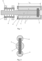
- Fig. 1 shows a schematic diagram of the structure of an embodiment of the ball screw according to the invention with an anti-twist device according to the invention.
- the central components of the ball screw 1 are the spindle 3 and the nut 4 rotating around the longitudinal axis of the spindle.
- Balls are arranged between the nut and the spindle in order to ensure that the nut 4 rotates with as little friction as possible.
- the balls are arranged in a Figure 1 not shown groove profile in the spindle 3.
- the nut 4 is rotatably mounted on its outer diameter by the ball bearings 6, so that a rotational movement of the nut 4 about the spindle 3 is possible, but a movement of the nut 4 in the longitudinal direction of the spindle 3 is prevented.
- the rotational movement of the nut 4 is converted into a translational movement (to the right or left in the plane of the drawing) of the spindle 3 by the balls guided in the groove profile of the spindle 3. Since the balls would migrate out of the area between the nut 4 and the spindle 3 along the groove profile due to the rotational movement of the nut 4 and the resulting translational movement of the spindle 3, the balls must be guided back from one end of the nut 4 to the other end. This is done via a return system within the nut 4 (not shown) that is known in the prior art.
- the anti-twisting device consists of the Figure 1 illustrated embodiment consists of three components. Firstly, at the end of the spindle 3, which is to be understood here as a movement element, a securing element 2 is provided, which is arranged perpendicular to the longitudinal axis of the spindle 3.
- the securing element 2 also has a circular cross-section in a cutting direction perpendicular to the longitudinal axis of the securing element 2. It can therefore be described as a cylindrical bolt that is perpendicular to the longitudinal axis of the spindle 3.
- the bolt protrudes with both ends clearly from the surface of the spindle 3 in a radial direction outwards.
- the end faces of the bolt are designed as flat surfaces in this embodiment.
- the other two components of the anti-twisting device are guide elements 5, which are arranged directly opposite each other, in the drawing plane above and below the spindle 3, parallel to the longitudinal axis of the spindle 3.
- the guide elements 5 also have a circular cross-section and can therefore be described as cylinders with flat end faces.
- the two guide elements 5 On the side facing the spindle 3, the two guide elements 5 have a groove (in Fig. 1 not shown), which each end of the securing element 2.
- the grooves are arranged in the guide elements 5 in such a way that when the spindle 3 moves translationally to the left (in the plane of the drawing), the spindle 3 can be guided via the securing element 2 in the grooves over the entire actuation length L b and rotation of the spindle 3 can be avoided.
- the cross-sectional shapes of the grooves correspond to the ends of the securing element 3 to be guided, so that the cross sections of the grooves are filled as completely as possible by the ends of the securing element 2, without hindering the translational movement of the securing element 2 along the grooves.
- the guide elements 5 are in turn each arranged in a recess of a housing 8 of the ball screw drive 1.
- the recesses and the guide elements 5 have the same cross-sectional shape perpendicular to the longitudinal axis of the guide elements 5.
- the radius of the described cross section of the guide elements 5 is slightly smaller than the radius of the cross sections of the respective recesses.
- a movement in the longitudinal direction is limited on the one hand by the stop of the guide elements 5 on the housing 8 (right side in the plane of the drawing) and on the other hand by a locking ring 9 (left side in the plane of the drawing).
- the guide elements 5 can therefore rotate in their recesses about their longitudinal axes, while a translational movement of the guide elements in the longitudinal direction is not possible.
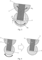
- Fig. 2 shows a cross-sectional view of the embodiment of the ball screw from Fig. 1
- the section runs at the level of the securing element, so that the spindle 3, the securing element 2 and the two guide elements 5 are shown.
- the circular cross sections of the spindle 3 and the two guide elements 5 can be seen.
- the securing element 2 engages with the respective ends in the groove of the guide element 5. In this view, the movement of the spindle and thus of the securing element 2 runs into or out of the drawing plane.
- Fig. 3 shows a detailed view of the cross-sectional view from Figure 2 , whereby only the lower guide element 5 and the lower part of the spindle 3 and the securing element 2. It is pointed out that in order to better explain the principle of the invention, the groove of the guide element 5 has been shown to be significantly larger than the end of the securing element 2, so that a clear play can be seen between the groove and the securing element 2.
- the spindle 3 and thus also the securing element 2 have a slight angle of rotation in relation to the guide element 5. This results from a slight rotation of the spindle 3, which was caused by the torque M s , which in turn acts on the spindle 3 by the rotation of the nut 4. Since the groove has a larger cross-section than the securing element 2 in the area of the groove, the end of the securing element 2 can initially move in the groove. From a certain angle of rotation, the securing element comes into contact with a side surface of the groove (state shown). The contact point of the end of the securing element 2 is located in the drawing plane below the center of the essentially circular cross-section of the guide element 5. This is in Figure 3 by the distance L a between the center of the cross-section of the guide element and the point of contact between the groove and the securing element 2.
- the moment M s is now transferred to the guide element 5. Since this is in the recess of the housing (not shown in Fig. 3 ) can easily move and in particular rotate in the plane of the drawing, the moment M s of the securing element 2 leads to a moment Mf of the guide element 5, which in particular results in a rotation of the guide element 5 in the recess.
- Fig 4 shows the alignment of the guide element 5 as a result of the moment Mf.
- the left illustration shows the Figure 3 situation already described.
- the securing element 2 is in contact with a side surface of the groove, so that the moment M s is transferred to the guide element 5 and causes the moment Mf. This then leads to a rotation of the guide element 5 about an axis parallel to its longitudinal axis.
- the result is that the guide element 5 moves in such a way aligns that the securing element 2 with its entire side surface, which is located within the groove, is in contact with the side surface of the groove.
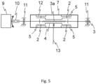
- Fig. 5 shows a schematic representation of another ball screw drive according to the invention with anti-twisting device.
- Fig. 5 The embodiment shown represents the kinematic reversal of the embodiment according to Fig. 1 represents.
- a drive device 9 is connected to a spindle 3 via a coupling 10.
- This has a groove profile 3a on at least part of its circumference and is rotatably mounted via the bearings 11.
- a nut 4 is in engagement with the spindle via balls (not shown) inserted in the groove profile 3a.
- the Spindle 3 penetrates nut 4, as in the embodiment described above, with the two components being oriented coaxially to one another.
- the nut is also mounted in such a way that it can perform a translational movement along the longitudinal direction of spindle 3. Rotation of nut 4 is prevented by anti-twist device 12, which is arranged at both axial ends of the nut.
- the anti-twist device according to the invention consists, as described above, of a securing element 2 and a guide element 5, with securing element 2 engaging in a groove of guide element 5.
- Nut 4 is also connected to an actuating element 13.
- Guide element and groove are as in the ball screw drive of the embodiment according to Figure 1 arranged opposite the securing element in a recess of the housing 7.
- the ball screw drive works as follows. If the drive device 9 exerts a drive movement (rotation) on the spindle 3 via the coupling 10, the spindle is set in a rotary movement.
- the positive connection achieved via the balls between the nut 4 and the spindle 3 means that the nut can move translationally in an axial direction, while the anti-twist device 12 can prevent a rotational movement of the nut 4.
- the actuating element can therefore be moved parallel to a longitudinal axis of the spindle 3.
Landscapes
- Engineering & Computer Science (AREA)
- General Engineering & Computer Science (AREA)
- Mechanical Engineering (AREA)
- Transmission Devices (AREA)
Description
- Die vorliegende Erfindung betrifft einen Kugelgewindetrieb mit einer Verdrehsicherung insbesondere für die Verwendung in einem automatisierten Schaltgetriebe (AMT) zur Umwandlung von rotatorischer in translatorische Bewegung.
- Für die Betätigung von Kupplungen und Gängen in AMT Getrieben können elektrisch angetriebene Aktuatoren eingesetzt werden. Die von einem Elektromotor erzeugte rotatorische Ausgangsbewegung wird dabei in der Regel zunächst in einer Übersetzungsstufe übersetzt und anschließend in eine translatorische Bewegung umgewandelt. Für letzteren Schritt werden in der Praxis häufig Kugelgewindetriebe eingesetzt.
- Diese bestehen in der Regel aus einer Spindel mit einem Laufrillenprofil, in dem Laufrillenprofil befindliche Kugeln und einer Mutter, die mithilfe der Kugeln mit wenig Reibung um die Spindel rotiert. Die Spindel gleitet dabei auf den Kugeln in dem Laufrillenprofil in ihrer Längsrichtung durch den Innendurchmesser der Mutter. Diese verfügt zudem über einen Kugelrückführsystem, das Kugeln an Stellen, an denen sie aufgrund der Bewegung von Mutter und Spindel aus der Kontaktfläche zwischen Mutter und Spindel heraus laufen würden, wieder zu Stellen rückgeführt werden, an denen Kugeln zur Reibungsminderung benötigt werden. Anders ausgedrückt sorgt es also dafür, dass sich immer Kugeln zwischen Mutter und Spindel befinden, um somit möglichst wenig Reibung zwischen Mutter und Spindel gewährleisten zu können. Weiterhin muss sichergestellt werden, dass sich die Spindel durch die Rotation der Mutter nicht mit dreht. Dies wird über eine Verdrehsicherung der Spindel erreicht. Die Verdrehsicherung wird meistens über einen Formschluss zwischen Spindel und Einhausung des Kugelgewindetriebes erreicht. Zur Umsetzung der Verdrehsicherung wird im Stand der Technik in der Regel ein Querbolzen in der Spindel vorgesehen, der über die Spindel in radialer Richtung hinausragt und in für ihn entsprechenden länglichen Nuten in der Einhausung entlang der Betätigungsrichtung geführt wird. Somit kann sich die Spindel zwar in Längsrichtung bewegen, ihr Rotationsfreiheitsgrad ist jedoch durch die Verdrehsicherung blockiert.
- Das Patentdokument
WO2017/005258 A1 offenbart eine Umsetzung einer Verdrehsicherung, in der ein Sicherungselement in Nuten einer Führungshülse mit einem geschlossenen Querschnittsprofil geführt wird. Die Führungshülse ist dabei als dünnes Blech ausgeführt und an einer Seite eingespannt und an der gegenüberliegenden Seite frei. Dadurch kann sich die Führungshülse im Falle einer Rotation des Sicherungselements leicht verdrehen, wodurch sie in Längsrichtung eine Torsion erfährt. - Die beschriebenen Umsetzungen haben allerdings den Nachteil, dass durch Toleranzen, unterschiedliche Reibpaarungen und ungleichmäßige Flächenpressung ein erheblicher Verschleiß zwischen Sicherungselement und Nut der Einhausung entsteht. Bereits geringes Spiel zwischen dem Sicherungselement und der Einhausung führt dazu, dass eine Rotationsbewegung der Mutter ebenfalls zu einer geringen Rotationsbewegung der Spindel führt, bis der Kontakt des Sicherungselementes mit der Einhausung die Rotationsbewegung der Spindel unterbindet.
- Dieser Vorgang führt in der beschriebenen Anordnung des Standes der Technik dazu, dass die Kontaktfläche von Sicherungselement mit der Einhausung, genauer gesagt mit der Seitenfläche der Nut der Einhausung in der das Sicherungselement geführt wird, sehr gering ist, wodurch ein hoher Verschleiß sowohl der Seitenfläche der Nut als auch des Sicherungselements entsteht.
- Es ist somit Aufgabe der vorliegenden Erfindung eine Lösung bereitzustellen, die den Verschleiß einer beschriebenen Anordnung verringert und somit längere Standzeiten der Bauteile und geringere Kosten für Wartungstätigkeiten zu erreichen.
- Diese Aufgabe wird durch die erfindungsgemäßen Gegenstände der unabhängigen Ansprüche gelöst. Vorteilhafte Ausführungsformen sind in den Unteransprüchen enthalten.
- Die Verdrehsicherung des erfindungsgemäßen Kugelgewindetriebes weist ein Sicherungselement auf, das an einem Bewegungselement angeordnet ist, welches dazu konfiguriert ist, sich entlang seiner Längsachse, also in Längsrichtung, zu bewegen und dabei keine Rotationsbewegung auszuführen. Das Sicherungselement ragt dabei an wenigstens einer Stelle aus der Oberfläche des Bewegungselements in radialer Richtung nach außen hinaus.
- Weiterhin weist die Verdrehsicherung des erfindungsgemäßen Kugelgewindetriebes wenigstens ein Führungselement auf, welches wiederum mit einer Nut versehen ist. Als Nut wird dabei eine längliche Vertiefung im Führungselement bezeichnet, die jegliche Querschnittsformen aufweisen kann, und zur Aufnahme des Sicherungselements vorgesehen ist. Das wenigstens eine Führungselement mit der Nut ist dabei in einer Aussparung einer Einhausung des Bewegungselements derart angeordnet, dass die Nut im Wesentlichen parallel zur Längsachse des Bewegungselements liegt und den aus der Oberfläche des Bewegungselements hinausragenden Teil des Sicherungselements bei Längsbewegung des Bewegungselements führt. Erfährt das Bewegungselement ein Moment welches zu einer Rotation des Bewegungselements um die eigene Längsachse führen würde, wird diese Bewegung durch den Eingriff des Sicherungselements in der Nut des Führungselements unterbunden. Zudem weist das wenigstens eine Führungselement keinen offenen Freiheitsgrad entlang der Längsachse der Nut auf, aber wenigstens einen offenen Freiheitsgrad für eine Rotation um eine Achse parallel zur Längsachse der Nut.
- Durch den offenen Rotationsfreiheitsgrad ist es dem Führungselement möglich sich je nach Rotation des Bewegungselements und damit des Sicherungselementes durch die von dem Sicherungselement ausgeübte Kraft auf das Führungselement an diesem auszurichten. Auf diese Weise wird erreicht, dass die Kontaktfläche zwischen Sicherungselement und Führungselement erhöht wird, wodurch der Verschleiß der beteiligten Bauteile verringert werden kann.
- In einer vorteilhaften Ausführungsform und zur Realisierung einer Lösung mit einem möglichst geringen Bauraum ist das Sicherungselement an einem Ende beziehungsweise in einem Endbereich des Bewegungselements angeordnet. Auf diese Weise kann ein in axialer Richtung überstehender Abschnitt des Spindel vermieden werden und eine unnötige Vergrößerung des Bauraums der Vorrichtung insgesamt verhindert werden.
- Weiterhin entspricht in einer vorteilhaften Ausführungsform die Anzahl der Führungselemente der Anzahl der Stellen an denen das wenigstens eine Sicherungselement aus der Oberfläche des Bewegungselements in radialer Richtung hinausragt. Der Vorteil dieser Ausführungsform ist, dass jedes zur Verdrehsicherung beitragende Ende des wenigstens einen Sicherungselements, jeweils ein Führungselement hat und dadurch eine optimale Ausrichtung des jeweiligen Führungselements gewährleistet werden kann. Auf der anderen Seite wird dadurch sichergestellt, dass lediglich die Anzahl der benötigten Führungselemente verbaut werden, was Bearbeitungsaufwand und Kosten spart.
- In einer weiteren vorteilhaften Ausführungsform weist der Querschnitt der Nut des wenigstens einen Führungselements senkrecht zur Längsachse des Führungselements die gleiche Form auf, wie der Querschnitt senkrecht zur Längsachse des Bewegungselements durch den in die Nut des Führungselements hineinragenden Teil des Sicherungselements. Dabei können mehrere Stellen des Sicherungselements in die Nut hineinragen, sowie mehrere Sicherungselemente und Führungselemente vorgesehen sein.
- In einer weiteren vorteilhaften Ausführungsform der Erfindung weist die Verdrehsicherung mindestens 2, bevorzugt gleichmäßig um das Bewegungselement angeordnete Führungselemente auf, um auf diese Weise die von dem wenigstens einen Führungselement aufzunehmende Kraft für jedes Führungselement wenigstens zu halbieren und somit den Verschleiß in jedem einzelnen Führungselement zu verringern.
- Weiterhin vorteilhaft ist eine Ausführungsform des Sicherungselements als Bolzen. Dies bedeutet, dass der Querschnitt des wenigstens einen Sicherungselements senkrecht zur Längsachse des Sicherungselements an einer Stelle, an der das Sicherungselement in die Nut des Führungselements hineinragt, eine kreisförmige Form aufweist.
- In einer weiteren vorteilhaften Ausführungsform ist das mindestens eine Führungselement an seinen Stirnflächen bzw. an seinen Enden in der Einhausung drehbar gelagert. Durch eine derartige Lagerung wird jede Bewegung des Führungselements in der Einhausung unterbunden, außer der Rotation um eine Achse, die durch die Lagerung definiert wird und parallel zur Längsachse des Bewegungselements verläuft. Eine derartige Ausführung hat den Vorteil, dass die Reibung zwischen Führungselement und Einhausung bei der Ausrichtung des Führungselements an dem Sicherungselement minimiert wird und somit der Verschleiß an den beteiligten Bauteilen verringert werden kann.
- In einer weiteren vorteilhaften Ausführungsform der Erfindung ist das wenigstens eine Führungselement in der Aussparung der Einhausung derart angeordnet, dass eine Bewegung des Führungselements in seiner Längsrichtung auf der einen Seite durch den Anschlag an die Einhausung begrenzt ist und eine Bewegung des Führungselements in die entgegengesetzte Richtung durch einen Sicherungsring unterbunden wird, sodass keine Bewegungen in Längsrichtung des Führungselements möglich sind.
- Weiterhin vorteilhaft ist eine Ausführungsform in der das Führungselement einen symmetrischen, bevorzugt kreisförmigen Querschnitt senkrecht zu seiner Längsachse aufweist. Insbesondere durch einen kreisförmigen Querschnitt kann eine geringe Baugröße und einfache Umsetzung der Erfindung garantiert werden.
- In einer weiteren vorteilhaften Ausführungsform haben das Führungselement und die Aussparung der Einhausung, in der das Führungselement untergebracht ist, die gleiche Querschnittsform senkrecht zur Längsachse des Führungselements. Solch eine Ausführung beansprucht somit keinen größeren Bauraum als Verdrehsicherungen nach dem Stand der Technik.
- In einer weiteren vorteilhaften Ausführungsform weist die Nut des wenigstens einen Führungselements einen symmetrischen Querschnitt in Längsrichtung der Nut auf.
- Darüber hinaus ergeben in einer vorteilhaften Ausführungsform das Material des wenigstens einen Führungselements und das Material des wenigstens einen Sicherungselements eine Materialpaarung, die bei Reibung zwischen den Materialien einen geringen Verschleiß und/oder einen geringen Reibwiderstand aufweist. Das Material des wenigstens einen Führungselements ist dabei bevorzugt aus einem harten Material wie beispielsweise einem harten Stahl. Auf diese Weise kann ein erhöhter Verschleiß der Nut und des wenigstens einen Sicherungselements vermieden und geringer Wartungsaufwand sichergestellt werden.
- Weiterhin vorteilhaft ist eine Ausführungsform der Erfindung in der das Ende des Sicherungselements soweit in die Nut hineinragt, dass der Punkt des Sicherungselements, der mit einer der Seitenflächen der Nut bei einer Drehung des Sicherungselements durch eine Drehung des Bewegungselements in Kontakt kommt, weiter entfernt ist von der Oberfläche der Spindel als der Mittelpunkt des Querschnitts des Führungselements senkrecht zu dessen Längsachse.
- Der erfindungsgemäße Kugelgewindetrieb weist eine Spindel mit einem Laufrillenprofil und einem definierten Außendurchmesser und eine Mutter mit definiertem Innendurchmesser, der geringfügig größer ist als der Außendurchmesser der Spindel auf. Des Weiteren enthält er mindestens zwei Kugeln, die zwischen der Mutter und der Spindel in deren Laufrillenprofil angeordnet sind, um eine reibungsarme Bewegung zwischen der Spindel und der Mutter zu ermöglichen. In dieser Anordnung bewegt sich die Spindel in Längsrichtung, wenn die Mutter um die Spindel rotiert. Dabei liegen die Längsachsen der Mutter und der Spindel übereinander und die Mutter rotiert ohne Bewegung in Längsrichtung um die Spindel.
- Um eine rotatorische Bewegung der Spindel zu verhindern, ist der erfindungsgemäße Kugelgewindetrieb mit einer Verdrehsicherung versehen, wobei die Spindel des Kugelgewindetriebs das Bewegungselement der Verdrehsicherung ist. Das Sicherungselement, welches auf der Spindel angeordnet ist, greift also mit seinen überstehenden Enden in die Nut des der Spindel gegenüber angeordneten Führungselementes ein und wird darin geführt. Das Führungselement ist dabei wie oben beschrieben in einer Einhausung der Spindel angeordnet.
- Ein weiterer erfindungsgemäßer Kugelgewindetrieb stellt die kinematische Umkehr des oben erläuterten Kugelgewindetriebs dar. In einer solchen Ausführungsform rotiert die Spindel um die eigene Längsachse, ohne sich in axialer Richtung zu bewegen. Dadurch erfährt die Mutter eine axiale, also translatorische Bewegung, wozu in diesem Fall ihre Rotation unterbunden werden muss. Die Verdrehsicherung ist somit also an der Mutter vorgesehen wodurch diese in diesem Kugelgewindetrieb das Bewegungselement der Verdrehsicherung darstellt. Das wenigstens eine Führungselement mit der Nut in der das Sicherungselement geführt wird, ist folglich gegenüber der Mutter in der Einhausung des Kugelgewindetriebs dieser Ausführungsform angeordnet. Somit kann das Sicherungselement in der Nut des Führungselementes bei translatorischer Bewegung geführt werden und eine Rotation der Mutter wird verhindert.
- Im Folgenden wird die Erfindung anhand von Figuren näher erläutert. Die Figuren zeigen im Einzelnen:
- Fig. 1
- Prinzipskizze des Aufbaus einer Ausführungsform des erfindungsgemäßen Kugelgewindetriebes
- Fig. 2
- Querschnittsansicht durch das Sicherungselement der Spindel, die Spindel selbst und zweier Führungselemente der Ausführungsform aus
Figur 1 - Fig. 3
- Detailansicht der Querschnittsansicht aus
Figur 2 zur Darstellung des Funktionsprinzips des erfindungsgemäßen Kugelgewindetriebs - Fig. 4
- weitere Detailansicht der
Figur 2 zur Darstellung des Funktionsprinzips zur Ausrichtung des Führungselements. - Fig. 5
- schematische Darstellung zur Erläuterung einer weiteren Ausführungsform eines erfindungsgemäßen Kugelgewindetriebs mit Verdrehsicherung
-
Fig. 1 zeigt eine Prinzipskizze des Aufbaus einer Ausführungsform des erfindungsgemäßen Kugelgewindetriebes mit einer erfindungsgemäßen Verdrehsicherung. Die zentralen Bauteile des Kugelgewindetriebes 1 stellen die Spindel 3 und die um die Längsachse der Spindel rotierende Mutter 4 dar. Zwischen Mutter und Spindel sind dabei Kugeln angeordnet, um eine möglichst reibungsarme Rotation der Mutter 4 zu gewährleisten. Die Kugeln werden dabei in einem in derFigur 1 nicht dargestellten Laufrillenprofil in der Spindel 3 geführt. Die Mutter 4 ist an ihrem Außendurchmesser durch die Kugellager 6 rotatorisch gelagert, sodass eine Drehbewegung der Mutter 4 um die Spindel 3 möglich ist, eine Bewegung der Mutter 4 in Längsrichtung der Spindel 3 allerdings verhindert wird. - Wird die Mutter 4 durch z.B. einem Elektromotor (nicht dargestellt) in Rotation versetzt, wird die rotatorische Bewegung der Mutter 4 durch die in dem Laufrillenprofil der Spindel 3 geführten Kugeln in eine translatorische Bewegung (in Zeichenebene nach rechts bzw. links) der Spindel 3 umgesetzt. Da die Kugeln durch die Rotationsbewegung der Mutter 4 und der dadurch hervorgerufenen translatorischen Bewegung der Spindel 3 entlang des Laufrillenprofils aus dem Bereich zwischen Mutter 4 und Spindel 3 herauswandern würden, müssen die Kugeln vom einen Ende der Mutter 4 an das andere Ende zurückgeführt werden. Dies geschieht über ein nicht dargestelltes und im Stand der Technik bekanntes Rückführsystem innerhalb der Mutter 4.
- Um eine Rotation der Spindel 3 durch die dynamische Drehung der Mutter 4 zu verhindern, ist es notwendig die Drehbewegung der Spindel 3 durch eine Verdrehsicherung zu unterbinden. Die Verdrehsicherung besteht in der in
Figur 1 dargestellten Ausführungsform aus drei Bauteilen. Zum einen ist am Ende der Spindel 3, welche hier als Bewegungselement zu verstehen ist, ein Sicherungselement 2 vorgesehen, welches senkrecht zur Längsachse der Spindel 3 angeordnet ist. Das Sicherungselement 2 weist weiterhin einen kreisförmigen Querschnitt in einer Schnittrichtung senkrecht zur Längsachse des Sicherungselements 2 auf. Es ist somit als zylindrische Bolzen zu beschreiben der senkrecht auf die Längsachse der Spindel 3 steht. Zudem ragt der Bolzen mit beiden Enden deutlich aus der Oberfläche der Spindel 3 in radialer Richtung nach außen hinaus. Die Stirnflächen des Bolzens sind in dieser Ausführungsform als ebene Flächen ausgeführt. - Bei den anderen beiden Bauteilen der Verdrehsicherung handelt es sich um Führungselemente 5, die direkt gegenüberliegend, in Zeichnungsebene oberhalb und unterhalb der Spindel 3, parallel zur Längsachse der Spindel 3 angeordnet sind. Wie die Spindel 3 und das Sicherungselement 2 weisen auch die Führungselemente 5 einen kreisförmigen Querschnitt auf und können somit als Zylinder mit ebenen Stirnflächen beschrieben werden.
- An der jeweils der Spindel 3 zugewandten Seite weisen die beiden Führungselement 5 eine Nut auf (in
Fig. 1 nicht dargestellt), welche jeweils die Enden des Sicherungselements 2 aufnehmen. Die Nuten sind dabei derart in den Führungselementen 5 angeordnet, dass bei einer translatorische Bewegung der Spindel 3 nach links (in Zeichenebene), die Spindel 3 über das Sicherungselement 2 in den Nuten über die gesamte Betätigungslänge Lb geführt und eine Rotation der Spindel 3 vermieden werden kann. Zudem entsprechen die Querschnittsformen der Nuten den jeweils zu führenden Enden des Sicherungselements 3, sodass die Querschnitte der Nuten möglichst vollständig von den Enden des Sicherungselements 2 ausgefüllt sind, ohne dabei die translatorische Bewegung des Sicherungselements 2 entlang der Nuten zu behindern. - Die Führungselemente 5 sind ihrerseits jeweils in einer Aussparung einer Einhausung 8 des Kugelgewindetriebs 1 angeordnet. Dabei weisen die Aussparungen und die Führungselemente 5 die gleiche Querschnittsform senkrecht zur Längsachse der Führungselemente 5 auf. Es ist zu beachten, dass der Radius des beschriebenen Querschnitts der Führungselemente 5 geringfügig kleiner ist als der Radius der Querschnitte der jeweiligen Aussparungen. Eine Bewegung in Längsrichtung wird auf der einen Seite durch den Anschlag der Führungselemente 5 an der Einhausung 8 (in Zeichenebene rechte Seite) und auf der anderen Seite durch einen Sicherungsring 9 (in Zeichenebene linke Seite) begrenzt. Somit können sich die Führungselemente 5 in ihren Aussparungen um ihre Längsachsen drehen, während eine translatorische Bewegung der Führungselemente in Längsrichtung nicht möglich ist.
-
Fig. 2 zeigt eine Querschnittsansicht der Ausführungsform des Kugelgewindetriebs ausFig. 1 . Der Schnitt verläuft dabei auf Höhe des Sicherungselements, sodass die Spindel 3, dass Sicherungselement 2 und die beiden Führungselemente 5 gezeigt werden. Zu erkennen sind dabei die kreisförmigen Querschnitte der Spindel 3 und der beiden Führungselemente 5. Das Sicherungselement 2 greift dabei mit den jeweiligen Enden in die Nut des Führungselements 5 ein. Die Bewegung der Spindel und damit des Sicherungselements 2 verläuft in dieser Ansicht in die Zeichenebene hinein bzw. aus ihr heraus. -
Fig. 3 zeigt eine Detailansicht der Querschnittsansicht ausFigur 2 , wobei lediglich das untere Führungselement 5 und der untere Teil der Spindel 3 und des Sicherungselements 2 betrachtet werden. Es wird darauf hingewiesen, dass um das Prinzip der Erfindung besser erklären zu können die Nut des Führungselements 5 deutlich größer dargestellt wurde als das Ende des Sicherungselement 2, sodass zwischen der Nut und dem Sicherungselement 2 ein deutliches Spiel zu sehen ist. - Die Spindel 3 und damit auch das Sicherungselement 2 weisen einen leichten Verdrehwinkel in Relation zum Führungselement 5 auf. Dieser resultiert aus einer leichten Rotation der Spindel 3, die durch das Drehmoment Ms hervorgerufen wurde, welches wiederum durch die Rotation der Mutter 4 auf die Spindel 3 wirkt. Da die Nut einen größeren Querschnitt aufweist als das Sicherungselement 2 im Bereich der Nut, kann sich das Ende des Sicherungselements 2 zunächst in der Nut bewegen. Ab einem gewissen Verdrehwinkel kommt das Sicherungselement mit einer Seitenfläche der Nut in Kontakt (dargestellter Zustand). Der Kontaktpunkt des Endes des Sicherungselements 2 liegt dabei in Zeichnungsebene unterhalb von dem Mittelpunkt des im Wesentlichen kreisförmigen Querschnitts des Führungselements 5. Dies ist in
Figur 3 durch den Abstand La zwischen dem Mittelpunkt des Querschnitts des Führungselementes und dem Berührungspunkt zwischen Nut und Sicherungselement 2 gekennzeichnet. - Nach dem Kontakt des Sicherungselements mit dem Führungselement wird nun das Moment Ms auf das Führungselement 5 übertragen. Da sich dieses in der Aussparung der Einhausung (nicht dargestellt in
Fig. 3 ) in Zeichenebene leicht bewegen und insbesondere drehen kann führt das Moment Ms des Sicherungselementes 2 zu einem Moment Mf des Führungselementes 5, was insbesondere eine Drehung des Führungselements 5 in der Aussparung zur Folge hat. -
Fig 4 zeigt die Ausrichtung des Führungselements 5 in Folge des Moments Mf. Die linke Darstellung zeigt die inFigur 3 bereits beschriebene Situation. Das Sicherungselement 2 ist mit einer Seitenfläche der Nut in Kontakt, sodass das Moment Ms auf das Führungselement 5 übertragen wird und das Moment Mf hervorruft. Dieses führt anschließend zu einer Drehung des Führungselements 5 um eine Achse parallel zu dessen Längsachse. Die Folge ist, dass sich das Führungselement 5 derart ausrichtet, dass das Sicherungselement 2 mit seiner gesamten Seitenfläche, welche sich innerhalb der Nut befindet, mit der Seitenfläche der Nut in Kontakt steht. - In dieser Stellung kann das Moment Ms nicht weiter an das Führungselement 5 übertragen werden, wodurch das Moment Mf nicht länger auf das Führungselement 5 wirkt. Die Rotation des Führungselements 5 stoppt demnach und das Führungselement 5 hat seine Endlage erreicht.
- In dieser Endlage ist im Vergleich zur in der linken Darstellung gezeigten Position ein Linienkontakt statt eines punktförmigen Kontakts zwischen Sicherungselement 2 und Führungselement 5 entstanden. Die über das Moment Ms des Sicherungselements 2 einwirkende Kraft verteilt sich somit auf einen größeren Bereich als in der linken Darstellung der
Figur 4 . - Bei herkömmlichen Lösungen nach dem Stand der Technik wird, wie eingangs beschrieben, ein Sicherungselement in einer Nut in der Einhausung des Kugelgewindetriebs geführt. Die Lösung nach dem Stand der Technik ist somit durch die linke Darstellung der
Figur 4 repräsentiert. Durch das Ausrichten des Führungselements 5 (vgl rechte Darstellung) und die damit einhergehende Krafteinleitung in das Führungselement 5 beziehungsweise die Einhausung (nicht dargestellt inFig. 4 ) über die größere Auflagefläche des Sicherungselements 2 an der Seitenfläche der Nut, kann ein geringerer Verschleiß zwischen Sicherungselement 2 und Führungselement 5 erzielt werden und eine Verdrehung der Spindel trotzdem sicher gestellt werden. -
Fig. 5 zeigt eine schematische Darstellung eines weiteren erfindungsgemäßen Kugelgewindetriebs mit Verdrehsicherung. Die inFig. 5 gezeigte Ausführungsform stellt die kinematische Umkehr der Ausführungsform gemäßFig. 1 dar. - Eine Antriebsvorrichtung 9 ist über eine Kupplung 10 mit einer Spindel 3 verbunden. Diese weist zumindest auf einem Teil ihres Umfangs ein Laufrillenprofil 3a auf und ist über die Lager 11 rotatorisch gelagert. Eine Mutter 4 befindet sich über in dem Laufrillenprofil 3a eingesetzte Kugeln (nicht dargestellt) mit der Spindel im Eingriff. Die Spindel 3 durchdringt dabei die Mutter 4, wie auch in der oben ausgeführten Ausführungsform, wobei die beiden Bauteile koaxial zueinander orientiert sind. Die Mutter ist zudem derart gelagert, dass sie eine translatorische Bewegung entlang der Längsrichtung der Spindel 3 durchführen kann. Durch die Verdrehsicherung 12, die an beiden axialen Enden der Mutter angeordnet ist, wird eine Rotation der Mutter 4 unterbunden. Die erfindungsgemäße Verdrehsicherung besteht wie oben beschrieben aus einem Sicherungselement 2 und einem Führungselement 5, wobei das Sicherungselement 2 in eine Nut des Führungselements 5 eingreift. Die Mutter 4 ist weiterhin mit einem Betätigungselement 13 verbunden. Führungselement und Nut sind wie im Kugelgewindetrieb der Ausführungsform gemäß
Figur 1 gegenüberliegend vom Sicherungselement in einer Aussparung der Einhausung 7 angeordnet. - Die Funktionsweise des Kugelgewindetriebes lautet wie folgt. Wird durch die Antriebsvorrichtung 9 eine Antriebsbewegung (Rotation) über die Kupplung 10 auf die Spindel 3 ausgeübt, so wird die Spindel in eine Drehbewegung versetzt. Der über die Kugeln zwischen Mutter 4 und Spindel 3 erreichte Formschluss führt dazu, dass die Mutter sich in einer axialen Richtung translatorisch bewegen kann, während durch die Verdrehsicherung 12 eine Rotationsbewegung der Mutter 4 verhindert werden kann. Somit kann das Betätigungselement parallel zu einer Längsachse der Spindel 3 bewegt werden.
-
- 1
- Kugelgewindetrieb
- 2
- Sicherungselement
- 3
- Spindel
- 3a
- Laufrillenprofil
- 4
- Mutter
- 5
- Führungselement
- 6
- Kugellager
- 7
- Einhausung
- 8
- Sicherungsring
- 9
- Antriebsvorrichtung
- 10
- Kupplung
- 11
- Lager
- 12
- Verdrehsicherung
- 13
- Betätigungselement
- Lb
- Betätigungslänge
- Ms
- auf die Spindel wirkendes Drehmoment
- Mf
- auf Führungselement wirkendes Drehmoment
Claims (12)
- Kugelgewindetrieb mit Verdrehsicherung aufweisend:eine Spindel (3) mit Laufrillenprofil und definiertem Außendurchmesser,eine Mutter (4) mit definiertem Innendurchmesser, der geringfügig größer ist als der Außendurchmesser der Spindel (3),wenigstens zwei Kugeln, die zwischen der Mutter (4) und der Spindel (3) in deren Laufrillenprofil angeordnet sind und dazu konfiguriert sind, eine reibungsarme Bewegung der Spindel (3) entlang der Längsrichtung der Mutter (4) zu ermöglichen,wobei die Mittelachsen des Innendurchmessers der Mutter (4) und des Außendurchmessers der Spindel (3) übereinander liegen unddie Mutter (4) dazu konfiguriert ist, ohne Bewegung in Längsrichtung um die Spindel (3) zu rotieren, und die Spindel (3) dazu konfiguriert ist, sich ohne Rotation in Längsrichtung zu bewegen, oderdie Mutter (4) dazu konfiguriert ist, sich ohne Rotation um die Spindel (3) in Längsrichtung der Spindel (3) zu bewegen, und die Spindel (3) dazu konfiguriert ist, ohne Bewegung in ihrer Längsrichtung in der Mutter (4) zu rotieren, undeine Verdrehsicherung aufweisend:wenigstens ein Sicherungselement (2), das an einem Bewegungselement, welches dazu konfiguriert ist, sich ohne Rotation in Längsrichtung zu bewegen, vorgesehen ist und an wenigstens einer Stelle aus der Oberfläche des Bewegungselements in radialer Richtung nach außen hinausragt, wobeidie Spindel (3) dazu konfiguriert ist, als das Bewegungselement zu fungieren, wenn die Spindel (3) dazu konfiguriert ist, sich ohne Rotation in Längsrichtung zu bewegen, oderdie Mutter (4) dazu konfiguriert ist, als das Bewegungselement zu fungieren, wenn die Mutter (4) dazu konfiguriert ist, sich ohne Rotation um die Spindel (3) in Längsrichtung der Spindel (3) zu bewegen, undwenigstens ein Führungselement (5), das eine Nut aufweist und das dazu konfiguriert ist, in einer Aussparung einer Einhausung (7) des Bewegungselements derart angeordnet zu sein, dass seine Nut im Wesentlichen parallel zur Längsachse des Bewegungseelements angeordnet ist, und den überstehenden Teil des Sicherungselementes (2) bei Längsbewegung des Bewegungselements in seiner Nut zu führen,dadurch gekennzeichnet, dass das wenigstens eine Führungselement (5) so ausgebildet ist, dass es keinen Freiheitsgrad entlang der Längsachse der Nut, aber wenigstens den Rotationsfreiheitsgrad um eine Achse parallel zur Längsachse der Nut aufweist.
- Kugelgewindetrieb gemäß einem der vorhergehenden Ansprüche, wobei die Anzahl der Führungselemente (5) der Anzahl der Stellen entspricht, an denen das wenigstens eine Sicherungselement (2) aus der Oberfläche des Bewegungselements in radialer Richtung hinausragt.
- Kugelgewindetrieb gemäß einem der vorhergehenden Ansprüche, wobei der Querschnitt der Nut des wenigstens einen Führungselements (5) senkrecht zu ihrer Längsrichtung die gleiche Form aufweist, wie der Querschnitt senkrecht zur Längsrichtung des Bewegungselements des wenigstens einen in die Nut des Führungselementes (5) hineinragenden Endes des wenigstens einen Sicherungselements (2).
- Kugelgewindetrieb gemäß einem der vorhergehenden Ansprüche, wobei im Falle mehrerer Führungselemente (5) diese über den Umfang des Bewegungselements gleichmäßig verteilt sind.
- Kugelgewindetrieb gemäß einem der vorhergehenden Ansprüche, wobei das wenigstens eine Ende des wenigstens einen Sicherungselementes (2) das in die Nut des wenigstens einen Führungselementes (5) hineinragt einen senkrecht zur Längsrichtung des wenigstens einen Sicherungselements (2) verlaufenden kreisförmigen Querschnitt aufweist.
- Kugelgewindetrieb gemäß einem der vorhergehenden Ansprüche, wobei das wenigstens eine Führungselement (5) in der Einhausung an seinen Enden in Längsrichtung gelagert ist, wobei die Lagerung dazu konfiguriert ist eine reibungsarme Rotation des Führungselements (5) um eine Achse parallel zur Längsachse des Bewegungselements zu ermöglichen und jede translatorische Bewegung des wenigstens einen Führungselements (5) zu verhindern.
- Kugelgewindetrieb gemäß einem der vorhergehenden Ansprüche, wobei das wenigstens eine Führungselement (5) einen symmetrischen und bevorzugt einen kreisförmigen Querschnitt senkrecht zu seiner Längsrichtung aufweist.
- Kugelgewindetrieb gemäß einem der vorhergehenden Ansprüche, wobei das wenigstens eine Führungselement (5) und die Aussparung der Einhausung im Wesentlichen die gleiche Querschnittsform senkrecht zu ihrer Längsrichtung aufweisen.
- Kugelgewindetrieb gemäß einem der vorhergehenden Ansprüche, wobei ein Material des wenigstens einen Führungselements (5) und ein Material des wenigstens einen Sicherungselements (2) eine Materialpaarung ergeben, die bei Reibung zwischen den Materialien einen geringen Verschleiß und/oder einen geringen Reibwiderstand aufweist, wobei das Material des wenigstens einen Führungselements (5) ein bevorzugt hartes Material wie Stahl ist.
- Kugelgewindetrieb gemäß einem der vorhergehenden Ansprüche, wobei der das Bewegungselement eine Einhausung aufweist, die mindestens das Bewegungselement umgibt und als Gehäuse dient, wobei das wenigstens eine Führungselement (5) in der Einhausung derart angeordnet ist, dass es auf der einen Seite an der Einhausung anstößt und auf anderen Seite mit einem Sicherungsring fixiert wird, sodass keine Bewegung in Längsrichtung des Führungselementes (5) möglich ist.
- Kugelgewindetrieb gemäß einem der vorhergehenden Ansprüche, wobei die Nut des wenigstens einen Führungselements (5) einen symmetrischen Querschnitt in Längsrichtung der Nut aufweist.
- Kugelgewindetrieb gemäß einem der vorhergehenden Ansprüche, wobei das Sicherungselement (2) an der wenigstens einen Stelle so weit in die Nut des wenigstens einen Führungselements (5) hineinragt, dass der Punkt des wenigstens einen Sicherungselementes (2), der mit einem der Seitenflächen der Nut bei einer Drehung des Sicherungselementes (2) mit der Nut in Kontakt kommt weiter entfernt ist von der Oberfläche des Bewegungselements als der Mittelpunkt des Querschnitts des Führungselements (5).
Applications Claiming Priority (2)
| Application Number | Priority Date | Filing Date | Title |
|---|---|---|---|
| DE102019104125.2A DE102019104125A1 (de) | 2019-02-19 | 2019-02-19 | Kugelgewindetrieb mit Verdrehsicherung |
| PCT/EP2020/052003 WO2020169309A1 (de) | 2019-02-19 | 2020-01-28 | Kugelgewindetrieb mit verdrehsicherung |
Publications (2)
| Publication Number | Publication Date |
|---|---|
| EP3927997A1 EP3927997A1 (de) | 2021-12-29 |
| EP3927997B1 true EP3927997B1 (de) | 2024-10-16 |
Family
ID=69411417
Family Applications (1)
| Application Number | Title | Priority Date | Filing Date |
|---|---|---|---|
| EP20702981.0A Active EP3927997B1 (de) | 2019-02-19 | 2020-01-28 | Kugelgewindetrieb mit verdrehsicherung |
Country Status (6)
| Country | Link |
|---|---|
| US (1) | US12241528B2 (de) |
| EP (1) | EP3927997B1 (de) |
| JP (1) | JP2022521218A (de) |
| CN (1) | CN113490803B (de) |
| DE (1) | DE102019104125A1 (de) |
| WO (1) | WO2020169309A1 (de) |
Families Citing this family (1)
| Publication number | Priority date | Publication date | Assignee | Title |
|---|---|---|---|---|
| DE102022204005A1 (de) | 2022-04-26 | 2023-10-26 | Zf Friedrichshafen Ag | Aktuatorsystem |
Family Cites Families (10)
| Publication number | Priority date | Publication date | Assignee | Title |
|---|---|---|---|---|
| DE10311896A1 (de) | 2003-03-18 | 2004-09-30 | Knorr-Bremse Systeme für Nutzfahrzeuge GmbH | Scheibenbremse, insbesondere für Nutzfahrzeuge |
| CN2900933Y (zh) * | 2005-12-23 | 2007-05-16 | 绍兴威煌电机厂 | 滚珠螺杆推拉器 |
| DE202006014177U1 (de) * | 2006-09-12 | 2006-11-23 | Klann-Spezial-Werkzeugbau-Gmbh | Vorrichtung zum Ausziehen eines in einer Bohrung eines Bauteils sitzenden Bauelements |
| DE102008051544B4 (de) * | 2008-10-14 | 2012-12-27 | Continental Automotive Gmbh | Spindeltrieb mit Verdrehsicherung |
| JP5293887B2 (ja) | 2010-04-26 | 2013-09-18 | 日本精工株式会社 | 直動アクチュエータ |
| DE102011119724B4 (de) * | 2011-11-30 | 2020-07-16 | Thyssenkrupp Presta Aktiengesellschaft | Verdrehsicherung am Lenkgetriebe |
| JP6091148B2 (ja) * | 2012-10-12 | 2017-03-08 | Ntn株式会社 | 電動リニアアクチュエータ |
| DE102015209600B4 (de) * | 2015-05-26 | 2021-11-11 | Schaeffler Technologies AG & Co. KG | Kugelgewindetrieb |
| DE102015212643A1 (de) * | 2015-07-07 | 2017-01-12 | Schaeffler Technologies AG & Co. KG | Gewindetrieb |
| DE102018212694A1 (de) * | 2018-07-30 | 2020-01-30 | Knorr-Bremse Systeme für Nutzfahrzeuge GmbH | Schaltmechanismus für ein Getriebe |
-
2019
- 2019-02-19 DE DE102019104125.2A patent/DE102019104125A1/de active Pending
-
2020
- 2020-01-28 EP EP20702981.0A patent/EP3927997B1/de active Active
- 2020-01-28 WO PCT/EP2020/052003 patent/WO2020169309A1/de not_active Ceased
- 2020-01-28 JP JP2021548595A patent/JP2022521218A/ja active Pending
- 2020-01-28 CN CN202080015350.9A patent/CN113490803B/zh active Active
- 2020-01-28 US US17/431,955 patent/US12241528B2/en active Active
Also Published As
| Publication number | Publication date |
|---|---|
| US20220154808A1 (en) | 2022-05-19 |
| CN113490803B (zh) | 2023-11-24 |
| EP3927997A1 (de) | 2021-12-29 |
| CN113490803A (zh) | 2021-10-08 |
| JP2022521218A (ja) | 2022-04-06 |
| DE102019104125A1 (de) | 2020-08-20 |
| US12241528B2 (en) | 2025-03-04 |
| WO2020169309A1 (de) | 2020-08-27 |
Similar Documents
| Publication | Publication Date | Title |
|---|---|---|
| DE102011050814B3 (de) | Welle mit einem Lager | |
| EP3417183B1 (de) | Kugelgelenk | |
| DE3508969A1 (de) | Stellmotor | |
| EP3927997B1 (de) | Kugelgewindetrieb mit verdrehsicherung | |
| DE2809221C2 (de) | Lenkgetriebe für Kraftfahrzeuge mit änderbarem Übersetztungsverhältnis | |
| EP0622574A2 (de) | Betätigungsvorrichtung für ein drehbares Verschlussstück eines Ventils | |
| EP0049903A2 (de) | Schraubtrieb mit Doppelmutter | |
| DE102012215418B4 (de) | Verriegelungsmechanismus | |
| EP1898122A2 (de) | Stellvorrichtung zur linearen Verstellung eines Stellgliedes | |
| DE102007038264A1 (de) | Aktiver Stabilisator zur Wankstabilisierung | |
| CH669636A5 (de) | ||
| DE102015205889B4 (de) | Planetenwälzgewindetrieb (PWG) und Aktor mit einem Planetenwälzgewindetrieb | |
| DE102018206551A1 (de) | Spindelantrieb für einen Aktuator einer steer-by-wire-Lenkung | |
| DE2107378A1 (de) | Getriebe | |
| EP2072861B1 (de) | Verdrehsicherung mit Toleranzausgleich | |
| EP1741664B1 (de) | Stelleinrichtung zum Positionieren einer Last | |
| EP3835621B1 (de) | Stellantrieb | |
| EP3228749B1 (de) | Vorrichtung zum verriegeln zweier bauelemente | |
| DE19729160C2 (de) | Sperrvorrichtung | |
| DE102017212070A1 (de) | Zahnstangengetriebe für ein Kraftfahrzeug | |
| DE102023126980A1 (de) | Sicherheitselement sowie Kupplung umfassend mehrere dieser Sicherheitselemente | |
| DE1450804C (de) | Ventilbetatigungsvornchtung mit Gewindespindel | |
| DE1775825A1 (de) | Langsam laufender Antrieb | |
| DE2334336B2 (de) | SteUgetriebe insbesondere für Klappenventile | |
| DE102019121688A1 (de) | Wellenlagerung, Getriebe sowie Verwendung eines Sicherungsrings |
Legal Events
| Date | Code | Title | Description |
|---|---|---|---|
| STAA | Information on the status of an ep patent application or granted ep patent |
Free format text: STATUS: UNKNOWN |
|
| STAA | Information on the status of an ep patent application or granted ep patent |
Free format text: STATUS: THE INTERNATIONAL PUBLICATION HAS BEEN MADE |
|
| PUAI | Public reference made under article 153(3) epc to a published international application that has entered the european phase |
Free format text: ORIGINAL CODE: 0009012 |
|
| STAA | Information on the status of an ep patent application or granted ep patent |
Free format text: STATUS: REQUEST FOR EXAMINATION WAS MADE |
|
| 17P | Request for examination filed |
Effective date: 20210920 |
|
| AK | Designated contracting states |
Kind code of ref document: A1 Designated state(s): AL AT BE BG CH CY CZ DE DK EE ES FI FR GB GR HR HU IE IS IT LI LT LU LV MC MK MT NL NO PL PT RO RS SE SI SK SM TR |
|
| DAV | Request for validation of the european patent (deleted) | ||
| DAX | Request for extension of the european patent (deleted) | ||
| STAA | Information on the status of an ep patent application or granted ep patent |
Free format text: STATUS: EXAMINATION IS IN PROGRESS |
|
| 17Q | First examination report despatched |
Effective date: 20230606 |
|
| RAP3 | Party data changed (applicant data changed or rights of an application transferred) |
Owner name: KNORR-BREMSE SYSTEME FUER NUTZFAHRZEUGE GMBH |
|
| GRAP | Despatch of communication of intention to grant a patent |
Free format text: ORIGINAL CODE: EPIDOSNIGR1 |
|
| STAA | Information on the status of an ep patent application or granted ep patent |
Free format text: STATUS: GRANT OF PATENT IS INTENDED |
|
| INTG | Intention to grant announced |
Effective date: 20240619 |
|
| GRAS | Grant fee paid |
Free format text: ORIGINAL CODE: EPIDOSNIGR3 |
|
| GRAA | (expected) grant |
Free format text: ORIGINAL CODE: 0009210 |
|
| STAA | Information on the status of an ep patent application or granted ep patent |
Free format text: STATUS: THE PATENT HAS BEEN GRANTED |
|
| AK | Designated contracting states |
Kind code of ref document: B1 Designated state(s): AL AT BE BG CH CY CZ DE DK EE ES FI FR GB GR HR HU IE IS IT LI LT LU LV MC MK MT NL NO PL PT RO RS SE SI SK SM TR |
|
| REG | Reference to a national code |
Ref country code: GB Ref legal event code: FG4D Free format text: NOT ENGLISH |
|
| P01 | Opt-out of the competence of the unified patent court (upc) registered |
Free format text: CASE NUMBER: APP_52329/2024 Effective date: 20240918 |
|
| REG | Reference to a national code |
Ref country code: CH Ref legal event code: EP Ref country code: DE Ref legal event code: R096 Ref document number: 502020009498 Country of ref document: DE |
|
| REG | Reference to a national code |
Ref country code: IE Ref legal event code: FG4D Free format text: LANGUAGE OF EP DOCUMENT: GERMAN |
|
| REG | Reference to a national code |
Ref country code: SE Ref legal event code: TRGR |
|
| REG | Reference to a national code |
Ref country code: LT Ref legal event code: MG9D |
|
| REG | Reference to a national code |
Ref country code: NL Ref legal event code: MP Effective date: 20241016 |
|
| PG25 | Lapsed in a contracting state [announced via postgrant information from national office to epo] |
Ref country code: NL Free format text: LAPSE BECAUSE OF FAILURE TO SUBMIT A TRANSLATION OF THE DESCRIPTION OR TO PAY THE FEE WITHIN THE PRESCRIBED TIME-LIMIT Effective date: 20241016 |
|
| PG25 | Lapsed in a contracting state [announced via postgrant information from national office to epo] |
Ref country code: NL Free format text: LAPSE BECAUSE OF FAILURE TO SUBMIT A TRANSLATION OF THE DESCRIPTION OR TO PAY THE FEE WITHIN THE PRESCRIBED TIME-LIMIT Effective date: 20241016 |
|
| PG25 | Lapsed in a contracting state [announced via postgrant information from national office to epo] |
Ref country code: HR Free format text: LAPSE BECAUSE OF FAILURE TO SUBMIT A TRANSLATION OF THE DESCRIPTION OR TO PAY THE FEE WITHIN THE PRESCRIBED TIME-LIMIT Effective date: 20241016 Ref country code: IS Free format text: LAPSE BECAUSE OF FAILURE TO SUBMIT A TRANSLATION OF THE DESCRIPTION OR TO PAY THE FEE WITHIN THE PRESCRIBED TIME-LIMIT Effective date: 20250216 Ref country code: PT Free format text: LAPSE BECAUSE OF FAILURE TO SUBMIT A TRANSLATION OF THE DESCRIPTION OR TO PAY THE FEE WITHIN THE PRESCRIBED TIME-LIMIT Effective date: 20250217 |
|
| PGFP | Annual fee paid to national office [announced via postgrant information from national office to epo] |
Ref country code: DE Payment date: 20250129 Year of fee payment: 6 |
|
| PG25 | Lapsed in a contracting state [announced via postgrant information from national office to epo] |
Ref country code: FI Free format text: LAPSE BECAUSE OF FAILURE TO SUBMIT A TRANSLATION OF THE DESCRIPTION OR TO PAY THE FEE WITHIN THE PRESCRIBED TIME-LIMIT Effective date: 20241016 |
|
| PG25 | Lapsed in a contracting state [announced via postgrant information from national office to epo] |
Ref country code: BG Free format text: LAPSE BECAUSE OF FAILURE TO SUBMIT A TRANSLATION OF THE DESCRIPTION OR TO PAY THE FEE WITHIN THE PRESCRIBED TIME-LIMIT Effective date: 20241016 |
|
| PG25 | Lapsed in a contracting state [announced via postgrant information from national office to epo] |
Ref country code: ES Free format text: LAPSE BECAUSE OF FAILURE TO SUBMIT A TRANSLATION OF THE DESCRIPTION OR TO PAY THE FEE WITHIN THE PRESCRIBED TIME-LIMIT Effective date: 20241016 |
|
| PGFP | Annual fee paid to national office [announced via postgrant information from national office to epo] |
Ref country code: SE Payment date: 20250127 Year of fee payment: 6 |
|
| PG25 | Lapsed in a contracting state [announced via postgrant information from national office to epo] |
Ref country code: NO Free format text: LAPSE BECAUSE OF FAILURE TO SUBMIT A TRANSLATION OF THE DESCRIPTION OR TO PAY THE FEE WITHIN THE PRESCRIBED TIME-LIMIT Effective date: 20250116 |
|
| PG25 | Lapsed in a contracting state [announced via postgrant information from national office to epo] |
Ref country code: LV Free format text: LAPSE BECAUSE OF FAILURE TO SUBMIT A TRANSLATION OF THE DESCRIPTION OR TO PAY THE FEE WITHIN THE PRESCRIBED TIME-LIMIT Effective date: 20241016 Ref country code: GR Free format text: LAPSE BECAUSE OF FAILURE TO SUBMIT A TRANSLATION OF THE DESCRIPTION OR TO PAY THE FEE WITHIN THE PRESCRIBED TIME-LIMIT Effective date: 20250117 |
|
| PG25 | Lapsed in a contracting state [announced via postgrant information from national office to epo] |
Ref country code: PL Free format text: LAPSE BECAUSE OF FAILURE TO SUBMIT A TRANSLATION OF THE DESCRIPTION OR TO PAY THE FEE WITHIN THE PRESCRIBED TIME-LIMIT Effective date: 20241016 |
|
| PG25 | Lapsed in a contracting state [announced via postgrant information from national office to epo] |
Ref country code: RS Free format text: LAPSE BECAUSE OF FAILURE TO SUBMIT A TRANSLATION OF THE DESCRIPTION OR TO PAY THE FEE WITHIN THE PRESCRIBED TIME-LIMIT Effective date: 20250116 |
|
| PG25 | Lapsed in a contracting state [announced via postgrant information from national office to epo] |
Ref country code: SM Free format text: LAPSE BECAUSE OF FAILURE TO SUBMIT A TRANSLATION OF THE DESCRIPTION OR TO PAY THE FEE WITHIN THE PRESCRIBED TIME-LIMIT Effective date: 20241016 |
|
| PG25 | Lapsed in a contracting state [announced via postgrant information from national office to epo] |
Ref country code: DK Free format text: LAPSE BECAUSE OF FAILURE TO SUBMIT A TRANSLATION OF THE DESCRIPTION OR TO PAY THE FEE WITHIN THE PRESCRIBED TIME-LIMIT Effective date: 20241016 |
|
| REG | Reference to a national code |
Ref country code: DE Ref legal event code: R097 Ref document number: 502020009498 Country of ref document: DE |
|
| PG25 | Lapsed in a contracting state [announced via postgrant information from national office to epo] |
Ref country code: EE Free format text: LAPSE BECAUSE OF FAILURE TO SUBMIT A TRANSLATION OF THE DESCRIPTION OR TO PAY THE FEE WITHIN THE PRESCRIBED TIME-LIMIT Effective date: 20241016 |
|
| PG25 | Lapsed in a contracting state [announced via postgrant information from national office to epo] |
Ref country code: RO Free format text: LAPSE BECAUSE OF FAILURE TO SUBMIT A TRANSLATION OF THE DESCRIPTION OR TO PAY THE FEE WITHIN THE PRESCRIBED TIME-LIMIT Effective date: 20241016 |
|
| PG25 | Lapsed in a contracting state [announced via postgrant information from national office to epo] |
Ref country code: SK Free format text: LAPSE BECAUSE OF FAILURE TO SUBMIT A TRANSLATION OF THE DESCRIPTION OR TO PAY THE FEE WITHIN THE PRESCRIBED TIME-LIMIT Effective date: 20241016 |
|
| PG25 | Lapsed in a contracting state [announced via postgrant information from national office to epo] |
Ref country code: CZ Free format text: LAPSE BECAUSE OF FAILURE TO SUBMIT A TRANSLATION OF THE DESCRIPTION OR TO PAY THE FEE WITHIN THE PRESCRIBED TIME-LIMIT Effective date: 20241016 |
|
| PG25 | Lapsed in a contracting state [announced via postgrant information from national office to epo] |
Ref country code: IT Free format text: LAPSE BECAUSE OF FAILURE TO SUBMIT A TRANSLATION OF THE DESCRIPTION OR TO PAY THE FEE WITHIN THE PRESCRIBED TIME-LIMIT Effective date: 20241016 |
|
| PLBE | No opposition filed within time limit |
Free format text: ORIGINAL CODE: 0009261 |
|
| STAA | Information on the status of an ep patent application or granted ep patent |
Free format text: STATUS: NO OPPOSITION FILED WITHIN TIME LIMIT |
|
| REG | Reference to a national code |
Ref country code: CH Ref legal event code: PL |
|
| PG25 | Lapsed in a contracting state [announced via postgrant information from national office to epo] |
Ref country code: MC Free format text: LAPSE BECAUSE OF FAILURE TO SUBMIT A TRANSLATION OF THE DESCRIPTION OR TO PAY THE FEE WITHIN THE PRESCRIBED TIME-LIMIT Effective date: 20241016 Ref country code: LU Free format text: LAPSE BECAUSE OF NON-PAYMENT OF DUE FEES Effective date: 20250128 |
|
| 26N | No opposition filed |
Effective date: 20250717 |
|
| GBPC | Gb: european patent ceased through non-payment of renewal fee |
Effective date: 20250128 |
|
| PG25 | Lapsed in a contracting state [announced via postgrant information from national office to epo] |
Ref country code: BE Free format text: LAPSE BECAUSE OF NON-PAYMENT OF DUE FEES Effective date: 20250131 Ref country code: GB Free format text: LAPSE BECAUSE OF NON-PAYMENT OF DUE FEES Effective date: 20250128 |
|
| PG25 | Lapsed in a contracting state [announced via postgrant information from national office to epo] |
Ref country code: FR Free format text: LAPSE BECAUSE OF NON-PAYMENT OF DUE FEES Effective date: 20250131 |
|
| PG25 | Lapsed in a contracting state [announced via postgrant information from national office to epo] |
Ref country code: CH Free format text: LAPSE BECAUSE OF NON-PAYMENT OF DUE FEES Effective date: 20250131 |
|
| REG | Reference to a national code |
Ref country code: BE Ref legal event code: MM Effective date: 20250131 |