EP2110356A2 - Dispositif et procédé de transport d'objets par des chemins de transports croisés - Google Patents
Dispositif et procédé de transport d'objets par des chemins de transports croisés Download PDFInfo
- Publication number
- EP2110356A2 EP2110356A2 EP09157729A EP09157729A EP2110356A2 EP 2110356 A2 EP2110356 A2 EP 2110356A2 EP 09157729 A EP09157729 A EP 09157729A EP 09157729 A EP09157729 A EP 09157729A EP 2110356 A2 EP2110356 A2 EP 2110356A2
- Authority
- EP
- European Patent Office
- Prior art keywords
- transport path
- path
- input transport
- connection system
- objects
- Prior art date
- Legal status (The legal status is an assumption and is not a legal conclusion. Google has not performed a legal analysis and makes no representation as to the accuracy of the status listed.)
- Granted
Links
Images

Classifications
-
- B—PERFORMING OPERATIONS; TRANSPORTING
- B65—CONVEYING; PACKING; STORING; HANDLING THIN OR FILAMENTARY MATERIAL
- B65H—HANDLING THIN OR FILAMENTARY MATERIAL, e.g. SHEETS, WEBS, CABLES
- B65H29/00—Delivering or advancing articles from machines; Advancing articles to or into piles
- B65H29/58—Article switches or diverters
- B65H29/60—Article switches or diverters diverting the stream into alternative paths
-
- B—PERFORMING OPERATIONS; TRANSPORTING
- B65—CONVEYING; PACKING; STORING; HANDLING THIN OR FILAMENTARY MATERIAL
- B65H—HANDLING THIN OR FILAMENTARY MATERIAL, e.g. SHEETS, WEBS, CABLES
- B65H29/00—Delivering or advancing articles from machines; Advancing articles to or into piles
- B65H29/66—Advancing articles in overlapping streams
- B65H29/6645—Advancing articles in overlapping streams buffering an overlapping stream of articles
-
- B—PERFORMING OPERATIONS; TRANSPORTING
- B65—CONVEYING; PACKING; STORING; HANDLING THIN OR FILAMENTARY MATERIAL
- B65H—HANDLING THIN OR FILAMENTARY MATERIAL, e.g. SHEETS, WEBS, CABLES
- B65H2220/00—Function indicators
- B65H2220/09—Function indicators indicating that several of an entity are present
-
- B—PERFORMING OPERATIONS; TRANSPORTING
- B65—CONVEYING; PACKING; STORING; HANDLING THIN OR FILAMENTARY MATERIAL
- B65H—HANDLING THIN OR FILAMENTARY MATERIAL, e.g. SHEETS, WEBS, CABLES
- B65H2301/00—Handling processes for sheets or webs
- B65H2301/30—Orientation, displacement, position of the handled material
- B65H2301/31—Features of transport path
- B65H2301/314—Closed loop
-
- B—PERFORMING OPERATIONS; TRANSPORTING
- B65—CONVEYING; PACKING; STORING; HANDLING THIN OR FILAMENTARY MATERIAL
- B65H—HANDLING THIN OR FILAMENTARY MATERIAL, e.g. SHEETS, WEBS, CABLES
- B65H2301/00—Handling processes for sheets or webs
- B65H2301/40—Type of handling process
- B65H2301/42—Piling, depiling, handling piles
- B65H2301/421—Forming a pile
- B65H2301/4213—Forming a pile of a limited number of articles, e.g. buffering, forming bundles
-
- B—PERFORMING OPERATIONS; TRANSPORTING
- B65—CONVEYING; PACKING; STORING; HANDLING THIN OR FILAMENTARY MATERIAL
- B65H—HANDLING THIN OR FILAMENTARY MATERIAL, e.g. SHEETS, WEBS, CABLES
- B65H2701/00—Handled material; Storage means
- B65H2701/10—Handled articles or webs
- B65H2701/19—Specific article or web
- B65H2701/1916—Envelopes and articles of mail
Definitions
- the invention relates to a device and a method for transporting objects over intersecting transport paths.
- An apparatus having the features of the preamble of claim 1 and a method having the features of the preamble of claim 9 are made WO 2006/110486 A2 known.
- a device for presorting mailpieces with multiple transport paths is also in DE 102004056696 B4 described.
- the invention has for its object to provide an apparatus with the features of the preamble of claim 1 and a method having the features of the preamble of claim 9, which prevents backlog of transported objects in an input transport path.
- the return path is used in particular when the connection system is completely filled with objects and therefore can not receive any further objects.
- the articles are transported past the connection system to the beginning of a return path and via this back to an input transport path. This avoids backlog of objects on the input transport path.
- the return path leads to an additional input transport path.
- This is not connected to a pre-treatment device, but leads from the end of the return path to the connection system.
- This additional input transport path relieves those input transport paths that lead from a pre-treatment device to the connection system.
- Each output transport path is configured to transport items from the connection system to the associated processing device.
- Each input transport path is configured to transport items from the associated pretreatment facility to the connection system.
- the connection system connects each input transport path to each output transport path such that an item is transportable from each pre-treatment device to each processing device.
- the return path start is connected to the associated input transport path.
- the return path end is connected to at least one of the input transport paths. These connections are designed such that the return path start is located downstream of the connection system and the return path end upstream of the connection system.
- the device according to the solution avoids backlogs in an input transport path.
- An item that would back up because it can not be routed into the respective exit transport path is instead directed into a return path. It is possible that the object is again introduced upstream in the input transport path in which it was already. It is also possible that the object is routed via the return path in another input transport path.
- an item is transported to the connection system via an additional input transport path.
- This input transport path is not connected to a pretreatment facility. Rather, each return path opens into this additional input transport path.
- a processing device can not process an object, wherein the object is transported on an output transport path to this processing device.
- the item is redirected from the exit transport path to an additional return path.
- This additional return path leads to the additional input transport path.
- An item that the processing device can not process is transported back to the connection system via the additional return path and the additional input transport path from the output transport path leading to this processing device.
- the objects are flat postal items (letters, postcards, magazines, and the like) which are to be transported to predetermined delivery addresses.
- Each mail item is provided with information about its respective delivery address.
- the invention can be equally applied in a sorting plant with more than two pretreatment facilities or with more than two processing facilities. It preferably comprises one input transport path per pretreatment device and one output transport path per processing device.
- Fig. 1 are points of confluence indicated by circles and points by diamonds. Intersecting paths have no connection to each other. The direction in which mail is transported in a path is indicated by an arrow. Return paths are shown in dashed lines, regularly used transport paths by solid lines.
- Each pretreatment device V-1, V-2 thus comprises a so-called "feeder”.
- the sorting system is used to reprocess and sort mail items whose delivery addresses have already been read.
- Each pretreatment device V-1, V-2 comprises, in addition to the separator, a determination device which determines the delivery address already read. For example, the determination device reads a bar pattern on the mail item which codes the delivery address. Or the detection device measures features of the mailpiece and determines the stored delivery address using a method that z. B. off DE 4000603 C2 known as fingerprint.
- Each processor B-1, B-2 functions as a sorter and includes a set of output devices. It redirects the mailpieces received into one of their output devices depending on the determined delivery address.
- the sorting system has two input transport paths E-1, E-2, two output transport paths A-1, A-2, two return paths R-1, R-2 and a connection system.
- the input transport paths E-1, E-2 lead to the Connection system, the output transport paths A-1, A-2 away from the connection system.
- the return path R-1 is assigned to the input transport path E-1, the return path R-2 to the input transport path E-2.
- the input transport path E-1 leads from the pretreatment device V-1 to the two output transport paths A-1 and A-2.
- the switch W-11 selectively redirects a mail item to the output transport path A-1 or leaves it on the input transport path E-1.
- the diverter W-12 selectively redirects a mail item to the output transport path A-2 or to the associated return path R-1.
- In the output transport path A-1 first receive mail items from the input transport path E-1. At the point of intersection K-9, mail items arrive from the input transport path E-2 into the output transport path A-1, and mail items from the additional input transport path E-3 arrive at the point of entry K-10. The mail items then pass through a separator Ve-1, which will be described below.
- a diverter W-15 either discharges mail from the exit transport path A-1 into the additional return path R-3 mentioned below, or leaves it in the exit transport path A-1
- the return path R-1 begins behind the switch W-3. In one embodiment, the return path R-1 ends at the confluence point K-1, thus returning to the input transport path E-1. In another embodiment, the return path R-1 ends at the confluence point K-2, thus leading to the other input transport path E-2.
- the device has an additional input transport path E-3 for supplying returned mailpieces.
- This additional input transport path E-3 is not directly connected to a pre-treatment device V-1 or V-2.
- the device comprises a connection path X-1 between the feedback path R-1 and the input transport path E-1.
- a switch W-1 in the return path R-1 either directs a returned mail item into the connection path X1, via which it enters the input transport path E-1, or leaves it on the return path R-1, via which the mail item is transferred to the additional one Input transport path E-3 arrives.
- the return path R-1 thus begins in the switch W-3 and ends at the junction K-5.
- the additional input transport path E-3 starts in the example of FIG Fig. 1 at the confluence K-5. It leads via the junction points K-4 and K-6 and the switch W-6 to the switch W-7.
- the return path R-2 opens into the additional input transport path E-3, at the confluence point K-6 the additional return path R-3 described below.
- the switch W-6 either loads a mail item into the output transport path A-1 or leaves the mail item on the additional input transport path E-3.
- the switch W-7 either loads a mail item into the exit transport path A-2 or leaves the mailpiece on the additional entry transport path E-3.
- An item of mail that is not discharged onto either the output transport path A-1 or the output transport path A-2 will enter an output container N-2 ("emergency exit"). This mail item can then not be processed by machine or was misdirected. It is removed from the output container N-2 and further processed manually.
- the sorting system of Fig. 1 an additional return path R-3.
- this additional return path R-3 mail items are returned which were not correctly separated by upstream singers. These singers include the separators of the pre-treatment devices V-1 and V-2 as well as the singlers Ve-1 and Ve-2 on the two output transport paths A-1 and A-2.
- the additional return path R-3 is located downstream so that it can still receive all of these unsorted mail items before they reach a processing device B-1, B-2.
- the return path begins in the switch W-9 and leads over the confluence point K-3 to the confluence point K-6, where the additional return path R-3 opens into the additional input transport path E-3.
- the switch W-15 optionally directs a mail item into the additional return path R-3 or leaves the mail item on the output transport path A-1, from where it is transported to the processing device B-1.
- the input transport path E-2 leads from the pretreatment device V-2 to the two output transport paths A-1 and A-2.
- the switch W-4 selectively redirects a mail item to the exit transport path A-1 or leaves it on the entry transport path E-2.
- the diverter W-13 selectively redirects a mail item to the output transport path A-2 or to the associated return path R-2.
- the input transport path E-2 is associated with the return path R-2, which starts in the switch W-5 and leads to the confluence point K-4.
- the switch W-2 either forwards a mail item into the connection path X-2 leading to the input transport path E-2 or leaves the mail item in the return path R-2.
- the mail item enters the additional input transport path E-3.
- In the output transport path A-2 first receive mail items from the input transport path E-1. At the point of intersection K-7, mail items arrive from the input transport path E-2 in the output transport path A-2, and mail items from the additional input transport path E-3 arrive at the point of arrival K-8. The mail items then pass through a separator Ve-2, which will be described below.
- a diverter W-9 either discharges mail from the exit transport path A-1 into the additional return path R-3 mentioned below, or leaves it in the exit transport path A-1
- a diverter W-10 diverts non-machine or misdirected mail to the exit port N-1 ("emergency exit").
- a switch W-8 redirects mail items on a connection path to another processing unit VCS. In the exemplary embodiment, the switch W-8 redirects those mail items on the additional input transport path E-3 whose addresses can not be deciphered automatically and therefore are read and input manually in a video coding station VCS.
- the sorting system also has various buffer memories.
- the return path E-1 there are two buffer memories P-1 and P-2.
- the buffer memory P-1 is located upstream of the shunt W-1, the buffer memory P-2 downstream of the shunt W-1.
- the buffer memory P-1 is able to receive both mailpieces for the connection path X-1 and those which remain in the return path E-1.
- the return path E-2 there are two buffer memories P-3 and P-4 arranged upstream and downstream of the switch W-2, respectively.
- the additional return path R-3 contains the two buffer memories P-7 and P-6.
- Each transport path comprises a system with pairs of opposed conveyor belts or other conveyor elements.
- Each pair of conveyor belts is capable of temporarily clamping a flat mail item between the conveyor belts and of transporting them by rotating the opposite conveyor belts at the same speed. It is possible that conveyor belts of different pairs rotate at different speeds.
- Both the input transport paths E-1, E-2 and the output transport paths A-1, A-2 and the return paths R-1, R-2 are configured in the manner just described.
- the interconnect system includes an endless conveyor connected to all of the inbound transport paths and outbound transport paths.
- a mail item is transferred from the input transport path to the endless conveyor transported and remains in this until it has reached a matching output transport path and this can receive the mail.
- each stack forming device S-1, S-2, ... at least two consecutive and scattered mail items arrive.
- the stacking device pushes the at least two mail items over one another so that they overlap at least partially.
- the at least two overlapping mail pieces exit the stack forming device as a first small stack and are transported to the point where the input transport path terminates in the output transport path.
- the first conveyor FV-1 belongs to the input transport path E-1 of FIG Fig. 1
- the second conveying device FV-2 is a component of the stack forming device S-1.
- the third conveyor FV-3 and the fourth conveyor FV-4 are located in the exit transport path A-1.
- a sequence of mailpieces is already being transported in the exit transport path A-1, preferably in the form of further small stacks, between each of which a gap occurs. These small stacks originate z. B. from other opening transport paths.
- the first mini-stack is to be inserted in a gap between mailpieces in the exit transport path A-1.
- z. B. because they are too thick to be summarized into a small pile.
- a small stack St-1 and a single mail item Ps-3 are transported in the transporting direction T.
- the two mail items Ps-1 and Ps-2 are combined to form a small stack and to be transported between the small stack St-1 and the further mail item Ps-3.
- the mail items are to be transported in such a way that a distance occurs between the mail item Ps-3 and the small stack with the mail items Ps-1 and Ps-2 as well as between the small stack and the further small stack St-1.
- the length of the first small stack to be introduced is determined.
- a further light barrier which is arranged in the output transport path A-1, it is determined how large a gap between two successive mail pieces or other small stacks in the output transport path A-1.
- the first small stack is then introduced into the gap when its length plus a minimum distance to the last leading and the first subsequent mail is smaller than the gap. Otherwise, the subsequent mail items or further small packs are preferably transported slowed down or even temporarily stopped, while the leading mail items or further small packs are transported at the same or even temporarily increased speed. As a result, the gap is extended, so that the first small stack can be inserted.
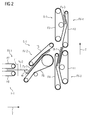
- the stacking device which in Fig. 2 is shown, comprises the conveyor belts F5 and F6 and the rollers about which these two conveyor belts F5 and F6 are guided.
- the opening transport path is formed, inter alia, by the conveyor belts F7 and F8.
- This transport path leads to a further transport path, namely the output transport path A-1, which comprises the conveyor belts F1, F2, F3 and F4 and into which a small stack St-1 is transported.
- the mailpieces are deflected as they pass through the stacker.
- the transport direction in which they are transported so is changed by an angle ⁇ , which is preferably between 30 degrees and 60 degrees, z. B. it is equal to 45 degrees.
- a leading mail item Ps-1 is transported by a first conveying device (endless conveyor belt and counter-conveying element) in the old transport direction, namely until the mail item Ps-1 is picked up by a second conveying device FV-2.
- This first conveyor FV-1 comprises in the example of Fig. 2 the conveyor belts F7 and F8.
- a second conveyor FV-2 comprises the conveyor belts F7 and F8.
- the second conveying device FV-2 deflects the mail item Ps-1 by the angle ⁇ in the new conveying direction and still carries the mail item Ps-1 so far that it is no longer taken by the first conveyor FV-1 (with F7 and F8).
- the first conveying device FV-1 stops or slows down the further transport of the preceding mail item Ps-1. For this it is necessary that the mail item Ps-1 is no longer taken from the first conveyor FV-1, because otherwise they would be upset by the two conveyors FV-1 and FV-2.
- the first conveying device FV-1 transports a subsequent mail item Ps-2 until it obliquely meets the stopped leading mail item Ps-1.
- the leading mail item Ps-1 lies during the stop - seen in the old transport direction - in front of an endless conveyor belt F6 of the second conveyor FV-6.
- the impinging subsequent mail item Ps-2 does not bend the stopped leading mail item Ps-1 upon impact, but is deflected because the first conveying apparatus continues to transport the subsequent mail item in the old transport direction until the second conveying apparatus has grasped the subsequent mail item.
- the second conveying device holds the leading and the subsequent mail item. These overlap now at least partially. As a result, a small stack consisting of the preceding mail item Ps-1 and the subsequent mail item Ps-2 is formed.
- the stacking device transports this small stack away in the new transport direction, wherein the second conveyor FV-2 further transports the small stack with Ps-1 and Ps-2.
- the mail items are generally rectangular and therefore each have a - seen in the transport direction - front edge.
- a light barrier Li in the input transport path E-1 is measured, at which time the leading edge of the leading mail piece and at what time the subsequent mailing the light barrier Li passes.
- the transport speeds of the two conveyors FV-1, FV-2 are controlled and are therefore also known.
- the second conveying device FV-2 transports the leading mail item into the new transport direction so far that the leading edge is in a defined position when the trailing edge is no longer caught by the first conveying device.
- the point at which the leading edge of the subsequent mail item strikes the stopped leading mail item therefore has a known and adjustable minimum distance 'from the front edge of the leading mail piece. This distance is preferably as small as possible, so that the total length of the small stack is as small as possible.
- the light barrier Li in the input transport path E-1 also measures the times at which the trailing edges of the two mailings pass through the light barrier Li. From this information and the transport speed of the first conveyor Fv-1 and the above-mentioned distance between the front edge of the leading mail item Ps-1 of the point of impact, the total length of the now formed small stack is calculated.
- the sorting system further has a control device which has read and write access to a data memory.
- a data memory In the data memory for each mail item is stored in each case a record that includes an internal identifier of the mailing, the read delivery address and information about their current position.
- the control device controls the conveyor belts and switches of the system to guide a mail item through the sorting system depending on its state and its delivery address.
- LIST OF REFERENCE NUMBERS reference numeral importance A-1, A-2 Output transport paths B-1, B-2 processing facilities E-1, E-2 Input transport paths E-3 additional input transport path F1, F2, ...
Landscapes
- Engineering & Computer Science (AREA)
- Mechanical Engineering (AREA)
- Sorting Of Articles (AREA)
- Control Of Conveyors (AREA)
Applications Claiming Priority (1)
| Application Number | Priority Date | Filing Date | Title |
|---|---|---|---|
| DE102008018937A DE102008018937A1 (de) | 2008-04-15 | 2008-04-15 | Vorrichtung und Verfahren zum Transport von Gegenständen über sich kreuzende Transportpfade |
Publications (3)
| Publication Number | Publication Date |
|---|---|
| EP2110356A2 true EP2110356A2 (fr) | 2009-10-21 |
| EP2110356A3 EP2110356A3 (fr) | 2011-04-27 |
| EP2110356B1 EP2110356B1 (fr) | 2012-06-13 |
Family
ID=40897366
Family Applications (1)
| Application Number | Title | Priority Date | Filing Date |
|---|---|---|---|
| EP09157729A Not-in-force EP2110356B1 (fr) | 2008-04-15 | 2009-04-09 | Dispositif et procédé de transport d'objets par des chemins de transports croisés |
Country Status (3)
| Country | Link |
|---|---|
| US (1) | US20090255778A1 (fr) |
| EP (1) | EP2110356B1 (fr) |
| DE (1) | DE102008018937A1 (fr) |
Cited By (1)
| Publication number | Priority date | Publication date | Assignee | Title |
|---|---|---|---|---|
| CH703277A1 (de) * | 2010-06-15 | 2011-12-15 | Ferag Ag | Vorrichtung und Verfahren zum Erzeugen von Paketen aus flexiblen, flachen Gegenständen. |
Citations (7)
| Publication number | Priority date | Publication date | Assignee | Title |
|---|---|---|---|---|
| US4552349A (en) | 1982-04-05 | 1985-11-12 | Hall Systems, Inc. | Programmable packaging grid for loop gripper product conveyor system |
| DE19616231A1 (de) | 1995-04-20 | 1996-10-24 | Vaillant Joh Gmbh & Co | Verfahren zum Steuern des Materialflusses von Bauteilen |
| EP0923997A2 (fr) | 1997-12-17 | 1999-06-23 | Elsag Spa | Procédé de collecte et de transport de groupes d'objets postaux partiellement superposés |
| DE10305847B3 (de) | 2003-02-12 | 2004-08-19 | Siemens Ag | Sortiereinrichtung für flache Sendungen |
| DE102004056696B4 (de) | 2004-11-24 | 2006-08-31 | Siemens Ag | Einrichtung zum Vorsortieren von vereinzelten schmalen Sendungen |
| WO2006110486A2 (fr) | 2005-04-07 | 2006-10-19 | Pitney Bowes Inc. | Systeme et procede de macro tri |
| WO2009015503A1 (fr) | 2007-07-30 | 2009-02-05 | Ferag Ag | Système d'assemblage de groupes d'objets plats |
Family Cites Families (39)
| Publication number | Priority date | Publication date | Assignee | Title |
|---|---|---|---|---|
| US2728466A (en) * | 1950-04-04 | 1955-12-27 | California Research Corp | Conveyor control system |
| US3452509A (en) * | 1966-04-11 | 1969-07-01 | Itt | Automatic sorting system for discrete flat articles |
| US3612250A (en) * | 1970-04-06 | 1971-10-12 | Rapistan Inc | Recirculation limit system for conveyors |
| US4058217A (en) * | 1973-05-01 | 1977-11-15 | Unisearch Limited | Automatic article sorting system |
| SU656676A1 (ru) * | 1977-03-15 | 1979-04-15 | Специальное Проектно-Конструкторское Бюро | Устройство дл сортировки предметов |
| US4244672A (en) * | 1979-06-04 | 1981-01-13 | Burroughs Corporation | System for sequencing articles including mail |
| FR2555917B1 (fr) * | 1983-12-02 | 1988-01-15 | Hotchkiss Brandt Sogeme | Machine de tri a debit ameliore |
| US4921109A (en) * | 1985-05-07 | 1990-05-01 | Shibuya Computer Service Kabushiki Kaisha | Card sorting method and apparatus |
| NL8902846A (nl) * | 1989-11-17 | 1991-06-17 | Nederland Ptt | Buffer en buffersysteem voor het tijdelijk opslaan van platte voorwerpen, zoals brieven. |
| DE4000603C5 (de) | 1990-01-11 | 2009-07-02 | Siemens Ag | Verfahren und Vorrichtung zur Zwischenspeicherung von Gegenständen, wie Briefen o.ä. in einem Lesesystem |
| US5119954A (en) * | 1990-03-29 | 1992-06-09 | Bell & Howell Company | Multi-pass sorting machine |
| US5377814A (en) * | 1990-06-20 | 1995-01-03 | Fabri-Check, Inc. | Transport carrier for use in an article sorting system |
| DE4022163A1 (de) * | 1990-07-12 | 1992-01-16 | Licentia Gmbh | Vorrichtung zum aus- u. einschleusen von kleingut aus einem transportband |
| JP2647305B2 (ja) * | 1992-06-19 | 1997-08-27 | 株式会社東芝 | 紙葉類処理装置 |
| CH685992A5 (de) * | 1992-07-22 | 1995-11-30 | Grapha Holding Ag | Einrichtung fur die Verarbeitung von Druckprodukten. |
| EP0654309B1 (fr) * | 1993-11-23 | 1999-09-29 | Elsag Spa | Dispositif d'accumulation de courrier |
| DE9406061U1 (de) * | 1994-04-12 | 1995-08-10 | Mts Modulare Transport Systeme Gmbh, Vomp | Sortieranlage zum Sortieren von einzeln geförderten Gegenständen |
| JP3590998B2 (ja) * | 1994-08-19 | 2004-11-17 | 株式会社日立製作所 | 区分機システム |
| WO1999007487A1 (fr) * | 1997-08-06 | 1999-02-18 | Siemens Aktiengesellschaft | Procede de triage d'envois |
| US6076683A (en) * | 1997-10-29 | 2000-06-20 | Sandvik Sorting Systems, Inc. | Sorter mechanism |
| IT1295970B1 (it) * | 1997-11-14 | 1999-05-28 | Finmeccanica Spa | Metodo di sequenziazione di oggetti postali. |
| US6801821B2 (en) * | 1999-08-03 | 2004-10-05 | Honda Canada Incorporated | Assembly line control system |
| US6516239B1 (en) * | 1999-08-03 | 2003-02-04 | Honda Of Canada Incorporated | Assembly line control system |
| DE19938470A1 (de) * | 1999-08-13 | 2001-02-15 | Wf Logistik Gmbh | Verfahren zum Sortieren einer Gruppe von Gegenständen |
| US6412621B1 (en) * | 1999-10-21 | 2002-07-02 | Rapistan Systems Advertising Corp. | Conveyors system with volume sharing |
| FR2799995B1 (fr) * | 1999-10-26 | 2003-08-01 | Mannesmann Dematic Postal Automation Sa | Procede et machine pour fusionner des lots d'objets ordonnes notamment des lots d'articles de courrier |
| DE10039394C1 (de) * | 2000-08-11 | 2001-09-13 | Mts Modulare Transp Systeme Gm | Sortierverfahren, Sortieranlage und Sortiersystem |
| DE50100207D1 (de) * | 2000-11-08 | 2003-06-05 | Denipro Ag Weinfelden | Verfahren und Einrichtung zum Lagern und Ausliefern von Gegenständen |
| US6610954B2 (en) * | 2001-02-26 | 2003-08-26 | At&C Co., Ltd. | System for sorting commercial articles and method therefor |
| US7353955B2 (en) * | 2003-07-16 | 2008-04-08 | Siemens Energy & Automation, Inc. | Baggage screening system and method |
| US20070003396A1 (en) * | 2003-09-03 | 2007-01-04 | Siemens Aktiengesellschaft | System and method for extracting articles from a slot |
| US7185888B2 (en) * | 2004-03-29 | 2007-03-06 | Palo Alto Research Center Incorporated | Rotational jam clearance apparatus |
| US7728245B2 (en) * | 2004-05-10 | 2010-06-01 | Siemens Industry, Inc. | Multi-machine mail sorting system |
| US7414218B2 (en) * | 2004-08-16 | 2008-08-19 | Lockheed Martin Corporation | Cross circulation mail sorter stacker design with dual ported input, and method of operating the same |
| EP1868742B1 (fr) * | 2005-03-21 | 2009-08-26 | Siemens Aktiengesellschaft | Systeme et procede de traitement de courrier |
| US20070075000A1 (en) * | 2005-09-30 | 2007-04-05 | Lockheed Martin Corporation | Sort mechanism and method of use |
| US20070090028A1 (en) * | 2005-10-25 | 2007-04-26 | Lockheed Martin Corporation | Sort mechanism and method of use |
| DE102006030096A1 (de) * | 2006-06-28 | 2008-01-03 | Siemens Ag | Sortiersystem mit Speichermodulen für flache Poststücke mit Last-In/First-Out-Betrieb und verbesserter Adresszuordnung |
| US8155002B2 (en) * | 2006-09-21 | 2012-04-10 | Arris Group, Inc. | Method for automatically inflating the receive window size in TCP connections |
-
2008
- 2008-04-15 DE DE102008018937A patent/DE102008018937A1/de not_active Withdrawn
-
2009
- 2009-04-09 EP EP09157729A patent/EP2110356B1/fr not_active Not-in-force
- 2009-04-15 US US12/423,837 patent/US20090255778A1/en not_active Abandoned
Patent Citations (7)
| Publication number | Priority date | Publication date | Assignee | Title |
|---|---|---|---|---|
| US4552349A (en) | 1982-04-05 | 1985-11-12 | Hall Systems, Inc. | Programmable packaging grid for loop gripper product conveyor system |
| DE19616231A1 (de) | 1995-04-20 | 1996-10-24 | Vaillant Joh Gmbh & Co | Verfahren zum Steuern des Materialflusses von Bauteilen |
| EP0923997A2 (fr) | 1997-12-17 | 1999-06-23 | Elsag Spa | Procédé de collecte et de transport de groupes d'objets postaux partiellement superposés |
| DE10305847B3 (de) | 2003-02-12 | 2004-08-19 | Siemens Ag | Sortiereinrichtung für flache Sendungen |
| DE102004056696B4 (de) | 2004-11-24 | 2006-08-31 | Siemens Ag | Einrichtung zum Vorsortieren von vereinzelten schmalen Sendungen |
| WO2006110486A2 (fr) | 2005-04-07 | 2006-10-19 | Pitney Bowes Inc. | Systeme et procede de macro tri |
| WO2009015503A1 (fr) | 2007-07-30 | 2009-02-05 | Ferag Ag | Système d'assemblage de groupes d'objets plats |
Cited By (2)
| Publication number | Priority date | Publication date | Assignee | Title |
|---|---|---|---|---|
| CH703277A1 (de) * | 2010-06-15 | 2011-12-15 | Ferag Ag | Vorrichtung und Verfahren zum Erzeugen von Paketen aus flexiblen, flachen Gegenständen. |
| US8733752B2 (en) | 2010-06-15 | 2014-05-27 | Ferag Ag | Apparatus and method for producing packs of flexible flat objects |
Also Published As
| Publication number | Publication date |
|---|---|
| US20090255778A1 (en) | 2009-10-15 |
| DE102008018937A1 (de) | 2009-10-29 |
| EP2110356A3 (fr) | 2011-04-27 |
| EP2110356B1 (fr) | 2012-06-13 |
Similar Documents
| Publication | Publication Date | Title |
|---|---|---|
| EP2741867B1 (fr) | Installation et procédé de tri permettant de trier ensemble des objets de type différent | |
| EP1727626B1 (fr) | Procede et dispositif de tri d'envois postaux plats | |
| EP0853984B1 (fr) | Dispositif et procédé de transfert d'articles à trier en une rangée ordonnée | |
| EP1509341B1 (fr) | Procede et dispositif de traitement d'envois plats | |
| EP2085152B1 (fr) | Procédé et dispositif de tri d'objets plats dans plusieurs passes de tri | |
| EP0834354B1 (fr) | Dispositif et procédé de transfert de colis à trier selon une rangée ordonnée | |
| DE3010793A1 (de) | Vorrichtung zum behandeln von blaettern | |
| EP2253390A1 (fr) | Procédé et dispositif destiné au tri d'objets postaux | |
| DE102010010375A1 (de) | Verfahren und Vorrichtung zur Richtungsumkehr beim Transport von Gegenständen | |
| EP2316580A1 (fr) | Dispositif et procédé de traitement d'objets ayant différentes dimensions | |
| EP2065325A2 (fr) | Procédé et dispositif de réunion de deux flux d'objets | |
| DE60035942T2 (de) | Verfahren zur Zuführung von Umschlägen an eine Kuvertiereinrichtung | |
| DE102010035472A1 (de) | Verfahren und Vorrichtung zum Transport von Gegenständen in mehreren parallelen Pufferstrecken | |
| EP2067535B1 (fr) | Procédé etdispositif de tri d'envois postaux plats | |
| DE102011004091A1 (de) | Verfahren und Vorrichtung zum Sortieren von flachen Gegenständen mit Lückenver derung | |
| EP2110356B1 (fr) | Dispositif et procédé de transport d'objets par des chemins de transports croisés | |
| EP1218269B1 (fr) | Procede et dispositif de correction des intervalles entre des envois postaux | |
| EP3183071B1 (fr) | Dispositif et procédé de tri d'objets | |
| EP0728536A1 (fr) | Dispositif et procédé de traitement d'envois postaux pourvus d'adresses d'expédition | |
| DE102007058581B4 (de) | Sortiersystem für flache Postsendungen | |
| EP1930268A2 (fr) | Procédé et dispositif de détournement d'objets plats | |
| DE102021131467A1 (de) | Vorrichtung zum Sortieren von Poststücken und Verfahren zum Zuführen eines Poststücks zu einer Sortiervorrichtung durch eine Zufuhrvorrichtung | |
| DE102009016559A1 (de) | Verfahren und Vorrichtung zum Sortieren von flachen Gegenständen | |
| EP2078569B1 (fr) | Procédé et dispositif de tri dans le sens de la marche de courriers plats | |
| DE202021106530U1 (de) | Vorrichtung zum Sortieren von Poststücken und Steuereinrichtung für eine Vorrichtung umfassend eine Sortiervorrichtung und eine Zufuhrvorrichtung |
Legal Events
| Date | Code | Title | Description |
|---|---|---|---|
| PUAI | Public reference made under article 153(3) epc to a published international application that has entered the european phase |
Free format text: ORIGINAL CODE: 0009012 |
|
| AK | Designated contracting states |
Kind code of ref document: A2 Designated state(s): AT BE BG CH CY CZ DE DK EE ES FI FR GB GR HR HU IE IS IT LI LT LU LV MC MK MT NL NO PL PT RO SE SI SK TR |
|
| TPAC | Observations by third parties |
Free format text: ORIGINAL CODE: EPIDOSNTIPA |
|
| PUAL | Search report despatched |
Free format text: ORIGINAL CODE: 0009013 |
|
| 17P | Request for examination filed |
Effective date: 20110221 |
|
| AK | Designated contracting states |
Kind code of ref document: A3 Designated state(s): AT BE BG CH CY CZ DE DK EE ES FI FR GB GR HR HU IE IS IT LI LT LU LV MC MK MT NL NO PL PT RO SE SI SK TR |
|
| GRAP | Despatch of communication of intention to grant a patent |
Free format text: ORIGINAL CODE: EPIDOSNIGR1 |
|
| RIC1 | Information provided on ipc code assigned before grant |
Ipc: B65H 29/66 20060101ALI20111005BHEP Ipc: B65H 29/60 20060101AFI20111005BHEP |
|
| RIN1 | Information on inventor provided before grant (corrected) |
Inventor name: BERDELLE-HILGE, DR. PETER |
|
| GRAS | Grant fee paid |
Free format text: ORIGINAL CODE: EPIDOSNIGR3 |
|
| GRAA | (expected) grant |
Free format text: ORIGINAL CODE: 0009210 |
|
| AK | Designated contracting states |
Kind code of ref document: B1 Designated state(s): AT BE BG CH CY CZ DE DK EE ES FI FR GB GR HR HU IE IS IT LI LT LU LV MC MK MT NL NO PL PT RO SE SI SK TR |
|
| REG | Reference to a national code |
Ref country code: GB Ref legal event code: FG4D Free format text: NOT ENGLISH |
|
| REG | Reference to a national code |
Ref country code: AT Ref legal event code: REF Ref document number: 561882 Country of ref document: AT Kind code of ref document: T Effective date: 20120615 Ref country code: CH Ref legal event code: NV Representative=s name: SIEMENS SCHWEIZ AG Ref country code: CH Ref legal event code: EP |
|
| REG | Reference to a national code |
Ref country code: IE Ref legal event code: FG4D Free format text: LANGUAGE OF EP DOCUMENT: GERMAN |
|
| REG | Reference to a national code |
Ref country code: DE Ref legal event code: R096 Ref document number: 502009003789 Country of ref document: DE Effective date: 20120809 |
|
| REG | Reference to a national code |
Ref country code: NL Ref legal event code: VDEP Effective date: 20120613 |
|
| PG25 | Lapsed in a contracting state [announced via postgrant information from national office to epo] |
Ref country code: FI Free format text: LAPSE BECAUSE OF FAILURE TO SUBMIT A TRANSLATION OF THE DESCRIPTION OR TO PAY THE FEE WITHIN THE PRESCRIBED TIME-LIMIT Effective date: 20120613 Ref country code: CY Free format text: LAPSE BECAUSE OF FAILURE TO SUBMIT A TRANSLATION OF THE DESCRIPTION OR TO PAY THE FEE WITHIN THE PRESCRIBED TIME-LIMIT Effective date: 20120613 Ref country code: LT Free format text: LAPSE BECAUSE OF FAILURE TO SUBMIT A TRANSLATION OF THE DESCRIPTION OR TO PAY THE FEE WITHIN THE PRESCRIBED TIME-LIMIT Effective date: 20120613 Ref country code: NO Free format text: LAPSE BECAUSE OF FAILURE TO SUBMIT A TRANSLATION OF THE DESCRIPTION OR TO PAY THE FEE WITHIN THE PRESCRIBED TIME-LIMIT Effective date: 20120913 Ref country code: SE Free format text: LAPSE BECAUSE OF FAILURE TO SUBMIT A TRANSLATION OF THE DESCRIPTION OR TO PAY THE FEE WITHIN THE PRESCRIBED TIME-LIMIT Effective date: 20120613 |
|
| REG | Reference to a national code |
Ref country code: LT Ref legal event code: MG4D Effective date: 20120627 |
|
| PG25 | Lapsed in a contracting state [announced via postgrant information from national office to epo] |
Ref country code: HR Free format text: LAPSE BECAUSE OF FAILURE TO SUBMIT A TRANSLATION OF THE DESCRIPTION OR TO PAY THE FEE WITHIN THE PRESCRIBED TIME-LIMIT Effective date: 20120613 Ref country code: GR Free format text: LAPSE BECAUSE OF FAILURE TO SUBMIT A TRANSLATION OF THE DESCRIPTION OR TO PAY THE FEE WITHIN THE PRESCRIBED TIME-LIMIT Effective date: 20120914 Ref country code: LV Free format text: LAPSE BECAUSE OF FAILURE TO SUBMIT A TRANSLATION OF THE DESCRIPTION OR TO PAY THE FEE WITHIN THE PRESCRIBED TIME-LIMIT Effective date: 20120613 Ref country code: SI Free format text: LAPSE BECAUSE OF FAILURE TO SUBMIT A TRANSLATION OF THE DESCRIPTION OR TO PAY THE FEE WITHIN THE PRESCRIBED TIME-LIMIT Effective date: 20120613 |
|
| PG25 | Lapsed in a contracting state [announced via postgrant information from national office to epo] |
Ref country code: SK Free format text: LAPSE BECAUSE OF FAILURE TO SUBMIT A TRANSLATION OF THE DESCRIPTION OR TO PAY THE FEE WITHIN THE PRESCRIBED TIME-LIMIT Effective date: 20120613 Ref country code: IS Free format text: LAPSE BECAUSE OF FAILURE TO SUBMIT A TRANSLATION OF THE DESCRIPTION OR TO PAY THE FEE WITHIN THE PRESCRIBED TIME-LIMIT Effective date: 20121013 Ref country code: CZ Free format text: LAPSE BECAUSE OF FAILURE TO SUBMIT A TRANSLATION OF THE DESCRIPTION OR TO PAY THE FEE WITHIN THE PRESCRIBED TIME-LIMIT Effective date: 20120613 Ref country code: RO Free format text: LAPSE BECAUSE OF FAILURE TO SUBMIT A TRANSLATION OF THE DESCRIPTION OR TO PAY THE FEE WITHIN THE PRESCRIBED TIME-LIMIT Effective date: 20120613 Ref country code: EE Free format text: LAPSE BECAUSE OF FAILURE TO SUBMIT A TRANSLATION OF THE DESCRIPTION OR TO PAY THE FEE WITHIN THE PRESCRIBED TIME-LIMIT Effective date: 20120613 |
|
| PG25 | Lapsed in a contracting state [announced via postgrant information from national office to epo] |
Ref country code: PT Free format text: LAPSE BECAUSE OF FAILURE TO SUBMIT A TRANSLATION OF THE DESCRIPTION OR TO PAY THE FEE WITHIN THE PRESCRIBED TIME-LIMIT Effective date: 20121015 Ref country code: IT Free format text: LAPSE BECAUSE OF FAILURE TO SUBMIT A TRANSLATION OF THE DESCRIPTION OR TO PAY THE FEE WITHIN THE PRESCRIBED TIME-LIMIT Effective date: 20120613 Ref country code: PL Free format text: LAPSE BECAUSE OF FAILURE TO SUBMIT A TRANSLATION OF THE DESCRIPTION OR TO PAY THE FEE WITHIN THE PRESCRIBED TIME-LIMIT Effective date: 20120613 |
|
| RAP2 | Party data changed (patent owner data changed or rights of a patent transferred) |
Owner name: SIEMENS AKTIENGESELLSCHAFT |
|
| PG25 | Lapsed in a contracting state [announced via postgrant information from national office to epo] |
Ref country code: NL Free format text: LAPSE BECAUSE OF FAILURE TO SUBMIT A TRANSLATION OF THE DESCRIPTION OR TO PAY THE FEE WITHIN THE PRESCRIBED TIME-LIMIT Effective date: 20120613 |
|
| PLBE | No opposition filed within time limit |
Free format text: ORIGINAL CODE: 0009261 |
|
| STAA | Information on the status of an ep patent application or granted ep patent |
Free format text: STATUS: NO OPPOSITION FILED WITHIN TIME LIMIT |
|
| PG25 | Lapsed in a contracting state [announced via postgrant information from national office to epo] |
Ref country code: DK Free format text: LAPSE BECAUSE OF FAILURE TO SUBMIT A TRANSLATION OF THE DESCRIPTION OR TO PAY THE FEE WITHIN THE PRESCRIBED TIME-LIMIT Effective date: 20120613 Ref country code: ES Free format text: LAPSE BECAUSE OF FAILURE TO SUBMIT A TRANSLATION OF THE DESCRIPTION OR TO PAY THE FEE WITHIN THE PRESCRIBED TIME-LIMIT Effective date: 20120924 |
|
| 26N | No opposition filed |
Effective date: 20130314 |
|
| REG | Reference to a national code |
Ref country code: DE Ref legal event code: R097 Ref document number: 502009003789 Country of ref document: DE Effective date: 20130314 |
|
| PG25 | Lapsed in a contracting state [announced via postgrant information from national office to epo] |
Ref country code: BG Free format text: LAPSE BECAUSE OF FAILURE TO SUBMIT A TRANSLATION OF THE DESCRIPTION OR TO PAY THE FEE WITHIN THE PRESCRIBED TIME-LIMIT Effective date: 20120913 |
|
| BERE | Be: lapsed |
Owner name: SIEMENS A.G. Effective date: 20130430 |
|
| PG25 | Lapsed in a contracting state [announced via postgrant information from national office to epo] |
Ref country code: MC Free format text: LAPSE BECAUSE OF FAILURE TO SUBMIT A TRANSLATION OF THE DESCRIPTION OR TO PAY THE FEE WITHIN THE PRESCRIBED TIME-LIMIT Effective date: 20120613 |
|
| REG | Reference to a national code |
Ref country code: CH Ref legal event code: PL |
|
| GBPC | Gb: european patent ceased through non-payment of renewal fee |
Effective date: 20130409 |
|
| REG | Reference to a national code |
Ref country code: IE Ref legal event code: MM4A |
|
| PG25 | Lapsed in a contracting state [announced via postgrant information from national office to epo] |
Ref country code: DE Free format text: LAPSE BECAUSE OF NON-PAYMENT OF DUE FEES Effective date: 20131101 Ref country code: LI Free format text: LAPSE BECAUSE OF NON-PAYMENT OF DUE FEES Effective date: 20130430 Ref country code: GB Free format text: LAPSE BECAUSE OF NON-PAYMENT OF DUE FEES Effective date: 20130409 Ref country code: CH Free format text: LAPSE BECAUSE OF NON-PAYMENT OF DUE FEES Effective date: 20130430 Ref country code: BE Free format text: LAPSE BECAUSE OF NON-PAYMENT OF DUE FEES Effective date: 20130430 |
|
| REG | Reference to a national code |
Ref country code: FR Ref legal event code: ST Effective date: 20131231 |
|
| REG | Reference to a national code |
Ref country code: DE Ref legal event code: R119 Ref document number: 502009003789 Country of ref document: DE Effective date: 20131101 |
|
| PG25 | Lapsed in a contracting state [announced via postgrant information from national office to epo] |
Ref country code: FR Free format text: LAPSE BECAUSE OF NON-PAYMENT OF DUE FEES Effective date: 20130430 |
|
| PG25 | Lapsed in a contracting state [announced via postgrant information from national office to epo] |
Ref country code: IE Free format text: LAPSE BECAUSE OF NON-PAYMENT OF DUE FEES Effective date: 20130409 |
|
| PG25 | Lapsed in a contracting state [announced via postgrant information from national office to epo] |
Ref country code: MT Free format text: LAPSE BECAUSE OF FAILURE TO SUBMIT A TRANSLATION OF THE DESCRIPTION OR TO PAY THE FEE WITHIN THE PRESCRIBED TIME-LIMIT Effective date: 20120613 |
|
| REG | Reference to a national code |
Ref country code: AT Ref legal event code: MM01 Ref document number: 561882 Country of ref document: AT Kind code of ref document: T Effective date: 20140409 |
|
| PG25 | Lapsed in a contracting state [announced via postgrant information from national office to epo] |
Ref country code: TR Free format text: LAPSE BECAUSE OF FAILURE TO SUBMIT A TRANSLATION OF THE DESCRIPTION OR TO PAY THE FEE WITHIN THE PRESCRIBED TIME-LIMIT Effective date: 20120613 |
|
| PG25 | Lapsed in a contracting state [announced via postgrant information from national office to epo] |
Ref country code: HU Free format text: LAPSE BECAUSE OF FAILURE TO SUBMIT A TRANSLATION OF THE DESCRIPTION OR TO PAY THE FEE WITHIN THE PRESCRIBED TIME-LIMIT; INVALID AB INITIO Effective date: 20090409 Ref country code: LU Free format text: LAPSE BECAUSE OF NON-PAYMENT OF DUE FEES Effective date: 20130409 Ref country code: MK Free format text: LAPSE BECAUSE OF FAILURE TO SUBMIT A TRANSLATION OF THE DESCRIPTION OR TO PAY THE FEE WITHIN THE PRESCRIBED TIME-LIMIT Effective date: 20120613 |
|
| PG25 | Lapsed in a contracting state [announced via postgrant information from national office to epo] |
Ref country code: AT Free format text: LAPSE BECAUSE OF NON-PAYMENT OF DUE FEES Effective date: 20140409 |