EP2107434A1 - Composant mécanique, en particulier dans le rouage d'un chronomètre mécanique - Google Patents
Composant mécanique, en particulier dans le rouage d'un chronomètre mécanique Download PDFInfo
- Publication number
- EP2107434A1 EP2107434A1 EP08153962A EP08153962A EP2107434A1 EP 2107434 A1 EP2107434 A1 EP 2107434A1 EP 08153962 A EP08153962 A EP 08153962A EP 08153962 A EP08153962 A EP 08153962A EP 2107434 A1 EP2107434 A1 EP 2107434A1
- Authority
- EP
- European Patent Office
- Prior art keywords
- micromechanical component
- component according
- contact
- coating
- escape wheel
- Prior art date
- Legal status (The legal status is an assumption and is not a legal conclusion. Google has not performed a legal analysis and makes no representation as to the accuracy of the status listed.)
- Granted
Links
Images

Classifications
-
- G—PHYSICS
- G04—HOROLOGY
- G04B—MECHANICALLY-DRIVEN CLOCKS OR WATCHES; MECHANICAL PARTS OF CLOCKS OR WATCHES IN GENERAL; TIME PIECES USING THE POSITION OF THE SUN, MOON OR STARS
- G04B15/00—Escapements
- G04B15/14—Component parts or constructional details, e.g. construction of the lever or the escape wheel
Definitions
- the present invention relates to a novel high-precision and friction-optimized micromechanical component, in particular in the train of a mechanical timepiece, according to the preamble of claim 1.
- the present invention relates in particular to such a micromechanical component, which is part of an anchor escapement of a mechanical timepiece.
- the invention relates to a timepiece in which such a micromechanical component is incorporated.
- a mechanical timepiece as is well known as a pocket watch or wristwatch, usually comprises at least one gear train.
- the drive distribution member forms in a conventional mechanical timepiece, the drive distribution member, the inhibition, the transition between the gear train and the oscillator (vibration or time division organ).
- the task of the inhibition is to supply the vibrating organ, the balance, with a tiny amount of energy every time it passes the "dead spot".
- a "dead point” is the position of the balance at which it is nominally at rest, or the amplitude of the balance is nominally 0 ° (zero crossing).
- the balance oscillates evenly on both sides of the dead point with an amplitude ⁇ and releases a tooth of the escape wheel at each zero crossing. This allows the gear train and the hands to turn in small jumps with a regular frequency controlled by the balance.
- the friction between the pallets and the escape wheel poses a problem which affects the accuracy and the life of the movement.
- High friction reduces the amount of energy passed on to the balance; Accuracy and available power reserve are smaller than with low friction.
- the mentioned friction usually leads to a material removal, so wear, at the contact surfaces of pallets and the escape wheel, whereby the accuracy can be reduced and the parts in question must be replaced from time to time.
- the invention has therefore set itself the task of improving the life and also the precision of mechanical movements through a revision of the mechanical components, and in particular the revision of the anchor escapement from the ground up.
- the use of lubricants should be completely avoided, if possible.
- the present invention is defined in the first independent claim, and a timepiece equipped with the new micromechanical component forms the subject of the second independent claim. Particular or preferred embodiments can be found in the dependent claims.
- the invention is based on the basic idea of initially making the friction between the individual micromechanical components as small as possible. This principle results in particular in a micromechanical component, which is part of the anchor escapement, to extend the life and easier maintenance of the timepiece.
- the contact surfaces of the two bodies (of the two micromechanical components) are transferred into a contact line or a contact point.
- the pallets are inclined against the contact surface of the escape wheel tooth, so that not the flat side end face of the escape wheel tooth, but only the upper axis-parallel edge of the tooth rests against the pallet and slides transversely to the direction of the edge on this surface.
- the size of the contact surface between the pallets and the escape wheel tooth is initially greatly reduced.
- the material of the metallic escape wheel must also be replaced by a harder material at the same time. This initially only affects the contact surfaces on the teeth of the escape wheel.
- the "surface" pressure between the two parts increases very sharply, and there is a risk of increased wear on the contact surfaces.
- the invention provides for the contact surfaces on the teeth of the escape wheel to be made by an extremely hard material.
- a hard material coating with diamond, in particular with nanocrystalline diamond offers. Appropriate techniques for forming such extremely hard coatings have recently become known.
- a next step to further reduce the friction in the armature escapement is the complete replacement of the previously existing metal escape wheel by one of a different material such as silicon
- the wear resistance of the mentioned contact surfaces can be further increased, for example, by a suitable coating.
- a hard material coating can be used, with a silicon oxide such as SiO 2 or a non-stoichiometric oxide having the formula Si x O y , where x and y are integers, as well as silicon carbides, silicon nitrides or diamond are particularly suitable. It should be emphasized in particular that finely crystalline or nanocrystalline and also amorphous coatings prove to be particularly suitable as a wear protection layer.
- the aim is therefore materials that can be deposited either amorphous or have a mean grain size of less than 50nm.
- a sliding friction coefficient of less than 0.2 is sought without the use of lubricants.
- the sliding friction coefficient of highly polished sapphire against steel with the aid of lubricants is about 0.15, ie about 50% -300% more.
- the Gleitreibiere depends on the roughness of the respective surfaces.
- the sliding friction coefficient for many surfaces for example, surfaces of silicon oxide and / or DLC layers (Diamond Like Carbon) highly dependent on the humidity, in diamond this effect is negligible.
- Such a "line” friction can be compared to that of a skate.
- the condition no longer applies to a sliding friction of two surfaces against each other that the frictional force is independent of the surface area of the body in contact. This is based on the fact that in the strictly mathematical sense it is no longer possible to speak of a surface if only one edge, ie a two-dimensional structure, shifts on a surface.
- the contact line so a contact line, which must extend in the direction of movement, located at any point of the previous contact surface, ie centrally, laterally offset or at the edge.
- the width of the contact line to be generated generally depends on the production possibilities; a width of about 50 microns is considered sufficient for the reduction of friction.
- at point-shaped contact points can easily be a contact pressure (pressure) p result, which is above the critical stress fracture of the hard material layer, the hard material thus breaks and the component catastrophically failed.
- the hard material layer must also have a very high mechanical breaking stress which is above the actually occurring compressive stress.
- materials which have a critical compressive stress of more than 0.5 GPa have proven to be suitable. It is particularly preferable to use materials which have a critical compressive stress of more than 2 GPa and in which the fracture stress is additionally isotropic, ie not direction-dependent.
- the critical stress limits and thus also the critical compressive stress are strongly dependent on the crystal orientation. This effect is undesirable and can be avoided, inter alia, by the fact that the crystallites of the hard material layer are statistically oriented.
- the manufacture of the escape wheel made of silicon or diamond can be done by the known modern methods.
- the particular shape on the contact surfaces of the escape wheel namely an edge running in the direction of movement of the pallets, a row of dots or even individual points, can be achieved with photolithographic working methods and structuring technologies of semiconductor technology, such as e.g. generate deep reactive ion etching (so-called DRIE method).
- DRIE method deep reactive ion etching
- the invention also provides another advantage.
- the thermal expansion coefficient is greatly reduced. If it is 10 to 20 ⁇ 10 -6 K -1 for steel and 18 ⁇ 10 -6 K -1 for brass, it has only a value of about 1.1 ⁇ 10 -6 K -1 for diamond and for SiO 2 2 still 0.5 to 0.9 ⁇ 10 -6 K -1 (silicon: 2.6 ⁇ 10 -6 K -1 ). Because of these low values, the parts of the escapement of the present invention maintain their dimensions significantly better than the known escapements, with no excessive temperature variations. Thus, the general functionality of the timepiece is further improved significantly.
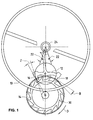
- Fig. 1 schematically this escapement with a balance 10, an armature 12 and an escape wheel 14.
- the armature 12 has an input pallet 16 and an output pallet 18, which come alternately on each of an armature tooth 30 to the plant; the escape wheel is biased by the (not shown) elevator spring on the (also not shown) wheel train in the direction of rotation D.
- the resting surfaces of the anchor pallets 16, 18 do not point to the center of the escape wheel, but are at an angle Z of 12 ° to 15 ° thereto. This angle is called the draw angle.
- the armature 12 in the rest position is reliably pressed by the escape wheel 14 against one of the limiting pins 22. Otherwise, the armature horn in the anchor fork would touch the security roller 24 of the balance 10 every time it is shaken.
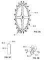
- a first embodiment of the inventive escape wheel is shown.
- the wheel 14-3 has the outer classic Form of an escape wheel and has teeth 30-3, one of which as an enlarged detail B in Fig. 3B is shown.
- 30 raised, roof-shaped contact surfaces 36-3 are each provided with a central ridge 32-3 and 34-3 at the escape wheel tooth.
- This burr which may also be arranged eccentrically without further ado, but has to run in the direction of movement of the pallets (not shown), is preferably produced from an ultra-hard material or coated with a suitable coating (eg with a hard material layer).
- the fillet radius of the free edge of the ridge is less than 25 ⁇ m.
- the escape wheel 14-3 initially consists for example of silicon or a silicon-based material, and at least the inclined surfaces 36-3 and also the ridge 32-3 and 34-3 are made by depositing a hard covering of a silicon oxide, nitride or carbide, made of diamond or another hard material, so that they are extremely smooth and low-friction and are largely insensitive to wear due to their high hardness.
- a hard coating is applied which provides values of HIT hardness (DIN EN ISO 14577) of at least 5 GPa, preferably greater than 10 GPa, and more preferably greater than 50 GPa. These hardness values were determined in nanoindenter experiments.
- the coatings may be nanocrystalline or amorphous.
- Nanocrystalline coatings for example, have an average particle size of less than 100 nm, preferably less than 20 nm.
- the thickness of the coatings should at least reach the value of the rounding diameter of 20 ⁇ m mentioned in this description and at least 100 ⁇ m on flat surfaces.
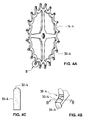
- FIGS. 4A to 4C a second embodiment of the inventive escape wheel is shown.
- the wheel 14-4 has the outer classic shape of an escape wheel and has teeth 30-4, one of which as enlarged detail B in Fig. 4B is shown.
- teeth 30-4 one of which as enlarged detail B in Fig. 4B is shown.
- the cylinder axis extends in the direction of relative movement between the pallets and the escape wheel tooth.
- only the top one deletes and outermost layer 32-4 of the tooth, which again has only a small width extent, namely less than 50 microns when the contact with the pallet is made, on the latter.
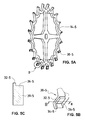
- Figs. 5A to 5C show in an analogous way like that Fig. 3 and 4 a third embodiment of the inventive escape wheel.
- the escape wheel 14-5 in this embodiment is made, for example, of silicon or a silicon-based material by means of a photolithographic or other suitable method, as used, for example, in similar form in semiconductor technology.
- the surfaces 32-5 and 34-5 coming into contact with the pallets are laterally attached to or integrally formed with a support structure 36-5.
- the sectional drawing Fig. 5C is not true to scale; the width of the protruding surface 32-5 is only about 15 to 25 microns to keep the friction on the pallets very low.
- the escape wheel 14-5 may also be made of solid material, after which the surface portions 36-5 have been removed by etching, leaving the ridge 32-5 as a projection. Even with this method, a preferred width of this ridge of only about 15 to 25 microns can be achieved.
- the contact ridge 32-5 may also have a triangular cross-section instead of the illustrated rectangular profile, whereby the contact surface on the teeth of the escape wheel to a contact line (with correspondingly reduced friction) is executed.
- the contact surface on the teeth of the escape wheel to a contact line (with correspondingly reduced friction) is executed.
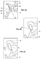
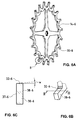
- FIGS. 6A to 6C Another embodiment of the inventive precision anchor escapement is shown in FIGS. 6A to 6C shown. It is an embodiment in which the upper surface 32-6 of the tooth 30-6 is at a certain angle (for example, an angle W between 2 ° and 10 °) to the perpendicular to the lateral surfaces 37-6 and 38-6 is trained. Through this training, a contact line and thus a very small contact area between the escape wheel 14-6 and the pallets of the anchor is achieved.
- a certain angle for example, an angle W between 2 ° and 10 °
- FIG. 7A a ridge 40 of triangular cross-section is mounted on the base 42 of the tooth 30-7, such that one side of the triangle forms the continuation of a side surface of the tooth 30-7. This results in an asymmetrical arrangement of the contact line over the width of the tooth.
- Fig. 7A a ridge 40 of triangular cross-section is mounted on the base 42 of the tooth 30-7, such that one side of the triangle forms the continuation of a side surface of the tooth 30-7.
- FIG. 7B here is a bump 44 of triangular cross-section on the base 46 of the tooth 30-7 ", and the tip of the bump 44 (radius of curvature of, for example, less than about 20 ⁇ m) may be any position over the width of the tooth 30-7".
- the Figures 7C and 7D illustrate two more embodiments of the invention. In Fig. 7C corresponds to the survey 44 'of the survey 44 Fig. 7B , where it is truncated at the top. In Fig. 7D is the survey 49 arched at the top executed with a certain radius of curvature. Even in these two cases, the corresponding contact surfaces are relatively small.
- FIGs. 8A and 8B Another embodiment of the invention is in Figs. 8A and 8B shown.
- the contact surface (always for contact between pallet and escape wheel tooth) is not replaced by a contact line, but by contact points 50 on which the pallet slides, as long as it is in contact with a tooth 30-8 of the escape wheel.
- These contact points 50 may be small cones of diamond inserted into the material of the tooth 30-8 - mostly silicon or a silicon based material - or produced by other techniques.
- these contact points can also be generated in such a way that first of all, for example silicon, an escape wheel geometry with line contact according to one of the preceding FIGS Figures 3-7 is generated and then the component is coated at least on its contact surfaces with a hard material layer.
- This hard material layer is now characterized in that it has a large surface roughness after coating.
- This can be achieved, for example, by the growth of a CVD diamond layer with large diamond crystals, eg polycrystalline diamond with mean grain sizes of more than 2 ⁇ m.
- the protruding crystallites act like mountain peaks and thus act as contact points along the protruding ridge, and the contact points are defined self-aligning.
- the counterpart of this rough point bearing surface should be as smooth as possible, so that increased friction by micro-toothing is possible excluded.
- a nanocrystalline CVD offers itself (CVD - C hemical V apor D eposition - deposition from the gas phase) diamond layer with an average grain diameter of less than 50 nm and a correspondingly low surface roughness (average surface roughness R z) of less than 100 nm.
- Fig. 9A a supervision and in Fig. 9B a side view of a pallet shown 16-9.
- On the front and the bottom of the pallet elongated elevations 30-9 are mounted, which terminate in ridges 32-9; these have a radius of curvature at the top, for example, less than 50 microns.
- These ridges come when running the timer in contact with flat mating surfaces on the escape wheel teeth, which are preferably coated with a hard material and a residual roughness (average roughness R z ) of less than about 2 microns.
- the escape wheel is made of a material such as silicon or diamond, but here with even contact surfaces on the teeth 30.
- the range 16-9 (also the corresponding output range 18-9 of the armature, not shown) according to Figs. 9A and 9B can consist of any dimensionally stable material, wherein the elevations 30-9 turn made of hard material, in particular of silicon or diamond, and wherein the silicon surfaces may be coated with one of the above hard materials.
- the escape wheel 14 is initially made of silicon or a silicon-based material, although other materials such as fiber-reinforced carbon, carbon nanotubes, silicon dioxide, silicon nitride, silicon carbide, diamond, etc., are possible, and the inclined surfaces 36 and also the ridges 32 and 34 are made by depositing a hard surfacing of a silicon oxide nitride or carbide, refined from diamond or another hard material, so that they are extremely smooth and low-friction and are largely resistant to wear due to their great hardness.
- the escape wheel is made of silicon and the contact surfaces with the pallets are first coated with silicon nitride, on which a silicon carbide layer is then deposited.
- the anchor with its pallets of diamond can be made for particularly valuable timepieces. Diamond is in all respects a particularly valuable material for these watch parts because it produces only low frictional forces and is exceptionally smooth, i. less rough, offers surfaces and is extremely resistant to wear due to its hardness.
- the invention can be applied to all known clockwork inhibitions, although in the foregoing only the Swiss lever escapement was discussed.
Landscapes
- Physics & Mathematics (AREA)
- General Physics & Mathematics (AREA)
- Micromachines (AREA)
Priority Applications (1)
| Application Number | Priority Date | Filing Date | Title |
|---|---|---|---|
| EP20080153962 EP2107434B1 (fr) | 2008-04-02 | 2008-04-02 | Chronomètre mécanique |
Applications Claiming Priority (1)
| Application Number | Priority Date | Filing Date | Title |
|---|---|---|---|
| EP20080153962 EP2107434B1 (fr) | 2008-04-02 | 2008-04-02 | Chronomètre mécanique |
Publications (2)
| Publication Number | Publication Date |
|---|---|
| EP2107434A1 true EP2107434A1 (fr) | 2009-10-07 |
| EP2107434B1 EP2107434B1 (fr) | 2013-09-18 |
Family
ID=40225236
Family Applications (1)
| Application Number | Title | Priority Date | Filing Date |
|---|---|---|---|
| EP20080153962 Ceased EP2107434B1 (fr) | 2008-04-02 | 2008-04-02 | Chronomètre mécanique |
Country Status (1)
| Country | Link |
|---|---|
| EP (1) | EP2107434B1 (fr) |
Cited By (13)
| Publication number | Priority date | Publication date | Assignee | Title |
|---|---|---|---|---|
| EP2363762A1 (fr) * | 2010-03-04 | 2011-09-07 | Montres Breguet SA | Pièce d'horlogerie comportant un mouvement mécanique à haute fréquence |
| CH703575A2 (fr) * | 2011-03-22 | 2012-01-13 | Lvmh Swiss Mft Sa | Ancre d'échappement pour montre-bracelet mécanique et assortiment comportant une telle ancre. |
| WO2013011032A1 (fr) * | 2011-07-21 | 2013-01-24 | The Swatch Group Research And Development Ltd | Ensemble fonctionnel de micromecanique |
| EP2581794A1 (fr) * | 2011-10-14 | 2013-04-17 | The Swatch Group Research and Development Ltd. | Ensemble fonctionnel de micromécanique |
| EP2889703A2 (fr) | 2013-12-05 | 2015-07-01 | TGM Developpement SA | Procédé de fabrication d'une pièce mécanique en diamant pour mouvement de montre, et pièce fabriquée selon ce procédé |
| EP2889702A2 (fr) | 2013-12-05 | 2015-07-01 | TGM Developpement SA | Palette d'ancre pour échappement de mouvement de montre, et procédé de fabrication adapté |
| DE102014102081A1 (de) | 2014-02-19 | 2015-08-20 | Damasko Gmbh | Mikromechanisches Bauteil und Verfahren zur Herstellung eines mikromechanischen Bauteils |
| EP3001256A1 (fr) | 2014-09-23 | 2016-03-30 | GFD Gesellschaft für Diamantprodukte mbH | Échappement à ancre |
| EP2727880B1 (fr) | 2012-11-05 | 2016-06-08 | GFD Gesellschaft für Diamantprodukte mbH | Composant micromécanique tridimensionnel chanfreiné pour mouvement d'horlogerie et son procédé de fabrication |
| EP3002637B1 (fr) | 2014-09-29 | 2018-11-28 | Richemont International S.A. | Système horloger avec des propriétés tribologiques améliorées |
| US11520290B2 (en) * | 2018-03-29 | 2022-12-06 | Rolex Sa | Wheel for horology movement |
| EP4246245A1 (fr) * | 2022-03-18 | 2023-09-20 | Flexous Mechanisms IP B.V. | Mouvement pour une montre |
| EP4383011A1 (fr) * | 2022-12-07 | 2024-06-12 | Patek Philippe SA Genève | Pièce de micromécanique horlogère et son procédé de fabrication |
Citations (6)
| Publication number | Priority date | Publication date | Assignee | Title |
|---|---|---|---|---|
| CH342897A (fr) * | 1956-11-08 | 1959-11-30 | Huguenin Pierre Louis | Dispositif d'échappement à ancre pour mouvement d'horlogerie |
| CH372476A (de) * | 1958-08-30 | 1963-10-15 | Ernst Leitz Canada Limited | Lichtstarkes photographisches Objektiv |
| FR1485813A (fr) * | 1966-06-17 | 1967-06-23 | Pforzheimer Uhren Rohwerke | Mouvement de montre pour montres-bracelets |
| US6211599B1 (en) * | 1999-08-03 | 2001-04-03 | Sandia Corporation | Microelectromechanical ratcheting apparatus |
| EP1622826A1 (fr) | 2003-04-17 | 2006-02-08 | GFD Gesellschaft für Diamantprodukte mbH | Composant micromecanique et son procede de production |
| EP1921522A1 (fr) * | 2006-11-13 | 2008-05-14 | ETA SA Manufacture Horlogère Suisse | Agencement pour l'interfaçage mécanique d'un micromoteur MEMS avec une roue horlogère et pièce d'horlogerie comportant cet agencement |
-
2008
- 2008-04-02 EP EP20080153962 patent/EP2107434B1/fr not_active Ceased
Patent Citations (6)
| Publication number | Priority date | Publication date | Assignee | Title |
|---|---|---|---|---|
| CH342897A (fr) * | 1956-11-08 | 1959-11-30 | Huguenin Pierre Louis | Dispositif d'échappement à ancre pour mouvement d'horlogerie |
| CH372476A (de) * | 1958-08-30 | 1963-10-15 | Ernst Leitz Canada Limited | Lichtstarkes photographisches Objektiv |
| FR1485813A (fr) * | 1966-06-17 | 1967-06-23 | Pforzheimer Uhren Rohwerke | Mouvement de montre pour montres-bracelets |
| US6211599B1 (en) * | 1999-08-03 | 2001-04-03 | Sandia Corporation | Microelectromechanical ratcheting apparatus |
| EP1622826A1 (fr) | 2003-04-17 | 2006-02-08 | GFD Gesellschaft für Diamantprodukte mbH | Composant micromecanique et son procede de production |
| EP1921522A1 (fr) * | 2006-11-13 | 2008-05-14 | ETA SA Manufacture Horlogère Suisse | Agencement pour l'interfaçage mécanique d'un micromoteur MEMS avec une roue horlogère et pièce d'horlogerie comportant cet agencement |
Non-Patent Citations (1)
| Title |
|---|
| "Kuchling, Taschenbuch der Physik", 1989, VERLAG HARRI DEUTSCH, pages: 103 |
Cited By (22)
| Publication number | Priority date | Publication date | Assignee | Title |
|---|---|---|---|---|
| US8500323B2 (en) | 2010-03-04 | 2013-08-06 | Montres Breguet S.A. | Timepiece including a high frequency mechanical movement |
| CN102193485A (zh) * | 2010-03-04 | 2011-09-21 | 蒙特雷布勒盖股份有限公司 | 包括高频机械机芯的钟表 |
| JP2011185932A (ja) * | 2010-03-04 | 2011-09-22 | Montres Breguet Sa | 高振動周波数の機械的ムーブメントを含む時計 |
| EP2363763A3 (fr) * | 2010-03-04 | 2011-11-16 | Montres Breguet SA | Pièce d'horlogerie comportant un mouvement mécanique à haute fréquence |
| EP2363762A1 (fr) * | 2010-03-04 | 2011-09-07 | Montres Breguet SA | Pièce d'horlogerie comportant un mouvement mécanique à haute fréquence |
| CH703575A2 (fr) * | 2011-03-22 | 2012-01-13 | Lvmh Swiss Mft Sa | Ancre d'échappement pour montre-bracelet mécanique et assortiment comportant une telle ancre. |
| CH703575A3 (fr) * | 2011-03-22 | 2012-03-15 | Lvmh Swiss Mft Sa | Ancre d'échappement pour montre-bracelet mécanique et assortiment comportant une telle ancre. |
| US9958830B2 (en) | 2011-07-21 | 2018-05-01 | The Swatch Group Research And Development Ltd | Functional micromechanical assembly |
| WO2013011032A1 (fr) * | 2011-07-21 | 2013-01-24 | The Swatch Group Research And Development Ltd | Ensemble fonctionnel de micromecanique |
| EP2581794A1 (fr) * | 2011-10-14 | 2013-04-17 | The Swatch Group Research and Development Ltd. | Ensemble fonctionnel de micromécanique |
| EP2727880B1 (fr) | 2012-11-05 | 2016-06-08 | GFD Gesellschaft für Diamantprodukte mbH | Composant micromécanique tridimensionnel chanfreiné pour mouvement d'horlogerie et son procédé de fabrication |
| EP2889703A2 (fr) | 2013-12-05 | 2015-07-01 | TGM Developpement SA | Procédé de fabrication d'une pièce mécanique en diamant pour mouvement de montre, et pièce fabriquée selon ce procédé |
| EP2889702A2 (fr) | 2013-12-05 | 2015-07-01 | TGM Developpement SA | Palette d'ancre pour échappement de mouvement de montre, et procédé de fabrication adapté |
| DE102014102081A1 (de) | 2014-02-19 | 2015-08-20 | Damasko Gmbh | Mikromechanisches Bauteil und Verfahren zur Herstellung eines mikromechanischen Bauteils |
| WO2015125081A1 (fr) | 2014-02-19 | 2015-08-27 | Damasko Gmbh | Pièce micromécanique avec surface de contact réduite et son procédé de fabrication |
| EP3001256A1 (fr) | 2014-09-23 | 2016-03-30 | GFD Gesellschaft für Diamantprodukte mbH | Échappement à ancre |
| EP3001256B1 (fr) | 2014-09-23 | 2020-09-09 | GFD Gesellschaft für Diamantprodukte mbH | Échappement à ancre |
| EP3002637B1 (fr) | 2014-09-29 | 2018-11-28 | Richemont International S.A. | Système horloger avec des propriétés tribologiques améliorées |
| US11520290B2 (en) * | 2018-03-29 | 2022-12-06 | Rolex Sa | Wheel for horology movement |
| EP4246245A1 (fr) * | 2022-03-18 | 2023-09-20 | Flexous Mechanisms IP B.V. | Mouvement pour une montre |
| WO2023175194A1 (fr) | 2022-03-18 | 2023-09-21 | Flexous Mechanisms Ip B.V. | Mouvement pour montre |
| EP4383011A1 (fr) * | 2022-12-07 | 2024-06-12 | Patek Philippe SA Genève | Pièce de micromécanique horlogère et son procédé de fabrication |
Also Published As
| Publication number | Publication date |
|---|---|
| EP2107434B1 (fr) | 2013-09-18 |
Similar Documents
| Publication | Publication Date | Title |
|---|---|---|
| EP2107434B1 (fr) | Chronomètre mécanique | |
| EP2511229B1 (fr) | Composant micromécanique doté de flancs renforcés | |
| EP2037335B1 (fr) | Ancre pour échappement d'horlogerie | |
| DE69909236T2 (de) | Koaxiale Ankerhemmung | |
| EP3101484A1 (fr) | Systeme oscillant mecanique pour montres et procede de fabrication d'un systeme oscillant mecanique pour montres | |
| DE102011109220A1 (de) | Schwingkörper, mechanisches Schwingsystem für Armbanduhren mit einem solchen Schwingkörper sowie Uhr mit einem derartigen Schwingsystem | |
| EP2727880B2 (fr) | Composant micromécanique tridimensionnel chanfreiné et son procédé de fabrication | |
| DE102008061182A1 (de) | Verfahren zum Herstellen eines Mikrobauteils | |
| DE102008029429A1 (de) | Verfahren zum Herstellen von mechanischen Funktionselementen für Uhrwerke sowie nach diesem Verfahren hergestelltes Funktionselement | |
| EP2236455A1 (fr) | Composant micromécanique avec une usure réduite | |
| DE102007000607A1 (de) | Gewindefurchende Schraube | |
| DE102013104248B3 (de) | Verfahren zur Herstellung einer Spiralfeder für mechanische Uhrwerke | |
| EP1233314A1 (fr) | Mouvement d'horlogerie | |
| EP3001256B2 (fr) | Échappement à ancre | |
| CH702171A2 (de) | Uhrenbestandteil und Uhr. | |
| DE112004001036T5 (de) | Diamantscheibe und Ritzvorrichtung | |
| DE202013006409U1 (de) | Zeitmesstechnischer Mechanismus für mikrometrische Verlagerung | |
| DE102014102081A1 (de) | Mikromechanisches Bauteil und Verfahren zur Herstellung eines mikromechanischen Bauteils | |
| EP4180879A1 (fr) | Module micromécanique, son procédé de fabrication et son utilisation | |
| DE102010006790A1 (de) | Mechanisches Schwingsystem für Uhren sowie Funktionselement für Uhren | |
| DE69823484T2 (de) | Bauteil aus Hartmaterial für eine Uhr | |
| DE10231662A1 (de) | Ring | |
| DE102009031841A1 (de) | Mechanisches Schwingsystem für Uhren, Spiralfeder, Schwingkörper sowie Federhalterklotz für ein Schwingsystem | |
| WO2021043566A1 (fr) | Élément de retenue pour une prothèse dentaire amovible, dispositif de prothèse dentaire avec prothèse dentaire amovible, et procédé de réglage du serrage par friction d'une prothèse dentaire amovible | |
| DE102010020792A1 (de) | Mechanisches Schwingsystem für Uhren, Spiralfeder, Schwingkörper sowie Federhalterklotz für ein Schwingsystem |
Legal Events
| Date | Code | Title | Description |
|---|---|---|---|
| PUAI | Public reference made under article 153(3) epc to a published international application that has entered the european phase |
Free format text: ORIGINAL CODE: 0009012 |
|
| AK | Designated contracting states |
Kind code of ref document: A1 Designated state(s): AT BE BG CH CY CZ DE DK EE ES FI FR GB GR HR HU IE IS IT LI LT LU LV MC MT NL NO PL PT RO SE SI SK TR |
|
| AX | Request for extension of the european patent |
Extension state: AL BA MK RS |
|
| 17P | Request for examination filed |
Effective date: 20091210 |
|
| 17Q | First examination report despatched |
Effective date: 20100421 |
|
| AKX | Designation fees paid |
Designated state(s): CH DE FR IT LI |
|
| RTI1 | Title (correction) |
Free format text: MECHANICAL TIMER |
|
| GRAP | Despatch of communication of intention to grant a patent |
Free format text: ORIGINAL CODE: EPIDOSNIGR1 |
|
| GRAP | Despatch of communication of intention to grant a patent |
Free format text: ORIGINAL CODE: EPIDOSNIGR1 |
|
| GRAS | Grant fee paid |
Free format text: ORIGINAL CODE: EPIDOSNIGR3 |
|
| GRAA | (expected) grant |
Free format text: ORIGINAL CODE: 0009210 |
|
| AK | Designated contracting states |
Kind code of ref document: B1 Designated state(s): CH DE FR IT LI |
|
| REG | Reference to a national code |
Ref country code: CH Ref legal event code: EP |
|
| REG | Reference to a national code |
Ref country code: DE Ref legal event code: R096 Ref document number: 502008010679 Country of ref document: DE Effective date: 20131114 |
|
| REG | Reference to a national code |
Ref country code: CH Ref legal event code: NV Representative=s name: BOVARD AG, CH |
|
| REG | Reference to a national code |
Ref country code: DE Ref legal event code: R097 Ref document number: 502008010679 Country of ref document: DE |
|
| PLBE | No opposition filed within time limit |
Free format text: ORIGINAL CODE: 0009261 |
|
| STAA | Information on the status of an ep patent application or granted ep patent |
Free format text: STATUS: NO OPPOSITION FILED WITHIN TIME LIMIT |
|
| 26N | No opposition filed |
Effective date: 20140619 |
|
| REG | Reference to a national code |
Ref country code: DE Ref legal event code: R097 Ref document number: 502008010679 Country of ref document: DE Effective date: 20140619 |
|
| REG | Reference to a national code |
Ref country code: FR Ref legal event code: PLFP Year of fee payment: 8 |
|
| REG | Reference to a national code |
Ref country code: FR Ref legal event code: PLFP Year of fee payment: 9 |
|
| REG | Reference to a national code |
Ref country code: FR Ref legal event code: PLFP Year of fee payment: 10 |
|
| PGFP | Annual fee paid to national office [announced via postgrant information from national office to epo] |
Ref country code: FR Payment date: 20170419 Year of fee payment: 10 Ref country code: DE Payment date: 20170419 Year of fee payment: 10 |
|
| PGFP | Annual fee paid to national office [announced via postgrant information from national office to epo] |
Ref country code: IT Payment date: 20170420 Year of fee payment: 10 |
|
| REG | Reference to a national code |
Ref country code: DE Ref legal event code: R119 Ref document number: 502008010679 Country of ref document: DE |
|
| PG25 | Lapsed in a contracting state [announced via postgrant information from national office to epo] |
Ref country code: DE Free format text: LAPSE BECAUSE OF NON-PAYMENT OF DUE FEES Effective date: 20181101 |
|
| PG25 | Lapsed in a contracting state [announced via postgrant information from national office to epo] |
Ref country code: IT Free format text: LAPSE BECAUSE OF NON-PAYMENT OF DUE FEES Effective date: 20180402 Ref country code: FR Free format text: LAPSE BECAUSE OF NON-PAYMENT OF DUE FEES Effective date: 20180430 |
|
| PGFP | Annual fee paid to national office [announced via postgrant information from national office to epo] |
Ref country code: CH Payment date: 20190412 Year of fee payment: 12 |
|
| REG | Reference to a national code |
Ref country code: CH Ref legal event code: PL |
|
| PG25 | Lapsed in a contracting state [announced via postgrant information from national office to epo] |
Ref country code: CH Free format text: LAPSE BECAUSE OF NON-PAYMENT OF DUE FEES Effective date: 20200430 Ref country code: LI Free format text: LAPSE BECAUSE OF NON-PAYMENT OF DUE FEES Effective date: 20200430 |