EP3101484A1 - Systeme oscillant mecanique pour montres et procede de fabrication d'un systeme oscillant mecanique pour montres - Google Patents
Systeme oscillant mecanique pour montres et procede de fabrication d'un systeme oscillant mecanique pour montres Download PDFInfo
- Publication number
- EP3101484A1 EP3101484A1 EP16165465.2A EP16165465A EP3101484A1 EP 3101484 A1 EP3101484 A1 EP 3101484A1 EP 16165465 A EP16165465 A EP 16165465A EP 3101484 A1 EP3101484 A1 EP 3101484A1
- Authority
- EP
- European Patent Office
- Prior art keywords
- balance spring
- spring
- balance
- silicon
- vibration system
- Prior art date
- Legal status (The legal status is an assumption and is not a legal conclusion. Google has not performed a legal analysis and makes no representation as to the accuracy of the status listed.)
- Withdrawn
Links
- 238000004519 manufacturing process Methods 0.000 title claims abstract description 11
- 238000000034 method Methods 0.000 title claims description 13
- 230000010358 mechanical oscillation Effects 0.000 title 2
- 239000002210 silicon-based material Substances 0.000 claims abstract description 12
- 238000004804 winding Methods 0.000 claims abstract description 11
- XUIMIQQOPSSXEZ-UHFFFAOYSA-N Silicon Chemical compound [Si] XUIMIQQOPSSXEZ-UHFFFAOYSA-N 0.000 claims description 18
- 229910052710 silicon Inorganic materials 0.000 claims description 18
- 239000010703 silicon Substances 0.000 claims description 16
- VYPSYNLAJGMNEJ-UHFFFAOYSA-N Silicium dioxide Chemical compound O=[Si]=O VYPSYNLAJGMNEJ-UHFFFAOYSA-N 0.000 claims description 12
- 229910021420 polycrystalline silicon Inorganic materials 0.000 claims description 12
- 229910052814 silicon oxide Inorganic materials 0.000 claims description 12
- 239000002245 particle Substances 0.000 claims description 8
- 238000005530 etching Methods 0.000 claims description 5
- 238000005520 cutting process Methods 0.000 claims description 3
- 230000000873 masking effect Effects 0.000 claims description 3
- 229910052581 Si3N4 Inorganic materials 0.000 claims description 2
- 239000000919 ceramic Substances 0.000 claims description 2
- HQVNEWCFYHHQES-UHFFFAOYSA-N silicon nitride Chemical compound N12[Si]34N5[Si]62N3[Si]51N64 HQVNEWCFYHHQES-UHFFFAOYSA-N 0.000 claims description 2
- ZOKXTWBITQBERF-UHFFFAOYSA-N Molybdenum Chemical compound [Mo] ZOKXTWBITQBERF-UHFFFAOYSA-N 0.000 description 12
- 238000000576 coating method Methods 0.000 description 11
- 239000011248 coating agent Substances 0.000 description 10
- 229910052750 molybdenum Inorganic materials 0.000 description 10
- 239000011733 molybdenum Substances 0.000 description 10
- 239000000463 material Substances 0.000 description 8
- 238000011161 development Methods 0.000 description 5
- 230000018109 developmental process Effects 0.000 description 5
- 239000002178 crystalline material Substances 0.000 description 4
- NRTOMJZYCJJWKI-UHFFFAOYSA-N Titanium nitride Chemical compound [Ti]#N NRTOMJZYCJJWKI-UHFFFAOYSA-N 0.000 description 3
- 229910045601 alloy Inorganic materials 0.000 description 3
- 239000000956 alloy Substances 0.000 description 3
- 230000005484 gravity Effects 0.000 description 3
- 239000007769 metal material Substances 0.000 description 3
- 239000000853 adhesive Substances 0.000 description 2
- 230000001070 adhesive effect Effects 0.000 description 2
- 230000008021 deposition Effects 0.000 description 2
- 238000000465 moulding Methods 0.000 description 2
- MTPVUVINMAGMJL-UHFFFAOYSA-N trimethyl(1,1,2,2,2-pentafluoroethyl)silane Chemical compound C[Si](C)(C)C(F)(F)C(F)(F)F MTPVUVINMAGMJL-UHFFFAOYSA-N 0.000 description 2
- UONOETXJSWQNOL-UHFFFAOYSA-N tungsten carbide Chemical compound [W+]#[C-] UONOETXJSWQNOL-UHFFFAOYSA-N 0.000 description 2
- 229910001030 Iron–nickel alloy Inorganic materials 0.000 description 1
- 229910001182 Mo alloy Inorganic materials 0.000 description 1
- 230000015572 biosynthetic process Effects 0.000 description 1
- 230000006735 deficit Effects 0.000 description 1
- 238000009713 electroplating Methods 0.000 description 1
- 239000004922 lacquer Substances 0.000 description 1
- 238000001459 lithography Methods 0.000 description 1
- 238000012986 modification Methods 0.000 description 1
- 230000004048 modification Effects 0.000 description 1
- 229910021421 monocrystalline silicon Inorganic materials 0.000 description 1
- 230000010355 oscillation Effects 0.000 description 1
- 230000003647 oxidation Effects 0.000 description 1
- 238000007254 oxidation reaction Methods 0.000 description 1
- 239000010935 stainless steel Substances 0.000 description 1
- 238000003860 storage Methods 0.000 description 1
- 239000002966 varnish Substances 0.000 description 1
Images


Classifications
-
- G—PHYSICS
- G04—HOROLOGY
- G04B—MECHANICALLY-DRIVEN CLOCKS OR WATCHES; MECHANICAL PARTS OF CLOCKS OR WATCHES IN GENERAL; TIME PIECES USING THE POSITION OF THE SUN, MOON OR STARS
- G04B17/00—Mechanisms for stabilising frequency
- G04B17/04—Oscillators acting by spring tension
- G04B17/06—Oscillators with hairsprings, e.g. balance
- G04B17/066—Manufacture of the spiral spring
Definitions
- the invention relates to a mechanical vibration system for watches according to claim 1 and a method for producing a mechanical vibration system for watches
- the European patent application EP 1 445 670 A1 discloses a coil spring of amorphous or crystalline material (silicon wafer).
- the winding cross-section of the spiral spring is 0.015 mm 2 .
- the document does not mention anything regarding the structure of the vibration system and the grain size and other parameters of the balance spring.
- German translation of the European patent specification EP 0 732 635 B1 merely discloses that with the claimed method, a coil spring for clockworks can be made.
- the material of the base plate from which the micromechanical part is structured may be monocrystalline or polycrystalline silicon.
- the document does not mention anything regarding the structure of the vibration system and the grain size and other parameters of the balance spring.
- the international patent application WO 2006/123095 A2 discloses the production of a spiral spring, wherein the individual turns of the coil spring are cut out by means of a laser.
- the coil spring is made of an iron-nickel alloy.
- the object of the invention is to show a vibration system which avoids these disadvantages.
- a mechanical vibration system according to claim 1 is formed.
- a further object of the invention is to provide a method for producing a mechanical vibration system for watches, which avoids these disadvantages. To solve this problem, a method for producing a mechanical vibration system for watches according to claim 8 is formed.
- Functional elements in the context of the invention are in particular those of a mechanical oscillating system for watches and in particular for mechanical watches or wristwatches, namely in particular the spiral and balance spring, the oscillating body or the balance wheel, the shaft of the oscillating body, elements for fixing the balance spring on the oscillating body or Elements for attachment of the balance spring on the shaft of the oscillating body and on a circuit board of the movement, the so-called double disc on the shaft of the oscillating body for deflecting the armature, the armature and the escape wheel.
- Functional elements in the context of the invention are also gears of a movement generally.
- the mechanical vibration system for watches especially for watches, from a balance spring and a balance wheel with a shaft for attachment of the balance spring.
- the balance spring consists of a silicon material (in particular polycrystalline silicon), with a particle size in the range between 10 nm and 50000 nm.
- a winding cross section of the balance spring is 0.001 mm 2 to 0.3 mm 2 .
- the grain size is preferably in the range between 10 nm and 10000 nm.
- the silicon material may be an epitaxially deposited polycrystalline silicon.
- the coefficient of linear expansion of the balance spring is less than 8x10 -6 / K.
- the balance spring is provided on the outer surface of its windings with a thermally generated layer of silicon oxide.
- This layer has a maximum thickness of 4 microns, preferably of a maximum of 3 microns or smaller.
- the silicon material is e.g. a polycrystalline silicon which is epitaxially deposited and from which the wafer is formed.
- the turns of the balance spring are formed by cutting and / or etching from the wafer by means of a masking and etching technique.
- the balance spring is suitably secured to the shaft, and an outboard end of the balance spring is held by a spring retainer block on a spring retainer adjustable by pivoting about an axis of the balance wheel.
- the invention is based inter alia on the finding that a high accuracy, in particular a temperature-independent accuracy in a particularly simple manner in a mechanical vibration system with a balance spring of a non-metallic crystalline material having a particle size in the range between 10 nm and 50 000 nm and with a thermal expansion coefficient smaller 8 10 "7K and / or silicon by using molybdenum (Mo) for the vibrating body and the balance wheel is accessible, and in particular even at greatly reduced thickness of a silicon oxide coating of the balance spring.
- Mo molybdenum
- the oscillating body or balance wheel for example, designed so that the adjusting elements are held by clipping or latching on the oscillating body or on the inside of the balance wheel or a ring of the balance wheel, and / or that the oscillating body of molybdenum or a molybdenum in made of a high proportion alloy, wherein the aforementioned features may be used individually or in any combination.
- the coil spring body is provided in the region of its outer end with a multi-wave section, wherein the coil spring (balance spring) is executed in a further development of the invention, for example, that of silicon and / or that it is made of polycrystalline silicon or a silicon ceramic, eg of silicon nitride, wherein the aforementioned features of the coil spring may be used individually or in any combination.
- the balance spring 2 is made of silicon, preferably made of polycrystalline silicon.
- the balance spring 2 is produced for example from a non-metallic crystalline material having a particle size in the range between 10 nm and 50,000 nm, preferably between 10 nm and 10,000 nm.
- the non-metallic crystalline or sintered material has a coefficient of thermal expansion less than 8 10 -6 / K or the balance spring 2 is using a wafer made of this material or silicon, for example by cutting and / or etching (masking and etching).
- the wafer is produced, for example, by epitaxial deposition of silicon.
- the cross-sectional area of the spring coil is for example 0.001 mm 2 - 0.01 mm 2 .
- the balance spring 2 is provided on the outer surface of its turns with a e.g. provided thermally generated layer of silicon oxide. This layer has a maximum thickness of 4 microns, preferably of at most 3 microns or smaller.
- the oscillating mass or oscillating body i. the oscillating or balance wheel 3, which has, for example, the spoked wheel-like shape usual for such wheels, is made of molybdenum or of an alloy with a high molybdenum content.
- the combination of silicon (for the balance spring 2) and molybdenum (for the balance wheel 3) provides an optimally temperature compensated mechanical vibration system, i. a mechanical vibration system whose gear or frequency accuracy in particular is independent of temperature changes.
- FIG. 2 shows the coil spring 2 again in an individual representation.
- a special feature of this coil spring is that in the area of its outer spring end at 2.1 is repeatedly wavy executed. This area results in an improved, very uniform vibration behavior of the spiral spring 2.
- the spiral spring 2 with the section 2.1 is advantageously also for vibration systems of watches, especially watches, used in which the vibration mass is carried out differently than described above.
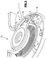
- FIG. 3 shows a perspective view of a vibrating system 1 a with the coil spring 2a and the oscillating or balance wheel 3a.
- the balance spring 2a and the balance wheel 3a are made of the same material and / or in the same manner as described above for the coil spring 2 and the balance wheel 3.
- the balance wheel 3a is designed spoke-like, consisting of an outer ring 4, four radially extending from the ring 4 inwardly extending spokes 5 and a central hub portion 6, which has the opening 6.1 for attachment of the balance shaft and integral with the spokes 5 and the outer ring 4 is made.
- the outer ring 4 is formed on its inside with a circumferential groove 7 and between the spokes 5 each having a fork-like attachment portion 8.
- an adjusting element 9 which is integrally formed from a non-magnetic metallic material, e.g. made of molybdenum or of a corrosion-resistant steel.
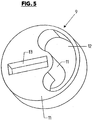
- the adjusting elements 9 consist of a circular-disk-shaped body 10 with a pin 11 which is arranged coaxially with the axis of this body and projecting beyond an end face of the centering element 9 with a circular-cylindrical outer surface. Furthermore, in the body 10 is a continuous, ie at both ends of the Disc-shaped body 10 is provided with an open and arcuately curved recess 12 which extends over an angular range of slightly less than 180 ° about the axis of the centering 9, in such a way that the centering element 9 and its body 10 has a continuous edge at its periphery , the center of gravity of the centering element 9 but offset radially to the axis of the centering element 9.
- each centering element is rotatably provided on a mounting portion 8 about an axis parallel to the axis of the balance wheel 3a, with a certain stiffness in that the respective pin 11 is held by snapping or latching on the fork-like mounting portion 8 and each adjusting element 9 extends on the periphery with its disc-like body 10 in the groove 7, where it is axially secured and bears radially against the bottom of the groove 7.
- each adjusting element 9 is pushed with its pin 11 radially on the associated fork-like mounting portion 8.
- the center of mass of each adjusting element 9 u.a. displaced radially to the axis of the balance wheel 3a and thereby set the dynamic moment of inertia in the desired manner.
- the balance spring 2a is fastened with the inner end in a suitable manner to the balance shaft, not shown.
- the outer end of the coil spring 2a is held on a spring holder block or block 14 of a spring holder 15 which is adjustable by pivoting about the axis of the balance wheel 3a.
- FIG. 6 is made of metallic material spring holder block 14 with a portion 14.1, with which it can be fixed in an opening 16 of the spring holder 15 by clipping or latching, and with a section 14.2 with two fork or clamp arms 17 and 18 executed which form between them a clamping gap 19 in which the coil spring 2a are secured by clamping can.
- the clamping gap 19 is open to the underside facing away from the section 14.1 and also to two opposite end faces of the spring holder block 14 and is bounded by a surface 20 on the side facing the section 14.1.
- the spring holder block 14 In the assembled state of the spring holder block 14 is oriented with its longitudinal extent parallel to the axis of the balance wheel 3a.
- the outer portion of the coil spring 2a is inserted into the clamping gap 19 from the underside of the spring holder block 14 facing away from the section 14.1 or the spring holder 15.
- the coil spring 2a is already held on the spring holder 15 mounted on the spring block 14 such that even a change and adjustment of the effective spring length, which is required for the frequency of the mechanical vibration system 1, by moving the coil spring 2a relative to the spring holder block 14 while maintaining the Clamping connection is possible.
- the connection between the coil spring 2a and the spring holder block 14 is fixed, again using a suitable adhesive or fixing varnish.
- the adjusting elements 9, but in particular the respective spring holder block 14, are preferably manufactured as so-called LIGA parts with the LIGA method known to those skilled in the art, which enables the production of metallic moldings with very small dimensions by the method steps lithography, electroplating and impression molding.
- FIG. 7 schematically the formation of a bearing and / or sliding and / or mounting surface of a functional element 21 reproduced, which consists of silicon, preferably of polycrystalline, for example, epitaxially deposited polycrystalline silicon.
- the bearing and / or sliding and / or mounting surface forming surface 22 of the functional element 21 is formed by a multilayer coating, at least consisting of a directly adjoining the silicon material of the functional element 21 coating 23 of silicon oxide, for example by thermal Oxidation or produced in any other suitable manner.
- the coating 23 is followed by a metallic intermediate layer 24, which preferably consists of titanium nitride and / or titanium carbide and / or tungsten carbide and is applied, for example, in a PVD coating process.
- the intermediate layer 24 may in turn be designed in a multi-layered manner, specifically in several individual layers, for example from the aforementioned materials.
- the intermediate layer 24 is followed by a coating 25 forming the actual outer surface, which is embodied as a DLC coating and produced, for example, by CVD deposition.
- the invention is based on the finding that improved adhesion of the layer 25 to the layer 23 is achieved by the metallic intermediate layer 24, so that the layer 25 is effectively prevented from flaking or loosening by the functional element 21 during assembly and during use of a clock , This is true not only for storage and sliding surfaces, but in particular for mounting surfaces and especially for those with or on which a clamping attachment, for example, a clamping attachment of the spiral or balance spring 2 or the oscillating body to a shaft, etc.
Landscapes
- Engineering & Computer Science (AREA)
- Manufacturing & Machinery (AREA)
- Physics & Mathematics (AREA)
- General Physics & Mathematics (AREA)
- Springs (AREA)
- Micromachines (AREA)
Applications Claiming Priority (11)
| Application Number | Priority Date | Filing Date | Title |
|---|---|---|---|
| DE102009007973 | 2009-02-06 | ||
| DE102009013741 | 2009-03-20 | ||
| DE102009025645 | 2009-06-17 | ||
| DE102009030539 | 2009-06-24 | ||
| DE102009031841A DE102009031841A1 (de) | 2009-02-06 | 2009-07-03 | Mechanisches Schwingsystem für Uhren, Spiralfeder, Schwingkörper sowie Federhalterklotz für ein Schwingsystem |
| DE102009050045 | 2009-09-24 | ||
| DE102009048580 | 2009-10-07 | ||
| DE102009060024 | 2009-12-21 | ||
| DE102010004025 | 2010-01-04 | ||
| DE102010005257 | 2010-01-20 | ||
| EP10721923.0A EP2394202B1 (fr) | 2009-02-06 | 2010-02-04 | Système oscillant mécanique pour montres et élément fonctionnel pour montres |
Related Parent Applications (2)
| Application Number | Title | Priority Date | Filing Date |
|---|---|---|---|
| EP10721923.0A Division-Into EP2394202B1 (fr) | 2009-02-06 | 2010-02-04 | Système oscillant mécanique pour montres et élément fonctionnel pour montres |
| EP10721923.0A Division EP2394202B1 (fr) | 2009-02-06 | 2010-02-04 | Système oscillant mécanique pour montres et élément fonctionnel pour montres |
Publications (1)
| Publication Number | Publication Date |
|---|---|
| EP3101484A1 true EP3101484A1 (fr) | 2016-12-07 |
Family
ID=44951556
Family Applications (2)
| Application Number | Title | Priority Date | Filing Date |
|---|---|---|---|
| EP16165465.2A Withdrawn EP3101484A1 (fr) | 2009-02-06 | 2010-02-04 | Systeme oscillant mecanique pour montres et procede de fabrication d'un systeme oscillant mecanique pour montres |
| EP10721923.0A Revoked EP2394202B1 (fr) | 2009-02-06 | 2010-02-04 | Système oscillant mécanique pour montres et élément fonctionnel pour montres |
Family Applications After (1)
| Application Number | Title | Priority Date | Filing Date |
|---|---|---|---|
| EP10721923.0A Revoked EP2394202B1 (fr) | 2009-02-06 | 2010-02-04 | Système oscillant mécanique pour montres et élément fonctionnel pour montres |
Country Status (4)
| Country | Link |
|---|---|
| US (1) | US20110292770A1 (fr) |
| EP (2) | EP3101484A1 (fr) |
| DE (1) | DE202010018420U1 (fr) |
| WO (1) | WO2010088891A2 (fr) |
Families Citing this family (18)
| Publication number | Priority date | Publication date | Assignee | Title |
|---|---|---|---|---|
| WO2010088891A2 (fr) | 2009-02-06 | 2010-08-12 | Konrad Damasko | Système oscillant mécanique pour montres et élément fonctionnel pour montres |
| EP2437126B1 (fr) * | 2010-10-04 | 2019-03-27 | Rolex Sa | Organe regulateur balancier-spiral |
| EP2474871B1 (fr) * | 2011-01-06 | 2017-05-10 | ETA SA Manufacture Horlogère Suisse | Clé de raquette pour balancier spiral |
| EP2511229B1 (fr) * | 2011-04-12 | 2017-03-08 | GFD Gesellschaft für Diamantprodukte mbH | Composant micromécanique doté de flancs renforcés |
| EP2520983A1 (fr) * | 2011-05-03 | 2012-11-07 | Nivarox-FAR S.A. | Barillet comportant des moyens élastiques d'accumulation d'énergie |
| CH704924B1 (de) * | 2011-05-13 | 2015-05-29 | Bucherer Ag | Unruh für eine Uhr sowie Uhr. |
| WO2013092172A1 (fr) * | 2011-12-22 | 2013-06-27 | The Swatch Group Research And Development Ltd | Procédé d'amélioration du pivotement d'un mobile |
| US10372083B2 (en) * | 2012-07-06 | 2019-08-06 | Rolex Sa | Method for treating a surface of a timepiece component, and timepiece component obtained from such a method |
| KR101846802B1 (ko) * | 2012-11-16 | 2018-04-06 | 니바록스-파 에스.에이. | 열적으로 보상된 스프링식 밸런스 공진기용 보상 밸런스 스프링 |
| EP2757424B1 (fr) * | 2013-01-17 | 2018-05-16 | Omega SA | Pièce pour mouvement d'horlogerie |
| EP2757423B1 (fr) * | 2013-01-17 | 2018-07-11 | Omega SA | Pièce pour mouvement d'horlogerie |
| CH707811A2 (fr) | 2013-03-19 | 2014-09-30 | Nivarox Sa | Composant monobloc indémontable d'horlogerie. |
| EP2781968A1 (fr) * | 2013-03-19 | 2014-09-24 | Nivarox-FAR S.A. | Résonateur moins sensible aux variations climatiques |
| CH707808B1 (fr) * | 2013-03-19 | 2017-05-15 | Nivarox Far Sa | Cassette de mécanisme d'horlogerie. |
| CH708429A1 (fr) | 2013-08-19 | 2015-02-27 | Manuf Et Fabrique De Montres Et Chronomètres Ulysse Nardin Le Locle S A | Spiral pour organe réglant de montre mécanique, organe régulateur muni d'un tel spiral, et procédé de réalisation d'un tel spiral. |
| CN106104393A (zh) * | 2014-01-29 | 2016-11-09 | 卡地亚国际股份公司 | 由在其组成中包含硅的陶瓷制成的热补偿的游丝和用于调节游丝的方法 |
| EP3002635B8 (fr) * | 2014-09-29 | 2019-05-22 | Richemont International SA | Procédé de fabrication d'un élément ressort pour mouvement horloger ou autre instrument de précision |
| EP3667433B1 (fr) * | 2018-12-12 | 2023-02-01 | Nivarox-FAR S.A. | Spiral et son procede de fabrication |
Citations (7)
| Publication number | Priority date | Publication date | Assignee | Title |
|---|---|---|---|---|
| EP0732635B1 (fr) | 1995-03-17 | 2000-06-07 | C.S.E.M. Centre Suisse D'electronique Et De Microtechnique Sa | Procédé de réalisation d'une piéce de micro-mécanique |
| DE10127733A1 (de) * | 2001-06-07 | 2003-02-06 | Silicium Energiesysteme E K Dr | Schrauben- oder Spiralfederelemente aus kristallinem, insbesondere einkristallinem Silicium |
| US6621137B1 (en) * | 2000-10-12 | 2003-09-16 | Intel Corporation | MEMS device integrated chip package, and method of making same |
| FR2842313A1 (fr) * | 2002-07-12 | 2004-01-16 | Gideon Levingston | Oscilliateur mecanique (systeme balancier et ressort spiral) en materiaux permettant d'atteindre un niveau superieur de precision, applique a un mouvement d'horlogerie ou autre instrument de precision |
| EP1445670A1 (fr) | 2003-02-06 | 2004-08-11 | ETA SA Manufacture Horlogère Suisse | Spiral de résonateur balancier-spiral et son procédé de fabrication |
| WO2005045532A2 (fr) * | 2003-11-07 | 2005-05-19 | Seiko Epson Corporation | Compteur de temps et ressort correspondant |
| WO2006123095A2 (fr) | 2005-05-14 | 2006-11-23 | Gideon Levingston | Spiral, ensemble balancier regule et procedes de fabrication |
Family Cites Families (6)
| Publication number | Priority date | Publication date | Assignee | Title |
|---|---|---|---|---|
| US2682744A (en) * | 1950-12-09 | 1954-07-06 | Chilowsky Constantin | Means for and method of accurately regulating chronometric devices |
| EP1422436B1 (fr) * | 2002-11-25 | 2005-10-26 | CSEM Centre Suisse d'Electronique et de Microtechnique SA | Ressort spiral de montre et son procédé de fabrication |
| EP1837722B1 (fr) * | 2006-03-24 | 2016-02-24 | ETA SA Manufacture Horlogère Suisse | Pièce de micro-mécanique en matériau isolant et son procédé de fabrication |
| DE602006004465D1 (de) * | 2006-10-31 | 2009-02-05 | Swatch Group Man Serv Ag | Schwingmasse zum Wiederaufladen der Energiequelle eines tragbaren Instruments |
| DE102008029429A1 (de) | 2007-10-18 | 2009-04-23 | Konrad Damasko | Verfahren zum Herstellen von mechanischen Funktionselementen für Uhrwerke sowie nach diesem Verfahren hergestelltes Funktionselement |
| WO2010088891A2 (fr) | 2009-02-06 | 2010-08-12 | Konrad Damasko | Système oscillant mécanique pour montres et élément fonctionnel pour montres |
-
2010
- 2010-02-04 WO PCT/DE2010/000126 patent/WO2010088891A2/fr active Application Filing
- 2010-02-04 US US13/148,160 patent/US20110292770A1/en not_active Abandoned
- 2010-02-04 DE DE202010018420.7U patent/DE202010018420U1/de not_active Expired - Lifetime
- 2010-02-04 EP EP16165465.2A patent/EP3101484A1/fr not_active Withdrawn
- 2010-02-04 EP EP10721923.0A patent/EP2394202B1/fr not_active Revoked
Patent Citations (8)
| Publication number | Priority date | Publication date | Assignee | Title |
|---|---|---|---|---|
| EP0732635B1 (fr) | 1995-03-17 | 2000-06-07 | C.S.E.M. Centre Suisse D'electronique Et De Microtechnique Sa | Procédé de réalisation d'une piéce de micro-mécanique |
| DE69608724T2 (de) * | 1995-03-17 | 2001-02-08 | C.S.E.M. Centre Suisse D'electronique Et De Microtechnique S.A., Neuenburg/Neuchatel | Verfahren zur Herstellung eines mikromechanischen Teiles |
| US6621137B1 (en) * | 2000-10-12 | 2003-09-16 | Intel Corporation | MEMS device integrated chip package, and method of making same |
| DE10127733A1 (de) * | 2001-06-07 | 2003-02-06 | Silicium Energiesysteme E K Dr | Schrauben- oder Spiralfederelemente aus kristallinem, insbesondere einkristallinem Silicium |
| FR2842313A1 (fr) * | 2002-07-12 | 2004-01-16 | Gideon Levingston | Oscilliateur mecanique (systeme balancier et ressort spiral) en materiaux permettant d'atteindre un niveau superieur de precision, applique a un mouvement d'horlogerie ou autre instrument de precision |
| EP1445670A1 (fr) | 2003-02-06 | 2004-08-11 | ETA SA Manufacture Horlogère Suisse | Spiral de résonateur balancier-spiral et son procédé de fabrication |
| WO2005045532A2 (fr) * | 2003-11-07 | 2005-05-19 | Seiko Epson Corporation | Compteur de temps et ressort correspondant |
| WO2006123095A2 (fr) | 2005-05-14 | 2006-11-23 | Gideon Levingston | Spiral, ensemble balancier regule et procedes de fabrication |
Non-Patent Citations (1)
| Title |
|---|
| RECH B ET AL: "Dünnschichtechnologie miet Silizium: Von amorph bis einkristallin", INTERNET CITATION, 1 January 2003 (2003-01-01), pages 1 - 32, XP003033041, Retrieved from the Internet <URL:http://www.fvee.de/fileadmin/publikationen/Workshopbaende/ws2003-1/ws2003-1_02_02.pdf> [retrieved on 20140102] * |
Also Published As
| Publication number | Publication date |
|---|---|
| WO2010088891A2 (fr) | 2010-08-12 |
| WO2010088891A3 (fr) | 2010-11-25 |
| EP2394202B1 (fr) | 2016-09-07 |
| US20110292770A1 (en) | 2011-12-01 |
| DE202010018420U1 (de) | 2016-06-22 |
| EP2394202A2 (fr) | 2011-12-14 |
Similar Documents
| Publication | Publication Date | Title |
|---|---|---|
| EP2394202B1 (fr) | Système oscillant mécanique pour montres et élément fonctionnel pour montres | |
| EP2201428A1 (fr) | Procédé de fabrication d'éléments fonctionnels pour des mouvements d'horlogerie et élément fonctionnel fabriqué selon ce procédé | |
| EP2420900B1 (fr) | Oscillateur, système oscillant mécanique pour montres-bracelet dotées d'un tel oscillateur et montre dotée d'un tel système oscillant | |
| EP2511229B1 (fr) | Composant micromécanique doté de flancs renforcés | |
| EP2107434B1 (fr) | Chronomètre mécanique | |
| AT390222B (de) | Rotierendes innenmesser fuer elektrorasiergeraete und verfahren zur herstellung | |
| DE102008041778B4 (de) | Zugfeder für Federhaus eines Uhrwerks mit erhöhter Gangdauer | |
| DE102013104248B3 (de) | Verfahren zur Herstellung einer Spiralfeder für mechanische Uhrwerke | |
| WO2017006228A1 (fr) | Ressort hélicoïdal et procédé de fabrication dudit ressort | |
| DE4338077A1 (de) | Honelement | |
| DE102010006790A1 (de) | Mechanisches Schwingsystem für Uhren sowie Funktionselement für Uhren | |
| EP0445568B1 (fr) | Procédé pour la fabrication d' un disque de meulage pour le meulage des bords de lentilles de lunettes | |
| DE202012103893U1 (de) | Schwingsystem für mechanische Uhrwerke | |
| DE102010020792A1 (de) | Mechanisches Schwingsystem für Uhren, Spiralfeder, Schwingkörper sowie Federhalterklotz für ein Schwingsystem | |
| DE102009031841A1 (de) | Mechanisches Schwingsystem für Uhren, Spiralfeder, Schwingkörper sowie Federhalterklotz für ein Schwingsystem | |
| EP1233314A1 (fr) | Mouvement d'horlogerie | |
| DE202008005903U1 (de) | Speiche aus Metall und Kompositmaterial für ein Speichenrad | |
| DE3300796C2 (de) | Innenlochsäge | |
| EP3808995B1 (fr) | Système de couche pour la liaison à augmentation de friction | |
| EP3001256B2 (fr) | Échappement à ancre | |
| DE102014119731A1 (de) | Spiralfeder und Verfahren zu deren Herstellung und Uhrwerk | |
| DE102012100817B4 (de) | Verfahren zum Einstellen eines Schwingsystems für mechanische Uhrwerke, Schwingsystem und mechanische Uhr | |
| EP4180879A1 (fr) | Module micromécanique, son procédé de fabrication et son utilisation | |
| DE102015222491A1 (de) | Schneidwerkzeug und Verfahren zu dessen Herstellung | |
| DE102014102081A1 (de) | Mikromechanisches Bauteil und Verfahren zur Herstellung eines mikromechanischen Bauteils |
Legal Events
| Date | Code | Title | Description |
|---|---|---|---|
| PUAI | Public reference made under article 153(3) epc to a published international application that has entered the european phase |
Free format text: ORIGINAL CODE: 0009012 |
|
| STAA | Information on the status of an ep patent application or granted ep patent |
Free format text: STATUS: THE APPLICATION HAS BEEN PUBLISHED |
|
| AC | Divisional application: reference to earlier application |
Ref document number: 2394202 Country of ref document: EP Kind code of ref document: P |
|
| AK | Designated contracting states |
Kind code of ref document: A1 Designated state(s): AT BE BG CH CY CZ DE DK EE ES FI FR GB GR HR HU IE IS IT LI LT LU LV MC MK MT NL NO PL PT RO SE SI SK SM TR |
|
| STAA | Information on the status of an ep patent application or granted ep patent |
Free format text: STATUS: REQUEST FOR EXAMINATION WAS MADE |
|
| 17P | Request for examination filed |
Effective date: 20170606 |
|
| RBV | Designated contracting states (corrected) |
Designated state(s): AT BE BG CH CY CZ DE DK EE ES FI FR GB GR HR HU IE IS IT LI LT LU LV MC MK MT NL NO PL PT RO SE SI SK SM TR |
|
| STAA | Information on the status of an ep patent application or granted ep patent |
Free format text: STATUS: EXAMINATION IS IN PROGRESS |
|
| 17Q | First examination report despatched |
Effective date: 20190320 |
|
| STAA | Information on the status of an ep patent application or granted ep patent |
Free format text: STATUS: EXAMINATION IS IN PROGRESS |
|
| STAA | Information on the status of an ep patent application or granted ep patent |
Free format text: STATUS: THE APPLICATION HAS BEEN WITHDRAWN |
|
| 18W | Application withdrawn |
Effective date: 20210303 |