EP3101484A1 - Mechanical oscillation system for timepieces and method for manufacturing a mechanical oscillation system for watches - Google Patents
Mechanical oscillation system for timepieces and method for manufacturing a mechanical oscillation system for watches Download PDFInfo
- Publication number
- EP3101484A1 EP3101484A1 EP16165465.2A EP16165465A EP3101484A1 EP 3101484 A1 EP3101484 A1 EP 3101484A1 EP 16165465 A EP16165465 A EP 16165465A EP 3101484 A1 EP3101484 A1 EP 3101484A1
- Authority
- EP
- European Patent Office
- Prior art keywords
- balance spring
- spring
- balance
- silicon
- vibration system
- Prior art date
- Legal status (The legal status is an assumption and is not a legal conclusion. Google has not performed a legal analysis and makes no representation as to the accuracy of the status listed.)
- Withdrawn
Links
- 238000004519 manufacturing process Methods 0.000 title claims abstract description 11
- 238000000034 method Methods 0.000 title claims description 13
- 230000010358 mechanical oscillation Effects 0.000 title 2
- 239000002210 silicon-based material Substances 0.000 claims abstract description 12
- 238000004804 winding Methods 0.000 claims abstract description 11
- XUIMIQQOPSSXEZ-UHFFFAOYSA-N Silicon Chemical compound [Si] XUIMIQQOPSSXEZ-UHFFFAOYSA-N 0.000 claims description 18
- 229910052710 silicon Inorganic materials 0.000 claims description 18
- 239000010703 silicon Substances 0.000 claims description 16
- VYPSYNLAJGMNEJ-UHFFFAOYSA-N Silicium dioxide Chemical compound O=[Si]=O VYPSYNLAJGMNEJ-UHFFFAOYSA-N 0.000 claims description 12
- 229910021420 polycrystalline silicon Inorganic materials 0.000 claims description 12
- 229910052814 silicon oxide Inorganic materials 0.000 claims description 12
- 239000002245 particle Substances 0.000 claims description 8
- 238000005530 etching Methods 0.000 claims description 5
- 238000005520 cutting process Methods 0.000 claims description 3
- 230000000873 masking effect Effects 0.000 claims description 3
- 229910052581 Si3N4 Inorganic materials 0.000 claims description 2
- 239000000919 ceramic Substances 0.000 claims description 2
- HQVNEWCFYHHQES-UHFFFAOYSA-N silicon nitride Chemical compound N12[Si]34N5[Si]62N3[Si]51N64 HQVNEWCFYHHQES-UHFFFAOYSA-N 0.000 claims description 2
- ZOKXTWBITQBERF-UHFFFAOYSA-N Molybdenum Chemical compound [Mo] ZOKXTWBITQBERF-UHFFFAOYSA-N 0.000 description 12
- 238000000576 coating method Methods 0.000 description 11
- 239000011248 coating agent Substances 0.000 description 10
- 229910052750 molybdenum Inorganic materials 0.000 description 10
- 239000011733 molybdenum Substances 0.000 description 10
- 239000000463 material Substances 0.000 description 8
- 238000011161 development Methods 0.000 description 5
- 230000018109 developmental process Effects 0.000 description 5
- 239000002178 crystalline material Substances 0.000 description 4
- NRTOMJZYCJJWKI-UHFFFAOYSA-N Titanium nitride Chemical compound [Ti]#N NRTOMJZYCJJWKI-UHFFFAOYSA-N 0.000 description 3
- 229910045601 alloy Inorganic materials 0.000 description 3
- 239000000956 alloy Substances 0.000 description 3
- 230000005484 gravity Effects 0.000 description 3
- 239000007769 metal material Substances 0.000 description 3
- 239000000853 adhesive Substances 0.000 description 2
- 230000001070 adhesive effect Effects 0.000 description 2
- 230000008021 deposition Effects 0.000 description 2
- 238000000465 moulding Methods 0.000 description 2
- MTPVUVINMAGMJL-UHFFFAOYSA-N trimethyl(1,1,2,2,2-pentafluoroethyl)silane Chemical compound C[Si](C)(C)C(F)(F)C(F)(F)F MTPVUVINMAGMJL-UHFFFAOYSA-N 0.000 description 2
- UONOETXJSWQNOL-UHFFFAOYSA-N tungsten carbide Chemical compound [W+]#[C-] UONOETXJSWQNOL-UHFFFAOYSA-N 0.000 description 2
- 229910001030 Iron–nickel alloy Inorganic materials 0.000 description 1
- 229910001182 Mo alloy Inorganic materials 0.000 description 1
- 230000015572 biosynthetic process Effects 0.000 description 1
- 230000006735 deficit Effects 0.000 description 1
- 238000009713 electroplating Methods 0.000 description 1
- 239000004922 lacquer Substances 0.000 description 1
- 238000001459 lithography Methods 0.000 description 1
- 238000012986 modification Methods 0.000 description 1
- 230000004048 modification Effects 0.000 description 1
- 229910021421 monocrystalline silicon Inorganic materials 0.000 description 1
- 230000010355 oscillation Effects 0.000 description 1
- 230000003647 oxidation Effects 0.000 description 1
- 238000007254 oxidation reaction Methods 0.000 description 1
- 239000010935 stainless steel Substances 0.000 description 1
- 238000003860 storage Methods 0.000 description 1
- 239000002966 varnish Substances 0.000 description 1
Images


Classifications
-
- G—PHYSICS
- G04—HOROLOGY
- G04B—MECHANICALLY-DRIVEN CLOCKS OR WATCHES; MECHANICAL PARTS OF CLOCKS OR WATCHES IN GENERAL; TIME PIECES USING THE POSITION OF THE SUN, MOON OR STARS
- G04B17/00—Mechanisms for stabilising frequency
- G04B17/04—Oscillators acting by spring tension
- G04B17/06—Oscillators with hairsprings, e.g. balance
- G04B17/066—Manufacture of the spiral spring
Definitions
- the invention relates to a mechanical vibration system for watches according to claim 1 and a method for producing a mechanical vibration system for watches
- the European patent application EP 1 445 670 A1 discloses a coil spring of amorphous or crystalline material (silicon wafer).
- the winding cross-section of the spiral spring is 0.015 mm 2 .
- the document does not mention anything regarding the structure of the vibration system and the grain size and other parameters of the balance spring.
- German translation of the European patent specification EP 0 732 635 B1 merely discloses that with the claimed method, a coil spring for clockworks can be made.
- the material of the base plate from which the micromechanical part is structured may be monocrystalline or polycrystalline silicon.
- the document does not mention anything regarding the structure of the vibration system and the grain size and other parameters of the balance spring.
- the international patent application WO 2006/123095 A2 discloses the production of a spiral spring, wherein the individual turns of the coil spring are cut out by means of a laser.
- the coil spring is made of an iron-nickel alloy.
- the object of the invention is to show a vibration system which avoids these disadvantages.
- a mechanical vibration system according to claim 1 is formed.
- a further object of the invention is to provide a method for producing a mechanical vibration system for watches, which avoids these disadvantages. To solve this problem, a method for producing a mechanical vibration system for watches according to claim 8 is formed.
- Functional elements in the context of the invention are in particular those of a mechanical oscillating system for watches and in particular for mechanical watches or wristwatches, namely in particular the spiral and balance spring, the oscillating body or the balance wheel, the shaft of the oscillating body, elements for fixing the balance spring on the oscillating body or Elements for attachment of the balance spring on the shaft of the oscillating body and on a circuit board of the movement, the so-called double disc on the shaft of the oscillating body for deflecting the armature, the armature and the escape wheel.
- Functional elements in the context of the invention are also gears of a movement generally.
- the mechanical vibration system for watches especially for watches, from a balance spring and a balance wheel with a shaft for attachment of the balance spring.
- the balance spring consists of a silicon material (in particular polycrystalline silicon), with a particle size in the range between 10 nm and 50000 nm.
- a winding cross section of the balance spring is 0.001 mm 2 to 0.3 mm 2 .
- the grain size is preferably in the range between 10 nm and 10000 nm.
- the silicon material may be an epitaxially deposited polycrystalline silicon.
- the coefficient of linear expansion of the balance spring is less than 8x10 -6 / K.
- the balance spring is provided on the outer surface of its windings with a thermally generated layer of silicon oxide.
- This layer has a maximum thickness of 4 microns, preferably of a maximum of 3 microns or smaller.
- the silicon material is e.g. a polycrystalline silicon which is epitaxially deposited and from which the wafer is formed.
- the turns of the balance spring are formed by cutting and / or etching from the wafer by means of a masking and etching technique.
- the balance spring is suitably secured to the shaft, and an outboard end of the balance spring is held by a spring retainer block on a spring retainer adjustable by pivoting about an axis of the balance wheel.
- the invention is based inter alia on the finding that a high accuracy, in particular a temperature-independent accuracy in a particularly simple manner in a mechanical vibration system with a balance spring of a non-metallic crystalline material having a particle size in the range between 10 nm and 50 000 nm and with a thermal expansion coefficient smaller 8 10 "7K and / or silicon by using molybdenum (Mo) for the vibrating body and the balance wheel is accessible, and in particular even at greatly reduced thickness of a silicon oxide coating of the balance spring.
- Mo molybdenum
- the oscillating body or balance wheel for example, designed so that the adjusting elements are held by clipping or latching on the oscillating body or on the inside of the balance wheel or a ring of the balance wheel, and / or that the oscillating body of molybdenum or a molybdenum in made of a high proportion alloy, wherein the aforementioned features may be used individually or in any combination.
- the coil spring body is provided in the region of its outer end with a multi-wave section, wherein the coil spring (balance spring) is executed in a further development of the invention, for example, that of silicon and / or that it is made of polycrystalline silicon or a silicon ceramic, eg of silicon nitride, wherein the aforementioned features of the coil spring may be used individually or in any combination.
- the balance spring 2 is made of silicon, preferably made of polycrystalline silicon.
- the balance spring 2 is produced for example from a non-metallic crystalline material having a particle size in the range between 10 nm and 50,000 nm, preferably between 10 nm and 10,000 nm.
- the non-metallic crystalline or sintered material has a coefficient of thermal expansion less than 8 10 -6 / K or the balance spring 2 is using a wafer made of this material or silicon, for example by cutting and / or etching (masking and etching).
- the wafer is produced, for example, by epitaxial deposition of silicon.
- the cross-sectional area of the spring coil is for example 0.001 mm 2 - 0.01 mm 2 .
- the balance spring 2 is provided on the outer surface of its turns with a e.g. provided thermally generated layer of silicon oxide. This layer has a maximum thickness of 4 microns, preferably of at most 3 microns or smaller.
- the oscillating mass or oscillating body i. the oscillating or balance wheel 3, which has, for example, the spoked wheel-like shape usual for such wheels, is made of molybdenum or of an alloy with a high molybdenum content.
- the combination of silicon (for the balance spring 2) and molybdenum (for the balance wheel 3) provides an optimally temperature compensated mechanical vibration system, i. a mechanical vibration system whose gear or frequency accuracy in particular is independent of temperature changes.
- FIG. 2 shows the coil spring 2 again in an individual representation.
- a special feature of this coil spring is that in the area of its outer spring end at 2.1 is repeatedly wavy executed. This area results in an improved, very uniform vibration behavior of the spiral spring 2.
- the spiral spring 2 with the section 2.1 is advantageously also for vibration systems of watches, especially watches, used in which the vibration mass is carried out differently than described above.
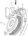
- FIG. 3 shows a perspective view of a vibrating system 1 a with the coil spring 2a and the oscillating or balance wheel 3a.
- the balance spring 2a and the balance wheel 3a are made of the same material and / or in the same manner as described above for the coil spring 2 and the balance wheel 3.
- the balance wheel 3a is designed spoke-like, consisting of an outer ring 4, four radially extending from the ring 4 inwardly extending spokes 5 and a central hub portion 6, which has the opening 6.1 for attachment of the balance shaft and integral with the spokes 5 and the outer ring 4 is made.
- the outer ring 4 is formed on its inside with a circumferential groove 7 and between the spokes 5 each having a fork-like attachment portion 8.
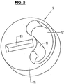
- an adjusting element 9 which is integrally formed from a non-magnetic metallic material, e.g. made of molybdenum or of a corrosion-resistant steel.
- the adjusting elements 9 consist of a circular-disk-shaped body 10 with a pin 11 which is arranged coaxially with the axis of this body and projecting beyond an end face of the centering element 9 with a circular-cylindrical outer surface. Furthermore, in the body 10 is a continuous, ie at both ends of the Disc-shaped body 10 is provided with an open and arcuately curved recess 12 which extends over an angular range of slightly less than 180 ° about the axis of the centering 9, in such a way that the centering element 9 and its body 10 has a continuous edge at its periphery , the center of gravity of the centering element 9 but offset radially to the axis of the centering element 9.
- each centering element is rotatably provided on a mounting portion 8 about an axis parallel to the axis of the balance wheel 3a, with a certain stiffness in that the respective pin 11 is held by snapping or latching on the fork-like mounting portion 8 and each adjusting element 9 extends on the periphery with its disc-like body 10 in the groove 7, where it is axially secured and bears radially against the bottom of the groove 7.
- each adjusting element 9 is pushed with its pin 11 radially on the associated fork-like mounting portion 8.
- the center of mass of each adjusting element 9 u.a. displaced radially to the axis of the balance wheel 3a and thereby set the dynamic moment of inertia in the desired manner.
- the balance spring 2a is fastened with the inner end in a suitable manner to the balance shaft, not shown.
- the outer end of the coil spring 2a is held on a spring holder block or block 14 of a spring holder 15 which is adjustable by pivoting about the axis of the balance wheel 3a.
- FIG. 6 is made of metallic material spring holder block 14 with a portion 14.1, with which it can be fixed in an opening 16 of the spring holder 15 by clipping or latching, and with a section 14.2 with two fork or clamp arms 17 and 18 executed which form between them a clamping gap 19 in which the coil spring 2a are secured by clamping can.
- the clamping gap 19 is open to the underside facing away from the section 14.1 and also to two opposite end faces of the spring holder block 14 and is bounded by a surface 20 on the side facing the section 14.1.
- the spring holder block 14 In the assembled state of the spring holder block 14 is oriented with its longitudinal extent parallel to the axis of the balance wheel 3a.
- the outer portion of the coil spring 2a is inserted into the clamping gap 19 from the underside of the spring holder block 14 facing away from the section 14.1 or the spring holder 15.
- the coil spring 2a is already held on the spring holder 15 mounted on the spring block 14 such that even a change and adjustment of the effective spring length, which is required for the frequency of the mechanical vibration system 1, by moving the coil spring 2a relative to the spring holder block 14 while maintaining the Clamping connection is possible.
- the connection between the coil spring 2a and the spring holder block 14 is fixed, again using a suitable adhesive or fixing varnish.
- the adjusting elements 9, but in particular the respective spring holder block 14, are preferably manufactured as so-called LIGA parts with the LIGA method known to those skilled in the art, which enables the production of metallic moldings with very small dimensions by the method steps lithography, electroplating and impression molding.
- FIG. 7 schematically the formation of a bearing and / or sliding and / or mounting surface of a functional element 21 reproduced, which consists of silicon, preferably of polycrystalline, for example, epitaxially deposited polycrystalline silicon.
- the bearing and / or sliding and / or mounting surface forming surface 22 of the functional element 21 is formed by a multilayer coating, at least consisting of a directly adjoining the silicon material of the functional element 21 coating 23 of silicon oxide, for example by thermal Oxidation or produced in any other suitable manner.
- the coating 23 is followed by a metallic intermediate layer 24, which preferably consists of titanium nitride and / or titanium carbide and / or tungsten carbide and is applied, for example, in a PVD coating process.
- the intermediate layer 24 may in turn be designed in a multi-layered manner, specifically in several individual layers, for example from the aforementioned materials.
- the intermediate layer 24 is followed by a coating 25 forming the actual outer surface, which is embodied as a DLC coating and produced, for example, by CVD deposition.
- the invention is based on the finding that improved adhesion of the layer 25 to the layer 23 is achieved by the metallic intermediate layer 24, so that the layer 25 is effectively prevented from flaking or loosening by the functional element 21 during assembly and during use of a clock , This is true not only for storage and sliding surfaces, but in particular for mounting surfaces and especially for those with or on which a clamping attachment, for example, a clamping attachment of the spiral or balance spring 2 or the oscillating body to a shaft, etc.
Landscapes
- Engineering & Computer Science (AREA)
- Manufacturing & Machinery (AREA)
- Physics & Mathematics (AREA)
- General Physics & Mathematics (AREA)
- Springs (AREA)
- Micromachines (AREA)
Abstract
Es ist ein mechanisches Schwingsystem (1) für Uhren, insbesondere Armbanduhren und ein Verfahren zum Herstellen eines Schwingsystems (1) offenbart. Das Schwingsystem (1) besitzt eine Unruhfeder (2, 2a) und ein Unruhrad (3, 3a) mit einer Welle zur Befestigung der Unruhfeder (2, 2a). Die Unruhfeder (2, 2a) besteht aus einem Silizium-Werkstoff, mit einer Korngröße im Bereich zwischen 10 nm und 50000 nm. Ein Windungsquerschnitt der Unruhfeder (2, 2a) beträgt 0,001 mm 2 bis 0,3 mm 2 .It is a mechanical vibration system (1) for watches, in particular wristwatches and a method for producing a vibration system (1) disclosed. The oscillating system (1) has a balance spring (2, 2a) and a balance wheel (3, 3a) with a shaft for attachment of the balance spring (2, 2a). The balance spring (2, 2a) consists of a silicon material, with a grain size in the range between 10 nm and 50,000 nm. A winding cross section of the balance spring (2, 2a) is 0.001 mm 2 to 0.3 mm 2.
Description
Die Erfindung bezieht sich auf ein mechanisches Schwingsystem für Uhren gemäß Patentanspruch 1 sowie ein Verfahren zum Herstellen eines mechanischen Schwingsystems für UhrenThe invention relates to a mechanical vibration system for watches according to claim 1 and a method for producing a mechanical vibration system for watches
Es wurde bereits vorgeschlagen, die Feder oder Unruhfeder (Spiralfeder) eines mechanischen Schwingsystems aus Silizium zu fertigen und, u.a. zur Verbesserung der mechanischen Festigkeit und zur Temperaturkompensation an deren Oberflächen, mit einer Schicht aus Siliziumoxid zu versehen. Insbesondere dann, wenn die Schicht aus Siliziumoxid thermisch erfolgt ist, besteht bei Schichtdicken, die für eine optimale
Temperaturkompensation erforderlich wären, d.h. bei Schichtdicken größer als 4 µm u.a., die Gefahr einer Verformung, zumindest einer partiellen Verformung der Unruhfeder, was dann zu einer Beeinträchtigung der Ganggenauigkeit des Schwingsystems und/oder zu nicht reproduzierbaren Verhältnissen bei der Fertigung führt.It has already been proposed to manufacture the spring or balance spring (spiral spring) of a mechanical vibration system made of silicon and, inter alia, to improve the mechanical strength and for temperature compensation on their surfaces, to provide a layer of silicon oxide. In particular, when the layer of silicon oxide is thermally, there is at layer thicknesses that are optimal
Temperature compensation would be required, ie at layer thicknesses greater than 4 microns, inter alia, the risk of deformation, at least a partial deformation of the balance spring, which then leads to an impairment of the accuracy of the vibration system and / or not reproducible conditions in the production.
Die europäische Patentanmeldung
Die deutsche Übersetzung der europäischen Patentschrift
Die internationale Patentanmeldung
Aufgabe der Erfindung ist es, ein Schwingsystem aufzuzeigen, welches diese Nachteile vermeidet. Zur Lösung dieser Aufgabe ist ein mechanisches Schwingsystem entsprechend dem Patentanspruch 1 ausgebildet.The object of the invention is to show a vibration system which avoids these disadvantages. To solve this problem, a mechanical vibration system according to claim 1 is formed.
Eine weitere Aufgabe der Erfindung ist es, ein Verfahren zum Herstellen eines mechanischen Schwingsystems für Uhren aufzuzeigen, welches diese Nachteile vermeidet. Zur Lösung dieser Aufgabe ist ein Verfahren zum Herstellen eines mechanischen Schwingsystems für Uhren entsprechend dem Patentanspruch 8 ausgebildet.A further object of the invention is to provide a method for producing a mechanical vibration system for watches, which avoids these disadvantages. To solve this problem, a method for producing a mechanical vibration system for watches according to
Funktionselemente im Sinne der Erfindung sind insbesondere solche eines mechanischen Schwingsystems für Uhren und dabei speziell für mechanische Uhren oder Armbanduhren, nämlich insbesondere die Spiral- und Unruhfeder, der Schwingkörper bzw. das Unruhrad, die Welle des Schwingkörpers, Elemente zur Befestigung der Unruhfeder am Schwingkörper bzw. Elemente zur Befestigung der Unruhfeder an der Welle des Schwingkörpers sowie an einer Platine des Uhrwerks, die sogenannte Doppelscheibe an der Welle des Schwingkörpers zum Auslenken des Ankers, der Anker sowie das Ankerrad. Funktionselemente im Sinne der Erfindung sind weiterhin auch Zahnräder eines Uhrwerks generell.Functional elements in the context of the invention are in particular those of a mechanical oscillating system for watches and in particular for mechanical watches or wristwatches, namely in particular the spiral and balance spring, the oscillating body or the balance wheel, the shaft of the oscillating body, elements for fixing the balance spring on the oscillating body or Elements for attachment of the balance spring on the shaft of the oscillating body and on a circuit board of the movement, the so-called double disc on the shaft of the oscillating body for deflecting the armature, the armature and the escape wheel. Functional elements in the context of the invention are also gears of a movement generally.
Nach einem Aspekt der Erfindung besteht das mechanische Schwingsystem für Uhren, insbesondere für Armbanduhren, aus einer Unruhfeder und einem Unruhrad mit einer Welle zur Befestigung der Unruhfeder. Die Unruhfeder besteht aus einem Silizium-Werkstoff (insbesondere polykristallines Silizium), mit einer Korngröße im Bereich zwischen 10 nm und 50000 nm. Ein Windungsquerschnitt der Unruhfeder beträgt 0,001 mm2 bis 0,3 mm2.According to one aspect of the invention, the mechanical vibration system for watches, especially for watches, from a balance spring and a balance wheel with a shaft for attachment of the balance spring. The balance spring consists of a silicon material (in particular polycrystalline silicon), with a particle size in the range between 10 nm and 50000 nm. A winding cross section of the balance spring is 0.001 mm 2 to 0.3 mm 2 .
Gemäß einem Aspekt der Erfindung liegt die Korngröße bevorzugt im Bereich zwischen 10 nm und 10000 nm. Der Silizium-Werkstoff kann ein epitaktisch abgeschiedenes polykristallines Silizium sein. Der Längenausdehnungskoeffizient der Unruhfeder ist kleiner als 8x10⁻⁶/K.According to one aspect of the invention, the grain size is preferably in the range between 10 nm and 10000 nm. The silicon material may be an epitaxially deposited polycrystalline silicon. The coefficient of linear expansion of the balance spring is less than 8x10 -6 / K.
Gemäß einer bevorzugten Ausführungsform der Erfindung ist die Unruhfeder an der Außenfläche ihrer Windungen mit einer thermisch erzeugten Schicht aus Siliziumoxid versehen. Diese Schicht besitzt eine Dicke von maximal 4 µm, bevorzugt von maximal 3µm oder kleiner.According to a preferred embodiment of the invention, the balance spring is provided on the outer surface of its windings with a thermally generated layer of silicon oxide. This layer has a maximum thickness of 4 microns, preferably of a maximum of 3 microns or smaller.
Das Verfahren zum Herstellen eines mechanischen Schwingsystems für Uhren umfasst die folgenden Schritte:
- dass für eine Unruhfeder ein Wafer erzeugt wird, wobei ein Silizium-Werkstoff eine Korngröße im Bereich zwischen 10 nm und 50000 nm besitzt;
- dass die Unruhfeder mehrere Windungen besitzt, die mit einem Windungsquerschnitt von 0,001 mm2 bis 0,3 mm2 aus dem Wafer hergestellt werden;
- dass Außenflächen der Windungen der Unruhfeder mit einer thermisch erzeugten Schicht aus Silizumoxid versehen werden; und
- dass die Unruhfeder auf einer Welle eines Unruhrads des Schwingsystems befestigt wird.
- that a wafer is produced for a balance spring, wherein a silicon material has a particle size in the range between 10 nm and 50,000 nm;
- that the balance spring has a plurality of turns, which are produced with a winding cross-section of 0.001 mm 2 to 0.3 mm 2 from the wafer;
- that outer surfaces of the turns of the balance spring are provided with a thermally generated layer of Silizumoxid; and
- that the balance spring is mounted on a shaft of a balance wheel of the vibration system.
Der Silizium-Werkstoff ist z.B. ein polykristallines Silizium, das epitaktisch abgeschieden und aus welchem der Wafer gebildet wird.The silicon material is e.g. a polycrystalline silicon which is epitaxially deposited and from which the wafer is formed.
Die Windungen der Unruhfeder werden durch Schneiden und/oder Ätzen mittels einer Maskierungs-und Ätztechnik aus dem Wafer gebildet.The turns of the balance spring are formed by cutting and / or etching from the wafer by means of a masking and etching technique.
Mit einem innenliegenden Ende wird die Unruhfeder in geeigneter Weise an der Welle befestigt und ein außenliegendes Ende der Unruhfeder wird mit einem Federhalterklotz an einem durch Schwenken um eine Achse des Unruhrades einstellbaren Federhalter gehalten.With an inboard end, the balance spring is suitably secured to the shaft, and an outboard end of the balance spring is held by a spring retainer block on a spring retainer adjustable by pivoting about an axis of the balance wheel.
Der Erfindung liegt u.a. die Erkenntnis zugrunde, dass eine hohe Ganggenauigkeit, insbesondere auch eine temperaturunabhängige Ganggenauigkeit in besonders einfacher Weise bei einem mechanischen Schwingsystem mit einer Unruhfeder aus einem nicht metallischen kristallinen Werkstoff mit einer Korngröße im Bereich zwischen 10 nm und 50 000 nm und mit einem thermischen Längenausdehnungskoeffizienten kleiner 8 10"7K und/oder aus Silizium durch Verwendung von Molybdän (Mo) für den Schwingkörper bzw. das Unruhrad erreichbar ist, und zwar insbesondere auch bei stark reduzierter Dicke einer Siliziumoxid-Beschichtung der Unruhfeder.The invention is based inter alia on the finding that a high accuracy, in particular a temperature-independent accuracy in a particularly simple manner in a mechanical vibration system with a balance spring of a non-metallic crystalline material having a particle size in the range between 10 nm and 50 000 nm and with a thermal expansion coefficient smaller 8 10 "7K and / or silicon by using molybdenum (Mo) for the vibrating body and the balance wheel is accessible, and in particular even at greatly reduced thickness of a silicon oxide coating of the balance spring.
Nach einem Aspekt der Erfindung sind bei dem mechanischen Schwingsystem für Uhren, insbesondere Armbanduhren, mit einer Unruhfeder und einem Schwingkörper die Unruhfeder aus Silizium und der Schwingkörper zur Temperaturkompensation aus Molybdän oder einer Molybdän in einem hohen Anteil enthaltenden Legierung gefertigt,
wobei dieses Schwingsystem in Weiterbildung der Erfindung beispielsweise so ausgeführt ist,
- dass die Unruhfeder an deren Oberflächen mit einer Schicht aus Siliziumoxid versehen ist,
- und/oder
- dass die Schicht aus Siliziumoxid eine Schichtdicke von maximal 4µm, vorzugsweise von maximal 3 µm, aufweist,
- und/oder
- dass der Schwingkörper ein rad- oder scheibenartiger Schwingkörper ist,
- und/oder
- dass die Unruhfeder aus polykristallinem Silizium hergestellt ist,
- und/oder
- dass an einem radial außenliegenden Bereich des Schwingkörpers oder eines diesen Schwingkörper bildenden Unruhrades Justierelemente zur Einstellung des dynamischen Trägheitsmomentes des Schwingkörpers in Bezug auf seine Schwingachse vorgesehen sind,
- und/oder
- dass die Zentrierelemente jeweils von wenigstens einem um eine Achse parallel oder im Wesentlichen parallel zur Schwingachse dreh- oder schwenkbar am Massenkörper mit einem gegenüber der Dreh- oder Schwenkachse versetzten Massenschwerpunkt aufweisen,
- und/oder
- dass die Justierelemente durch Klipsen oder Verrasten am Schwingkörper bzw. an der Innenseite des Unruhrades oder eines Ringes des Unruhrades gehalten sind, und/oder
- dass ein Federhalterklotz mit einem Klemmschlitz zum klemmenden Halten der Spiral- oder Unruhfeder im Bereich ihres außenliegenden Federendes vorgesehen ist,
wherein this vibration system is embodied in a development of the invention, for example, as
- that the balance spring is provided on its surfaces with a layer of silicon oxide,
- and or
- the layer of silicon oxide has a layer thickness of not more than 4 μm, preferably of not more than 3 μm,
- and or
- that the vibrating body is a wheel or disk-like vibrating body,
- and or
- that the balance spring is made of polycrystalline silicon,
- and or
- in that adjusting elements for adjusting the dynamic moment of inertia of the oscillating body with respect to its oscillating axis are provided on a radially outer region of the oscillating body or of a balance wheel forming this oscillating body,
- and or
- in that the centering elements each have at least one about an axis parallel or substantially parallel to the swing axis rotatable or pivotable on the mass body with a relative to the rotational or pivot axis offset center of gravity,
- and or
- that the adjusting elements are held by clipping or latching on the oscillating body or on the inside of the balance wheel or a ring of the balance wheel, and / or
- a spring holder block is provided with a clamping slot for clamping the spiral spring or balance spring in the region of its outer spring end,
In Weiterbildung der Erfindung sind der Schwingkörper oder das Unruhrad beispielsweise so ausgebildet, dass die Justierelemente durch Klipsen oder Verrasten am Schwingkörper bzw. an der Innenseite des Unruhrades oder eines Ringes des Unruhrades gehalten sind, und/oder dass der Schwingkörper aus Molybdän oder einer Molybdän in einem hohen Anteil enthaltenden Legierung gefertigt ist, wobei die vorgenannten Merkmale jeweils einzeln oder in beliebiger Kombination verwendet sein können.In a further development of the invention, the oscillating body or balance wheel, for example, designed so that the adjusting elements are held by clipping or latching on the oscillating body or on the inside of the balance wheel or a ring of the balance wheel, and / or that the oscillating body of molybdenum or a molybdenum in made of a high proportion alloy, wherein the aforementioned features may be used individually or in any combination.
Nach einem weiteren Aspekt der Erfindung ist bei einer Spiralfeder für ein mechanisches Schwingsystem für Uhren der Spiralfederkörper im Bereich seines außenliegenden Endes mit einem mehrfach wellenförmig ausgeführten Abschnitt versehen, wobei die Spiralfeder (Unruhfeder) in Weiterbildung der Erfindung beispielsweise so ausgeführt ist, dass sie aus Silizium besteht, und/oder, dass sie aus polykristallinem Silizium oder einer Siliziumkeramik, z.B. aus Silizium- Nitrid, hergestellt ist,
wobei die vorgenannten Merkmale der Spiralfeder jeweils einzeln oder in beliebiger Kombination verwendet sein können.According to a further aspect of the invention, in a coil spring for a mechanical oscillating system for watches, the coil spring body is provided in the region of its outer end with a multi-wave section, wherein the coil spring (balance spring) is executed in a further development of the invention, for example, that of silicon and / or that it is made of polycrystalline silicon or a silicon ceramic, eg of silicon nitride,
wherein the aforementioned features of the coil spring may be used individually or in any combination.
Nach einem weiteren Aspekt der Erfindung sind der Schwingkörper oder das Unruhrad für ein mechanisches Schwingsystem für Uhren, insbesondere Armbanduhren, mit an einem radial außenliegenden Bereich des Schwingkörpers angebrachten Justierelementen zur Einstellung des dynamischen Schwingkörper Trägheitsmomentes des Schwingkörpers in Bezug auf seine Schwingachse, so ausgeführt, wobei der Schwingkörper in Weiterbildung der Erfindung beispielsweise so ausgeführt ist,
- dass die Zentrierelemente jeweils von wenigstens einem um eine Achse parallel oder im Wesentlichen parallel zur Schwingachse dreh- oder schwenkbar am Massenkörper mit einem gegenüber der Dreh- oder Schwenkachse versetzten Massenschwerpunkt aufweisen,
- und/oder
- dass er speichenradartig ausgebildet ist,
- und/oder
- dass die Justierelemente durch Klipsen oder Verrasten am Schwingkörper bzw. an der Innenseite des Unruhrades oder eines Ringes des Unruhrades gehalten sind, und/oder
- dass er aus Molybdän oder einer Molybdän in einem hohen Anteil enthaltenden Legierung gefertigt ist,
- in that the centering elements each have at least one about an axis parallel or substantially parallel to the swing axis rotatable or pivotable on the mass body with a relative to the rotational or pivot axis offset center of gravity,
- and or
- that it is formed Speichenradartig,
- and or
- that the adjusting elements are held by clipping or latching on the oscillating body or on the inside of the balance wheel or a ring of the balance wheel, and / or
- that it is made of molybdenum or an alloy containing molybdenum in a high proportion,
Nach einem weiteren Aspekt der Erfindung ist ein Funktionselement für Uhren, insbesondere mechanische Uhren oder Armbanduhren, geschaffen, wobei das Funktionselement in Weiterbildung der Erfindung beispielsweise so ausgeführt ist,
- dass es aus einem nicht metallischen Werkstoff gefertigt ist, der ein kristalliner Werkstoff mit einer Korngröße im Bereich zwischen 10 nm und 50 000 nm und/oder mit einem thermischen Längenausdehnungskoeffizienten kleiner 8 10"7K I ist,
- und/oder
- dass bei Ausbildung als Spiralfeder der Windungsquerschnitt 0,001 mm2 bis 0,01 mm2 oder 0,001 mm2 bis 0,03 mm2 oder 0,001 mm2 bis 0,3 mm2 beträgt,
- und/oder
- dass es wenigstens eine Lager- und/oder Gleit- und/oder Montagefläche bildet, an der die Oberfläche des Funktionselementes aus einer inneren Schicht aus Siliziumoxid und einer die Außenfläche bildenden DLC-Beschichtung besteht,
- und/oder
- dass zwischen der von der DLC-Beschichtung gebildeten äußeren Schicht und der inneren Schicht aus Siliziumoxid wenigstens eine metallische Zwischenschicht vorgesehen ist,
- und/oder
- dass die Zwischenschicht ein- oder mehrlagig ausgeführt ist,
- und/oder dass die Zwischenschicht bzw. die wenigstens eine Lage dieser Zwischenschicht aus Titan-Nitrid und/oder Titan-Carbid und/oder Wolfram-Carbid besteht,
- und/oder
- dass es als Spiral- oder Unruhfeder, als Schwingkörper, als Welle, insbesondere Unruh-Welle, als Anker, als Ankerrad, als Doppelscheibe an der Unruhwelle oder als Zahnrad ausgebildet ist,
- that it is made of a non-metallic material which is a crystalline material having a particle size in the range between 10 nm and 50,000 nm and / or with a coefficient of thermal expansion of less than 8 × 10 -7 K I,
- and or
- that, when designed as a helical spring, the winding cross-section is 0.001 mm 2 to 0.01 mm 2 or 0.001 mm 2 to 0.03 mm 2 or 0.001 mm 2 to 0.3 mm 2 ,
- and or
- that it forms at least one bearing and / or sliding and / or mounting surface on which the surface of the functional element consists of an inner layer of silicon oxide and a DLC coating forming the outer surface,
- and or
- at least one metallic intermediate layer is provided between the outer layer formed by the DLC coating and the inner layer made of silicon oxide,
- and or
- that the intermediate layer is made in one or more layers,
- and / or that the intermediate layer or the at least one layer of this intermediate layer consists of titanium nitride and / or titanium carbide and / or tungsten carbide,
- and or
- that it is designed as a spiral or balance spring, as a vibrating body, as a wave, in particular balance shaft, as an anchor, as an escape wheel, as a double disc on the balance wheel or as a gear,
Weiterbildungen, Vorteile und Anwendungsmöglichkeiten der Erfindung ergeben sich auch aus der nachfolgenden Beschreibung von Ausführungsbeispielen und aus den Figuren. Dabei sind alle beschriebenen und/oder bildlich dargestellten Merkmale für sich oder in beliebiger Kombination grundsätzlich Gegenstand der Erfindung, unabhängig von ihrer Zusammenfassung in den Ansprüchen oder deren Rückbeziehung. Auch wird der Inhalt der Ansprüche zu einem Bestandteil der Beschreibung gemacht.Further developments, advantages and applications of the invention will become apparent from the following description of exemplary embodiments and from the figures. In this case, all described and / or illustrated features alone or in any combination are fundamentally the subject of the invention, regardless of their summary in the claims or their dependency. Also, the content of the claims is made an integral part of the description.
Die Erfindung wird im Folgenden anhand der Figuren an Ausführungsbeispielen näher erläutert. Es zeigen:
- Fig. 1
- in vereinfachter Funktionsdarstellung die wesentlichen Elemente eines mechanischen Schwingsystems einer Armbanduhr;
- Fig. 2
- in Draufsicht die Spiralfeder des Schwingsystems der
Figur 1 ; - Fig. 3
- in perspektivischer Teildarstellung ein mechanisches Schwingsystem für Uhren, insbesondere Armbanduhren, gemäß einer weiteren Ausführungsform;
- Fig. 4
- in Einzeldarstellung und in Draufsicht das Schwing- und Unruhrad des Schwingsystems der
Figur 3 ; - Fig. 5
- in perspektivischer Darstellung und in Draufsicht eines der Zentrierelemente des Unruhrades des Schwingsystems der
Figur 3 ; - Fig. 6
- in Einzeldarstellung einen Federhalter oder Halteklotz für die Spiral- oder Unruhfeder des Schwingsystems der
Figur 3 ; - Fig. 7
- in vereinfachter Darstellung einen Schnitt durch eine mehrlagige Beschichtung auf einem aus Silizium hergestellten Funktionselement.
- Fig. 1
- in a simplified functional representation of the essential elements of a mechanical vibration system of a wristwatch;
- Fig. 2
- in plan view, the coil spring of the vibration system of
FIG. 1 ; - Fig. 3
- in a perspective partial representation of a mechanical vibration system for watches, in particular wristwatches, according to a further embodiment;
- Fig. 4
- in individual representation and in plan view of the oscillating and balance wheel of the vibration system of
FIG. 3 ; - Fig. 5
- in a perspective view and in plan view of one of the centering of the balance wheel of the oscillating system of
FIG. 3 ; - Fig. 6
- in an individual representation of a spring holder or retaining block for the spiral or balance spring of the vibration system of
FIG. 3 ; - Fig. 7
- in a simplified representation of a section through a multilayer coating on a functional element made of silicon.
Das in der
Die Unruhfeder 2 ist an der Außenfläche ihrer Windungen mit einer z.B. thermisch erzeugten Schicht aus Siliziumoxid versehen. Diese Schicht besitzt eine Dicke von maximal 4µm, bevorzugt von maximal 3µm oder kleiner.The
Die Schwingmasse bzw. der Schwingkörper, d.h. das Schwing- oder Unruhrad 3, welches beispielsweise die für derartige Räder übliche speichenradartige Form aufweist, ist aus Molybdän oder aus einer Legierung mit einem hohen Molybdän-Anteil gefertigt. Durch die Kombination von Silizium (für die Unruhfeder 2) und Molybdän (für das Unruhrad 3) wird ein in optimaler Weise temperaturkompensiertes mechanisches Schwingsystem erhalten, d.h. ein mechanisches Schwingsystem, dessen Gang- oder Frequenzgenauigkeit insbesondere auch unabhängig von Temperaturänderungen ist.The oscillating mass or oscillating body, i. the oscillating or
Die
Die Spiralfeder 2 mit dem Abschnitt 2.1 ist in vorteilhafter Weise auch für Schwingsysteme von Uhren, insbesondere Armbanduhren, verwendbar, bei denen die Schwingmasse anders als vorstehend beschrieben ausgeführt ist.The
Die
Das Unruhrad 3a ist speichenradartig ausgeführt, und zwar bestehend aus einem äußeren Ring 4, aus vier vom Ring 4 radial nach innen verlaufenden Speichen 5 und aus einem mittleren Nabenabschnitt 6, der die Öffnung 6.1 zur Befestigung der Unruh-Welle aufweist und einstückig mit den Speichen 5 und dem äußeren Ring 4 hergestellt ist.The
Der äußere Ring 4 ist an seiner Innenseite mit einer umlaufenden Nut 7 sowie zwischen den Speichen 5 jeweils mit einem gabelartigen Befestigungsabschnitt 8 ausgebildet. An jedem Befestigungsabschnitt 8 ist ein Justierelement 9 vorgesehen, welches einstückig aus einem nicht magnetischen metallischen Material, z.B. aus Molybdän oder aus einem korrosionsbeständigen Stahl, gefertigt ist. Mit den Justierelementen 9, die ebenso wie die Speichen 5 in gleichmäßigen Winkelabständen um die Achse des Unruhrades 3a bzw. der Öffnung 6.1 verteilt angeordnet sind, kann das für die Frequenz bzw. Schwingungsdauer des Schwingsystems maßgebliche dynamische Trägheitsmoment des Unruhrades 3a eingestellt werden. Die Befestigungsabschnitte 8 sind jeweils unterhalb der Nut 7 vorgesehen.The
Die Justierelemente 9 bestehen hierfür aus einem kreisscheibenförmigen Körper 10 mit einem achsgleich mit der Achse dieses Körpers angeordneten und über eine Stirnseite des Zentrierelementes 9 wegstehenden Zapfen 11 mit kreiszylinderförmiger Außenfläche. Weiterhin ist im Körper 10 eine durchgehende, d.h. an beiden Stirnseiten des scheibenförmigen Körpers 10 offene und bogenförmig gekrümmte Ausnehmung 12 vorgesehen, die sich über einen Winkelbereich von etwas weniger als 180° um die Achse des Zentrierelementes 9 erstreckt, und zwar derart, dass das Zentrierelement 9 bzw. dessen Körper 10 an seinem Umfang einen durchgehenden Rand aufweist, der Massenschwerpunkt des Zentrierelementes 9 aber radial zur Achse des Zentrierelementes 9 versetzt ist. An der dem Zapfen 11 abgewandten Oberseite ist der Körper 10 weiterhin mit einer schlitzförmigen, sich radial oder in etwa radial zur Achse des Zentrierelementes erstreckenden Vertiefung 13 versehen, die die Angriffs oder Betätigungsfläche für ein Einstell-Werkstück, beispielsweise für einen Schraubenzieher, bildet. Mit dem Zapfen 11 ist jedes Zentrierelement an einem Befestigungsabschnitt 8 um eine Achse parallel zur Achse des Unruhrades 3a drehbar vorgesehen, und zwar mit einer gewissen Schwergängigkeit dadurch, dass der jeweilige Zapfen 11 durch Einschnappen oder Verrasten an dem gabelartigen Befestigungsabschnitt 8 gehalten ist und jedes Justierelement 9 am Umfang mit seinem scheibenartigen Körper 10 in die Nut 7 hineinreicht, dort axial gesichert ist und radial gegen den Boden der Nut 7 anliegt.For this purpose, the adjusting
Die Montage der Justierelemente 9 am Ring 4 erfolgt also derart, dass jedes Justierelement 9 mit seinem Zapfen 11 radial auf den zugehörigen gabelartigen Befestigungsabschnitt 8 aufgeschoben wird. Durch Drehen oder Schwenken der Justierelemente 9 um die Achse ihrer Zapfen 11 können der Masseschwerpunkt jedes Justierelementes 9 u.a. radial zur Achse des Unruhrades 3a verlagert und dadurch das dynamische Massenträgheitsmoment in der gewünschten Weise eingestellt werden. Nach der Einstellung der Justierelemente 9 werden diese durch einen geeigneten Kleber oder Fixierlack fixiert.The assembly of the adjusting
Die Unruhfeder 2a ist mit dem innenliegenden Ende in geeigneter Weise an der nicht dargestellten Unruhwelle befestigt. Das außenliegende Ende der Spiralfeder 2a ist an einem Federhalterklötzchen oder -klotz 14 eines durch Schwenken um die Achse des Unruhrades 3a einstellbaren Federhalters 15 gehalten.The balance spring 2a is fastened with the inner end in a suitable manner to the balance shaft, not shown. The outer end of the coil spring 2a is held on a spring holder block or block 14 of a
Wie insbesondere der
Im montiertem Zustand ist der Federhalterklotz 14 mit seiner Längserstreckung parallel zur Achse des Unruhrades 3a orientiert. Bei der Montage des Schwingsystems 1 wird der außenliegende Abschnitt der Spiralfeder 2a von der dem Abschnitt 14.1 bzw. dem Federhalter 15 abgewandten Unterseite des Federhalterklotzes 14 her in den Klemmspalt 19 eingeführt. Damit ist die Spiralfeder 2a bereits an dem am Federhalter 15 montierten Federhalterklotz 14 derart gehalten, dass noch eine Änderung und Einstellung der wirksamen Federlänge, die für die Frequenz des mechanischen Schwingungssystems 1 erforderlich ist, durch Verschieben der Spiralfeder 2a relativ zum Federhalterklotz 14 bei Aufrechterhaltung der Klemmverbindung möglich ist. Nach dieser Einstellung wird die Verbindung zwischen der Spiralfeder 2a und dem Federhalterklotz 14 fixiert, und zwar wiederum unter Verwendung eines geeigneten Klebers oder Fixierlacks.In the assembled state of the
Die Justierelemente 9, insbesondere aber der jeweilige Federhalterklotz 14, sind bevorzugt als sogenannte LIGA-Teile mit dem dem Fachmann bekannten LIGA-Verfahren gefertigt, welches durch die Verfahrensschritte Lithographie, Galvanik und Abformung die Herstellung von metallischen Formkörpern mit sehr kleinen Abmessungen ermöglicht.The adjusting
In der
Die Erfindung wurde voranstehend an Ausführungsbeispielen beschrieben. Es versteht sich, dass zahlreiche Änderungen sowie Abwandlungen möglich sind, ohne dass dadurch der der Erfindung zugrundeliegende Erfindungsgedanke verlassen wird. Anstelle des vorgenannten Silizium-Materials (z.B. polykristallinem Silizium) eignet sich insbesondere auch ein Sintermaterial auf Silizium-Basis bzw. Silizium-Sintermaterial und/oder der nicht metallische kristalline oder gesinterte Werkstoff mit der Korngröße im Bereich zwischen 10 nm und 50 000 nm und mit dem thermischen Längenausdehnungskoeffizienten kleiner 8 x 10⁻⁶/K.The invention has been described above by means of exemplary embodiments. It is understood that numerous changes and modifications are possible without thereby departing from the inventive concept underlying the invention. Instead of the aforementioned silicon material (eg polycrystalline silicon), a sintered material based on silicon or silicon sintered material and / or the non-metallic crystalline or sintered material with a particle size in the range between 10 nm and 50,000 nm and with the thermal coefficient of linear expansion is less than 8 x 10 -6 / K.
- 1 , 1a1, 1a
- mechanisches Schwingsystemmechanical vibration system
- 2, 2a2, 2a
- Unruhfederbalance spring
- 3, 3a3, 3a
- Unruhradbalance wheel
- 44
- Reifen oder RingTire or ring
- 55
- Speichespoke
- 66
- nabenartiger Abschnitthub-like section
- 77
- Nutgroove
- 88th
- Befestigungsabschnittattachment section
- 99
- Justierelementadjusting
- 1010
-
scheibenförmiger Körper des Justierelementes 9disc-shaped body of the adjusting
element 9 - 1 11 1
-
Zapfen des Justierelementes 9Spigot of the adjusting
element 9 - 1212
- Ausnehmungrecess
- 1 31 3
- Schlitzslot
- 1414
- FederhalterklötzchenSpring mounting block
- 14.1 , 14.214.1, 14.2
- Abschnitt des FederhalterklötzchensSection of the spring holder block
- 1515
- Federhalterpenholder
- 1616
- Öffnungopening
- 17, 1817, 18
- Klemmarmclamping arm
- 1919
- Klemmspaltnip
- 2020
- Anlageflächecontact surface
- 2121
- Funktionselementfunctional element
- 2222
-
Oberfläche des Funktionselementes 21Surface of the
functional element 21 - 23, 24, 2523, 24, 25
- Beschichtung oder LageCoating or layer
Claims (15)
die Unruhfeder (2, 2a) aus einem Silizium-Werkstoff besteht, mit einer Korngröße im Bereich zwischen 10 nm und 50000 nm und ein Windungsquerschnitt der Unruhfeder (2, 2a) 0,001 mm2 bis 0,3 mm2 beträgt.Mechanical oscillating system (1) for watches, in particular wristwatches, with a balance spring (2, 2a) and a balance wheel (3, 3a) with a shaft for fixing the balance spring (2, 2a), wherein
the balance spring (2, 2a) consists of a silicon material having a particle size in the range between 10 nm and 50,000 nm and a winding cross-section of the balance spring (2, 2a) is 0.001 mm 2 to 0.3 mm 2 .
Applications Claiming Priority (11)
| Application Number | Priority Date | Filing Date | Title |
|---|---|---|---|
| DE102009007973 | 2009-02-06 | ||
| DE102009013741 | 2009-03-20 | ||
| DE102009025645 | 2009-06-17 | ||
| DE102009030539 | 2009-06-24 | ||
| DE102009031841A DE102009031841A1 (en) | 2009-02-06 | 2009-07-03 | Mechanical oscillating system for watch i.e. wrist watch, has balance spring made of non-metallic crystalline or sintered material, and oscillating body for temperature compensation and made of molybdenum |
| DE102009050045 | 2009-09-24 | ||
| DE102009048580 | 2009-10-07 | ||
| DE102009060024 | 2009-12-21 | ||
| DE102010004025 | 2010-01-04 | ||
| DE102010005257 | 2010-01-20 | ||
| EP10721923.0A EP2394202B1 (en) | 2009-02-06 | 2010-02-04 | Mechanical oscillating system for watches and functional element for watches |
Related Parent Applications (2)
| Application Number | Title | Priority Date | Filing Date |
|---|---|---|---|
| EP10721923.0A Division-Into EP2394202B1 (en) | 2009-02-06 | 2010-02-04 | Mechanical oscillating system for watches and functional element for watches |
| EP10721923.0A Division EP2394202B1 (en) | 2009-02-06 | 2010-02-04 | Mechanical oscillating system for watches and functional element for watches |
Publications (1)
| Publication Number | Publication Date |
|---|---|
| EP3101484A1 true EP3101484A1 (en) | 2016-12-07 |
Family
ID=44951556
Family Applications (2)
| Application Number | Title | Priority Date | Filing Date |
|---|---|---|---|
| EP16165465.2A Withdrawn EP3101484A1 (en) | 2009-02-06 | 2010-02-04 | Mechanical oscillation system for timepieces and method for manufacturing a mechanical oscillation system for watches |
| EP10721923.0A Revoked EP2394202B1 (en) | 2009-02-06 | 2010-02-04 | Mechanical oscillating system for watches and functional element for watches |
Family Applications After (1)
| Application Number | Title | Priority Date | Filing Date |
|---|---|---|---|
| EP10721923.0A Revoked EP2394202B1 (en) | 2009-02-06 | 2010-02-04 | Mechanical oscillating system for watches and functional element for watches |
Country Status (4)
| Country | Link |
|---|---|
| US (1) | US20110292770A1 (en) |
| EP (2) | EP3101484A1 (en) |
| DE (1) | DE202010018420U1 (en) |
| WO (1) | WO2010088891A2 (en) |
Families Citing this family (18)
| Publication number | Priority date | Publication date | Assignee | Title |
|---|---|---|---|---|
| WO2010088891A2 (en) | 2009-02-06 | 2010-08-12 | Konrad Damasko | Mechanical oscillating system for watches and functional element for watches |
| EP2437126B1 (en) * | 2010-10-04 | 2019-03-27 | Rolex Sa | Balance wheel-hairspring regulator |
| EP2474871B1 (en) * | 2011-01-06 | 2017-05-10 | ETA SA Manufacture Horlogère Suisse | Index pin for sprung balance |
| EP2511229B1 (en) * | 2011-04-12 | 2017-03-08 | GFD Gesellschaft für Diamantprodukte mbH | Micromechanical component with reinforced flanks |
| EP2520983A1 (en) * | 2011-05-03 | 2012-11-07 | Nivarox-FAR S.A. | Barrel comprising resilient energy accumulation means |
| CH704924B1 (en) * | 2011-05-13 | 2015-05-29 | Bucherer Ag | Balance for a watch and clock. |
| WO2013092172A1 (en) * | 2011-12-22 | 2013-06-27 | The Swatch Group Research And Development Ltd | Method for improving the pivotal movement of a mobile body |
| US10372083B2 (en) * | 2012-07-06 | 2019-08-06 | Rolex Sa | Method for treating a surface of a timepiece component, and timepiece component obtained from such a method |
| KR101846802B1 (en) * | 2012-11-16 | 2018-04-06 | 니바록스-파 에스.에이. | Compensating balance spring for a thermally compensated sprung balance resonator |
| EP2757424B1 (en) * | 2013-01-17 | 2018-05-16 | Omega SA | Part for clockwork |
| EP2757423B1 (en) * | 2013-01-17 | 2018-07-11 | Omega SA | Part for clockwork |
| CH707811A2 (en) | 2013-03-19 | 2014-09-30 | Nivarox Sa | piece component dismantled clockwork. |
| EP2781968A1 (en) * | 2013-03-19 | 2014-09-24 | Nivarox-FAR S.A. | Resonator that is less sensitive to climate variations |
| CH707808B1 (en) * | 2013-03-19 | 2017-05-15 | Nivarox Far Sa | Watch mechanism cassette. |
| CH708429A1 (en) | 2013-08-19 | 2015-02-27 | Manuf Et Fabrique De Montres Et Chronomètres Ulysse Nardin Le Locle S A | Spiral for a regulating member of a mechanical watch, a regulating member provided with such a hairspring, and method of making such a hairspring. |
| CN106104393A (en) * | 2014-01-29 | 2016-11-09 | 卡地亚国际股份公司 | The hairspring of the thermal compensation being made up of the pottery comprising silicon at it in forming and for the method regulating hairspring |
| EP3002635B8 (en) * | 2014-09-29 | 2019-05-22 | Richemont International SA | Method for producing a spring element for a clock movement or another precision instrument |
| EP3667433B1 (en) * | 2018-12-12 | 2023-02-01 | Nivarox-FAR S.A. | Spring and method for manufacturing same |
Citations (7)
| Publication number | Priority date | Publication date | Assignee | Title |
|---|---|---|---|---|
| EP0732635B1 (en) | 1995-03-17 | 2000-06-07 | C.S.E.M. Centre Suisse D'electronique Et De Microtechnique Sa | Process for the manufacture of a micromechanical element |
| DE10127733A1 (en) * | 2001-06-07 | 2003-02-06 | Silicium Energiesysteme E K Dr | Spring elements in form of screw or spiral springs used in semiconductor technology in production of weighing systems, pressure switches or sensors are made from mono-crystalline silicon |
| US6621137B1 (en) * | 2000-10-12 | 2003-09-16 | Intel Corporation | MEMS device integrated chip package, and method of making same |
| FR2842313A1 (en) * | 2002-07-12 | 2004-01-16 | Gideon Levingston | MECHANICAL OSCILLATOR (BALANCING SYSTEM AND SPIRAL SPRING) IN MATERIALS FOR REACHING A HIGHER LEVEL OF PRECISION, APPLIED TO A WATCHMAKING MOVEMENT OR OTHER PRECISION INSTRUMENT |
| EP1445670A1 (en) | 2003-02-06 | 2004-08-11 | ETA SA Manufacture Horlogère Suisse | Balance-spring resonator spiral and its method of fabrication |
| WO2005045532A2 (en) * | 2003-11-07 | 2005-05-19 | Seiko Epson Corporation | Timepiece and mainspring |
| WO2006123095A2 (en) | 2005-05-14 | 2006-11-23 | Gideon Levingston | Balance spring, regulated balance wheel assembly and methods of manufacture thereof |
Family Cites Families (6)
| Publication number | Priority date | Publication date | Assignee | Title |
|---|---|---|---|---|
| US2682744A (en) * | 1950-12-09 | 1954-07-06 | Chilowsky Constantin | Means for and method of accurately regulating chronometric devices |
| EP1422436B1 (en) * | 2002-11-25 | 2005-10-26 | CSEM Centre Suisse d'Electronique et de Microtechnique SA | Spiral watch spring and its method of production |
| EP1837722B1 (en) * | 2006-03-24 | 2016-02-24 | ETA SA Manufacture Horlogère Suisse | Micro-mechanical component in an insulating material and method of manufacture thereof |
| DE602006004465D1 (en) * | 2006-10-31 | 2009-02-05 | Swatch Group Man Serv Ag | Oscillating mass for recharging the power source of a portable instrument |
| DE102008029429A1 (en) | 2007-10-18 | 2009-04-23 | Konrad Damasko | Method for producing mechanical functional elements for movements as well as functional element produced by this method |
| WO2010088891A2 (en) | 2009-02-06 | 2010-08-12 | Konrad Damasko | Mechanical oscillating system for watches and functional element for watches |
-
2010
- 2010-02-04 WO PCT/DE2010/000126 patent/WO2010088891A2/en active Application Filing
- 2010-02-04 US US13/148,160 patent/US20110292770A1/en not_active Abandoned
- 2010-02-04 DE DE202010018420.7U patent/DE202010018420U1/en not_active Expired - Lifetime
- 2010-02-04 EP EP16165465.2A patent/EP3101484A1/en not_active Withdrawn
- 2010-02-04 EP EP10721923.0A patent/EP2394202B1/en not_active Revoked
Patent Citations (8)
| Publication number | Priority date | Publication date | Assignee | Title |
|---|---|---|---|---|
| EP0732635B1 (en) | 1995-03-17 | 2000-06-07 | C.S.E.M. Centre Suisse D'electronique Et De Microtechnique Sa | Process for the manufacture of a micromechanical element |
| DE69608724T2 (en) * | 1995-03-17 | 2001-02-08 | C.S.E.M. Centre Suisse D'electronique Et De Microtechnique S.A., Neuenburg/Neuchatel | Method for producing a micromechanical part |
| US6621137B1 (en) * | 2000-10-12 | 2003-09-16 | Intel Corporation | MEMS device integrated chip package, and method of making same |
| DE10127733A1 (en) * | 2001-06-07 | 2003-02-06 | Silicium Energiesysteme E K Dr | Spring elements in form of screw or spiral springs used in semiconductor technology in production of weighing systems, pressure switches or sensors are made from mono-crystalline silicon |
| FR2842313A1 (en) * | 2002-07-12 | 2004-01-16 | Gideon Levingston | MECHANICAL OSCILLATOR (BALANCING SYSTEM AND SPIRAL SPRING) IN MATERIALS FOR REACHING A HIGHER LEVEL OF PRECISION, APPLIED TO A WATCHMAKING MOVEMENT OR OTHER PRECISION INSTRUMENT |
| EP1445670A1 (en) | 2003-02-06 | 2004-08-11 | ETA SA Manufacture Horlogère Suisse | Balance-spring resonator spiral and its method of fabrication |
| WO2005045532A2 (en) * | 2003-11-07 | 2005-05-19 | Seiko Epson Corporation | Timepiece and mainspring |
| WO2006123095A2 (en) | 2005-05-14 | 2006-11-23 | Gideon Levingston | Balance spring, regulated balance wheel assembly and methods of manufacture thereof |
Non-Patent Citations (1)
| Title |
|---|
| RECH B ET AL: "Dünnschichtechnologie miet Silizium: Von amorph bis einkristallin", INTERNET CITATION, 1 January 2003 (2003-01-01), pages 1 - 32, XP003033041, Retrieved from the Internet <URL:http://www.fvee.de/fileadmin/publikationen/Workshopbaende/ws2003-1/ws2003-1_02_02.pdf> [retrieved on 20140102] * |
Also Published As
| Publication number | Publication date |
|---|---|
| WO2010088891A2 (en) | 2010-08-12 |
| WO2010088891A3 (en) | 2010-11-25 |
| EP2394202B1 (en) | 2016-09-07 |
| US20110292770A1 (en) | 2011-12-01 |
| DE202010018420U1 (en) | 2016-06-22 |
| EP2394202A2 (en) | 2011-12-14 |
Similar Documents
| Publication | Publication Date | Title |
|---|---|---|
| EP2394202B1 (en) | Mechanical oscillating system for watches and functional element for watches | |
| EP2201428A1 (en) | Method for producing functional elements for clockworks and functional element produced according to said method | |
| EP2420900B1 (en) | Oscillating body, mechanical oscillating system for wristwatches with such an oscillating body and clock with such an oscillating system | |
| EP2511229B1 (en) | Micromechanical component with reinforced flanks | |
| EP2107434B1 (en) | Mechanical timer | |
| AT390222B (en) | ROTATING INTERNAL KNIFE FOR ELECTRICAL SHAVERS AND METHOD FOR THE PRODUCTION THEREOF | |
| DE102008041778B4 (en) | Tension spring for barrel of a clockwork with increased gear duration | |
| DE102013104248B3 (en) | Method for manufacturing spiral spring for mechanical clock movements of mechanical clock, involves providing spiral spring with spring axis, where spiral spring has average height in direction parallel to its spring axis | |
| WO2017006228A1 (en) | Spiral spring and method for producing same | |
| DE4338077A1 (en) | Honing element | |
| DE102010006790A1 (en) | Mechanical oscillating system for watch i.e. wrist watch, has balance spring made of non-metallic crystalline or sintered material, and oscillating body for temperature compensation and made of molybdenum | |
| EP0445568B1 (en) | Process for manufacturing of a grinding wheel for grinding spectacle lens edges | |
| DE202012103893U1 (en) | Oscillation system for mechanical movements | |
| DE102010020792A1 (en) | Mechanical oscillating system for watch i.e. wrist watch, has balance spring made of non-metallic crystalline or sintered material, and oscillating body for temperature compensation and made of molybdenum | |
| DE102009031841A1 (en) | Mechanical oscillating system for watch i.e. wrist watch, has balance spring made of non-metallic crystalline or sintered material, and oscillating body for temperature compensation and made of molybdenum | |
| EP1233314A1 (en) | Clockwork | |
| DE202008005903U1 (en) | Spoke made of metal and composite material for a spoked wheel | |
| DE3300796C2 (en) | Inner diameter saw | |
| EP3808995B1 (en) | Layer assembly for friction-increasing connection | |
| EP3001256B2 (en) | Anchor escapement | |
| DE102014119731A1 (en) | Spiral spring and method for its manufacture and movement | |
| DE102012100817B4 (en) | Method for setting a vibration system for mechanical movements, oscillating system and mechanical clock | |
| EP4180879A1 (en) | Micromechanical assembly, method for their preparation and their use | |
| DE102015222491A1 (en) | Cutting tool and method for its production | |
| DE102014102081A1 (en) | Micromechanical component and method for producing a micromechanical component |
Legal Events
| Date | Code | Title | Description |
|---|---|---|---|
| PUAI | Public reference made under article 153(3) epc to a published international application that has entered the european phase |
Free format text: ORIGINAL CODE: 0009012 |
|
| STAA | Information on the status of an ep patent application or granted ep patent |
Free format text: STATUS: THE APPLICATION HAS BEEN PUBLISHED |
|
| AC | Divisional application: reference to earlier application |
Ref document number: 2394202 Country of ref document: EP Kind code of ref document: P |
|
| AK | Designated contracting states |
Kind code of ref document: A1 Designated state(s): AT BE BG CH CY CZ DE DK EE ES FI FR GB GR HR HU IE IS IT LI LT LU LV MC MK MT NL NO PL PT RO SE SI SK SM TR |
|
| STAA | Information on the status of an ep patent application or granted ep patent |
Free format text: STATUS: REQUEST FOR EXAMINATION WAS MADE |
|
| 17P | Request for examination filed |
Effective date: 20170606 |
|
| RBV | Designated contracting states (corrected) |
Designated state(s): AT BE BG CH CY CZ DE DK EE ES FI FR GB GR HR HU IE IS IT LI LT LU LV MC MK MT NL NO PL PT RO SE SI SK SM TR |
|
| STAA | Information on the status of an ep patent application or granted ep patent |
Free format text: STATUS: EXAMINATION IS IN PROGRESS |
|
| 17Q | First examination report despatched |
Effective date: 20190320 |
|
| STAA | Information on the status of an ep patent application or granted ep patent |
Free format text: STATUS: EXAMINATION IS IN PROGRESS |
|
| STAA | Information on the status of an ep patent application or granted ep patent |
Free format text: STATUS: THE APPLICATION HAS BEEN WITHDRAWN |
|
| 18W | Application withdrawn |
Effective date: 20210303 |