EP2437126B1 - Balance wheel-hairspring regulator - Google Patents
Balance wheel-hairspring regulator Download PDFInfo
- Publication number
- EP2437126B1 EP2437126B1 EP11405331.7A EP11405331A EP2437126B1 EP 2437126 B1 EP2437126 B1 EP 2437126B1 EP 11405331 A EP11405331 A EP 11405331A EP 2437126 B1 EP2437126 B1 EP 2437126B1
- Authority
- EP
- European Patent Office
- Prior art keywords
- timepiece
- connecting member
- shaft
- movement
- spiral
- Prior art date
- Legal status (The legal status is an assumption and is not a legal conclusion. Google has not performed a legal analysis and makes no representation as to the accuracy of the status listed.)
- Active
Links
- 230000000295 complement effect Effects 0.000 claims description 11
- 230000001105 regulatory effect Effects 0.000 claims description 10
- 239000011888 foil Substances 0.000 claims description 3
- 230000000284 resting effect Effects 0.000 claims 1
- 230000007547 defect Effects 0.000 description 6
- 238000004519 manufacturing process Methods 0.000 description 6
- 239000003550 marker Substances 0.000 description 5
- XUIMIQQOPSSXEZ-UHFFFAOYSA-N Silicon Chemical compound [Si] XUIMIQQOPSSXEZ-UHFFFAOYSA-N 0.000 description 3
- 239000000463 material Substances 0.000 description 3
- 229910052710 silicon Inorganic materials 0.000 description 3
- 239000010703 silicon Substances 0.000 description 3
- 230000000694 effects Effects 0.000 description 2
- 238000004026 adhesive bonding Methods 0.000 description 1
- 230000001419 dependent effect Effects 0.000 description 1
- 239000010432 diamond Substances 0.000 description 1
- 229910003460 diamond Inorganic materials 0.000 description 1
- 238000006073 displacement reaction Methods 0.000 description 1
- 230000002349 favourable effect Effects 0.000 description 1
- 229910001092 metal group alloy Inorganic materials 0.000 description 1
- 210000000056 organ Anatomy 0.000 description 1
- 230000010355 oscillation Effects 0.000 description 1
- 239000010453 quartz Substances 0.000 description 1
- 238000009877 rendering Methods 0.000 description 1
- VYPSYNLAJGMNEJ-UHFFFAOYSA-N silicon dioxide Inorganic materials O=[Si]=O VYPSYNLAJGMNEJ-UHFFFAOYSA-N 0.000 description 1
- 238000012795 verification Methods 0.000 description 1
Images


Classifications
-
- G—PHYSICS
- G04—HOROLOGY
- G04B—MECHANICALLY-DRIVEN CLOCKS OR WATCHES; MECHANICAL PARTS OF CLOCKS OR WATCHES IN GENERAL; TIME PIECES USING THE POSITION OF THE SUN, MOON OR STARS
- G04B17/00—Mechanisms for stabilising frequency
- G04B17/04—Oscillators acting by spring tension
- G04B17/06—Oscillators with hairsprings, e.g. balance
- G04B17/066—Manufacture of the spiral spring
-
- G—PHYSICS
- G04—HOROLOGY
- G04B—MECHANICALLY-DRIVEN CLOCKS OR WATCHES; MECHANICAL PARTS OF CLOCKS OR WATCHES IN GENERAL; TIME PIECES USING THE POSITION OF THE SUN, MOON OR STARS
- G04B17/00—Mechanisms for stabilising frequency
- G04B17/32—Component parts or constructional details, e.g. collet, stud, virole or piton
- G04B17/325—Component parts or constructional details, e.g. collet, stud, virole or piton for fastening the hairspring in a fixed position, e.g. using a block
-
- G—PHYSICS
- G04—HOROLOGY
- G04B—MECHANICALLY-DRIVEN CLOCKS OR WATCHES; MECHANICAL PARTS OF CLOCKS OR WATCHES IN GENERAL; TIME PIECES USING THE POSITION OF THE SUN, MOON OR STARS
- G04B18/00—Mechanisms for setting frequency
- G04B18/02—Regulator or adjustment devices; Indexing devices, e.g. raquettes
- G04B18/026—Locking the hair spring in the indexing device, e.g. goupille of the raquette
Definitions
- the present invention relates to a watch movement or a timepiece comprising a balance spring-balance control member comprising a shaft pivotally mounted on the frame of a timepiece, wherein the spiral spring of said regulating member comprises at least a blade located in a plane, whose inner end is intended to be fixed to said pivot shaft and whose outer end is manufactured from a connecting member to said frame, the rigidity of this connecting member being substantially greater than that of the spiral.
- One way to secure the end of the spiral spring to a bolt is to place it in a hole provided for this purpose in the bolt and then block by means of a pin or by gluing.
- the stud is then introduced into a corresponding housing and fixed in position by driving or by means of a screw.
- the position of the spiral spring with respect to the rocker shaft must be precisely adjusted, because an off-centering of the spiral spring or a defect of perpendicularity with respect to this shaft generates significant chronometric defects, in particular at the level of isochronism of the regulator.
- the pin must therefore be perpendicular to the plane of the spiral spring and positioned precisely for guarantee a concentric development of the spiral spring.
- the spiral spring is made of a fragile material, such as silicon, diamond or quartz
- the adjustment by plastic deformation of the spiral spring is no longer possible, the use of a pin then assumes to have very tight manufacturing tolerances and a robust piton-spiral assembly to ensure perfect perpendicularity or as perfect as possible between the axis of the stud and the plane of the spiral spring, which is obviously a major difficulty on an industrial scale.
- the clamping of the stud in its housing for example by means of a screw, is alone already likely to induce changes in its orientation and thus the initial three-dimensional shape of the spiral spring.
- the object of the present invention is to overcome, at least in part, the aforementioned drawbacks.
- the invention relates to a watch movement or a timepiece according to claim 1.
- the profile and the angular extent of the respective complementary bearing surfaces of the connecting member and the frame or of an angular positioning member of the regulator to the frame are shaped and dimensioned to preserve, in the state of rest , the three-dimensional integrity of the initial shape of the spiral spring, after attachment of complementary bearing surfaces to each other.
- the angular extent of the bearing surfaces can be significant. It can go up to 360 °, which gives an extremely stable support. Such complementary bearing surfaces can be obtained with very high accuracy. With equal manufacturing tolerance, a large bearing surface, or several distinct bearing surfaces arranged along the connecting member with a large angular gap, will confer a better geometric stability to the assembly.
- the bearing surface secured to the outer end of the spiral spring is advantageously manufactured by the spiral spring, especially when the spiral spring is cut in a silicon wafer, which achieves a very high accuracy.
- the respective bearing surfaces at least partially complementary to the connecting member and the frame or the angular positioning member of the regulator to the frame comprise at least two positioning elements of the outer end of the spiral spring relative to to the axis of the balance shaft and the fixing of the inner end of the spiral spring on the balance shaft, to ensure a position of said ends which is as precise as allowed by the tolerances.
- these positioning elements make it possible to preserve the initial shape of the spiral spring in the rest position of the regulating member.
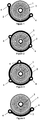
- the Figures 1 to 8 illustrate eight variants of spiral springs 1 whose outer end came from manufacture with a connecting member 2 to the frame of a timepiece.
- the rigidity of this connecting member 2 is substantially greater than that of the hairspring 1, typically 1000 times higher in the plane of the hairspring, and 10 times higher perpendicularly to the plane of the hairspring.
- the inner ends of these spiral springs are also manufactured with a fixing ferrule 3, intended to be driven, as usual, on the pivot shaft of a beam.
- the connecting member 2 extends angularly with respect to the axis of pivoting of the shaft on which the shell 3 is to be driven.
- this connecting member is able to provide the less a stable bearing surface to the spiral spring 1 as long as it is associated with a bearing surface at least partially complementary as will be seen later. These bearing surfaces are substantially parallel to the plane of the spiral spring 1.
- the connecting member 2 advantageously comprises two or even three positioning and fixing elements, consisting of openings 4 for the passage of fasteners, in particular pins or screws. These openings are preferably angularly distributed to allow to apply the connecting member 2 against the complementary bearing surface at several points of its bearing surface. In this way and within the limits of tolerances allowed, once the connecting member fixed to its complementary bearing surface, the spiral spring retains in the state of rest the three-dimensional integrity of its initial shape.
- the openings 4a may be non-circular, for example of elongate shape, to allow correction of small centering defects may come from tolerances allowed.
- the elongated opening 4a may be associated with an eccentric adjusting member, the angular displacement of which will make it possible to finely adjust the centering of the hairspring relative to the frame, by a rotation of the connecting member 2 by relative to the center of the opening 4, the clamping of the connecting member 2 occurring after the centering of the spiral spring 1.
- the fineness of the positioning is proportional to the spacing between the openings 4 and 4a.
- the eccentric adjustment member may also be associated with the circular opening 4, but this variant is less favorable for the adjustment since it implies that the two openings 4, 4a move under the effect of the adjusting member. .
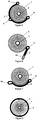
- the variant of the figure 8 relates to an annular connecting member 2, here associated with a spiral spring with two blades angularly offset by 180 °, wherein the connecting member 2 has no positioning and fixing element. Fixing such an annular connecting member 2 can be obtained for example as illustrated by the Figures 20 to 22 which will be described below.
- annular link 2 of the figure 8 is obviously also usable with a spiral spring with a single blade, as those of Figures 1 to 7 .
- annular connecting members 2 of the Figures 1-7 can also be used with spiral springs with multiple blades.
- connection member 2 is fixed directly to the balance bridge, or, advantageously, it is fixed to the balance bridge by an intermediate piece, pivotally mounted about the pivot axis of the balance shaft, which allows to adjust the landmark on the watch movement.
- the setting of the marker consists of bringing the center of the balance plate pin on the line connecting the respective pivot centers of the balance and the anchor, when the balance-sprung regulator member is in the equilibrium position.
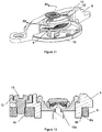
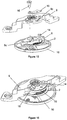
- FIGS 9 to 12 illustrate a first variant of a first embodiment, wherein the connecting member 2 comprises at least two positioning elements and corresponding bearing surfaces.
- the connecting member 2 comprises at least two positioning elements and corresponding bearing surfaces.
- a spiral spring 1 similar to that illustrated by the figure 1 .
- Two fixing pins 5 are intended to pass through the openings 4 of the connecting member 2 and to be driven into corresponding openings 6a formed in an intermediate piece 6, provided with an opening 6b concentric with the central axis of the ferrule 3 after assembling the elements of the figure 9 .
- the opening 6b of this intermediate piece 6 is intended to be fitted over a circular bearing surface of the balance bridge, coaxial with the axis of pivoting of the balance shaft, to allow the adjustment of the marker as will be seen later. .
- This intermediate piece 6 thus serves as angular positioning member of the sprung-balance regulator.
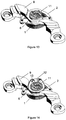
- the figure 10 shows the assembly step following the figure 9 .
- the angular positioning member 6 is pivotally mounted around the balance bridge 9, and is fixed thereto via two screws 13 passing through a clamping plate 12 on the one hand, two oblong cutouts 9a of the balance bridge 9 of FIG. secondly, to be screwed into two tapped holes 6c of the angular positioning member 6.
- the clamping plate 12 is here of arcuate shape and is mounted on the board of the balance bridge 9.
- the pivot shaft of the balance 10a and the balance 10b can be assembled to the hairspring before or after the mounting of the intermediate piece 6.
- the figure 11 shows the assembled state of this first variant.
- the adjustment of the mark of the balance spring-balance regulator member 10 can be effected by slightly loosening the two screws 13, then by pivoting the integral assembly consisting of the spring 1 whose inner end is integral with the balance shaft 10 a -spiral 10, the angular positioning member 6, and the clamping plate 12.
- the figure 12 shows a section of the figure 11 , allowing to see how the angular positioning member 6 is pivotally mounted via its opening 6b around a cylindrical surface 9b of the balance bridge 9.
- the Figures 13 and 14 illustrate a second variant of the first embodiment.
- the spiral spring 1 used corresponds to that illustrated by the figure 1 . It comprises a connecting member 2 extending about 180 ° about the pivot axis of the balance shaft, whose ends are fixed to the angular positioning member 6 pivotally mounted under the balance bridge 9 around bearing 11 pivoting one of the ends of the balance shaft.
- the figure 13 shows this angular positioning member 6 and the figure 14 shows the same elements as the figure 13 but after attaching a wafer 12 to this angular positioning member 6 by two screws 13.
- the wafer 12 and the angular positioning member 6 are mounted frictionally around the bearing 11, making it possible to adjust the mark in the traditional manner, as with a standard piton door.
- FIGs 15 and 16 illustrate a third variant of the first embodiment in which the angular positioning member 6 carries a pin 14 which allows a temporary fixing of the sprung balance regulator member 10 in a bayonet attachment opening 9c in the board of the pendulum bridge 9, as illustrated by the figure 15 .
- a foil 15 is set up with one of its ends between the board of the pendulum bridge 9 and the scope of the pin 14, while its other end is located between the board of the bridge 9 and the head of a screw single-range 16 which is screwed in abutment against the angular positioning member 6, for generating a sufficient friction torque for holding the connecting member 2 while allowing easy adjustment of the setting benchmark of the spring balance regulator 10.
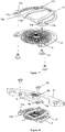
- FIGS 17 to 19 illustrate a fourth variant of the first embodiment, particularly suitable for mounting a double spiral whose outer ends of the blades are secured to a connecting member 2 in the form of a ring, in this case open ring .
- the figure 17 illustrates a first assembly step.
- the spiral 1 is here secured to the spiral support 17 by three pins 5 which pass through the openings 4 of the spiral 1 to be driven into the openings 17c of the intermediate part 17.
- the attachment points may be simple circular positioning holes 4 made in the ring that form
- the positioning holes 4 of the connecting member 2 could incorporate flexible arms (not shown) for a good positioning, or present an open contour like a split ferrule. with a certain elasticity, thus forming elastic arms so as to ensure a clamping around the pins 5.
- the figure 18 illustrates a second assembly step.
- the spiral support 17 provided with the spiral spring 1 is connected to the balance bridge 9 by the angular positioning member 6, by means of two screws 13 passing through openings 6d of the member 6 and screwed into the threaded holes 17a of the support 17.
- the good positioning of the assembly is achieved by exceeding the pins 5 which are housed in fitted openings 6e of the body 6.
- the figure 19 illustrates the complete assembly. It can be seen here that the angular positioning member 6 is provided with a ring 6b having a slot 6c which, by friction around the bearing 11 of the balance shaft, integral with the balance bridge 9, the angular positioning of the regulating organ and therefore easy adjustment of the marker.
- the clearance can be adjusted at the level of each fastener 17c to guarantee the most accurate hold possible without over-constraining the system and rendering it hyperstatic. .
- a possible choice to ensure a good assembly is to leave more play at the intermediate attachment point 17c ', which will then have a greater diameter than the others to absorb the various errors due to manufacturing tolerances of other components.
- An alternative is to define the sets of all attachment points according to the tolerances of the rigid part.
- the lower face of the spiral support 17 has a clearance 17e to avoid friction with the spiral spring.
- the arms 17d of the support 17 serve as a stop to the deformations of the spring 1 under the effect of an impact.
- FIG. 20 A second embodiment not forming part of the claimed invention is illustrated by the Figures 20 to 22 .
- This solution uses the spiral spring of the figure 8 but is also suitable for any other spiral spring provided with a similar connecting member 2. It consists in pinching axially the more rigid annular connecting member 2 between an intermediate fastening piece 7, provided with a positioning hole 7a ( figure 22 ) to receive the annular connecting member 2, and the pendulum bridge or an angular positioning member.
- This positioning wedge 7a makes it possible to set the reference point of the balance-sprung regulator member, when the inner end of the balance spring is assembled to the balance shaft.
- Two fastening screws 13 make it possible to tighten the annular connecting member 2 between the rocker bridge 9 and the intermediate fastener piece 7, the depth of the hole 7a formed in the intermediate fastening piece 7 being less than a few hundredths of a millimeter. to the thickness of the annular connecting member 2 ( figure 22 ).
- a third embodiment not forming part of the claimed invention consists in providing resilient arms 2a separating two parts of the connecting member 2, which allows, in the variant illustrated in FIGS. Figures 23 and 24 , clipping the annular connecting member 2 about pins 16 driven in the balance bridge 9, the centering being provided by two positioning elements 4b (centering cuts) formed in the connecting member 2.
- the surface of support extends over an arc of at least 60 °.
- a fourth embodiment not forming part of the claimed invention, close to the previous one, consists in providing, in addition to or instead of the elastic arms 2a, resilient arms 2c in the edge of the annular connecting member 2 ( Figures 25 and 26 ) to allow clipping of the ring in housings 17 provided for this purpose in the balance bridge 9.
- the setting of the marker can be performed by changing the angular position of the spiral, for example using tools that come s insert in passages 2d formed in the connecting member 2.
Description
La présente invention se rapporte à un mouvement horloger ou à une pièce d'horlogerie comprenant un organe régulateur balancier-spiral comportant un arbre monté pivotant sur le bâti d'une pièce d'horlogerie, dans lequel le ressort spiral dudit organe régulateur comporte au moins une lame située dans un plan, dont l'extrémité interne est destinée à être fixée audit arbre de pivotement et dont l'extrémité externe est venue de fabrication avec un organe de liaison audit bâti, la rigidité de cet organe de liaison étant sensiblement supérieure à celle du spiral.The present invention relates to a watch movement or a timepiece comprising a balance spring-balance control member comprising a shaft pivotally mounted on the frame of a timepiece, wherein the spiral spring of said regulating member comprises at least a blade located in a plane, whose inner end is intended to be fixed to said pivot shaft and whose outer end is manufactured from a connecting member to said frame, the rigidity of this connecting member being substantially greater than that of the spiral.
Plusieurs manières de solidariser l'extrémité extérieure du ressort spiral au bâti de la pièce d'horlogerie sont connues. En général, cette extrémité est fixe, à l'inverse de l'extrémité intérieure qui est solidaire d'une virole chassée sur l'arbre du balancier et qui oscille avec le régulateur balancier-spiral. Dans la plupart des cas, l'extrémité extérieure du spiral est reliée à un piton ou à une bride de fixation qui est ensuite solidarisé à un pont de balancier.Several ways of securing the outer end of the spiral spring to the frame of the timepiece are known. In general, this end is fixed, unlike the inner end which is secured to a ferrule driven on the balance shaft and oscillates with the spring balance regulator. In most cases, the outer end of the hairspring is connected to a peg or a fixing flange which is then secured to a pendulum bridge.
Une manière de solidariser l'extrémité du ressort spiral à un piton consiste à la placer dans un trou prévu à cet effet dans le piton puis à la bloquer au moyen d'une goupille ou par collage. Le piton est ensuite introduit dans un logement correspondant et fixé en position par chassage ou au moyen d'une vis.One way to secure the end of the spiral spring to a bolt is to place it in a hole provided for this purpose in the bolt and then block by means of a pin or by gluing. The stud is then introduced into a corresponding housing and fixed in position by driving or by means of a screw.
La position du ressort spiral par rapport à l'arbre de balancier doit être réglée de façon précise, car un décentrage du ressort spiral ou un défaut de perpendicularité par rapport à cet arbre génère des défauts chronométriques importants, en particulier au niveau de l'isochronisme du régulateur. Le piton doit donc être perpendiculaire au plan du ressort spiral et positionné de façon précise pour garantir un développement concentrique du ressort spiral. Avec des ressorts spiraux traditionnels en alliage métallique, une fois l'extrémité externe du ressort spiral fixée au pont de balancier, directement ou par l'intermédiaire d'un organe de réglage angulaire, les défauts induits par rapport à la forme tridimensionnelle idéale du ressort spiral sont corrigés par déformation plastique de l'extrémité extérieure du ressort spiral. Il s'agit là d'une opération très délicate qui ne peut être exécutée que par un horloger expérimenté. En outre, un tel mode de correction est naturellement inadapté aux ressorts spiraux réalisés dans une matière fragile telle que le silicium, car ce genre de matière ne se déforme pas plastiquement.The position of the spiral spring with respect to the rocker shaft must be precisely adjusted, because an off-centering of the spiral spring or a defect of perpendicularity with respect to this shaft generates significant chronometric defects, in particular at the level of isochronism of the regulator. The pin must therefore be perpendicular to the plane of the spiral spring and positioned precisely for guarantee a concentric development of the spiral spring. With traditional metal alloy spiral springs, once the outer end of the spiral spring attached to the balance bridge, directly or through an angular adjustment member, the induced defects with respect to the ideal three-dimensional shape of the spring spiral are corrected by plastic deformation of the outer end of the spiral spring. This is a very delicate operation that can only be performed by an experienced watchmaker. In addition, such a mode of correction is naturally unsuitable for spiral springs made in a fragile material such as silicon, because this kind of material does not plastically deform.
Des organes régulateurs balancier-spiral dont l'extrémité externe du ressort spiral est venue de fabrication avec un organe de liaison au bâti et dont la rigidité est sensiblement supérieure à celle du ressort spiral ont déjà été décrits, notamment dans le
Ces solutions ne permettent donc pas de résoudre le problème de la fixation de l'extrémité externe d'un ressort spiral ne nécessitant plus de correction après fixation. Il n'est en effet pas possible de garantir que de telles fixations traditionnelles n'induisent aucune déformation du ressort spiral et qu'elles permettent de garantir un développement concentrique du ressort spiral par rapport à l'axe de pivotement du balancier lors de l'oscillation du régulateur balancier-spiral, ainsi que la perpendicularité du ressort spiral à cet axe.These solutions do not therefore solve the problem of fixing the outer end of a spiral spring no longer requiring correction after fixation. It is not possible to guarantee that such traditional fasteners do not induce any deformation of the spiral spring and that they make it possible to guarantee a concentric development of the spiral spring with respect to the axis of pivoting of the balance during the oscillation of the balancer-spiral regulator, as well as the perpendicularity of the spiral spring to this axis.
Lorsque le ressort spiral est réalisé en un matériau fragile, tel que le silicium, le diamant ou le quartz, l'ajustement par déformation plastique du ressort spiral n'étant plus possible, l'utilisation d'un piton suppose alors d'avoir des tolérances de fabrication très serrées et un assemblage piton-spiral robuste pour garantir une parfaite perpendicularité ou aussi parfaite que possible entre l'axe du piton et le plan du ressort spiral, ce qui constitue évidemment une difficulté majeure à l'échelle industrielle. En effet, le serrage du piton dans son logement, par exemple au moyen d'une vis, est à lui seul déjà susceptible d'induire des modifications de son orientation et donc de la forme tridimensionnelle initiale du ressort spiral.When the spiral spring is made of a fragile material, such as silicon, diamond or quartz, the adjustment by plastic deformation of the spiral spring is no longer possible, the use of a pin then assumes to have very tight manufacturing tolerances and a robust piton-spiral assembly to ensure perfect perpendicularity or as perfect as possible between the axis of the stud and the plane of the spiral spring, which is obviously a major difficulty on an industrial scale. Indeed, the clamping of the stud in its housing, for example by means of a screw, is alone already likely to induce changes in its orientation and thus the initial three-dimensional shape of the spiral spring.
On a déjà proposé, notamment dans le
Le but de la présente invention est de remédier, au moins en partie, aux inconvénients susmentionnés.The object of the present invention is to overcome, at least in part, the aforementioned drawbacks.
A cet effet, l'invention a pour objet un mouvement d'horlogerie ou une pièce d'horlogerie selon la revendication 1.For this purpose, the invention relates to a watch movement or a timepiece according to
Différents modes de réalisation du régulateur sont définis par les revendications dépendantes 2 à 14.Different embodiments of the regulator are defined by dependent claims 2-14.
Avantageusement, le profil et l'étendue angulaire des surfaces d'appui complémentaires respectives de l'organe de liaison et du bâti ou d'un organe de positionnement angulaire du régulateur au bâti sont conformés et dimensionnés pour conserver, à l'état de repos, l'intégrité tridimensionnelle de la forme initiale du ressort spiral, après fixation des surfaces d'appui complémentaires l'une à l'autre.Advantageously, the profile and the angular extent of the respective complementary bearing surfaces of the connecting member and the frame or of an angular positioning member of the regulator to the frame are shaped and dimensioned to preserve, in the state of rest , the three-dimensional integrity of the initial shape of the spiral spring, after attachment of complementary bearing surfaces to each other.
L'étendue angulaire des surfaces d'appui peut être importante. Elle peut aller jusqu'à 360°, ce qui permet de conférer un appui extrêmement stable. De telles surfaces d'appui complémentaires peuvent être obtenues avec une très grande précision. A tolérance de fabrication égale, une grande surface d'appui, ou plusieurs surfaces d'appui distinctes disposées le long de l'organe de liaison avec un grand écart angulaire, confèrera une meilleure stabilité géométrique à l'ensemble. La surface d'appui solidaire de l'extrémité externe du ressort spiral est avantageusement venue de fabrication avec le ressort spiral, notamment lorsque le ressort spiral est découpé dans une plaquette de silicium, ce qui permet d'atteindre une très grande précision.The angular extent of the bearing surfaces can be significant. It can go up to 360 °, which gives an extremely stable support. Such complementary bearing surfaces can be obtained with very high accuracy. With equal manufacturing tolerance, a large bearing surface, or several distinct bearing surfaces arranged along the connecting member with a large angular gap, will confer a better geometric stability to the assembly. The bearing surface secured to the outer end of the spiral spring is advantageously manufactured by the spiral spring, especially when the spiral spring is cut in a silicon wafer, which achieves a very high accuracy.
Avantageusement, les surfaces d'appui respectives au moins partiellement complémentaires de l'organe de liaison et du bâti ou de l'organe de positionnement angulaire du régulateur au bâti comportent au moins deux éléments de positionnement de l'extrémité externe du ressort spiral par rapport à l'axe de l'arbre de balancier et à la fixation de l'extrémité interne du ressort spiral sur l'arbre de balancier, afin d'assurer une position desdites extrémités qui soit aussi précise que permis par les tolérances. Idéalement, ces éléments de positionnement permettent de conserver la forme initiale du ressort spiral en position de repos de l'organe régulateur.Advantageously, the respective bearing surfaces at least partially complementary to the connecting member and the frame or the angular positioning member of the regulator to the frame comprise at least two positioning elements of the outer end of the spiral spring relative to to the axis of the balance shaft and the fixing of the inner end of the spiral spring on the balance shaft, to ensure a position of said ends which is as precise as allowed by the tolerances. Ideally, these positioning elements make it possible to preserve the initial shape of the spiral spring in the rest position of the regulating member.
Les dessins annexés illustrent, schématiquement et à titre d'exemple, différentes formes d'exécution de l'organe régulateur objet de l'invention.
- Les
figures 1 à 7 sont des vues en plan de différentes formes non exhaustives que peut prendre l'organe de liaison et la (les) surface(s) d'appui solidaire(s) de l'extrémité externe du ressort spiral faisant partie de ce régulateur; - La
figure 8 est une vue en plan d'un mode de réalisation d'un ressort spiral ne faisant pas partie de l'invention revendiquée ; - La
figure 9 est une vue en perspective éclatée d'une première étape d'assemblage d'une première variante d'une première forme d'exécution ; - La
figure 10 est une vue en perspective éclatée d'une seconde étape d'assemblage de la première variante de la première forme d'exécution représentée à lafigure 9 ; - La
figure 11 est une vue en perspective assemblée de lafigure 10 ; - La
figure 12 est une coupe selon la ligne XII-XII de lafigure 11 ; - La
figure 13 est une vue en perspective d'une première étape d'assemblage d'une deuxième variante de la première forme d'exécution ; - La
figure 14 est une vue en perspective d'une seconde étape d'assemblage de la variante représentée à lafigure 13 ; - La
figure 15 est une vue en perspective éclatée d'une troisième variante de la première forme d'exécution ; - La
figure 16 est une vue en perspective assemblée de lafigure 15 ; - La
figure 17 est une vue en perspective éclatée d'une première étape d'assemblage d'une quatrième variante de la première forme d'exécution ; - La
figure 18 est une vue en perspective éclatée d'une seconde étape d'assemblage de la variante illustrée à lafigure 17 ; - La
figure 19 est une vue en perspective assemblée de lafigure 18 ; - Les
figures 20 à 22 sont des vues d'un assemblage ne faisant pas partie de l'invention revendiquée ; - Les
figures 23 et 24 sont des vues d'un assemblage ne faisant pas partie de l'invention revendiquée ; - Les
figures 25 et 26 sont des vues d'un assemblage ne faisant pas partie de l'invention revendiquée.
- The
Figures 1 to 7 are plan views of various non-exhaustive forms that may be taken by the connecting member and the bearing surface (s) integral with the outer end of the spiral spring forming part of this regulator; - The
figure 8 is a plan view of an embodiment of a spiral spring not forming part of the claimed invention; - The
figure 9 is an exploded perspective view of a first assembly step of a first variant of a first embodiment; - The
figure 10 is an exploded perspective view of a second assembly step of the first variant of the first embodiment shown in FIG.figure 9 ; - The
figure 11 is an assembled perspective view of thefigure 10 ; - The
figure 12 is a section along the line XII-XII of thefigure 11 ; - The
figure 13 is a perspective view of a first assembly step of a second variant of the first embodiment; - The
figure 14 is a perspective view of a second assembly step of the variant shown in FIG.figure 13 ; - The
figure 15 is an exploded perspective view of a third variant of the first embodiment; - The
figure 16 is an assembled perspective view of thefigure 15 ; - The
figure 17 is an exploded perspective view of a first assembly step of a fourth variant of the first embodiment; - The
figure 18 is an exploded perspective view of a second assembly step of the variant illustrated in FIG.figure 17 ; - The
figure 19 is an assembled perspective view of thefigure 18 ; - The
Figures 20 to 22 are views of an assembly not forming part of the claimed invention; - The
Figures 23 and 24 are views of an assembly not forming part of the claimed invention; - The
Figures 25 and 26 are views of an assembly not forming part of the claimed invention.
Les
Selon les variantes des
Comme illustré par les
La variante de la
L'organe de liaison annulaire 2 de la
Différentes solutions sont possibles pour fixer l'organe de liaison 2 au bâti du mouvement d'horlogerie. Soit cet organe de liaison est fixé directement au pont de balancier, soit, avantageusement, il est fixé au pont de balancier par une pièce intermédiaire, montée pivotante autour de l'axe de pivotement de l'arbre du balancier, ce qui permet de régler le repère sur le mouvement d'horlogerie. Le réglage du repère consiste à amener le centre de la cheville de plateau du balancier sur la ligne reliant les centres de pivotement respectifs du balancier et de l'ancre, lorsque l'organe régulateur balancier-spiral est en position d'équilibre.Different solutions are possible for fixing the connecting
Les
La
La
La
Les
Les
Les
La
Les points de fixation peuvent être de simples trous de positionnement circulaires 4 réalisés dans l'anneau que forme l'organe de liaison 2. En variante, les trous de positionnement 4 de l'organe de liaison 2 pourraient intégrer des bras flexibles (non représentés) pour un bon positionnement, ou présenter un contour ouvert à l'instar d'une virole fendue avec une certaine élasticité, formant ainsi des bras élastiques de manière à assurer un serrage autour des goupilles 5.The attachment points may be simple
La
La
Les tolérances de fabrication du support de spiral 17 étant plus larges que celles du ressort spiral 1, on pourra ajuster le jeu au niveau de chaque fixation 17c pour garantir la tenue la plus précise possible sans pour autant sur-contraindre le système et le rendre hyperstatique. Un choix possible pour garantir un bon assemblage est de laisser plus de jeu au niveau du point de fixation intermédiaire 17c', qui présentera alors un diamètre plus important que les autres pour absorber les différentes erreurs dues aux tolérances de fabrication des autres composants. Une alternative consiste à définir les jeux de tous les points d'attache en fonction des tolérances de la pièce rigide.Since the manufacturing tolerances of the
La face inférieure du support de spiral 17 présente un dégagement 17e pour éviter le frottement avec le ressort spiral. Les bras 17d du support 17 servent de butée aux déformations du spiral 1 sous l'effet d'un choc.The lower face of the
Une deuxième forme d'exécution ne faisant pas partie de l'invention revendiquée est illustrée par les
Il n'y a alors pas au moins deux points de fixation ou de pitonnage discrets, mais une fixation sur une surface d'appui s'étendant sur un arc de cercle d'au moins 60°. Cette solution permet un réglage aisé du repère et facilite les opérations de vérification et d'assemblage. En effet, aucun élément ne recouvre le ressort spiral, et toutes les spires du ressort sont alors visibles.There are then not at least two discrete fixing or pegging points, but a fixation on a bearing surface extending over an arc of at least 60 °. This solution allows easy adjustment of the marker and facilitates verification and assembly operations. Indeed, no element covers the spiral spring, and all turns of the spring are then visible.
Une troisième forme d'exécution ne faisant pas partie de l'invention revendiquée consiste à ménager des bras élastiques 2a séparant deux parties de l'organe de liaison annulaire 2, ce qui permet, dans la variante illustrée aux
Une quatrième forme d'exécution ne faisant pas partie de l'invention revendiquée, proche de la précédente, consiste à ménager, en plus ou au lieu des bras élastiques 2a, des bras élastiques 2c dans le bord de l'organe de liaison annulaire 2 (
Ces différentes caractéristiques, notamment les différentes caractéristiques des différentes formes d'exécution, et/ou ces différentes formes d'exécution peuvent, sauf incompatibilité, être combinées les unes aux autres.These different characteristics, in particular the different characteristics of the various embodiments, and / or these different embodiments may, unless they are incompatible, be combined with each other.
Claims (14)
- A timepiece movement or a timepiece including a movement, the movement comprising a member (6) for the angular positioning (6) and spiral-spring and balance regulating member (10) including a shaft designed to be mounted pivotably according to a pivoting axis on a frame of the movement, the regulating member being such that the spiral spring (1) of the regulating member (10) includes at least one blade located in a plane, whose inner end is designed to be fixed to the pivot shaft and whose outer end is made in one piece with a member (2) for connection to the member (6) for the angular positioning of the regulating member (10) on the frame, the rigidity of this connecting member (2) being substantially greater than that of the at least one blade, wherein the connecting member (2) on one hand, and the member (6) for the angular positioning of the regulating member (10) on the frame, on the other hand, both have respective bearing surfaces which are at least partially complementary and substantially parallel to the plane of the spiral, fixing means (5) being used to join these complementary bearing surfaces, and wherein said connecting member (2) includes at least two positioning and fixing elements (4) distributed angularly about the pivot axis and cooperating with said fixing means (5).
- The timepiece movement or the timepiece as claimed in claim 1, wherein the bearing surfaces extend over an angular portion of more than 60°about the pivot axis.
- The timepiece movement or the timepiece as claimed in claim 1 or 2, wherein the bearing surfaces are continuous.
- The timepiece movement or the timepiece as claimed in one of the preceding claims, wherein a single surface extends for more than 60° about the pivot axis of the shaft, or for more than 120° about the pivot axis of the shaft, or for 180° or more about the pivot axis of the shaft.
- The timepiece movement or the timepiece as claimed in claim 1 or 2, wherein at least one of the bearing surfaces is discontinuous.
- The timepiece movement or the timepiece as claimed in claim 5, wherein two elements of a surface are positioned at more than 60° to each other about the pivot axis of the shaft, or at more than 120° to each other about the pivot axis of the shaft, or at 180° to each other or more about the pivot axis of the shaft, and/or wherein each of the two elements extends over more than 10°, or more than 20°, about the pivot axis of the shaft.
- The timepiece movement or the timepiece as claimed in one of the preceding claims, wherein the profile and angular extension of the at least partially complementary respective bearing surfaces have shapes and sizes with respect to the pivot axis of the shaft such that the three-dimensional integrity of the initial shape of the spiral (1) is preserved in the resting state after the complementary bearing surfaces have been fixed to each other.
- The timepiece movement or the timepiece as claimed in one of the preceding claims, wherein the angular interval between the positioning and fixing elements is in the range from 60° to 180°.
- The timepiece movement or the timepiece as claimed in one of the preceding claims, wherein the angular positioning member (6) is mounted pivotably about the bearing (11) for the pivoting of the balance wheel shaft on the balance bridge (9).
- The timepiece movement or the timepiece as claimed in one of the preceding claims, wherein the connecting member (2) is an annular member.
- The timepiece movement or the timepiece as claimed in claim 10, wherein the annular connecting member (2) is positioned between an intermediate fixing part (7), which has a positioning recess (7a) for receiving the annular connecting member (2), and the lower face of the balance bridge (9), clamping means (8) being designed to clamp the annular connecting member (2) between the intermediate part (7) and the balance bridge (9).
- The timepiece movement or the timepiece as claimed in one of claims 1 to 10, wherein the angular positioning member (6) has a shouldered pin (14) to engage with a bayonet fixing opening (9a) in the balance bridge (9), a foil (15) being positioned between the plate of the balance bridge (9) and, on the one hand, the shoulder of the pin (14), and on the other hand a shouldered screw (16) screwed so as to bear against the connecting member (2), this foil creating a frictional torque to retain the connecting member (2) while allowing the reference position of the regulating member to be set.
- The timepiece movement or the timepiece as claimed in one of claims 1 to 10, wherein the spiral (1) includes two blades whose respective outer ends are fastened to the connecting member (2), the means for fixing the spiral to the angular positioning member (6) including a more rigid spiral support element (17), fixed to the connecting member with the aid of screws 18.
- The timepiece movement or the timepiece as claimed in one of the preceding claims, wherein the angular positioning member (6) includes a split ring (6b) for its frictional connection around the bearing (11) of the balance wheel shaft, fastened to the balance bridge (9).
Priority Applications (1)
| Application Number | Priority Date | Filing Date | Title |
|---|---|---|---|
| EP11405331.7A EP2437126B1 (en) | 2010-10-04 | 2011-09-27 | Balance wheel-hairspring regulator |
Applications Claiming Priority (2)
| Application Number | Priority Date | Filing Date | Title |
|---|---|---|---|
| EP10405183 | 2010-10-04 | ||
| EP11405331.7A EP2437126B1 (en) | 2010-10-04 | 2011-09-27 | Balance wheel-hairspring regulator |
Publications (2)
| Publication Number | Publication Date |
|---|---|
| EP2437126A1 EP2437126A1 (en) | 2012-04-04 |
| EP2437126B1 true EP2437126B1 (en) | 2019-03-27 |
Family
ID=43707756
Family Applications (1)
| Application Number | Title | Priority Date | Filing Date |
|---|---|---|---|
| EP11405331.7A Active EP2437126B1 (en) | 2010-10-04 | 2011-09-27 | Balance wheel-hairspring regulator |
Country Status (5)
| Country | Link |
|---|---|
| US (1) | US8672535B2 (en) |
| EP (1) | EP2437126B1 (en) |
| JP (1) | JP5886585B2 (en) |
| CN (1) | CN102540849B (en) |
| CH (1) | CH703935B1 (en) |
Cited By (1)
| Publication number | Priority date | Publication date | Assignee | Title |
|---|---|---|---|---|
| EP4099101A1 (en) | 2021-06-03 | 2022-12-07 | Rolex Sa | Device for assembling a timepiece oscillator |
Families Citing this family (15)
| Publication number | Priority date | Publication date | Assignee | Title |
|---|---|---|---|---|
| CH707814A2 (en) * | 2013-03-19 | 2014-09-30 | Nivarox Sa | Clockwork mechanism spiral adjustment. |
| CH707815B1 (en) | 2013-03-19 | 2017-05-31 | Nivarox Far Sa | Subassembly of a clockwork escapement mechanism comprising a spiral spring. |
| EP2781969B1 (en) * | 2013-03-19 | 2017-05-03 | Nivarox-FAR S.A. | Non-removable one-piece timepiece component |
| EP2799937B1 (en) | 2013-05-01 | 2020-09-16 | Rolex Sa | Shock-proof bearing for an horological balance |
| CH708731B1 (en) | 2013-10-18 | 2017-12-15 | Montres Breguet Sa | Elastic display indicator, in particular an elastic needle, with variable radial extension. |
| CH710188A2 (en) * | 2014-09-26 | 2016-03-31 | Eta Sa Manufacture Horlogère Suisse | Resonator paraxial and isochronous watchmaking. |
| JP6710041B2 (en) | 2014-11-27 | 2020-06-17 | ロレックス・ソシエテ・アノニムRolex Sa | Balancing spring fixing system |
| EP3147728A1 (en) * | 2015-09-24 | 2017-03-29 | Harry Winston SA | Mechanism for positioning a toothed wheel in a clock movement |
| JP6355282B1 (en) * | 2017-03-13 | 2018-07-11 | セイコーインスツル株式会社 | Fixed structure for mobile device parts |
| EP3812846A1 (en) * | 2019-10-24 | 2021-04-28 | ETA SA Manufacture Horlogère Suisse | Device for assembly and alignment, in particular for a timepiece resonator mechanism |
| EP3859451A1 (en) * | 2020-01-29 | 2021-08-04 | ETA SA Manufacture Horlogère Suisse | Movement endshake adjustment device |
| JP6766284B1 (en) * | 2020-03-02 | 2020-10-07 | セイコーウオッチ株式会社 | Swirl springs, torque generators, watch movements and watches |
| EP4006649A1 (en) * | 2020-11-27 | 2022-06-01 | ETA SA Manufacture Horlogère Suisse | Attachment device for adjusting the movement of a balance |
| CH718694A2 (en) * | 2021-06-03 | 2022-12-15 | Rolex Sa | Process for manufacturing a watch movement component. |
| EP4286960A1 (en) * | 2022-06-02 | 2023-12-06 | ETA SA Manufacture Horlogère Suisse | Timepiece regulator provided with an index-assembly system |
Family Cites Families (16)
| Publication number | Priority date | Publication date | Assignee | Title |
|---|---|---|---|---|
| US1023140A (en) * | 1908-12-11 | 1912-04-16 | Frederic Ecaubert | Escapement-regulator. |
| US3154912A (en) * | 1963-01-22 | 1964-11-03 | Pinkas David | Means for mounting and regulating the outer end of a spiral spring |
| JPS4711179Y1 (en) * | 1968-10-04 | 1972-04-25 | ||
| US3943701A (en) * | 1975-01-08 | 1976-03-16 | Timex Corporation | Regulator and balance bridge arrangement for a horological device |
| JPS5244047Y1 (en) * | 1976-01-08 | 1977-10-06 | ||
| US6612734B1 (en) * | 1999-07-29 | 2003-09-02 | Seiko Instruments Inc. | Mechanical timepiece with stud adjustment mechanism |
| EP1515200A1 (en) | 2003-09-10 | 2005-03-16 | Patek Philippe S.A. | Hairspring for timepiece |
| ATE363676T1 (en) * | 2003-10-01 | 2007-06-15 | Asulab Sa | CLOCK WITH A MECHANICAL MOVEMENT COUPLED WITH AN ELECTRONIC REGULATOR |
| DE10345918A1 (en) * | 2003-10-02 | 2005-05-12 | Lange Uhren Gmbh | oscillating system |
| CH697208A5 (en) * | 2004-04-08 | 2008-06-25 | Coredem Sa | sprung balance assembly for mechanical watch movement. |
| GB0509886D0 (en) * | 2005-05-14 | 2005-06-22 | Levingston Gideon R | Balance wheel mass and regulating element assembly and balance wheel and balance spring manufacturing processes for horolongical oscillator mechanisms |
| JP5606675B2 (en) * | 2005-05-14 | 2014-10-15 | カーボンタイム・リミテッド | Balance spring and method for forming the same |
| CH699746B1 (en) * | 2005-12-14 | 2010-04-30 | Patek Philippe Sa Geneve | Mechanical device for putting into beat of the exhaust of a regulating member. |
| DE102006052245A1 (en) | 2006-11-03 | 2008-05-08 | Lange Uhren Gmbh | Oscillation system for a clock |
| EP2151722B8 (en) | 2008-07-29 | 2021-03-31 | Rolex Sa | Hairspring for balance-spring resonator |
| WO2010088891A2 (en) * | 2009-02-06 | 2010-08-12 | Konrad Damasko | Mechanical oscillating system for watches and functional element for watches |
-
2011
- 2011-09-27 CH CH01586/11A patent/CH703935B1/en unknown
- 2011-09-27 EP EP11405331.7A patent/EP2437126B1/en active Active
- 2011-09-29 US US13/248,423 patent/US8672535B2/en active Active
- 2011-09-30 CN CN201110348467.1A patent/CN102540849B/en active Active
- 2011-10-03 JP JP2011218906A patent/JP5886585B2/en active Active
Non-Patent Citations (1)
| Title |
|---|
| None * |
Cited By (1)
| Publication number | Priority date | Publication date | Assignee | Title |
|---|---|---|---|---|
| EP4099101A1 (en) | 2021-06-03 | 2022-12-07 | Rolex Sa | Device for assembling a timepiece oscillator |
Also Published As
| Publication number | Publication date |
|---|---|
| US20120082010A1 (en) | 2012-04-05 |
| CN102540849B (en) | 2015-10-07 |
| CH703935A2 (en) | 2012-04-13 |
| CH703935B1 (en) | 2017-04-13 |
| JP5886585B2 (en) | 2016-03-16 |
| US8672535B2 (en) | 2014-03-18 |
| EP2437126A1 (en) | 2012-04-04 |
| JP2012078358A (en) | 2012-04-19 |
| CN102540849A (en) | 2012-07-04 |
Similar Documents
| Publication | Publication Date | Title |
|---|---|---|
| EP2437126B1 (en) | Balance wheel-hairspring regulator | |
| EP2887154B1 (en) | Mechanism for attaching a balance-spring stud to a balance bridge and regulating device with balance-hairspring including such a mechanism | |
| EP2799937B1 (en) | Shock-proof bearing for an horological balance | |
| EP2804055B1 (en) | Assembly consisting of a stud and a stud support | |
| EP3172626B1 (en) | Pivot with blade | |
| EP2743781B1 (en) | Device for assembly by locking a joint | |
| EP4009115A1 (en) | Hairspring for timepiece resonator mechanism provided with a means for adjusting rigidity | |
| CH701075B1 (en) | Cannon-pinion wheel and arbor assembly for clock movement, has wheel whose hub is connected to felloe to form rigid, monolithic and effectively non-deformable assembly, and pad with surface provided in contact with periphery of arbor | |
| EP3432081B1 (en) | Timepiece assembly | |
| WO2017207880A1 (en) | Decorative object, such as an item of jewellery, comprising a body and a decorative element reversibly attached to the body | |
| CH705605A2 (en) | Device for adjusting length of coil of beam-spiral type oscillator, has racket arranged with adjustable orientation on clockwork movement frame, where racket carries clamping units of terminal portion of coil to define length of coil | |
| EP3037896B1 (en) | Detachable stud support | |
| EP3432082B1 (en) | Regulating mechanism | |
| EP3037895B1 (en) | Detachable stud support | |
| EP3839651A1 (en) | Mechanical timepiece oscillator with flexible guide | |
| CH713999A1 (en) | Watch component intended to be fixed on an axis. | |
| CH716553B1 (en) | Watchmaking mechanism for generating a friction limiting the torque transmitted between two rotatitves parts and friction spring for such a mechanism. | |
| CH714249B1 (en) | Oscillator for watch movement. | |
| EP4327163A1 (en) | Assembly intended to equip a timepiece or watch mechanism and comprising at least one resilient element and at least one first and one second watch component | |
| EP4296790A1 (en) | Stud support device | |
| CH707341A2 (en) | Assembly system for assembling fulcrum pin in opening of part e.g. wheel, using intermediate portion in timepiece, has intermediate portion received against shoulder of part, and blocked laterally by resilient locking device of part | |
| CH719802A2 (en) | Eyebolt holder intended to be mounted on a balance bridge of a mechanical watch movement. | |
| CH710571A2 (en) | Holding assembly or support of a timepiece balance spring with a peak and a carrier peak. | |
| CH706640A2 (en) | Shock-absorbing bearing for axis of mobile of clockwork movement of timepiece, has fixing units arranged to fix resilient units at support irrespective of angular orientation of resilient units relative to pivot module and housing | |
| CH698699B1 (en) | Whiplash timepiece. |
Legal Events
| Date | Code | Title | Description |
|---|---|---|---|
| PUAI | Public reference made under article 153(3) epc to a published international application that has entered the european phase |
Free format text: ORIGINAL CODE: 0009012 |
|
| AK | Designated contracting states |
Kind code of ref document: A1 Designated state(s): AL AT BE BG CH CY CZ DE DK EE ES FI FR GB GR HR HU IE IS IT LI LT LU LV MC MK MT NL NO PL PT RO RS SE SI SK SM TR |
|
| AX | Request for extension of the european patent |
Extension state: BA ME |
|
| 17P | Request for examination filed |
Effective date: 20121004 |
|
| 17Q | First examination report despatched |
Effective date: 20130212 |
|
| GRAP | Despatch of communication of intention to grant a patent |
Free format text: ORIGINAL CODE: EPIDOSNIGR1 |
|
| STAA | Information on the status of an ep patent application or granted ep patent |
Free format text: STATUS: GRANT OF PATENT IS INTENDED |
|
| INTG | Intention to grant announced |
Effective date: 20170623 |
|
| GRAJ | Information related to disapproval of communication of intention to grant by the applicant or resumption of examination proceedings by the epo deleted |
Free format text: ORIGINAL CODE: EPIDOSDIGR1 |
|
| GRAP | Despatch of communication of intention to grant a patent |
Free format text: ORIGINAL CODE: EPIDOSNIGR1 |
|
| GRAJ | Information related to disapproval of communication of intention to grant by the applicant or resumption of examination proceedings by the epo deleted |
Free format text: ORIGINAL CODE: EPIDOSDIGR1 |
|
| STAA | Information on the status of an ep patent application or granted ep patent |
Free format text: STATUS: EXAMINATION IS IN PROGRESS |
|
| INTG | Intention to grant announced |
Effective date: 20170911 |
|
| INTC | Intention to grant announced (deleted) | ||
| GRAP | Despatch of communication of intention to grant a patent |
Free format text: ORIGINAL CODE: EPIDOSNIGR1 |
|
| STAA | Information on the status of an ep patent application or granted ep patent |
Free format text: STATUS: GRANT OF PATENT IS INTENDED |
|
| INTG | Intention to grant announced |
Effective date: 20171117 |
|
| INTG | Intention to grant announced |
Effective date: 20171117 |
|
| GRAJ | Information related to disapproval of communication of intention to grant by the applicant or resumption of examination proceedings by the epo deleted |
Free format text: ORIGINAL CODE: EPIDOSDIGR1 |
|
| GRAP | Despatch of communication of intention to grant a patent |
Free format text: ORIGINAL CODE: EPIDOSNIGR1 |
|
| GRAJ | Information related to disapproval of communication of intention to grant by the applicant or resumption of examination proceedings by the epo deleted |
Free format text: ORIGINAL CODE: EPIDOSDIGR1 |
|
| GRAJ | Information related to disapproval of communication of intention to grant by the applicant or resumption of examination proceedings by the epo deleted |
Free format text: ORIGINAL CODE: EPIDOSDIGR1 |
|
| GRAP | Despatch of communication of intention to grant a patent |
Free format text: ORIGINAL CODE: EPIDOSNIGR1 |
|
| GRAP | Despatch of communication of intention to grant a patent |
Free format text: ORIGINAL CODE: EPIDOSNIGR1 |
|
| GRAJ | Information related to disapproval of communication of intention to grant by the applicant or resumption of examination proceedings by the epo deleted |
Free format text: ORIGINAL CODE: EPIDOSDIGR1 |
|
| GRAP | Despatch of communication of intention to grant a patent |
Free format text: ORIGINAL CODE: EPIDOSNIGR1 |
|
| GRAJ | Information related to disapproval of communication of intention to grant by the applicant or resumption of examination proceedings by the epo deleted |
Free format text: ORIGINAL CODE: EPIDOSDIGR1 |
|
| INTG | Intention to grant announced |
Effective date: 20180123 |
|
| GRAP | Despatch of communication of intention to grant a patent |
Free format text: ORIGINAL CODE: EPIDOSNIGR1 |
|
| INTG | Intention to grant announced |
Effective date: 20180206 |
|
| INTG | Intention to grant announced |
Effective date: 20180216 |
|
| INTG | Intention to grant announced |
Effective date: 20180226 |
|
| INTG | Intention to grant announced |
Effective date: 20180305 |
|
| GRAJ | Information related to disapproval of communication of intention to grant by the applicant or resumption of examination proceedings by the epo deleted |
Free format text: ORIGINAL CODE: EPIDOSDIGR1 |
|
| STAA | Information on the status of an ep patent application or granted ep patent |
Free format text: STATUS: EXAMINATION IS IN PROGRESS |
|
| INTC | Intention to grant announced (deleted) | ||
| GRAP | Despatch of communication of intention to grant a patent |
Free format text: ORIGINAL CODE: EPIDOSNIGR1 |
|
| STAA | Information on the status of an ep patent application or granted ep patent |
Free format text: STATUS: GRANT OF PATENT IS INTENDED |
|
| INTG | Intention to grant announced |
Effective date: 20180917 |
|
| GRAJ | Information related to disapproval of communication of intention to grant by the applicant or resumption of examination proceedings by the epo deleted |
Free format text: ORIGINAL CODE: EPIDOSDIGR1 |
|
| STAA | Information on the status of an ep patent application or granted ep patent |
Free format text: STATUS: EXAMINATION IS IN PROGRESS |
|
| GRAR | Information related to intention to grant a patent recorded |
Free format text: ORIGINAL CODE: EPIDOSNIGR71 |
|
| GRAS | Grant fee paid |
Free format text: ORIGINAL CODE: EPIDOSNIGR3 |
|
| STAA | Information on the status of an ep patent application or granted ep patent |
Free format text: STATUS: GRANT OF PATENT IS INTENDED |
|
| GRAA | (expected) grant |
Free format text: ORIGINAL CODE: 0009210 |
|
| STAA | Information on the status of an ep patent application or granted ep patent |
Free format text: STATUS: THE PATENT HAS BEEN GRANTED |
|
| INTC | Intention to grant announced (deleted) | ||
| INTG | Intention to grant announced |
Effective date: 20190214 |
|
| AK | Designated contracting states |
Kind code of ref document: B1 Designated state(s): AL AT BE BG CH CY CZ DE DK EE ES FI FR GB GR HR HU IE IS IT LI LT LU LV MC MK MT NL NO PL PT RO RS SE SI SK SM TR |
|
| REG | Reference to a national code |
Ref country code: GB Ref legal event code: FG4D Free format text: NOT ENGLISH |
|
| REG | Reference to a national code |
Ref country code: CH Ref legal event code: EP |
|
| REG | Reference to a national code |
Ref country code: AT Ref legal event code: REF Ref document number: 1113801 Country of ref document: AT Kind code of ref document: T Effective date: 20190415 |
|
| REG | Reference to a national code |
Ref country code: IE Ref legal event code: FG4D Free format text: LANGUAGE OF EP DOCUMENT: FRENCH |
|
| REG | Reference to a national code |
Ref country code: DE Ref legal event code: R096 Ref document number: 602011057487 Country of ref document: DE |
|
| REG | Reference to a national code |
Ref country code: CH Ref legal event code: NV Representative=s name: MOINAS AND SAVOYE SA, CH |
|
| PG25 | Lapsed in a contracting state [announced via postgrant information from national office to epo] |
Ref country code: FI Free format text: LAPSE BECAUSE OF FAILURE TO SUBMIT A TRANSLATION OF THE DESCRIPTION OR TO PAY THE FEE WITHIN THE PRESCRIBED TIME-LIMIT Effective date: 20190327 Ref country code: NO Free format text: LAPSE BECAUSE OF FAILURE TO SUBMIT A TRANSLATION OF THE DESCRIPTION OR TO PAY THE FEE WITHIN THE PRESCRIBED TIME-LIMIT Effective date: 20190627 Ref country code: LT Free format text: LAPSE BECAUSE OF FAILURE TO SUBMIT A TRANSLATION OF THE DESCRIPTION OR TO PAY THE FEE WITHIN THE PRESCRIBED TIME-LIMIT Effective date: 20190327 Ref country code: SE Free format text: LAPSE BECAUSE OF FAILURE TO SUBMIT A TRANSLATION OF THE DESCRIPTION OR TO PAY THE FEE WITHIN THE PRESCRIBED TIME-LIMIT Effective date: 20190327 |
|
| REG | Reference to a national code |
Ref country code: NL Ref legal event code: MP Effective date: 20190327 |
|
| PG25 | Lapsed in a contracting state [announced via postgrant information from national office to epo] |
Ref country code: RS Free format text: LAPSE BECAUSE OF FAILURE TO SUBMIT A TRANSLATION OF THE DESCRIPTION OR TO PAY THE FEE WITHIN THE PRESCRIBED TIME-LIMIT Effective date: 20190327 Ref country code: NL Free format text: LAPSE BECAUSE OF FAILURE TO SUBMIT A TRANSLATION OF THE DESCRIPTION OR TO PAY THE FEE WITHIN THE PRESCRIBED TIME-LIMIT Effective date: 20190327 Ref country code: BG Free format text: LAPSE BECAUSE OF FAILURE TO SUBMIT A TRANSLATION OF THE DESCRIPTION OR TO PAY THE FEE WITHIN THE PRESCRIBED TIME-LIMIT Effective date: 20190627 Ref country code: HR Free format text: LAPSE BECAUSE OF FAILURE TO SUBMIT A TRANSLATION OF THE DESCRIPTION OR TO PAY THE FEE WITHIN THE PRESCRIBED TIME-LIMIT Effective date: 20190327 Ref country code: GR Free format text: LAPSE BECAUSE OF FAILURE TO SUBMIT A TRANSLATION OF THE DESCRIPTION OR TO PAY THE FEE WITHIN THE PRESCRIBED TIME-LIMIT Effective date: 20190628 Ref country code: LV Free format text: LAPSE BECAUSE OF FAILURE TO SUBMIT A TRANSLATION OF THE DESCRIPTION OR TO PAY THE FEE WITHIN THE PRESCRIBED TIME-LIMIT Effective date: 20190327 |
|
| REG | Reference to a national code |
Ref country code: AT Ref legal event code: MK05 Ref document number: 1113801 Country of ref document: AT Kind code of ref document: T Effective date: 20190327 |
|
| PG25 | Lapsed in a contracting state [announced via postgrant information from national office to epo] |
Ref country code: EE Free format text: LAPSE BECAUSE OF FAILURE TO SUBMIT A TRANSLATION OF THE DESCRIPTION OR TO PAY THE FEE WITHIN THE PRESCRIBED TIME-LIMIT Effective date: 20190327 Ref country code: AL Free format text: LAPSE BECAUSE OF FAILURE TO SUBMIT A TRANSLATION OF THE DESCRIPTION OR TO PAY THE FEE WITHIN THE PRESCRIBED TIME-LIMIT Effective date: 20190327 Ref country code: PT Free format text: LAPSE BECAUSE OF FAILURE TO SUBMIT A TRANSLATION OF THE DESCRIPTION OR TO PAY THE FEE WITHIN THE PRESCRIBED TIME-LIMIT Effective date: 20190727 Ref country code: IT Free format text: LAPSE BECAUSE OF FAILURE TO SUBMIT A TRANSLATION OF THE DESCRIPTION OR TO PAY THE FEE WITHIN THE PRESCRIBED TIME-LIMIT Effective date: 20190327 Ref country code: RO Free format text: LAPSE BECAUSE OF FAILURE TO SUBMIT A TRANSLATION OF THE DESCRIPTION OR TO PAY THE FEE WITHIN THE PRESCRIBED TIME-LIMIT Effective date: 20190327 Ref country code: CZ Free format text: LAPSE BECAUSE OF FAILURE TO SUBMIT A TRANSLATION OF THE DESCRIPTION OR TO PAY THE FEE WITHIN THE PRESCRIBED TIME-LIMIT Effective date: 20190327 Ref country code: SK Free format text: LAPSE BECAUSE OF FAILURE TO SUBMIT A TRANSLATION OF THE DESCRIPTION OR TO PAY THE FEE WITHIN THE PRESCRIBED TIME-LIMIT Effective date: 20190327 Ref country code: ES Free format text: LAPSE BECAUSE OF FAILURE TO SUBMIT A TRANSLATION OF THE DESCRIPTION OR TO PAY THE FEE WITHIN THE PRESCRIBED TIME-LIMIT Effective date: 20190327 |
|
| PG25 | Lapsed in a contracting state [announced via postgrant information from national office to epo] |
Ref country code: SM Free format text: LAPSE BECAUSE OF FAILURE TO SUBMIT A TRANSLATION OF THE DESCRIPTION OR TO PAY THE FEE WITHIN THE PRESCRIBED TIME-LIMIT Effective date: 20190327 Ref country code: PL Free format text: LAPSE BECAUSE OF FAILURE TO SUBMIT A TRANSLATION OF THE DESCRIPTION OR TO PAY THE FEE WITHIN THE PRESCRIBED TIME-LIMIT Effective date: 20190327 |
|
| PG25 | Lapsed in a contracting state [announced via postgrant information from national office to epo] |
Ref country code: AT Free format text: LAPSE BECAUSE OF FAILURE TO SUBMIT A TRANSLATION OF THE DESCRIPTION OR TO PAY THE FEE WITHIN THE PRESCRIBED TIME-LIMIT Effective date: 20190327 Ref country code: IS Free format text: LAPSE BECAUSE OF FAILURE TO SUBMIT A TRANSLATION OF THE DESCRIPTION OR TO PAY THE FEE WITHIN THE PRESCRIBED TIME-LIMIT Effective date: 20190727 |
|
| REG | Reference to a national code |
Ref country code: DE Ref legal event code: R097 Ref document number: 602011057487 Country of ref document: DE |
|
| PG25 | Lapsed in a contracting state [announced via postgrant information from national office to epo] |
Ref country code: DK Free format text: LAPSE BECAUSE OF FAILURE TO SUBMIT A TRANSLATION OF THE DESCRIPTION OR TO PAY THE FEE WITHIN THE PRESCRIBED TIME-LIMIT Effective date: 20190327 |
|
| PLBE | No opposition filed within time limit |
Free format text: ORIGINAL CODE: 0009261 |
|
| STAA | Information on the status of an ep patent application or granted ep patent |
Free format text: STATUS: NO OPPOSITION FILED WITHIN TIME LIMIT |
|
| PG25 | Lapsed in a contracting state [announced via postgrant information from national office to epo] |
Ref country code: SI Free format text: LAPSE BECAUSE OF FAILURE TO SUBMIT A TRANSLATION OF THE DESCRIPTION OR TO PAY THE FEE WITHIN THE PRESCRIBED TIME-LIMIT Effective date: 20190327 |
|
| 26N | No opposition filed |
Effective date: 20200103 |
|
| PG25 | Lapsed in a contracting state [announced via postgrant information from national office to epo] |
Ref country code: TR Free format text: LAPSE BECAUSE OF FAILURE TO SUBMIT A TRANSLATION OF THE DESCRIPTION OR TO PAY THE FEE WITHIN THE PRESCRIBED TIME-LIMIT Effective date: 20190327 |
|
| PG25 | Lapsed in a contracting state [announced via postgrant information from national office to epo] |
Ref country code: MC Free format text: LAPSE BECAUSE OF FAILURE TO SUBMIT A TRANSLATION OF THE DESCRIPTION OR TO PAY THE FEE WITHIN THE PRESCRIBED TIME-LIMIT Effective date: 20190327 |
|
| PG25 | Lapsed in a contracting state [announced via postgrant information from national office to epo] |
Ref country code: LU Free format text: LAPSE BECAUSE OF NON-PAYMENT OF DUE FEES Effective date: 20190927 Ref country code: IE Free format text: LAPSE BECAUSE OF NON-PAYMENT OF DUE FEES Effective date: 20190927 |
|
| REG | Reference to a national code |
Ref country code: BE Ref legal event code: MM Effective date: 20190930 |
|
| PG25 | Lapsed in a contracting state [announced via postgrant information from national office to epo] |
Ref country code: BE Free format text: LAPSE BECAUSE OF NON-PAYMENT OF DUE FEES Effective date: 20190930 |
|
| PG25 | Lapsed in a contracting state [announced via postgrant information from national office to epo] |
Ref country code: CY Free format text: LAPSE BECAUSE OF FAILURE TO SUBMIT A TRANSLATION OF THE DESCRIPTION OR TO PAY THE FEE WITHIN THE PRESCRIBED TIME-LIMIT Effective date: 20190327 |
|
| PG25 | Lapsed in a contracting state [announced via postgrant information from national office to epo] |
Ref country code: MT Free format text: LAPSE BECAUSE OF FAILURE TO SUBMIT A TRANSLATION OF THE DESCRIPTION OR TO PAY THE FEE WITHIN THE PRESCRIBED TIME-LIMIT Effective date: 20190327 Ref country code: HU Free format text: LAPSE BECAUSE OF FAILURE TO SUBMIT A TRANSLATION OF THE DESCRIPTION OR TO PAY THE FEE WITHIN THE PRESCRIBED TIME-LIMIT; INVALID AB INITIO Effective date: 20110927 |
|
| PG25 | Lapsed in a contracting state [announced via postgrant information from national office to epo] |
Ref country code: MK Free format text: LAPSE BECAUSE OF FAILURE TO SUBMIT A TRANSLATION OF THE DESCRIPTION OR TO PAY THE FEE WITHIN THE PRESCRIBED TIME-LIMIT Effective date: 20190327 |
|
| P01 | Opt-out of the competence of the unified patent court (upc) registered |
Effective date: 20230528 |
|
| PGFP | Annual fee paid to national office [announced via postgrant information from national office to epo] |
Ref country code: GB Payment date: 20230920 Year of fee payment: 13 |
|
| PGFP | Annual fee paid to national office [announced via postgrant information from national office to epo] |
Ref country code: FR Payment date: 20230927 Year of fee payment: 13 Ref country code: DE Payment date: 20230911 Year of fee payment: 13 |
|
| PGFP | Annual fee paid to national office [announced via postgrant information from national office to epo] |
Ref country code: CH Payment date: 20231001 Year of fee payment: 13 |