EP2437126B1 - Regulierorgan mit Spiralunruh - Google Patents
Regulierorgan mit Spiralunruh Download PDFInfo
- Publication number
- EP2437126B1 EP2437126B1 EP11405331.7A EP11405331A EP2437126B1 EP 2437126 B1 EP2437126 B1 EP 2437126B1 EP 11405331 A EP11405331 A EP 11405331A EP 2437126 B1 EP2437126 B1 EP 2437126B1
- Authority
- EP
- European Patent Office
- Prior art keywords
- timepiece
- connecting member
- shaft
- movement
- spiral
- Prior art date
- Legal status (The legal status is an assumption and is not a legal conclusion. Google has not performed a legal analysis and makes no representation as to the accuracy of the status listed.)
- Active
Links
Images


Classifications
-
- G—PHYSICS
- G04—HOROLOGY
- G04B—MECHANICALLY-DRIVEN CLOCKS OR WATCHES; MECHANICAL PARTS OF CLOCKS OR WATCHES IN GENERAL; TIME PIECES USING THE POSITION OF THE SUN, MOON OR STARS
- G04B17/00—Mechanisms for stabilising frequency
- G04B17/04—Oscillators acting by spring tension
- G04B17/06—Oscillators with hairsprings, e.g. balance
- G04B17/066—Manufacture of the spiral spring
-
- G—PHYSICS
- G04—HOROLOGY
- G04B—MECHANICALLY-DRIVEN CLOCKS OR WATCHES; MECHANICAL PARTS OF CLOCKS OR WATCHES IN GENERAL; TIME PIECES USING THE POSITION OF THE SUN, MOON OR STARS
- G04B17/00—Mechanisms for stabilising frequency
- G04B17/32—Component parts or constructional details, e.g. collet, stud, virole or piton
- G04B17/325—Component parts or constructional details, e.g. collet, stud, virole or piton for fastening the hairspring in a fixed position, e.g. using a block
-
- G—PHYSICS
- G04—HOROLOGY
- G04B—MECHANICALLY-DRIVEN CLOCKS OR WATCHES; MECHANICAL PARTS OF CLOCKS OR WATCHES IN GENERAL; TIME PIECES USING THE POSITION OF THE SUN, MOON OR STARS
- G04B18/00—Mechanisms for setting frequency
- G04B18/02—Regulator or adjustment devices; Indexing devices, e.g. raquettes
- G04B18/026—Locking the hair spring in the indexing device, e.g. goupille of the raquette
Definitions
- the present invention relates to a watch movement or a timepiece comprising a balance spring-balance control member comprising a shaft pivotally mounted on the frame of a timepiece, wherein the spiral spring of said regulating member comprises at least a blade located in a plane, whose inner end is intended to be fixed to said pivot shaft and whose outer end is manufactured from a connecting member to said frame, the rigidity of this connecting member being substantially greater than that of the spiral.
- One way to secure the end of the spiral spring to a bolt is to place it in a hole provided for this purpose in the bolt and then block by means of a pin or by gluing.
- the stud is then introduced into a corresponding housing and fixed in position by driving or by means of a screw.
- the position of the spiral spring with respect to the rocker shaft must be precisely adjusted, because an off-centering of the spiral spring or a defect of perpendicularity with respect to this shaft generates significant chronometric defects, in particular at the level of isochronism of the regulator.
- the pin must therefore be perpendicular to the plane of the spiral spring and positioned precisely for guarantee a concentric development of the spiral spring.
- the spiral spring is made of a fragile material, such as silicon, diamond or quartz
- the adjustment by plastic deformation of the spiral spring is no longer possible, the use of a pin then assumes to have very tight manufacturing tolerances and a robust piton-spiral assembly to ensure perfect perpendicularity or as perfect as possible between the axis of the stud and the plane of the spiral spring, which is obviously a major difficulty on an industrial scale.
- the clamping of the stud in its housing for example by means of a screw, is alone already likely to induce changes in its orientation and thus the initial three-dimensional shape of the spiral spring.
- the object of the present invention is to overcome, at least in part, the aforementioned drawbacks.
- the invention relates to a watch movement or a timepiece according to claim 1.
- the profile and the angular extent of the respective complementary bearing surfaces of the connecting member and the frame or of an angular positioning member of the regulator to the frame are shaped and dimensioned to preserve, in the state of rest , the three-dimensional integrity of the initial shape of the spiral spring, after attachment of complementary bearing surfaces to each other.
- the angular extent of the bearing surfaces can be significant. It can go up to 360 °, which gives an extremely stable support. Such complementary bearing surfaces can be obtained with very high accuracy. With equal manufacturing tolerance, a large bearing surface, or several distinct bearing surfaces arranged along the connecting member with a large angular gap, will confer a better geometric stability to the assembly.
- the bearing surface secured to the outer end of the spiral spring is advantageously manufactured by the spiral spring, especially when the spiral spring is cut in a silicon wafer, which achieves a very high accuracy.
- the respective bearing surfaces at least partially complementary to the connecting member and the frame or the angular positioning member of the regulator to the frame comprise at least two positioning elements of the outer end of the spiral spring relative to to the axis of the balance shaft and the fixing of the inner end of the spiral spring on the balance shaft, to ensure a position of said ends which is as precise as allowed by the tolerances.
- these positioning elements make it possible to preserve the initial shape of the spiral spring in the rest position of the regulating member.
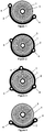
- the Figures 1 to 8 illustrate eight variants of spiral springs 1 whose outer end came from manufacture with a connecting member 2 to the frame of a timepiece.
- the rigidity of this connecting member 2 is substantially greater than that of the hairspring 1, typically 1000 times higher in the plane of the hairspring, and 10 times higher perpendicularly to the plane of the hairspring.
- the inner ends of these spiral springs are also manufactured with a fixing ferrule 3, intended to be driven, as usual, on the pivot shaft of a beam.
- the connecting member 2 extends angularly with respect to the axis of pivoting of the shaft on which the shell 3 is to be driven.
- this connecting member is able to provide the less a stable bearing surface to the spiral spring 1 as long as it is associated with a bearing surface at least partially complementary as will be seen later. These bearing surfaces are substantially parallel to the plane of the spiral spring 1.
- the connecting member 2 advantageously comprises two or even three positioning and fixing elements, consisting of openings 4 for the passage of fasteners, in particular pins or screws. These openings are preferably angularly distributed to allow to apply the connecting member 2 against the complementary bearing surface at several points of its bearing surface. In this way and within the limits of tolerances allowed, once the connecting member fixed to its complementary bearing surface, the spiral spring retains in the state of rest the three-dimensional integrity of its initial shape.
- the openings 4a may be non-circular, for example of elongate shape, to allow correction of small centering defects may come from tolerances allowed.
- the elongated opening 4a may be associated with an eccentric adjusting member, the angular displacement of which will make it possible to finely adjust the centering of the hairspring relative to the frame, by a rotation of the connecting member 2 by relative to the center of the opening 4, the clamping of the connecting member 2 occurring after the centering of the spiral spring 1.
- the fineness of the positioning is proportional to the spacing between the openings 4 and 4a.
- the eccentric adjustment member may also be associated with the circular opening 4, but this variant is less favorable for the adjustment since it implies that the two openings 4, 4a move under the effect of the adjusting member. .
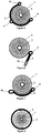
- the variant of the figure 8 relates to an annular connecting member 2, here associated with a spiral spring with two blades angularly offset by 180 °, wherein the connecting member 2 has no positioning and fixing element. Fixing such an annular connecting member 2 can be obtained for example as illustrated by the Figures 20 to 22 which will be described below.
- annular link 2 of the figure 8 is obviously also usable with a spiral spring with a single blade, as those of Figures 1 to 7 .
- annular connecting members 2 of the Figures 1-7 can also be used with spiral springs with multiple blades.
- connection member 2 is fixed directly to the balance bridge, or, advantageously, it is fixed to the balance bridge by an intermediate piece, pivotally mounted about the pivot axis of the balance shaft, which allows to adjust the landmark on the watch movement.
- the setting of the marker consists of bringing the center of the balance plate pin on the line connecting the respective pivot centers of the balance and the anchor, when the balance-sprung regulator member is in the equilibrium position.
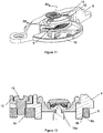
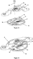
- FIGS 9 to 12 illustrate a first variant of a first embodiment, wherein the connecting member 2 comprises at least two positioning elements and corresponding bearing surfaces.
- the connecting member 2 comprises at least two positioning elements and corresponding bearing surfaces.
- a spiral spring 1 similar to that illustrated by the figure 1 .
- Two fixing pins 5 are intended to pass through the openings 4 of the connecting member 2 and to be driven into corresponding openings 6a formed in an intermediate piece 6, provided with an opening 6b concentric with the central axis of the ferrule 3 after assembling the elements of the figure 9 .
- the opening 6b of this intermediate piece 6 is intended to be fitted over a circular bearing surface of the balance bridge, coaxial with the axis of pivoting of the balance shaft, to allow the adjustment of the marker as will be seen later. .
- This intermediate piece 6 thus serves as angular positioning member of the sprung-balance regulator.
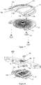
- the figure 10 shows the assembly step following the figure 9 .
- the angular positioning member 6 is pivotally mounted around the balance bridge 9, and is fixed thereto via two screws 13 passing through a clamping plate 12 on the one hand, two oblong cutouts 9a of the balance bridge 9 of FIG. secondly, to be screwed into two tapped holes 6c of the angular positioning member 6.
- the clamping plate 12 is here of arcuate shape and is mounted on the board of the balance bridge 9.
- the pivot shaft of the balance 10a and the balance 10b can be assembled to the hairspring before or after the mounting of the intermediate piece 6.
- the figure 11 shows the assembled state of this first variant.
- the adjustment of the mark of the balance spring-balance regulator member 10 can be effected by slightly loosening the two screws 13, then by pivoting the integral assembly consisting of the spring 1 whose inner end is integral with the balance shaft 10 a -spiral 10, the angular positioning member 6, and the clamping plate 12.
- the figure 12 shows a section of the figure 11 , allowing to see how the angular positioning member 6 is pivotally mounted via its opening 6b around a cylindrical surface 9b of the balance bridge 9.
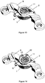
- the Figures 13 and 14 illustrate a second variant of the first embodiment.
- the spiral spring 1 used corresponds to that illustrated by the figure 1 . It comprises a connecting member 2 extending about 180 ° about the pivot axis of the balance shaft, whose ends are fixed to the angular positioning member 6 pivotally mounted under the balance bridge 9 around bearing 11 pivoting one of the ends of the balance shaft.
- the figure 13 shows this angular positioning member 6 and the figure 14 shows the same elements as the figure 13 but after attaching a wafer 12 to this angular positioning member 6 by two screws 13.
- the wafer 12 and the angular positioning member 6 are mounted frictionally around the bearing 11, making it possible to adjust the mark in the traditional manner, as with a standard piton door.
- FIGs 15 and 16 illustrate a third variant of the first embodiment in which the angular positioning member 6 carries a pin 14 which allows a temporary fixing of the sprung balance regulator member 10 in a bayonet attachment opening 9c in the board of the pendulum bridge 9, as illustrated by the figure 15 .
- a foil 15 is set up with one of its ends between the board of the pendulum bridge 9 and the scope of the pin 14, while its other end is located between the board of the bridge 9 and the head of a screw single-range 16 which is screwed in abutment against the angular positioning member 6, for generating a sufficient friction torque for holding the connecting member 2 while allowing easy adjustment of the setting benchmark of the spring balance regulator 10.
- FIGS 17 to 19 illustrate a fourth variant of the first embodiment, particularly suitable for mounting a double spiral whose outer ends of the blades are secured to a connecting member 2 in the form of a ring, in this case open ring .
- the figure 17 illustrates a first assembly step.
- the spiral 1 is here secured to the spiral support 17 by three pins 5 which pass through the openings 4 of the spiral 1 to be driven into the openings 17c of the intermediate part 17.
- the attachment points may be simple circular positioning holes 4 made in the ring that form
- the positioning holes 4 of the connecting member 2 could incorporate flexible arms (not shown) for a good positioning, or present an open contour like a split ferrule. with a certain elasticity, thus forming elastic arms so as to ensure a clamping around the pins 5.
- the figure 18 illustrates a second assembly step.
- the spiral support 17 provided with the spiral spring 1 is connected to the balance bridge 9 by the angular positioning member 6, by means of two screws 13 passing through openings 6d of the member 6 and screwed into the threaded holes 17a of the support 17.
- the good positioning of the assembly is achieved by exceeding the pins 5 which are housed in fitted openings 6e of the body 6.
- the figure 19 illustrates the complete assembly. It can be seen here that the angular positioning member 6 is provided with a ring 6b having a slot 6c which, by friction around the bearing 11 of the balance shaft, integral with the balance bridge 9, the angular positioning of the regulating organ and therefore easy adjustment of the marker.
- the clearance can be adjusted at the level of each fastener 17c to guarantee the most accurate hold possible without over-constraining the system and rendering it hyperstatic. .
- a possible choice to ensure a good assembly is to leave more play at the intermediate attachment point 17c ', which will then have a greater diameter than the others to absorb the various errors due to manufacturing tolerances of other components.
- An alternative is to define the sets of all attachment points according to the tolerances of the rigid part.
- the lower face of the spiral support 17 has a clearance 17e to avoid friction with the spiral spring.
- the arms 17d of the support 17 serve as a stop to the deformations of the spring 1 under the effect of an impact.
- FIG. 20 A second embodiment not forming part of the claimed invention is illustrated by the Figures 20 to 22 .
- This solution uses the spiral spring of the figure 8 but is also suitable for any other spiral spring provided with a similar connecting member 2. It consists in pinching axially the more rigid annular connecting member 2 between an intermediate fastening piece 7, provided with a positioning hole 7a ( figure 22 ) to receive the annular connecting member 2, and the pendulum bridge or an angular positioning member.
- This positioning wedge 7a makes it possible to set the reference point of the balance-sprung regulator member, when the inner end of the balance spring is assembled to the balance shaft.
- Two fastening screws 13 make it possible to tighten the annular connecting member 2 between the rocker bridge 9 and the intermediate fastener piece 7, the depth of the hole 7a formed in the intermediate fastening piece 7 being less than a few hundredths of a millimeter. to the thickness of the annular connecting member 2 ( figure 22 ).
- a third embodiment not forming part of the claimed invention consists in providing resilient arms 2a separating two parts of the connecting member 2, which allows, in the variant illustrated in FIGS. Figures 23 and 24 , clipping the annular connecting member 2 about pins 16 driven in the balance bridge 9, the centering being provided by two positioning elements 4b (centering cuts) formed in the connecting member 2.
- the surface of support extends over an arc of at least 60 °.
- a fourth embodiment not forming part of the claimed invention, close to the previous one, consists in providing, in addition to or instead of the elastic arms 2a, resilient arms 2c in the edge of the annular connecting member 2 ( Figures 25 and 26 ) to allow clipping of the ring in housings 17 provided for this purpose in the balance bridge 9.
- the setting of the marker can be performed by changing the angular position of the spiral, for example using tools that come s insert in passages 2d formed in the connecting member 2.
Landscapes
- Physics & Mathematics (AREA)
- General Physics & Mathematics (AREA)
- Engineering & Computer Science (AREA)
- Manufacturing & Machinery (AREA)
- Springs (AREA)
Claims (14)
- Uhrwerk oder Uhr umfassend ein Uhrwerk, wobei das Uhrwerk ein Organ zur Winkeleinstellung (6) und ein Regulierorgan mit Spiralfeder-Unruh (10) umfasst, welches eine Welle umfasst, die dazu vorgesehen ist, entlang einer Drehachse auf einem Gehäuse des Uhrwerks drehbar montiert zu werden, wobei das Regulierorgan so ausgebildet ist, dass die Spiralfeder (1) des genannten Regulierorgans (10) mindestens ein Blatt umfasst, welches in einer Ebene liegt, dessen inneres Ende dazu vorgesehen ist, an der genannte Drehwelle befestigt zu werden und dessen äußeres Ende einteilig mit einem Verbindungsorgan (2) an dem Organ zur Winkeleinstellung (6) des genannten Regulierorgans (10) an dem genannten Gehäuse (10) gefertigt ist, wobei die Steifigkeit dieses Verbindungsorgans (2) wesentlich größer ist als die des wenigstens einen Blattes,
dadurch gekennzeichnet, dass
das genannte Verbindungsorgan (2) einerseits und das Organ zur Winkeleinstellung (6) des genannten Regulierorgans (10) an dem genannten Gehäuse andererseits, beide jeweils Lageroberflächen aufweisen, die zumindest teilweise komplementär und im Wesentlichen parallel zu Ebene der Spiralfeder sind, wobei Befestigungsmittel (5) dazu dienen, diese komplementären Lageroberflächen zu verbinden, und dass das genannte Verbindungsorgan (2) mindestens zwei Positionierungs- und Befestigungsmittel (4) die winklig rings um die Drehachse herum angeordnet sind und mit den genannten Befestigungsmitteln (5) zusammenwirken. - Uhrwerk oder Uhr gemäß Anspruch 1, bei dem die genannten Lageroberflächen sich auf einen Winkelbereich von > 60° um die Drehachse herum erstrecken.
- Uhrwerk oder Uhr gemäß Anspruch 1 oder 2, bei dem die Lageroberfläche durchgehend ausgebildet sind.
- Uhrwerk oder Uhr gemäß einem der vorangehenden Ansprüche, bei dem eine einzelne Oberfläche sich auf mehr als 60° rings um die Drehachse der Welle herum erstreckt, sogar auf mehr als 120° rings um die Drehachse der Welle herum, sogar auf 180° oder mehr rings um die Drehachse der Welle herum.
- Uhrwerk oder Uhr gemäß Anspruch 1 oder 2, bei dem mindestens eine der Lageroberflächen diskontinuierlich ausgebildet ist.
- Uhrwerk oder Uhr gemäß dem vorangehenden Anspruch, bei dem zwei Elemente einer Oberfläche mit mehr als 60° voneinander beabstandet rings um die Drehachse der Welle herum angeordnet sind, sogar mit mehr als 120° voneinander beabstandet rings um die Drehachse der Welle herum, sogar mit 180° voneinander beabstandet rings um die Drehachse der Welle herum und/oder bei dem die beiden Elemente sich auf mehr als 10° erstrecken, sogar auf mehr als 20° rings um die Drehachse der Welle herum.
- Uhrwerk oder Uhr gemäß einem der vorangehenden Ansprüche, bei dem das Profil und die winklige Erstreckung der genannten, jeweiligen, zumindest teilweise komplementären Lageroberflächen im Verhältnis zur Drehachse der genannten Welle so geformt und dimensioniert ist, dass sie im Ruhezustand die dreidimensionale Integrität der ursprünglichen Form der Spiralfeder (1) erhalten, nach der Befestigung der genannten, komplementären Lageroberflächen untereinander.
- Uhrwerk oder Uhr gemäß einem der vorangehenden Ansprüche, bei dem der Winkelabstand zwischen den genannten Positions- und Befestigungselementen zwischen 60° und 180° liegt.
- Uhrwerk oder Uhr gemäß einem der vorangehenden Ansprüche, bei dem das Organ zur Winkeleinstellung (6) drehbar um das Drehlager (11) der Unruhwelle herum an einer Unruhbrücke (9) montiert ist.
- Uhrwerk oder Uhr gemäß einem der vorangehenden Ansprüche, bei dem das genannte Verbindungsorgan (2) ein ringförmiges Organ ist.
- Uhrwerk oder Uhr gemäß dem vorangehenden Anspruch, bei dem das ringförmige Verbindungsorgan (2) zwischen einem Befestigungszwischenteil (7), versehen mit einer Positionierungsvertiefung (7a) zur Aufnahme des ringförmigen Verbindungsorgans (2), und der inneren Seite der Unruhbrücke angeordnet ist, wobei Klemmmittel (8) vorgesehen sind, um das ringförmige Verbindungsorgan (2) zwischen dem Zwischenteil (7) und der Unruhbrücke (9) zu verklemmen.
- Uhrwerk oder Uhr gemäß einem der Ansprüche 1 bis 10, bei dem das Organ zur Winkeleinstellung (6) einen Sperrstift mit Auflagefläche (14) trägt, um in eine Öffnung mit Bajonettverschluss (9a) der Unruhbrücke einzugreifen, wobei ein Flitter (15) vorgesehen ist zwischen der Platte der Unruhbrücke (9) und einerseits der Auflagefläche des Sperrstifts (14), andererseits einer Schraube mit Auflagefläche (16), die bis zum Anliegen gegen das Verbindungsorgan (2) geschraubt ist, wobei der Flitter eine Reibpaarung zum Halten des Verbindungsorgans (2) erzeugt und gleichzeitig eine Justierung des Regulierorgans erlaubt.
- Uhrwerk oder Uhr gemäß einem der Ansprüche 1 bis 10, bei dem die Spiralfeder (1) zwei Blätter umfasst, deren äußere Enden jeweils mit dem Verbindungsorgan (2) verbunden sind, wobei die Mittel zur Befestigung der genannten Spiralfeder am Organ zur Winkeleinstellung (6) ein steiferes Spiralfeder-Trägerelement (17) umfassen, welches an dem Verbindungsorgan mit Hilfe einer Schraubverbindung (18) befestigt ist.
- Uhrwerk oder Uhr gemäß einem der vorangehenden Ansprüche, bei dem das Organ zur Winkeleinstellung (6) einen Spaltring (6b) umfasst für seine reibschlüssige Verbindung um das Lager (11) der Unruhwelle herum, das mit der Unruhbrücke (9) verbunden ist.
Priority Applications (1)
| Application Number | Priority Date | Filing Date | Title |
|---|---|---|---|
| EP11405331.7A EP2437126B1 (de) | 2010-10-04 | 2011-09-27 | Regulierorgan mit Spiralunruh |
Applications Claiming Priority (2)
| Application Number | Priority Date | Filing Date | Title |
|---|---|---|---|
| EP10405183 | 2010-10-04 | ||
| EP11405331.7A EP2437126B1 (de) | 2010-10-04 | 2011-09-27 | Regulierorgan mit Spiralunruh |
Publications (2)
| Publication Number | Publication Date |
|---|---|
| EP2437126A1 EP2437126A1 (de) | 2012-04-04 |
| EP2437126B1 true EP2437126B1 (de) | 2019-03-27 |
Family
ID=43707756
Family Applications (1)
| Application Number | Title | Priority Date | Filing Date |
|---|---|---|---|
| EP11405331.7A Active EP2437126B1 (de) | 2010-10-04 | 2011-09-27 | Regulierorgan mit Spiralunruh |
Country Status (5)
| Country | Link |
|---|---|
| US (1) | US8672535B2 (de) |
| EP (1) | EP2437126B1 (de) |
| JP (1) | JP5886585B2 (de) |
| CN (1) | CN102540849B (de) |
| CH (1) | CH703935B1 (de) |
Cited By (1)
| Publication number | Priority date | Publication date | Assignee | Title |
|---|---|---|---|---|
| EP4099101A1 (de) | 2021-06-03 | 2022-12-07 | Rolex Sa | Vorrichtung zum einbau eines uhr-oszillators |
Families Citing this family (17)
| Publication number | Priority date | Publication date | Assignee | Title |
|---|---|---|---|---|
| CH707815B1 (fr) * | 2013-03-19 | 2017-05-31 | Nivarox Far Sa | Sous-ensemble de mécanisme d'échappement d'horlogerie comportant un ressort-spiral. |
| CH707811A2 (fr) * | 2013-03-19 | 2014-09-30 | Nivarox Sa | Composant monobloc indémontable d'horlogerie. |
| EP2781970B1 (de) * | 2013-03-19 | 2016-03-16 | Nivarox-FAR S.A. | Spiralfederregulierungsmechanismus einer Uhr |
| CN104133362B (zh) * | 2013-05-01 | 2021-05-18 | 劳力士有限公司 | 钟表振荡器的摆锤的减震体 |
| EP2863274B1 (de) | 2013-10-18 | 2017-03-15 | Omega SA | Flexible elastische Zeiger |
| CH710188A2 (fr) * | 2014-09-26 | 2016-03-31 | Eta Sa Manufacture Horlogère Suisse | Résonateur d'horlogerie paraxial et isochrone. |
| JP6710041B2 (ja) | 2014-11-27 | 2020-06-17 | ロレックス・ソシエテ・アノニムRolex Sa | ヒゲゼンマイ固定システム |
| EP3147728A1 (de) * | 2015-09-24 | 2017-03-29 | Harry Winston SA | Mechanismus zum positionieren eines zahnrads in einem uhrwerk |
| CH713288A1 (fr) | 2016-12-23 | 2018-06-29 | Sa De La Manufacture Dhorlogerie Audemars Piguet & Cie | Composant monolithique flexible pour pièce d'horlogerie. |
| JP6355282B1 (ja) * | 2017-03-13 | 2018-07-11 | セイコーインスツル株式会社 | 携帯機器用部品の固定構造 |
| EP3812846B1 (de) * | 2019-10-24 | 2025-11-26 | ETA SA Manufacture Horlogère Suisse | Zusammenbau- und ausrichtungsvorrichtung insbesondere für einen resonatormechanismus eines uhrwerks |
| EP3859451A1 (de) * | 2020-01-29 | 2021-08-04 | ETA SA Manufacture Horlogère Suisse | Vorrichtung zur einstellung des lagerspiels |
| JP6766284B1 (ja) * | 2020-03-02 | 2020-10-07 | セイコーウオッチ株式会社 | 渦巻ばね、トルク発生装置、時計用ムーブメントおよび時計 |
| EP4006649A1 (de) * | 2020-11-27 | 2022-06-01 | ETA SA Manufacture Horlogère Suisse | Befestigungsvorrichtung zur einstellung des unruhspiels |
| CN117501187A (zh) * | 2021-06-03 | 2024-02-02 | 劳力士有限公司 | 用于钟表机芯部件的制造方法 |
| EP4286960B1 (de) * | 2022-06-02 | 2026-03-25 | ETA SA Manufacture Horlogère Suisse | Regulierorgan für uhr, das mit einer rückervorrichtung ausgestattet ist |
| EP4407382A1 (de) | 2023-01-25 | 2024-07-31 | Rolex Sa | Spiralfeder für uhrwerk |
Family Cites Families (16)
| Publication number | Priority date | Publication date | Assignee | Title |
|---|---|---|---|---|
| US1023140A (en) * | 1908-12-11 | 1912-04-16 | Frederic Ecaubert | Escapement-regulator. |
| US3154912A (en) * | 1963-01-22 | 1964-11-03 | Pinkas David | Means for mounting and regulating the outer end of a spiral spring |
| JPS4711179Y1 (de) * | 1968-10-04 | 1972-04-25 | ||
| US3943701A (en) * | 1975-01-08 | 1976-03-16 | Timex Corporation | Regulator and balance bridge arrangement for a horological device |
| JPS5244047Y1 (de) * | 1976-01-08 | 1977-10-06 | ||
| US6612734B1 (en) * | 1999-07-29 | 2003-09-02 | Seiko Instruments Inc. | Mechanical timepiece with stud adjustment mechanism |
| EP1515200A1 (de) | 2003-09-10 | 2005-03-16 | Patek Philippe S.A. | Spiralfeder für Uhren |
| DE60314143T2 (de) * | 2003-10-01 | 2008-01-31 | Asulab S.A. | Uhr mit einem mechanischen Uhrwerk, das mit einem elektronischen Regulator gekoppelt ist |
| DE10345918A1 (de) * | 2003-10-02 | 2005-05-12 | Lange Uhren Gmbh | Schwingsystem |
| CH697208A5 (fr) * | 2004-04-08 | 2008-06-25 | Coredem Sa | Ensemble balancier-spiral pour mouvement d'horlogerie mécanique. |
| GB0509886D0 (en) * | 2005-05-14 | 2005-06-22 | Levingston Gideon R | Balance wheel mass and regulating element assembly and balance wheel and balance spring manufacturing processes for horolongical oscillator mechanisms |
| WO2006123095A2 (en) * | 2005-05-14 | 2006-11-23 | Gideon Levingston | Balance spring, regulated balance wheel assembly and methods of manufacture thereof |
| CH699746B1 (fr) * | 2005-12-14 | 2010-04-30 | Patek Philippe Sa Geneve | Dispositif mécanique de mise au repère de l'échappement d'un organe réglant. |
| DE102006052245A1 (de) | 2006-11-03 | 2008-05-08 | Lange Uhren Gmbh | Schwingsystem für eine Uhr |
| EP2151722B8 (de) * | 2008-07-29 | 2021-03-31 | Rolex Sa | Spiralfeder für Spiralfeder-Unruh-Resonator |
| EP2394202B1 (de) * | 2009-02-06 | 2016-09-07 | DAMASKO GmbH | Mechanisches schwingsystem für uhren sowie funktionselement für uhren |
-
2011
- 2011-09-27 EP EP11405331.7A patent/EP2437126B1/de active Active
- 2011-09-27 CH CH01586/11A patent/CH703935B1/en unknown
- 2011-09-29 US US13/248,423 patent/US8672535B2/en active Active
- 2011-09-30 CN CN201110348467.1A patent/CN102540849B/zh active Active
- 2011-10-03 JP JP2011218906A patent/JP5886585B2/ja active Active
Non-Patent Citations (1)
| Title |
|---|
| None * |
Cited By (3)
| Publication number | Priority date | Publication date | Assignee | Title |
|---|---|---|---|---|
| EP4099101A1 (de) | 2021-06-03 | 2022-12-07 | Rolex Sa | Vorrichtung zum einbau eines uhr-oszillators |
| EP4567529A2 (de) | 2021-06-03 | 2025-06-11 | Rolex Sa | Vorrichtung zur montage eines uhrwerksoszillators |
| EP4567529A3 (de) * | 2021-06-03 | 2025-09-24 | Rolex Sa | Vorrichtung zur montage eines uhrwerksoszillators |
Also Published As
| Publication number | Publication date |
|---|---|
| JP5886585B2 (ja) | 2016-03-16 |
| CH703935A2 (fr) | 2012-04-13 |
| EP2437126A1 (de) | 2012-04-04 |
| CN102540849B (zh) | 2015-10-07 |
| CN102540849A (zh) | 2012-07-04 |
| JP2012078358A (ja) | 2012-04-19 |
| US20120082010A1 (en) | 2012-04-05 |
| CH703935B1 (en) | 2017-04-13 |
| US8672535B2 (en) | 2014-03-18 |
Similar Documents
| Publication | Publication Date | Title |
|---|---|---|
| EP2437126B1 (de) | Regulierorgan mit Spiralunruh | |
| EP2799937B1 (de) | Dämpfungskörper eines Unruh-Oszillators einer Uhr | |
| EP4009115A1 (de) | Spiralfeder für resonatormechanismus eines uhrwerks, der mit mitteln zum ausgleichen der starrheit ausgestattet ist | |
| EP2804055B1 (de) | Einheit aus einem Spiralklötzchen und einem Spiralklötzchenträger | |
| EP3172626B1 (de) | Drehzapfen mit einem blatt | |
| EP2887154A1 (de) | Befestigungsmechanismus eines Spiralklötzchen an eine Unruhbrücke, und Reguliervorrichtung mit Unruh-Spiralfeder, die einen solchen Mechanismus umfasst | |
| EP3502788A1 (de) | Vorrichtung zur selbstregulierung der aktiven länge einer spirale | |
| EP2743781B1 (de) | Montagevorrichtung zum Verriegeln eines Verbundsystems | |
| CH705605A2 (fr) | Dispositif de réglage de la longueur active d'un spiral. | |
| EP3839651A1 (de) | Mechanischer oszillator einer uhr mit flexibler führung | |
| CH701075B1 (fr) | Ensemble formé d'une roue et de son axe et roue pour un tel ensemble. | |
| WO2017207880A1 (fr) | Objet décoratif, tel qu'un bijou, comprenant un corps et un élément décoratif fixé de manière réversible au corps | |
| EP3037896B1 (de) | Demontierbarer spiralklötzchenträger | |
| EP3432081B1 (de) | Uhreneinheit | |
| EP3432082B1 (de) | Regulierorgan | |
| EP3037895B1 (de) | Ausbaubarer Spiralklötzchenträger | |
| EP4407382A1 (de) | Spiralfeder für uhrwerk | |
| CH709070A2 (fr) | Dispositif régulateur à balancier-spiral comprenant un mécanisme de fixation d'un piton à un pont de balancier. | |
| CH713999A1 (fr) | Composant horloger destiné à être fixé sur un axe. | |
| EP4492156A1 (de) | Uhrvorrichtung | |
| CH716553B1 (fr) | Mécanisme horloger de génération d'une friction limitant le couple transmis entre deux pièces rotatitves et ressort de friction pour un tel mécanisme. | |
| EP4386486A1 (de) | Spiralfeder für resonatormechanismus einer uhr mit mitteln zur einstellung der flexibilität und zugehörige materialien | |
| EP4296790A1 (de) | Spiralklötzchenträgervorrichtung | |
| WO2025017405A1 (fr) | Anneau-ressort pour boîte de montre et procédé de fabrication d'un anneau-ressort | |
| EP4327163A1 (de) | Anordnung zur ausstattung eines uhrenmechanismus und mindestens ein elastisches element und mindestens eine erste und eine zweite uhrkomponente umfassend |
Legal Events
| Date | Code | Title | Description |
|---|---|---|---|
| PUAI | Public reference made under article 153(3) epc to a published international application that has entered the european phase |
Free format text: ORIGINAL CODE: 0009012 |
|
| AK | Designated contracting states |
Kind code of ref document: A1 Designated state(s): AL AT BE BG CH CY CZ DE DK EE ES FI FR GB GR HR HU IE IS IT LI LT LU LV MC MK MT NL NO PL PT RO RS SE SI SK SM TR |
|
| AX | Request for extension of the european patent |
Extension state: BA ME |
|
| 17P | Request for examination filed |
Effective date: 20121004 |
|
| 17Q | First examination report despatched |
Effective date: 20130212 |
|
| GRAP | Despatch of communication of intention to grant a patent |
Free format text: ORIGINAL CODE: EPIDOSNIGR1 |
|
| STAA | Information on the status of an ep patent application or granted ep patent |
Free format text: STATUS: GRANT OF PATENT IS INTENDED |
|
| INTG | Intention to grant announced |
Effective date: 20170623 |
|
| GRAJ | Information related to disapproval of communication of intention to grant by the applicant or resumption of examination proceedings by the epo deleted |
Free format text: ORIGINAL CODE: EPIDOSDIGR1 |
|
| GRAP | Despatch of communication of intention to grant a patent |
Free format text: ORIGINAL CODE: EPIDOSNIGR1 |
|
| GRAJ | Information related to disapproval of communication of intention to grant by the applicant or resumption of examination proceedings by the epo deleted |
Free format text: ORIGINAL CODE: EPIDOSDIGR1 |
|
| STAA | Information on the status of an ep patent application or granted ep patent |
Free format text: STATUS: EXAMINATION IS IN PROGRESS |
|
| INTG | Intention to grant announced |
Effective date: 20170911 |
|
| INTC | Intention to grant announced (deleted) | ||
| GRAP | Despatch of communication of intention to grant a patent |
Free format text: ORIGINAL CODE: EPIDOSNIGR1 |
|
| STAA | Information on the status of an ep patent application or granted ep patent |
Free format text: STATUS: GRANT OF PATENT IS INTENDED |
|
| INTG | Intention to grant announced |
Effective date: 20171117 |
|
| INTG | Intention to grant announced |
Effective date: 20171117 |
|
| GRAJ | Information related to disapproval of communication of intention to grant by the applicant or resumption of examination proceedings by the epo deleted |
Free format text: ORIGINAL CODE: EPIDOSDIGR1 |
|
| GRAP | Despatch of communication of intention to grant a patent |
Free format text: ORIGINAL CODE: EPIDOSNIGR1 |
|
| GRAJ | Information related to disapproval of communication of intention to grant by the applicant or resumption of examination proceedings by the epo deleted |
Free format text: ORIGINAL CODE: EPIDOSDIGR1 |
|
| GRAJ | Information related to disapproval of communication of intention to grant by the applicant or resumption of examination proceedings by the epo deleted |
Free format text: ORIGINAL CODE: EPIDOSDIGR1 |
|
| GRAP | Despatch of communication of intention to grant a patent |
Free format text: ORIGINAL CODE: EPIDOSNIGR1 |
|
| GRAP | Despatch of communication of intention to grant a patent |
Free format text: ORIGINAL CODE: EPIDOSNIGR1 |
|
| GRAJ | Information related to disapproval of communication of intention to grant by the applicant or resumption of examination proceedings by the epo deleted |
Free format text: ORIGINAL CODE: EPIDOSDIGR1 |
|
| GRAP | Despatch of communication of intention to grant a patent |
Free format text: ORIGINAL CODE: EPIDOSNIGR1 |
|
| GRAJ | Information related to disapproval of communication of intention to grant by the applicant or resumption of examination proceedings by the epo deleted |
Free format text: ORIGINAL CODE: EPIDOSDIGR1 |
|
| INTG | Intention to grant announced |
Effective date: 20180123 |
|
| GRAP | Despatch of communication of intention to grant a patent |
Free format text: ORIGINAL CODE: EPIDOSNIGR1 |
|
| INTG | Intention to grant announced |
Effective date: 20180206 |
|
| INTG | Intention to grant announced |
Effective date: 20180216 |
|
| INTG | Intention to grant announced |
Effective date: 20180226 |
|
| INTG | Intention to grant announced |
Effective date: 20180305 |
|
| GRAJ | Information related to disapproval of communication of intention to grant by the applicant or resumption of examination proceedings by the epo deleted |
Free format text: ORIGINAL CODE: EPIDOSDIGR1 |
|
| STAA | Information on the status of an ep patent application or granted ep patent |
Free format text: STATUS: EXAMINATION IS IN PROGRESS |
|
| INTC | Intention to grant announced (deleted) | ||
| GRAP | Despatch of communication of intention to grant a patent |
Free format text: ORIGINAL CODE: EPIDOSNIGR1 |
|
| STAA | Information on the status of an ep patent application or granted ep patent |
Free format text: STATUS: GRANT OF PATENT IS INTENDED |
|
| INTG | Intention to grant announced |
Effective date: 20180917 |
|
| GRAJ | Information related to disapproval of communication of intention to grant by the applicant or resumption of examination proceedings by the epo deleted |
Free format text: ORIGINAL CODE: EPIDOSDIGR1 |
|
| STAA | Information on the status of an ep patent application or granted ep patent |
Free format text: STATUS: EXAMINATION IS IN PROGRESS |
|
| GRAR | Information related to intention to grant a patent recorded |
Free format text: ORIGINAL CODE: EPIDOSNIGR71 |
|
| GRAS | Grant fee paid |
Free format text: ORIGINAL CODE: EPIDOSNIGR3 |
|
| STAA | Information on the status of an ep patent application or granted ep patent |
Free format text: STATUS: GRANT OF PATENT IS INTENDED |
|
| GRAA | (expected) grant |
Free format text: ORIGINAL CODE: 0009210 |
|
| STAA | Information on the status of an ep patent application or granted ep patent |
Free format text: STATUS: THE PATENT HAS BEEN GRANTED |
|
| INTC | Intention to grant announced (deleted) | ||
| INTG | Intention to grant announced |
Effective date: 20190214 |
|
| AK | Designated contracting states |
Kind code of ref document: B1 Designated state(s): AL AT BE BG CH CY CZ DE DK EE ES FI FR GB GR HR HU IE IS IT LI LT LU LV MC MK MT NL NO PL PT RO RS SE SI SK SM TR |
|
| REG | Reference to a national code |
Ref country code: GB Ref legal event code: FG4D Free format text: NOT ENGLISH |
|
| REG | Reference to a national code |
Ref country code: CH Ref legal event code: EP |
|
| REG | Reference to a national code |
Ref country code: AT Ref legal event code: REF Ref document number: 1113801 Country of ref document: AT Kind code of ref document: T Effective date: 20190415 |
|
| REG | Reference to a national code |
Ref country code: IE Ref legal event code: FG4D Free format text: LANGUAGE OF EP DOCUMENT: FRENCH |
|
| REG | Reference to a national code |
Ref country code: DE Ref legal event code: R096 Ref document number: 602011057487 Country of ref document: DE |
|
| REG | Reference to a national code |
Ref country code: CH Ref legal event code: NV Representative=s name: MOINAS AND SAVOYE SA, CH |
|
| PG25 | Lapsed in a contracting state [announced via postgrant information from national office to epo] |
Ref country code: FI Free format text: LAPSE BECAUSE OF FAILURE TO SUBMIT A TRANSLATION OF THE DESCRIPTION OR TO PAY THE FEE WITHIN THE PRESCRIBED TIME-LIMIT Effective date: 20190327 Ref country code: NO Free format text: LAPSE BECAUSE OF FAILURE TO SUBMIT A TRANSLATION OF THE DESCRIPTION OR TO PAY THE FEE WITHIN THE PRESCRIBED TIME-LIMIT Effective date: 20190627 Ref country code: LT Free format text: LAPSE BECAUSE OF FAILURE TO SUBMIT A TRANSLATION OF THE DESCRIPTION OR TO PAY THE FEE WITHIN THE PRESCRIBED TIME-LIMIT Effective date: 20190327 Ref country code: SE Free format text: LAPSE BECAUSE OF FAILURE TO SUBMIT A TRANSLATION OF THE DESCRIPTION OR TO PAY THE FEE WITHIN THE PRESCRIBED TIME-LIMIT Effective date: 20190327 |
|
| REG | Reference to a national code |
Ref country code: NL Ref legal event code: MP Effective date: 20190327 |
|
| PG25 | Lapsed in a contracting state [announced via postgrant information from national office to epo] |
Ref country code: RS Free format text: LAPSE BECAUSE OF FAILURE TO SUBMIT A TRANSLATION OF THE DESCRIPTION OR TO PAY THE FEE WITHIN THE PRESCRIBED TIME-LIMIT Effective date: 20190327 Ref country code: NL Free format text: LAPSE BECAUSE OF FAILURE TO SUBMIT A TRANSLATION OF THE DESCRIPTION OR TO PAY THE FEE WITHIN THE PRESCRIBED TIME-LIMIT Effective date: 20190327 Ref country code: BG Free format text: LAPSE BECAUSE OF FAILURE TO SUBMIT A TRANSLATION OF THE DESCRIPTION OR TO PAY THE FEE WITHIN THE PRESCRIBED TIME-LIMIT Effective date: 20190627 Ref country code: HR Free format text: LAPSE BECAUSE OF FAILURE TO SUBMIT A TRANSLATION OF THE DESCRIPTION OR TO PAY THE FEE WITHIN THE PRESCRIBED TIME-LIMIT Effective date: 20190327 Ref country code: GR Free format text: LAPSE BECAUSE OF FAILURE TO SUBMIT A TRANSLATION OF THE DESCRIPTION OR TO PAY THE FEE WITHIN THE PRESCRIBED TIME-LIMIT Effective date: 20190628 Ref country code: LV Free format text: LAPSE BECAUSE OF FAILURE TO SUBMIT A TRANSLATION OF THE DESCRIPTION OR TO PAY THE FEE WITHIN THE PRESCRIBED TIME-LIMIT Effective date: 20190327 |
|
| REG | Reference to a national code |
Ref country code: AT Ref legal event code: MK05 Ref document number: 1113801 Country of ref document: AT Kind code of ref document: T Effective date: 20190327 |
|
| PG25 | Lapsed in a contracting state [announced via postgrant information from national office to epo] |
Ref country code: EE Free format text: LAPSE BECAUSE OF FAILURE TO SUBMIT A TRANSLATION OF THE DESCRIPTION OR TO PAY THE FEE WITHIN THE PRESCRIBED TIME-LIMIT Effective date: 20190327 Ref country code: AL Free format text: LAPSE BECAUSE OF FAILURE TO SUBMIT A TRANSLATION OF THE DESCRIPTION OR TO PAY THE FEE WITHIN THE PRESCRIBED TIME-LIMIT Effective date: 20190327 Ref country code: PT Free format text: LAPSE BECAUSE OF FAILURE TO SUBMIT A TRANSLATION OF THE DESCRIPTION OR TO PAY THE FEE WITHIN THE PRESCRIBED TIME-LIMIT Effective date: 20190727 Ref country code: IT Free format text: LAPSE BECAUSE OF FAILURE TO SUBMIT A TRANSLATION OF THE DESCRIPTION OR TO PAY THE FEE WITHIN THE PRESCRIBED TIME-LIMIT Effective date: 20190327 Ref country code: RO Free format text: LAPSE BECAUSE OF FAILURE TO SUBMIT A TRANSLATION OF THE DESCRIPTION OR TO PAY THE FEE WITHIN THE PRESCRIBED TIME-LIMIT Effective date: 20190327 Ref country code: CZ Free format text: LAPSE BECAUSE OF FAILURE TO SUBMIT A TRANSLATION OF THE DESCRIPTION OR TO PAY THE FEE WITHIN THE PRESCRIBED TIME-LIMIT Effective date: 20190327 Ref country code: SK Free format text: LAPSE BECAUSE OF FAILURE TO SUBMIT A TRANSLATION OF THE DESCRIPTION OR TO PAY THE FEE WITHIN THE PRESCRIBED TIME-LIMIT Effective date: 20190327 Ref country code: ES Free format text: LAPSE BECAUSE OF FAILURE TO SUBMIT A TRANSLATION OF THE DESCRIPTION OR TO PAY THE FEE WITHIN THE PRESCRIBED TIME-LIMIT Effective date: 20190327 |
|
| PG25 | Lapsed in a contracting state [announced via postgrant information from national office to epo] |
Ref country code: SM Free format text: LAPSE BECAUSE OF FAILURE TO SUBMIT A TRANSLATION OF THE DESCRIPTION OR TO PAY THE FEE WITHIN THE PRESCRIBED TIME-LIMIT Effective date: 20190327 Ref country code: PL Free format text: LAPSE BECAUSE OF FAILURE TO SUBMIT A TRANSLATION OF THE DESCRIPTION OR TO PAY THE FEE WITHIN THE PRESCRIBED TIME-LIMIT Effective date: 20190327 |
|
| PG25 | Lapsed in a contracting state [announced via postgrant information from national office to epo] |
Ref country code: AT Free format text: LAPSE BECAUSE OF FAILURE TO SUBMIT A TRANSLATION OF THE DESCRIPTION OR TO PAY THE FEE WITHIN THE PRESCRIBED TIME-LIMIT Effective date: 20190327 Ref country code: IS Free format text: LAPSE BECAUSE OF FAILURE TO SUBMIT A TRANSLATION OF THE DESCRIPTION OR TO PAY THE FEE WITHIN THE PRESCRIBED TIME-LIMIT Effective date: 20190727 |
|
| REG | Reference to a national code |
Ref country code: DE Ref legal event code: R097 Ref document number: 602011057487 Country of ref document: DE |
|
| PG25 | Lapsed in a contracting state [announced via postgrant information from national office to epo] |
Ref country code: DK Free format text: LAPSE BECAUSE OF FAILURE TO SUBMIT A TRANSLATION OF THE DESCRIPTION OR TO PAY THE FEE WITHIN THE PRESCRIBED TIME-LIMIT Effective date: 20190327 |
|
| PLBE | No opposition filed within time limit |
Free format text: ORIGINAL CODE: 0009261 |
|
| STAA | Information on the status of an ep patent application or granted ep patent |
Free format text: STATUS: NO OPPOSITION FILED WITHIN TIME LIMIT |
|
| PG25 | Lapsed in a contracting state [announced via postgrant information from national office to epo] |
Ref country code: SI Free format text: LAPSE BECAUSE OF FAILURE TO SUBMIT A TRANSLATION OF THE DESCRIPTION OR TO PAY THE FEE WITHIN THE PRESCRIBED TIME-LIMIT Effective date: 20190327 |
|
| 26N | No opposition filed |
Effective date: 20200103 |
|
| PG25 | Lapsed in a contracting state [announced via postgrant information from national office to epo] |
Ref country code: TR Free format text: LAPSE BECAUSE OF FAILURE TO SUBMIT A TRANSLATION OF THE DESCRIPTION OR TO PAY THE FEE WITHIN THE PRESCRIBED TIME-LIMIT Effective date: 20190327 |
|
| PG25 | Lapsed in a contracting state [announced via postgrant information from national office to epo] |
Ref country code: MC Free format text: LAPSE BECAUSE OF FAILURE TO SUBMIT A TRANSLATION OF THE DESCRIPTION OR TO PAY THE FEE WITHIN THE PRESCRIBED TIME-LIMIT Effective date: 20190327 |
|
| PG25 | Lapsed in a contracting state [announced via postgrant information from national office to epo] |
Ref country code: LU Free format text: LAPSE BECAUSE OF NON-PAYMENT OF DUE FEES Effective date: 20190927 Ref country code: IE Free format text: LAPSE BECAUSE OF NON-PAYMENT OF DUE FEES Effective date: 20190927 |
|
| REG | Reference to a national code |
Ref country code: BE Ref legal event code: MM Effective date: 20190930 |
|
| PG25 | Lapsed in a contracting state [announced via postgrant information from national office to epo] |
Ref country code: BE Free format text: LAPSE BECAUSE OF NON-PAYMENT OF DUE FEES Effective date: 20190930 |
|
| PG25 | Lapsed in a contracting state [announced via postgrant information from national office to epo] |
Ref country code: CY Free format text: LAPSE BECAUSE OF FAILURE TO SUBMIT A TRANSLATION OF THE DESCRIPTION OR TO PAY THE FEE WITHIN THE PRESCRIBED TIME-LIMIT Effective date: 20190327 |
|
| PG25 | Lapsed in a contracting state [announced via postgrant information from national office to epo] |
Ref country code: MT Free format text: LAPSE BECAUSE OF FAILURE TO SUBMIT A TRANSLATION OF THE DESCRIPTION OR TO PAY THE FEE WITHIN THE PRESCRIBED TIME-LIMIT Effective date: 20190327 Ref country code: HU Free format text: LAPSE BECAUSE OF FAILURE TO SUBMIT A TRANSLATION OF THE DESCRIPTION OR TO PAY THE FEE WITHIN THE PRESCRIBED TIME-LIMIT; INVALID AB INITIO Effective date: 20110927 |
|
| PG25 | Lapsed in a contracting state [announced via postgrant information from national office to epo] |
Ref country code: MK Free format text: LAPSE BECAUSE OF FAILURE TO SUBMIT A TRANSLATION OF THE DESCRIPTION OR TO PAY THE FEE WITHIN THE PRESCRIBED TIME-LIMIT Effective date: 20190327 |
|
| P01 | Opt-out of the competence of the unified patent court (upc) registered |
Effective date: 20230528 |
|
| REG | Reference to a national code |
Ref country code: CH Ref legal event code: U11 Free format text: ST27 STATUS EVENT CODE: U-0-0-U10-U11 (AS PROVIDED BY THE NATIONAL OFFICE) Effective date: 20251001 |
|
| PGFP | Annual fee paid to national office [announced via postgrant information from national office to epo] |
Ref country code: DE Payment date: 20250916 Year of fee payment: 15 |
|
| PGFP | Annual fee paid to national office [announced via postgrant information from national office to epo] |
Ref country code: GB Payment date: 20250919 Year of fee payment: 15 |
|
| PGFP | Annual fee paid to national office [announced via postgrant information from national office to epo] |
Ref country code: FR Payment date: 20250929 Year of fee payment: 15 |
|
| PGFP | Annual fee paid to national office [announced via postgrant information from national office to epo] |
Ref country code: CH Payment date: 20251001 Year of fee payment: 15 |