EP3001256B2 - Échappement à ancre - Google Patents
Échappement à ancre Download PDFInfo
- Publication number
- EP3001256B2 EP3001256B2 EP14185997.5A EP14185997A EP3001256B2 EP 3001256 B2 EP3001256 B2 EP 3001256B2 EP 14185997 A EP14185997 A EP 14185997A EP 3001256 B2 EP3001256 B2 EP 3001256B2
- Authority
- EP
- European Patent Office
- Prior art keywords
- pallet
- stones
- teeth
- escapement
- wheel
- Prior art date
- Legal status (The legal status is an assumption and is not a legal conclusion. Google has not performed a legal analysis and makes no representation as to the accuracy of the status listed.)
- Active
Links
- 239000010432 diamond Substances 0.000 claims description 33
- 229910003460 diamond Inorganic materials 0.000 claims description 33
- 239000000463 material Substances 0.000 claims description 25
- 239000004575 stone Substances 0.000 claims description 18
- XUIMIQQOPSSXEZ-UHFFFAOYSA-N Silicon Chemical compound [Si] XUIMIQQOPSSXEZ-UHFFFAOYSA-N 0.000 claims description 12
- 239000010703 silicon Substances 0.000 claims description 12
- 229910052710 silicon Inorganic materials 0.000 claims description 12
- 238000000576 coating method Methods 0.000 claims description 10
- 239000011248 coating agent Substances 0.000 claims description 9
- VYPSYNLAJGMNEJ-UHFFFAOYSA-N Silicium dioxide Chemical compound O=[Si]=O VYPSYNLAJGMNEJ-UHFFFAOYSA-N 0.000 claims description 5
- 239000010979 ruby Substances 0.000 claims description 5
- 229910001750 ruby Inorganic materials 0.000 claims description 5
- 229910052799 carbon Inorganic materials 0.000 claims description 3
- OKTJSMMVPCPJKN-UHFFFAOYSA-N Carbon Chemical compound [C] OKTJSMMVPCPJKN-UHFFFAOYSA-N 0.000 claims description 2
- 229910052581 Si3N4 Inorganic materials 0.000 claims description 2
- 229910052594 sapphire Inorganic materials 0.000 claims description 2
- 239000010980 sapphire Substances 0.000 claims description 2
- 229910010271 silicon carbide Inorganic materials 0.000 claims description 2
- 239000000377 silicon dioxide Substances 0.000 claims description 2
- HQVNEWCFYHHQES-UHFFFAOYSA-N silicon nitride Chemical compound N12[Si]34N5[Si]62N3[Si]51N64 HQVNEWCFYHHQES-UHFFFAOYSA-N 0.000 claims description 2
- 229910020781 SixOy Inorganic materials 0.000 claims 1
- 229910052681 coesite Inorganic materials 0.000 claims 1
- 229910052906 cristobalite Inorganic materials 0.000 claims 1
- 229910052814 silicon oxide Inorganic materials 0.000 claims 1
- 229910052682 stishovite Inorganic materials 0.000 claims 1
- 229910052905 tridymite Inorganic materials 0.000 claims 1
- 238000000034 method Methods 0.000 description 12
- 230000008569 process Effects 0.000 description 11
- 230000003746 surface roughness Effects 0.000 description 8
- 230000000694 effects Effects 0.000 description 6
- 238000004519 manufacturing process Methods 0.000 description 5
- 229910000831 Steel Inorganic materials 0.000 description 4
- 238000005299 abrasion Methods 0.000 description 4
- 239000010959 steel Substances 0.000 description 4
- 230000008901 benefit Effects 0.000 description 3
- 230000008859 change Effects 0.000 description 3
- 238000005461 lubrication Methods 0.000 description 3
- 238000005259 measurement Methods 0.000 description 3
- 239000003921 oil Substances 0.000 description 3
- 238000000206 photolithography Methods 0.000 description 3
- QGZKDVFQNNGYKY-UHFFFAOYSA-N Ammonia Chemical compound N QGZKDVFQNNGYKY-UHFFFAOYSA-N 0.000 description 2
- IJGRMHOSHXDMSA-UHFFFAOYSA-N Atomic nitrogen Chemical compound N#N IJGRMHOSHXDMSA-UHFFFAOYSA-N 0.000 description 2
- 238000013459 approach Methods 0.000 description 2
- 238000005452 bending Methods 0.000 description 2
- 230000007423 decrease Effects 0.000 description 2
- 238000007786 electrostatic charging Methods 0.000 description 2
- 238000005516 engineering process Methods 0.000 description 2
- 230000005764 inhibitory process Effects 0.000 description 2
- 230000006641 stabilisation Effects 0.000 description 2
- 238000011105 stabilization Methods 0.000 description 2
- ZOXJGFHDIHLPTG-UHFFFAOYSA-N Boron Chemical compound [B] ZOXJGFHDIHLPTG-UHFFFAOYSA-N 0.000 description 1
- 206010038743 Restlessness Diseases 0.000 description 1
- 230000001133 acceleration Effects 0.000 description 1
- 238000009825 accumulation Methods 0.000 description 1
- 229910021529 ammonia Inorganic materials 0.000 description 1
- 230000015572 biosynthetic process Effects 0.000 description 1
- 229910052796 boron Inorganic materials 0.000 description 1
- 238000012512 characterization method Methods 0.000 description 1
- 239000002131 composite material Substances 0.000 description 1
- 238000013461 design Methods 0.000 description 1
- 238000011161 development Methods 0.000 description 1
- 230000018109 developmental process Effects 0.000 description 1
- 238000001312 dry etching Methods 0.000 description 1
- 239000000428 dust Substances 0.000 description 1
- 238000005530 etching Methods 0.000 description 1
- 238000011156 evaluation Methods 0.000 description 1
- 239000002223 garnet Substances 0.000 description 1
- 238000000227 grinding Methods 0.000 description 1
- 230000002401 inhibitory effect Effects 0.000 description 1
- 239000011810 insulating material Substances 0.000 description 1
- 230000003993 interaction Effects 0.000 description 1
- 238000011835 investigation Methods 0.000 description 1
- 239000007769 metal material Substances 0.000 description 1
- 238000001000 micrograph Methods 0.000 description 1
- 239000000203 mixture Substances 0.000 description 1
- 239000002086 nanomaterial Substances 0.000 description 1
- 229910052757 nitrogen Inorganic materials 0.000 description 1
- 239000000615 nonconductor Substances 0.000 description 1
- 239000011146 organic particle Substances 0.000 description 1
- 238000001020 plasma etching Methods 0.000 description 1
- 238000012545 processing Methods 0.000 description 1
- 238000003672 processing method Methods 0.000 description 1
- 238000004080 punching Methods 0.000 description 1
- 230000009467 reduction Effects 0.000 description 1
- 230000000284 resting effect Effects 0.000 description 1
- 239000004065 semiconductor Substances 0.000 description 1
- 235000012239 silicon dioxide Nutrition 0.000 description 1
- 238000003860 storage Methods 0.000 description 1
- 238000003786 synthesis reaction Methods 0.000 description 1
Images


Classifications
-
- G—PHYSICS
- G04—HOROLOGY
- G04B—MECHANICALLY-DRIVEN CLOCKS OR WATCHES; MECHANICAL PARTS OF CLOCKS OR WATCHES IN GENERAL; TIME PIECES USING THE POSITION OF THE SUN, MOON OR STARS
- G04B15/00—Escapements
- G04B15/06—Free escapements
- G04B15/08—Lever escapements
-
- G—PHYSICS
- G04—HOROLOGY
- G04B—MECHANICALLY-DRIVEN CLOCKS OR WATCHES; MECHANICAL PARTS OF CLOCKS OR WATCHES IN GENERAL; TIME PIECES USING THE POSITION OF THE SUN, MOON OR STARS
- G04B15/00—Escapements
- G04B15/14—Component parts or constructional details, e.g. construction of the lever or the escape wheel
Definitions
- the invention relates to an anchor escapement for a mechanical timepiece comprising a pivotable anchor with anchor pallets and an escape wheel which can be subjected to a torque and which has teeth directed approximately radially outwards over its outer circumference.
- the front flanks of the pallets are designed in such a way that they always engage with the same contact surface every time they come into contact with the front flank of the teeth of the wheel.
- the escapement of a watch is the assembly in wheeled watches that creates the connection between the gear train and the gear regulator. It usually consists of the escape wheel and the anchor piece.
- the gear regulator causes the gear train to periodically stop (inhibit) via the brake piece that engages in the escape wheel and thus the regular movement of the watch.
- the escape wheel and anchor are then at rest and are immediately accelerated again when the balance wheel crosses zero. Every time the balance wheel passes the zero position in one direction or the other, it engages the anchor fork via the so-called lever stone. As a result, the anchor releases one tooth of the escape wheel via its respective pallet, which then advances briefly and returns a tiny fraction of energy via the anchor to the lever stone and thus the balance wheel.
- the teeth of the escape wheel and the pallets of the anchor these two parts move against each other under pressure.
- a pallet rests on a surface of an armature gear, the so-called resting surface. When the pallet moves against the escape wheel, a frictional force occurs. However, the friction between the pallets and the escape wheel can affect the accuracy and lifespan of a watch movement.
- a typical escape wheel has around 20 teeth that are equidistantly distributed around the circumference.
- the anchor typically 2 pallets.
- each piston tooth is brought into contact with each pallet.
- n number of teeth on the wheel
- the friction between the teeth of the escape wheel and the pallets of the armature leads to material removal, i.e. to wear on the contact surfaces of the pallets and escape wheel, which can reduce the accuracy and the parts in question have to be replaced from time to time. This is also the reason why the pallets are made of a harder material, typically ruby.
- the escapement converts around 60% of the movement's energy. Friction losses as well as the constant acceleration and braking of the wheel and anchor are primarily responsible for the low efficiency. In the past, attempts were made to minimize the moment of inertia of the wheel. This was achieved, on the one hand, by as high a degree of skeletonization as possible (removing all unnecessary volume components) and, on the other hand, by making the wheel as thin as possible (approx. 100 ⁇ m). As a consequence, the anchor pallets must have a certain minimum thickness (e.g. 200 ⁇ m) to ensure that the wheel engages securely in the pallets.
- a certain minimum thickness e.g. 200 ⁇ m
- CH 612 308 A3 relates to a Swiss anchor escapement, which can be manufactured in a simplified manner, including a one-piece, thin, flat lever of equal thickness over the entire body, so that it can be obtained by a punching process and a bending process for the scriber. These two operations can be carried out simultaneously using the same tool.
- the new materials silicon and diamond, are harder than steel. If these materials are used as inhibiting components without lubrication, this also results in technical problems. It turns out that the components have a so-called running-in phase. The frictional contact obviously flattens micro-roughness on the surface. This reduces the coefficient of sliding friction and as a result the amplitude of the balance wheel increases. Usually, before the increase in the amplitude, there is first a decrease in the amplitude, which is caused by the accumulation of foreign bodies (e.g. abrasion, dust, organic particles, etc.), which is similar to the principle of a snow plow due to the existing Surface roughness can be incorporated into the surface and increase the coefficient of friction.
- foreign bodies e.g. abrasion, dust, organic particles, etc.
- the functional surfaces of the components can never be aligned completely vertically - in relation to the top and bottom of the component.
- the components are etched out of a plate (so-called wafer) using photolithography and dry etching processes.
- the side flanks of the armature particularly the pallets
- escape wheel particularly the contact surfaces of the piston teeth
- a defined contact surface is understood to mean a contact surface that is in contact every time the components come into contact. Due to the non-vertical arrangement in the case of diamond, this is very small and has the shape of a 2-4 ⁇ m wide rectangle. This area is also called the geometric contact area A 0 . This “contact line” extends roughly into the middle of the anchor pallet. Depending on the position of the clockwork, due to the bearing play of the individual components, the relative position of the armature and wheel changes, so that the contact surface of the armature also shifts relative to the wheel.
- the contact zone of the wheel is "defined” by definition due to the non-vertical arrangement, regardless of the relative position of the wheel and armature, and is always in contact with one another, regardless of the relative position of the clockwork components. With all classic escapements, the anchor pallet always dominated the running-in phase, which is why it was made from the harder material ruby.
- a wing portion of the defined contact area of more than 50% must be created as quickly as possible. On the one hand, this can be achieved via the manufacturing process by reducing the surface roughness, or by increasing the wear on the defined contact surface.
- the object of the present invention is therefore to propose an anchor escapement which is significantly improved compared to the prior art with regard to the friction and wear between the teeth of the gear and the pallets of the anchor, so that the accuracy and the service life of a clock gear train can be improved and at the same time long run-in phases in lubrication-free running can be dispensed with.
- the defined geometric contact surfaces A 0 are now exchanged by a changed geometric arrangement, with the aim of fixing the contact surface of the anchor pallets (thus defined contact surface) and keeping that of the wheel variable.
- the new materials have a significantly lower density than metallic materials and the new processing methods can achieve a higher degree of skeletonization.
- the density is preferably less than 4.5 g/cm 3 , particularly preferably 1-4 g/cm 3 .
- the wheel can be designed using a so-called more level technique, whereby the outer contour of the escape wheel, for example, is first etched out of a thicker plate (so-called wafer) using photolithography and reactive ion etching. The advantage here is that the wheel is held in the remaining wafer with small bars so that each component does not have to be manipulated individually.
- the inner region of the gear is thinned using a further photolithography step, which is positioned or adjusted precisely to the first etching step.
- the second step can also be carried out from the back of the wafer. If necessary, this step can also be done before the outer contour of the escape wheel is exposed. Examples of this technology can be found, among others, at www.Sigatec.ch.
- the thickness of the pallets is 50 to 180 ⁇ m and the thickness of the teeth of the gear is 100 to 500 ⁇ m, it being advantageous to make the thickness of the pallets smaller than the thickness of the teeth.
- the thickness is understood to mean the vertical distance from the top to the bottom of the tooth or the pallet.
- the flank of the pallets is designed such that whenever there is contact with the front flank of the teeth of the wheel, the front flank of the pallets always engages with the same geometric contact surface A 0 .
- the front flanks of the pallets and the front flanks of the teeth which have a non-verticality, are arranged relative to one another in such a way that a symmetrical non-verticality (clearance angle ⁇ ) of at least 0.5°, preferably 1°, particularly preferably 2 ° arises. Typically, around 1° per component edge is typical. It is also not necessary that the respective components have the same deviation from the ideal.
- the front flank of the pallet is roof-shaped with a central ridge or cylindrical with an outwardly curved surface (cambered).
- the front flank of the pallets is formed in a non-vertical arrangement in relation to the top or bottom of the pallet.
- the front flank of the pallets can be designed as a smooth, flat surface which deviates from the vertical in relation to the surface of the pallets by a maximum of t 3°, preferably ⁇ 1°, particularly preferably by less than ⁇ 0.5°.
- the invention also includes all other embodiments in which the front flank of the pallets is designed in such a way that a defined geometric contact surface A 0 is created in the front flank of the teeth of the wheel.
- the pallets are tilted against the contact surface of the anchor gear, so that not the side end surface of the anchor gear but only the upper edge of the tooth rests on the pallet and transversely to the direction of the edge this surface slides.
- escape wheel is made of silicon and at least the contact areas of the teeth of the gear also have a hard material coating, preferably made of diamond, similar to the pallets.
- both the anchor pallets as well as the gear and the radially outwardly directed teeth are made of silicon and have a hard material coating.
- the hard material coating of the teeth and the pallets has a layer thickness of 1 to 100 ⁇ m, preferably 5 to 50 ⁇ m and is selected from silicon dioxide, non-stoichiometric oxides with the formula Si x O y , where x and y are integers, from silicon oxynitrides or made of silicon carbides, silicon nitride and/or diamond.
- the contact surfaces can also simply be thermally oxidized (e.g. according to EP 1 904 901 ).
- the hard material coating is a coating made of nanocrystalline diamond.
- those embodiments in which both the gear and the pallets have a hard material coating made of nanocrystalline diamond are preferred.
- Coatings that have 96 to 97% sp 3 bound carbon with a grain size of 9 nm are preferred.
- the nanocrystalline diamond layer has a surface roughness of 3 to 100 nm Rms, preferably 1 to 30 nm Rms, particularly preferably 1-7 nm Rms.
- the roughness Rms is understood to mean the squared roughness, which corresponds to the root mean square.
- a nanocrystalline diamond layer with such a low surface roughness requires correspondingly less running-in distance/start-up time, which leads to a shorter running-in phase in order to achieve a minimum and constant coefficient of friction.
- the crystalline domains of the nanocrystalline diamond layer have an average grain size d 50 of 0.5 nm to 50 nm, preferably of 1 nm to 20 nm, particularly preferably of 1 nm to 10 nm.
- the advantage of such an embodiment is that a nanocrystalline diamond layer that is as homogeneous and uniform as possible and has a very small grain size, as described above, is created. Smaller grains inevitably increase the grain boundary volume. If the grains are small in relation to the surface roughness, the running-in phase can also be accelerated.
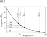
- the connections are in Figure 7 shown. A grain boundary volume of 0 to 50%, preferably 10 to 30%, is preferred. Because separating a single grain from the composite is easier than grinding a large grain smooth.
- the crystalline domains are smaller than 0.5xR t , preferably 0.2xR t , particularly preferably 0.1xRt of the remaining surface roughness.
- the absolute surface roughness R t (roughness depth), measured as a peak-to-valley value, must be taken into account for the roughness R t .
- R t is calculated from the difference between the maximum peak height R p and the maximum peak depth R v .
- both pure silicon and diamond are electrical insulators, it is also proposed to electrically dope both materials so that they have at least a low electrical conductivity. This allows electrostatic charging effects to be avoided.
- the doping processes for silicon are sufficiently described in the literature.
- diamond it is suggested to use doping with boron or with nitrogen or ammonia. ( N. Wiora et al., Synthesis and Characterization of n-type Nitrogenated, Nanocrystalline Diamond Micron Materials and Nanomaterials, 15:96-98 ). It is also proposed that in the case of insulating materials, the friction partners consist of the same material and therefore have the same work function. This means that electrostatic charging due to mere frictional contact can be largely ruled out.
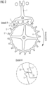
- Figure 1 now shows a Swiss anchor escapement in the top view.
- the Figure 1A shows the state of the anchor 1 and the wheel 4 at the start and the Figure 1B after the unrest has passed zero.
- the escape wheel 4 has 20 piston teeth 5 in the case shown here.
- the armature 1 has an input pallet 2 and an output pallet 2 ', which alternately engage with the piston teeth 5 of the wheel 4.
- the Figures 1A and 1B show the rest states in each case.
- the new position of the piston tooth 5 is also shown.
- the stopper 20 serves as a stop for the anchor 4. Alternatively, such a stop can be dispensed with by introducing a shoulder in the anchor pallets.
- Such an embodiment is, for example, in the Swiss patent specification CH 5 67293 , here in particular the Figures 5 and 6 , described.
- Figure 2 now shows the one in the Figure 1 Swiss anchor escapement described in more detail, here during the dynamic implusion process (interaction between piston tooth 5 and anchor pallet 2 or 2 ').
- the essential areas are shown enlarged.
- the piston tooth 5 of the wheel 4 has already left the rest surface 22 and is located on the lifting surface 23 of the input pallet 2. Due to the applied torque of the gear train, the piston tooth 5 now slides over the lifting surface 23 of the input pallet 2 and thereby pushes the anchor pallet 2 back.
- Figure 3 referred.
- the position at which the pallet 2 is in engagement with the anchor 5 is shown at 21.
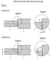
- Figure 3 now shows in an enlarged view how the contact surfaces relate to each other.
- the pallets 2, 2' of the anchor 1 are made thicker than the piston teeth 5 of the wheel. This can be seen in particular from section AA.
- B is shown in more detail, with 25 again showing the point at which the pallet 2 is in engagement with the tooth 5. Due to the manufacturing process, the flanks 12 of the tooth 5 and the flanks 8 of the pallets 2 of the components never have an angle of 90° to the surface (so-called non-verticality).
- the components can be installed in such a way that the functional surfaces are plane-parallel to one another.
- the components are now usually mounted in such a way that the flanks are aligned with one another, so that a clearance angle ⁇ results.
- a symmetrical non-verticality of 2° was assumed. Around 1° per component edge is typical. It is now not necessary that the functional surfaces of wheel 4 and armature 1 have to have the same deviation from the ideal.
- Figure 4 now shows the behavior of the components to one another when the position of the clock changes.
- the starting position is shown in the left part at section AA and detail C, as previously shown in Figure 3 has been described in more detail.
- the bearing play also changes, ie the relative position of the components to one another.
- It is important that the piston tooth 5 of the wheel 4 is now engaged at point 25 due to the clearance angle ⁇ , but still works on the same contact surface A 0 .
- the contact point 25 of the lever surface 23 of the input side 2 is now shifted by the amount ⁇ h.
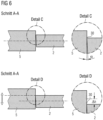
- Figure 5 now shows an embodiment according to the invention.
- the flanks 12 of the piston tooth 5 as well as the flank 8 of the pallet 2 have a non-verticality due to the manufacturing process.
- the components are mounted in such a way that the flanks 8, 12 are aligned with one another, so that analogous to Figures 3 and 4 a clearance angle ⁇ results.
- Figure 5 shown in detail B In the embodiment according to the Figure 5 a symmetrical non-verticality of 2° was again assumed.
- about 1° per component flank 8 or 12 is preferred. It is also not necessary that the functional surfaces of wheel 4 and armature 1 have to have the same deviation from the ideal.
- Figure 6 shows the sectional view Figure 5 now if there is a change in the storage of the watch. This occurs again when the clock is turned, for example.
- the bearing play changes the relative position of the components to one another. This also results in a shift ⁇ h of the contact points 30 between the piston tooth 5 and the input pallet 2.
- the lever surface of the pallet 2 due to the clearance angle ⁇ , now still works on the same geometric contact surface A 0 (defined contact surfaces).
- the contact point 30 of the piston tooth 5 of the escape wheel 4 is shifted by the amount ⁇ h.
- Figure 7 now shows how the grain boundary volume relates to the grain size. How out Figure 7 As can be seen, smaller grains inevitably result in an increased grain boundary volume.
- a grain boundary volume of 0 to 50% is preferred, preferably 10 to 30%.
- Figure 8 shows in an enlarged view ( Figure 8a ) a piston tooth 5 and in Figure 8b the in Figure 8a marked enlarged section
- the representation in Figure 8b shows a piston tooth 5 according to the invention after 9 days of continuous running of the escapement.
- the geometric contact area A 0 which is represented by the dark part, can have a width of 0.5 to 20 ⁇ m, preferably from 1 to 10 ⁇ m, most preferably from 1 to 5 ⁇ m.
- the real contact area A R (light stripe) is limited to the uppermost part of the component due to the non-verticality of the component. Under 25,000x magnification it can be seen that the geometric contact surface A 0 in the example case is only about 1.5 to 2 ⁇ m wide.
- the dark color surrounding the geometric contact surface A 0 results from abrasion of the originally microscopically rough component surface.
- the bright area has been polished by the function of the component and is actually in contact with the pallets (2,2'). According to the invention, this is referred to as the real contact area A R.
- the difference in brightness makes it possible to determine the geometric and real contact area and to form the quotient.
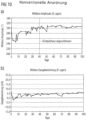
- the amplitude values ( FIG. 10a ) are measured using a Witschi M1 timer (acoustically) and checked optically.
- the values shown are arithmetic mean values from 6 layers each (dial top, bottom; crown top, right, bottom, left).
- the measurement interval was 30 seconds in each case, the stabilization time was also 30s.
- the average rate deviation ( Fig. 10b ) these are also arithmetic mean values from 6 layers each (see amplitude measurement).
- the typical drop in amplitude within the first 7 days is clearly visible.
- the amplitude then slowly increases again and reaches its starting value after approx. 40 days. This behavior is also explained by the shrinkage of the components.
- the defined contact surface of the wheel is polished by the frictional contact with the anchor pallets. If the airfoil proportion of more than 50% is reached, no further removal takes place and a tribofilm can form on the contact surfaces. The dashed line shows when the run-in phase is complete.
- Figure 11 are those determined experimentally Amplitudes and rate values of an ETA caliber type 2892A2 equipped with the diamond-coated escapement according to the invention without a soft sp2-containing top layer according to. EP 2 236 455 .
- the escapement runs without lubrication.
- the amplitude values ( Fig. 11a ) are in turn measured using a Witschi M1 timer (acoustically) and checked optically.
- the values shown are again arithmetic mean values from 6 layers each (dial top, bottom; crown top, right, bottom, left).
- the measuring interval was 30 seconds in each case, the stabilization time was also 30s.
- the average rate deviation ( Fig. 11b ) these are also arithmetic mean values from 6 layers each (see amplitude measurement).
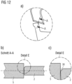
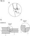
- FIG 13 Another embodiment is shown, here an embodiment in which the pallet 2 has a rounded edge.
- Figure 13b the top view of such a configuration is again shown schematically in detail and in the Figures 13a and 13b in each case an enlarged view of the contact point 30.
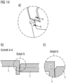
- Figure 14 A further embodiment is now shown, in which the pallet 2 has a design as already shown in the Figure 12 has been described, but here the piston tooth 5 is now angled.
- Figure 14 A section of the top view of the configuration is shown in A and in the Figures 14b and 14c enlarged representations in each case, whereby the contact point 30 can also be seen here, so that a geometric contact surface A 0 can then form here again.
Landscapes
- Physics & Mathematics (AREA)
- General Physics & Mathematics (AREA)
- Gears, Cams (AREA)
- Micromachines (AREA)
Claims (9)
- Échappement pour un chronomètre mécanique comprenant une ancre pivotante (1) avec des palettes d'ancrage (2, 2') et une roue d'ancre (4) pouvant être sollicitée par un couple, qui comprend des dents (5, 5', 5") orientées vers l'extérieur sur sa circonférence extérieure, dans lequel, lors du fonctionnement de l'échappement, un mouvement relatif glissant a lieu, dans lequel les flancs avant (8) des palettes (2, 2') entrent en contact successivement et de manière alternée avec les flancs avant des dents (5, 5', 5"), dans lequellors du fonctionnement de l'échappement, dans les flancs avant (12) des dents (5, 5', 5"), dans la direction du mouvement relatif, apparaissent des surfaces de contact géométriques A0 sous la forme d'une bande, qui présentent une largeur de 0,5 à 5 µm, et les flancs avant (8) des palettes (2, 2') sont conçus de façon à ce que, lors du fonctionnement de l'échappement dans la direction du mouvement relatif, à chaque contact d'un des flancs avant (8) des palettes (2, 2') avec un des flancs avant (12) des dents (5, 5', 5") de la roue (4), toujours la même surface de contact A0 du flanc avant (8) des palettes (2, 2') est emboîtée avec le flanc avant (12) des dents (5, 5', 5") de la roue (4), dans lequel au moins les flancs (8) des palettes (2, 2') et le flanc avant (12) des dents (5, 5', 5") comprennent un revêtement en matériau dur, une surface de contact réelle AR polie ou adoucie étant formée dans la surface de contact géométrique A0, le rapport AR/A0 se trouvant entre 20 et 90 %,caractérisé en ce que le revêtement en matériau dur présente une épaisseur de couche de 1 à 100 µm et est sélectionné parmi un oxyde de silicium, plus particulièrement du SiO2, ou des oxydes non stoechiométriques de formule SixOy, dans lesquels x et y sont des nombres entiers, ou parmi des carbures de silicium ou du nitrure de silicium ou du diamant, plus particulièrement un diamant nanocristallin, ou un carbone de type diamant (DLC) ou un rubis ou un saphir.
- Échappement selon la revendication 1, caractérisé en ce que les flancs avant (8) des palettes (2, 2') et les flancs avant (12) des dents (5, 5', 5") présentent une non-verticalité et sont disposés les uns par rapport aux autres de façon à ce qu'il en résulte un angle libre α d'au moins 0,1° à 5°, de préférence de 0,1° à 3° et plus particulièrement de préférence de 0,1° à 1°.
- Échappement selon l'une des revendications 1 à 2, caractérisé en ce que les flancs avant (8) des palettes (2, 2') se présentent sous la forme d'un toit avec une crête centrale ou présentent une forme cylindrique avec une surface bombée vers l'extérieur, la surface de contact géométrique A0 étant formée par la crête centrale, respectivement par la surface bombée vers l'extérieur.
- Échappement selon l'une des revendications 1 à 3, caractérisé en ce que les flancs avant (8) des palettes (2, 2') présentent la forme de surfaces lisses et planes qui s'écartent au plus de ± 2°, de préférence 1°, plus particulièrement de préférence de moins de 0,5° de la perpendiculaire, par rapport au côté supérieur des palettes, dans lequel la surface de contact géométrique A0 est constituée de l'arête orientée vers l'extérieur.
- Échappement selon l'une des revendications 1 à 4,
caractérisé en ce que l'épaisseur des palettes (2, 2') est de 50 à 180 µm et l'épaisseur des dents (5, 5', 5") de la roue dentée (4) est de 100 à 250 µm, dans lequel l'épaisseur des palettes (2, 2') est inférieure à l'épaisseur des dents (5, 5', 5") de la roue dentée (4), relativement à la perpendiculaire par rapport au côté supérieur. - Échappement selon l'une des revendications 1 à 5, caractérisé en ce que le revêtement en matériau dur présente une épaisseur de couche de 5 à 50 µm.
- Échappement selon l'une des revendications précédentes, caractérisé en ce que la couche de diamant nanocristallin présente au moins une des propriétés suivantes :a) la couche de diamant nanocristallin présente une résistance à la rupture par flexion de 1 à 10 GPa, de préférence d'au moins 2 GPa, de préférence d'au moins 5 GPa et plus particulièrement de préférence de 7 GPa,b) la couche de diamant nanocristallin présente une épaisseur de couche dans la zone de contact de 0,5 µm à 100 µm, de préférence de 2 à 50 µm et plus particulièrement de préférence de 2 à 10 µm etc) la couche de diamant nanocristallin présente un module d'élasticité de 700 GPa à 1143 GPa, de préférence de 400 GPa à 900 GPa.
- Échappement selon au moins l'une des revendications précédentes, caractérisé en ce qu'au moins la roue d'ancre a été réalisée à partir d'un matériau qui présente une densité de 0,5 g/cm3 à 4,5 g/cm3, plus particulièrement de préférence de 1 à 4 g/cm3.
- Échappement selon au moins l'une des revendications 1 à 8, caractérisé en ce que les palettes (2, 2') et/ou l'ancre (1) et/ou la roue (4) sont réalisées en silicium et sont pourvues de la couche de matériau dur.
Priority Applications (2)
| Application Number | Priority Date | Filing Date | Title |
|---|---|---|---|
| EP14185997.5A EP3001256B2 (fr) | 2014-09-23 | 2014-09-23 | Échappement à ancre |
| CH01837/14A CH710169B1 (de) | 2014-09-23 | 2014-11-28 | Ankerhemmung. |
Applications Claiming Priority (1)
| Application Number | Priority Date | Filing Date | Title |
|---|---|---|---|
| EP14185997.5A EP3001256B2 (fr) | 2014-09-23 | 2014-09-23 | Échappement à ancre |
Publications (3)
| Publication Number | Publication Date |
|---|---|
| EP3001256A1 EP3001256A1 (fr) | 2016-03-30 |
| EP3001256B1 EP3001256B1 (fr) | 2020-09-09 |
| EP3001256B2 true EP3001256B2 (fr) | 2024-02-07 |
Family
ID=51589168
Family Applications (1)
| Application Number | Title | Priority Date | Filing Date |
|---|---|---|---|
| EP14185997.5A Active EP3001256B2 (fr) | 2014-09-23 | 2014-09-23 | Échappement à ancre |
Country Status (2)
| Country | Link |
|---|---|
| EP (1) | EP3001256B2 (fr) |
| CH (1) | CH710169B1 (fr) |
Families Citing this family (1)
| Publication number | Priority date | Publication date | Assignee | Title |
|---|---|---|---|---|
| DE102023107683A1 (de) | 2023-03-27 | 2023-07-27 | Damasko Präzisionstechnik GmbH & Co. KG | Ankerhemmung |
Citations (12)
| Publication number | Priority date | Publication date | Assignee | Title |
|---|---|---|---|---|
| SU47937A1 (ru) † | 1935-10-31 | 1936-07-31 | В.П. Козлов | Анкерный ход дл часов с балансом |
| CH357021A (fr) † | 1959-09-03 | 1961-09-15 | John Perret Fils De | Echappement à ancre de pièce d'horlogerie |
| FR1485813A (fr) † | 1966-06-17 | 1967-06-23 | Pforzheimer Uhren Rohwerke | Mouvement de montre pour montres-bracelets |
| CH567293B5 (fr) † | 1972-07-19 | 1975-09-30 | Far Fab Assortiments Reunies | Echappament à ancre pour pièce d'horlogerie |
| CH612308GA3 (en) † | 1975-09-10 | 1979-07-31 | Lever escapement | |
| EP0732635B1 (fr) † | 1995-03-17 | 2000-06-07 | C.S.E.M. Centre Suisse D'electronique Et De Microtechnique Sa | Procédé de réalisation d'une piéce de micro-mécanique |
| EP1233314A1 (fr) † | 2001-02-15 | 2002-08-21 | DAMASKO, Konrad | Mouvement d'horlogerie |
| WO2004092049A1 (fr) † | 2003-04-17 | 2004-10-28 | Gfd Gesellschaft Für Diamantprodukte Mbh | Composant micromecanique et son procede de production |
| EP1904901B1 (fr) † | 2005-06-28 | 2008-12-03 | ETA SA Manufacture Horlogère Suisse | Piece de micro-mecanique renforcee |
| WO2009049591A1 (fr) † | 2007-10-18 | 2009-04-23 | Konrad Damasko | Procédé de fabrication d'éléments fonctionnels pour des mouvements d'horlogerie et élément fonctionnel fabriqué selon ce procédé |
| EP2236455A1 (fr) † | 2009-04-02 | 2010-10-06 | GFD Gesellschaft für Diamantprodukte mbH | Composant micromécanique avec une usure réduite |
| EP2107434B1 (fr) † | 2008-04-02 | 2013-09-18 | Manufacture et fabrique de montres et chronomètres Ulysse Nardin Le Locle SA | Chronomètre mécanique |
-
2014
- 2014-09-23 EP EP14185997.5A patent/EP3001256B2/fr active Active
- 2014-11-28 CH CH01837/14A patent/CH710169B1/de not_active IP Right Cessation
Patent Citations (14)
| Publication number | Priority date | Publication date | Assignee | Title |
|---|---|---|---|---|
| SU47937A1 (ru) † | 1935-10-31 | 1936-07-31 | В.П. Козлов | Анкерный ход дл часов с балансом |
| CH357021A (fr) † | 1959-09-03 | 1961-09-15 | John Perret Fils De | Echappement à ancre de pièce d'horlogerie |
| FR1485813A (fr) † | 1966-06-17 | 1967-06-23 | Pforzheimer Uhren Rohwerke | Mouvement de montre pour montres-bracelets |
| CH567293B5 (fr) † | 1972-07-19 | 1975-09-30 | Far Fab Assortiments Reunies | Echappament à ancre pour pièce d'horlogerie |
| CH612308GA3 (en) † | 1975-09-10 | 1979-07-31 | Lever escapement | |
| EP0732635B1 (fr) † | 1995-03-17 | 2000-06-07 | C.S.E.M. Centre Suisse D'electronique Et De Microtechnique Sa | Procédé de réalisation d'une piéce de micro-mécanique |
| EP1233314A1 (fr) † | 2001-02-15 | 2002-08-21 | DAMASKO, Konrad | Mouvement d'horlogerie |
| WO2004092049A1 (fr) † | 2003-04-17 | 2004-10-28 | Gfd Gesellschaft Für Diamantprodukte Mbh | Composant micromecanique et son procede de production |
| DE10317889A1 (de) † | 2003-04-17 | 2004-11-18 | GFD-Gesellschaft für Diamantprodukte mbH | Mikromechanisches Bauteil und Verfahren zu seiner Herstellung |
| EP1622826B1 (fr) † | 2003-04-17 | 2007-06-13 | GFD Gesellschaft für Diamantprodukte mbH | Composants micromecaniques d'horlogerie et ses procedes de production |
| EP1904901B1 (fr) † | 2005-06-28 | 2008-12-03 | ETA SA Manufacture Horlogère Suisse | Piece de micro-mecanique renforcee |
| WO2009049591A1 (fr) † | 2007-10-18 | 2009-04-23 | Konrad Damasko | Procédé de fabrication d'éléments fonctionnels pour des mouvements d'horlogerie et élément fonctionnel fabriqué selon ce procédé |
| EP2107434B1 (fr) † | 2008-04-02 | 2013-09-18 | Manufacture et fabrique de montres et chronomètres Ulysse Nardin Le Locle SA | Chronomètre mécanique |
| EP2236455A1 (fr) † | 2009-04-02 | 2010-10-06 | GFD Gesellschaft für Diamantprodukte mbH | Composant micromécanique avec une usure réduite |
Non-Patent Citations (5)
| Title |
|---|
| Auszug aus Chronos, Magazin für Uhren, Verlag: Ebner Media Group, Ausgabe 04.2011, Seiten 60 - 68 † |
| Auszüge aus dem Originalkatalog „MunichTime10", Uhren Ausstellung Hotel Bayrischer Hof 05.-07.11.2010 † |
| Eingabe Dritter vom 15.09.2010 mit Anlagen. Eingabe Dritter vom 16.08.2012 mit Anlagen zur EP 1 904 901 B1 (D6) † |
| Homepage-Auszug „Die Hemmung", abgerufen unter www.damasko.de, per "wayback machine" (archive.org), am 29.Dezember 2005 und in der am 12. April 2010 † |
| Internet-Veröffentlichung: Protron Mikrotechnik † |
Also Published As
| Publication number | Publication date |
|---|---|
| EP3001256B1 (fr) | 2020-09-09 |
| CH710169B1 (de) | 2019-06-14 |
| CH710169A2 (de) | 2016-03-31 |
| EP3001256A1 (fr) | 2016-03-30 |
Similar Documents
| Publication | Publication Date | Title |
|---|---|---|
| EP2107434B1 (fr) | Chronomètre mécanique | |
| EP2511229B1 (fr) | Composant micromécanique doté de flancs renforcés | |
| EP2687916B1 (fr) | Ancre pour un échappement de montre dans une montre mécanique | |
| EP2236455B1 (fr) | Composant micromécanique avec une usure réduite | |
| DE69909236T2 (de) | Koaxiale Ankerhemmung | |
| EP2727880B2 (fr) | Composant micromécanique tridimensionnel chanfreiné et son procédé de fabrication | |
| DE102008061182A1 (de) | Verfahren zum Herstellen eines Mikrobauteils | |
| EP3101484A1 (fr) | Systeme oscillant mecanique pour montres et procede de fabrication d'un systeme oscillant mecanique pour montres | |
| CH703781A2 (de) | Uhrrad und Uhr. | |
| EP3001256B2 (fr) | Échappement à ancre | |
| DE102013104248B3 (de) | Verfahren zur Herstellung einer Spiralfeder für mechanische Uhrwerke | |
| EP1233314A1 (fr) | Mouvement d'horlogerie | |
| DE4127639A1 (de) | Reibpaarung und verfahren zu ihrer herstellung | |
| EP3074550B1 (fr) | Revêtement doté d'une couche à base de mo-n comprenant la phase delta du nitrure de molybdène | |
| CH702171A2 (de) | Uhrenbestandteil und Uhr. | |
| DE102014102081A1 (de) | Mikromechanisches Bauteil und Verfahren zur Herstellung eines mikromechanischen Bauteils | |
| DE10062933B4 (de) | Ankerhemmung für eine Uhr | |
| DE2205043A1 (de) | Datumsanzeigevorrichtung für Uhren | |
| DE19636827C1 (de) | Piezoelektrischer Antrieb | |
| DE2733810A1 (de) | Uhrenteil und verfahren zu seiner herstellung | |
| DE2210404A1 (de) | Schwingungsmotor | |
| DE531471C (de) | Stoppuhr | |
| DE102023107683A1 (de) | Ankerhemmung | |
| EP4180879A1 (fr) | Module micromécanique, son procédé de fabrication et son utilisation | |
| DE2241606C3 (de) | Gaswechselventil-Betätigungshebel, insbesondere Kipp- bzw. Schwinghebel für Brennkraftmaschinen |
Legal Events
| Date | Code | Title | Description |
|---|---|---|---|
| PUAI | Public reference made under article 153(3) epc to a published international application that has entered the european phase |
Free format text: ORIGINAL CODE: 0009012 |
|
| AK | Designated contracting states |
Kind code of ref document: A1 Designated state(s): AL AT BE BG CH CY CZ DE DK EE ES FI FR GB GR HR HU IE IS IT LI LT LU LV MC MK MT NL NO PL PT RO RS SE SI SK SM TR |
|
| AX | Request for extension of the european patent |
Extension state: BA ME |
|
| 17P | Request for examination filed |
Effective date: 20160721 |
|
| RBV | Designated contracting states (corrected) |
Designated state(s): AL AT BE BG CH CY CZ DE DK EE ES FI FR GB GR HR HU IE IS IT LI LT LU LV MC MK MT NL NO PL PT RO RS SE SI SK SM TR |
|
| STAA | Information on the status of an ep patent application or granted ep patent |
Free format text: STATUS: EXAMINATION IS IN PROGRESS |
|
| 17Q | First examination report despatched |
Effective date: 20180108 |
|
| GRAP | Despatch of communication of intention to grant a patent |
Free format text: ORIGINAL CODE: EPIDOSNIGR1 |
|
| STAA | Information on the status of an ep patent application or granted ep patent |
Free format text: STATUS: GRANT OF PATENT IS INTENDED |
|
| INTG | Intention to grant announced |
Effective date: 20200409 |
|
| RIN1 | Information on inventor provided before grant (corrected) |
Inventor name: GLUCHE, PETER Inventor name: GRETZSCHEL, RALPH |
|
| GRAS | Grant fee paid |
Free format text: ORIGINAL CODE: EPIDOSNIGR3 |
|
| GRAA | (expected) grant |
Free format text: ORIGINAL CODE: 0009210 |
|
| STAA | Information on the status of an ep patent application or granted ep patent |
Free format text: STATUS: THE PATENT HAS BEEN GRANTED |
|
| AK | Designated contracting states |
Kind code of ref document: B1 Designated state(s): AL AT BE BG CH CY CZ DE DK EE ES FI FR GB GR HR HU IE IS IT LI LT LU LV MC MK MT NL NO PL PT RO RS SE SI SK SM TR |
|
| REG | Reference to a national code |
Ref country code: GB Ref legal event code: FG4D Free format text: NOT ENGLISH |
|
| REG | Reference to a national code |
Ref country code: AT Ref legal event code: REF Ref document number: 1312367 Country of ref document: AT Kind code of ref document: T Effective date: 20200915 Ref country code: CH Ref legal event code: EP |
|
| REG | Reference to a national code |
Ref country code: DE Ref legal event code: R096 Ref document number: 502014014722 Country of ref document: DE |
|
| REG | Reference to a national code |
Ref country code: IE Ref legal event code: FG4D Free format text: LANGUAGE OF EP DOCUMENT: GERMAN |
|
| REG | Reference to a national code |
Ref country code: CH Ref legal event code: NV Representative=s name: DENNEMEYER AG, CH |
|
| REG | Reference to a national code |
Ref country code: LT Ref legal event code: MG4D |
|
| PG25 | Lapsed in a contracting state [announced via postgrant information from national office to epo] |
Ref country code: BG Free format text: LAPSE BECAUSE OF FAILURE TO SUBMIT A TRANSLATION OF THE DESCRIPTION OR TO PAY THE FEE WITHIN THE PRESCRIBED TIME-LIMIT Effective date: 20201209 Ref country code: NO Free format text: LAPSE BECAUSE OF FAILURE TO SUBMIT A TRANSLATION OF THE DESCRIPTION OR TO PAY THE FEE WITHIN THE PRESCRIBED TIME-LIMIT Effective date: 20201209 Ref country code: LT Free format text: LAPSE BECAUSE OF FAILURE TO SUBMIT A TRANSLATION OF THE DESCRIPTION OR TO PAY THE FEE WITHIN THE PRESCRIBED TIME-LIMIT Effective date: 20200909 Ref country code: GR Free format text: LAPSE BECAUSE OF FAILURE TO SUBMIT A TRANSLATION OF THE DESCRIPTION OR TO PAY THE FEE WITHIN THE PRESCRIBED TIME-LIMIT Effective date: 20201210 Ref country code: FI Free format text: LAPSE BECAUSE OF FAILURE TO SUBMIT A TRANSLATION OF THE DESCRIPTION OR TO PAY THE FEE WITHIN THE PRESCRIBED TIME-LIMIT Effective date: 20200909 Ref country code: SE Free format text: LAPSE BECAUSE OF FAILURE TO SUBMIT A TRANSLATION OF THE DESCRIPTION OR TO PAY THE FEE WITHIN THE PRESCRIBED TIME-LIMIT Effective date: 20200909 Ref country code: HR Free format text: LAPSE BECAUSE OF FAILURE TO SUBMIT A TRANSLATION OF THE DESCRIPTION OR TO PAY THE FEE WITHIN THE PRESCRIBED TIME-LIMIT Effective date: 20200909 |
|
| REG | Reference to a national code |
Ref country code: NL Ref legal event code: MP Effective date: 20200909 |
|
| PG25 | Lapsed in a contracting state [announced via postgrant information from national office to epo] |
Ref country code: LV Free format text: LAPSE BECAUSE OF FAILURE TO SUBMIT A TRANSLATION OF THE DESCRIPTION OR TO PAY THE FEE WITHIN THE PRESCRIBED TIME-LIMIT Effective date: 20200909 Ref country code: PL Free format text: LAPSE BECAUSE OF FAILURE TO SUBMIT A TRANSLATION OF THE DESCRIPTION OR TO PAY THE FEE WITHIN THE PRESCRIBED TIME-LIMIT Effective date: 20200909 Ref country code: RS Free format text: LAPSE BECAUSE OF FAILURE TO SUBMIT A TRANSLATION OF THE DESCRIPTION OR TO PAY THE FEE WITHIN THE PRESCRIBED TIME-LIMIT Effective date: 20200909 |
|
| PG25 | Lapsed in a contracting state [announced via postgrant information from national office to epo] |
Ref country code: NL Free format text: LAPSE BECAUSE OF FAILURE TO SUBMIT A TRANSLATION OF THE DESCRIPTION OR TO PAY THE FEE WITHIN THE PRESCRIBED TIME-LIMIT Effective date: 20200909 Ref country code: PT Free format text: LAPSE BECAUSE OF FAILURE TO SUBMIT A TRANSLATION OF THE DESCRIPTION OR TO PAY THE FEE WITHIN THE PRESCRIBED TIME-LIMIT Effective date: 20210111 Ref country code: RO Free format text: LAPSE BECAUSE OF FAILURE TO SUBMIT A TRANSLATION OF THE DESCRIPTION OR TO PAY THE FEE WITHIN THE PRESCRIBED TIME-LIMIT Effective date: 20200909 Ref country code: SM Free format text: LAPSE BECAUSE OF FAILURE TO SUBMIT A TRANSLATION OF THE DESCRIPTION OR TO PAY THE FEE WITHIN THE PRESCRIBED TIME-LIMIT Effective date: 20200909 Ref country code: CZ Free format text: LAPSE BECAUSE OF FAILURE TO SUBMIT A TRANSLATION OF THE DESCRIPTION OR TO PAY THE FEE WITHIN THE PRESCRIBED TIME-LIMIT Effective date: 20200909 Ref country code: EE Free format text: LAPSE BECAUSE OF FAILURE TO SUBMIT A TRANSLATION OF THE DESCRIPTION OR TO PAY THE FEE WITHIN THE PRESCRIBED TIME-LIMIT Effective date: 20200909 |
|
| PG25 | Lapsed in a contracting state [announced via postgrant information from national office to epo] |
Ref country code: AL Free format text: LAPSE BECAUSE OF FAILURE TO SUBMIT A TRANSLATION OF THE DESCRIPTION OR TO PAY THE FEE WITHIN THE PRESCRIBED TIME-LIMIT Effective date: 20200909 Ref country code: ES Free format text: LAPSE BECAUSE OF FAILURE TO SUBMIT A TRANSLATION OF THE DESCRIPTION OR TO PAY THE FEE WITHIN THE PRESCRIBED TIME-LIMIT Effective date: 20200909 Ref country code: IS Free format text: LAPSE BECAUSE OF FAILURE TO SUBMIT A TRANSLATION OF THE DESCRIPTION OR TO PAY THE FEE WITHIN THE PRESCRIBED TIME-LIMIT Effective date: 20210109 |
|
| REG | Reference to a national code |
Ref country code: DE Ref legal event code: R026 Ref document number: 502014014722 Country of ref document: DE |
|
| PLBI | Opposition filed |
Free format text: ORIGINAL CODE: 0009260 |
|
| PLBI | Opposition filed |
Free format text: ORIGINAL CODE: 0009260 |
|
| REG | Reference to a national code |
Ref country code: BE Ref legal event code: MM Effective date: 20200930 |
|
| PG25 | Lapsed in a contracting state [announced via postgrant information from national office to epo] |
Ref country code: LU Free format text: LAPSE BECAUSE OF NON-PAYMENT OF DUE FEES Effective date: 20200923 Ref country code: SK Free format text: LAPSE BECAUSE OF FAILURE TO SUBMIT A TRANSLATION OF THE DESCRIPTION OR TO PAY THE FEE WITHIN THE PRESCRIBED TIME-LIMIT Effective date: 20200909 Ref country code: MC Free format text: LAPSE BECAUSE OF FAILURE TO SUBMIT A TRANSLATION OF THE DESCRIPTION OR TO PAY THE FEE WITHIN THE PRESCRIBED TIME-LIMIT Effective date: 20200909 |
|
| 26 | Opposition filed |
Opponent name: HORAGE S.A. Effective date: 20210608 |
|
| 26 | Opposition filed |
Opponent name: DAMASKO PRAEZISIONSTECHNIK GMBH & CO. KG Effective date: 20210609 |
|
| GBPC | Gb: european patent ceased through non-payment of renewal fee |
Effective date: 20201209 |
|
| PG25 | Lapsed in a contracting state [announced via postgrant information from national office to epo] |
Ref country code: DK Free format text: LAPSE BECAUSE OF FAILURE TO SUBMIT A TRANSLATION OF THE DESCRIPTION OR TO PAY THE FEE WITHIN THE PRESCRIBED TIME-LIMIT Effective date: 20200909 Ref country code: BE Free format text: LAPSE BECAUSE OF NON-PAYMENT OF DUE FEES Effective date: 20200930 Ref country code: SI Free format text: LAPSE BECAUSE OF FAILURE TO SUBMIT A TRANSLATION OF THE DESCRIPTION OR TO PAY THE FEE WITHIN THE PRESCRIBED TIME-LIMIT Effective date: 20200909 Ref country code: IE Free format text: LAPSE BECAUSE OF NON-PAYMENT OF DUE FEES Effective date: 20200923 |
|
| PLAX | Notice of opposition and request to file observation + time limit sent |
Free format text: ORIGINAL CODE: EPIDOSNOBS2 |
|
| PG25 | Lapsed in a contracting state [announced via postgrant information from national office to epo] |
Ref country code: IT Free format text: LAPSE BECAUSE OF FAILURE TO SUBMIT A TRANSLATION OF THE DESCRIPTION OR TO PAY THE FEE WITHIN THE PRESCRIBED TIME-LIMIT Effective date: 20200909 |
|
| REG | Reference to a national code |
Ref country code: AT Ref legal event code: MM01 Ref document number: 1312367 Country of ref document: AT Kind code of ref document: T Effective date: 20200923 |
|
| PG25 | Lapsed in a contracting state [announced via postgrant information from national office to epo] |
Ref country code: GB Free format text: LAPSE BECAUSE OF NON-PAYMENT OF DUE FEES Effective date: 20201209 |
|
| PG25 | Lapsed in a contracting state [announced via postgrant information from national office to epo] |
Ref country code: AT Free format text: LAPSE BECAUSE OF NON-PAYMENT OF DUE FEES Effective date: 20200923 |
|
| PLBB | Reply of patent proprietor to notice(s) of opposition received |
Free format text: ORIGINAL CODE: EPIDOSNOBS3 |
|
| PG25 | Lapsed in a contracting state [announced via postgrant information from national office to epo] |
Ref country code: IS Free format text: LAPSE BECAUSE OF FAILURE TO SUBMIT A TRANSLATION OF THE DESCRIPTION OR TO PAY THE FEE WITHIN THE PRESCRIBED TIME-LIMIT Effective date: 20210109 Ref country code: TR Free format text: LAPSE BECAUSE OF FAILURE TO SUBMIT A TRANSLATION OF THE DESCRIPTION OR TO PAY THE FEE WITHIN THE PRESCRIBED TIME-LIMIT Effective date: 20200909 Ref country code: MT Free format text: LAPSE BECAUSE OF FAILURE TO SUBMIT A TRANSLATION OF THE DESCRIPTION OR TO PAY THE FEE WITHIN THE PRESCRIBED TIME-LIMIT Effective date: 20200909 Ref country code: CY Free format text: LAPSE BECAUSE OF FAILURE TO SUBMIT A TRANSLATION OF THE DESCRIPTION OR TO PAY THE FEE WITHIN THE PRESCRIBED TIME-LIMIT Effective date: 20200909 |
|
| PG25 | Lapsed in a contracting state [announced via postgrant information from national office to epo] |
Ref country code: MK Free format text: LAPSE BECAUSE OF FAILURE TO SUBMIT A TRANSLATION OF THE DESCRIPTION OR TO PAY THE FEE WITHIN THE PRESCRIBED TIME-LIMIT Effective date: 20200909 |
|
| PLAY | Examination report in opposition despatched + time limit |
Free format text: ORIGINAL CODE: EPIDOSNORE2 |
|
| PLBC | Reply to examination report in opposition received |
Free format text: ORIGINAL CODE: EPIDOSNORE3 |
|
| REG | Reference to a national code |
Ref country code: CH Ref legal event code: PK Free format text: TITEL |
|
| P01 | Opt-out of the competence of the unified patent court (upc) registered |
Effective date: 20230525 |
|
| PGFP | Annual fee paid to national office [announced via postgrant information from national office to epo] |
Ref country code: FR Payment date: 20230928 Year of fee payment: 10 Ref country code: DE Payment date: 20230921 Year of fee payment: 10 |
|
| PUAH | Patent maintained in amended form |
Free format text: ORIGINAL CODE: 0009272 |
|
| STAA | Information on the status of an ep patent application or granted ep patent |
Free format text: STATUS: PATENT MAINTAINED AS AMENDED |
|
| PGFP | Annual fee paid to national office [announced via postgrant information from national office to epo] |
Ref country code: CH Payment date: 20231001 Year of fee payment: 10 |
|
| 27A | Patent maintained in amended form |
Effective date: 20240207 |
|
| AK | Designated contracting states |
Kind code of ref document: B2 Designated state(s): AL AT BE BG CH CY CZ DE DK EE ES FI FR GB GR HR HU IE IS IT LI LT LU LV MC MK MT NL NO PL PT RO RS SE SI SK SM TR |
|
| REG | Reference to a national code |
Ref country code: DE Ref legal event code: R102 Ref document number: 502014014722 Country of ref document: DE |