EP2107019A2 - Blattzuführungsablage und Bilderzeugungsvorrichtung - Google Patents
Blattzuführungsablage und Bilderzeugungsvorrichtung Download PDFInfo
- Publication number
- EP2107019A2 EP2107019A2 EP09250911A EP09250911A EP2107019A2 EP 2107019 A2 EP2107019 A2 EP 2107019A2 EP 09250911 A EP09250911 A EP 09250911A EP 09250911 A EP09250911 A EP 09250911A EP 2107019 A2 EP2107019 A2 EP 2107019A2
- Authority
- EP
- European Patent Office
- Prior art keywords
- sheet
- bottom plates
- bottom plate
- stack
- sheet feeding
- Prior art date
- Legal status (The legal status is an assumption and is not a legal conclusion. Google has not performed a legal analysis and makes no representation as to the accuracy of the status listed.)
- Granted
Links
- 230000003247 decreasing effect Effects 0.000 claims abstract description 6
- 238000011144 upstream manufacturing Methods 0.000 claims description 3
- 238000001514 detection method Methods 0.000 description 10
- 230000004048 modification Effects 0.000 description 9
- 238000012986 modification Methods 0.000 description 9
- 230000008859 change Effects 0.000 description 8
- 239000011324 bead Substances 0.000 description 5
- 239000003814 drug Substances 0.000 description 5
- 238000007639 printing Methods 0.000 description 5
- 238000000926 separation method Methods 0.000 description 5
- 238000010276 construction Methods 0.000 description 3
- 230000007423 decrease Effects 0.000 description 3
- 239000000945 filler Substances 0.000 description 3
- 230000007246 mechanism Effects 0.000 description 3
- 238000000034 method Methods 0.000 description 3
- 230000008569 process Effects 0.000 description 3
- XEEYBQQBJWHFJM-UHFFFAOYSA-N Iron Chemical compound [Fe] XEEYBQQBJWHFJM-UHFFFAOYSA-N 0.000 description 2
- 206010024453 Ligament sprain Diseases 0.000 description 2
- 208000010040 Sprains and Strains Diseases 0.000 description 2
- 230000015572 biosynthetic process Effects 0.000 description 2
- 230000008878 coupling Effects 0.000 description 2
- 238000010168 coupling process Methods 0.000 description 2
- 238000005859 coupling reaction Methods 0.000 description 2
- 230000000694 effects Effects 0.000 description 2
- 239000011347 resin Substances 0.000 description 2
- 229920005989 resin Polymers 0.000 description 2
- 230000000630 rising effect Effects 0.000 description 2
- 229910001369 Brass Inorganic materials 0.000 description 1
- 239000004809 Teflon Substances 0.000 description 1
- 229920006362 Teflon® Polymers 0.000 description 1
- XAGFODPZIPBFFR-UHFFFAOYSA-N aluminium Chemical compound [Al] XAGFODPZIPBFFR-UHFFFAOYSA-N 0.000 description 1
- 229910052782 aluminium Inorganic materials 0.000 description 1
- 239000010951 brass Substances 0.000 description 1
- 230000000994 depressogenic effect Effects 0.000 description 1
- 238000005516 engineering process Methods 0.000 description 1
- -1 etc. Substances 0.000 description 1
- 239000003292 glue Substances 0.000 description 1
- 230000005484 gravity Effects 0.000 description 1
- 229910052742 iron Inorganic materials 0.000 description 1
- 239000000463 material Substances 0.000 description 1
- 230000009467 reduction Effects 0.000 description 1
- 238000007493 shaping process Methods 0.000 description 1
Images







Classifications
-
- B—PERFORMING OPERATIONS; TRANSPORTING
- B65—CONVEYING; PACKING; STORING; HANDLING THIN OR FILAMENTARY MATERIAL
- B65H—HANDLING THIN OR FILAMENTARY MATERIAL, e.g. SHEETS, WEBS, CABLES
- B65H1/00—Supports or magazines for piles from which articles are to be separated
- B65H1/08—Supports or magazines for piles from which articles are to be separated with means for advancing the articles to present the articles to the separating device
- B65H1/14—Supports or magazines for piles from which articles are to be separated with means for advancing the articles to present the articles to the separating device comprising positively-acting mechanical devices
-
- B—PERFORMING OPERATIONS; TRANSPORTING
- B65—CONVEYING; PACKING; STORING; HANDLING THIN OR FILAMENTARY MATERIAL
- B65H—HANDLING THIN OR FILAMENTARY MATERIAL, e.g. SHEETS, WEBS, CABLES
- B65H2220/00—Function indicators
- B65H2220/09—Function indicators indicating that several of an entity are present
-
- B—PERFORMING OPERATIONS; TRANSPORTING
- B65—CONVEYING; PACKING; STORING; HANDLING THIN OR FILAMENTARY MATERIAL
- B65H—HANDLING THIN OR FILAMENTARY MATERIAL, e.g. SHEETS, WEBS, CABLES
- B65H2403/00—Power transmission; Driving means
- B65H2403/50—Driving mechanisms
- B65H2403/51—Cam mechanisms
- B65H2403/512—Cam mechanisms involving radial plate cam
-
- B—PERFORMING OPERATIONS; TRANSPORTING
- B65—CONVEYING; PACKING; STORING; HANDLING THIN OR FILAMENTARY MATERIAL
- B65H—HANDLING THIN OR FILAMENTARY MATERIAL, e.g. SHEETS, WEBS, CABLES
- B65H2405/00—Parts for holding the handled material
- B65H2405/10—Cassettes, holders, bins, decks, trays, supports or magazines for sheets stacked substantially horizontally
- B65H2405/11—Parts and details thereof
- B65H2405/111—Bottom
- B65H2405/1117—Bottom pivotable, e.g. around an axis perpendicular to transport direction, e.g. arranged at rear side of sheet support
-
- B—PERFORMING OPERATIONS; TRANSPORTING
- B65—CONVEYING; PACKING; STORING; HANDLING THIN OR FILAMENTARY MATERIAL
- B65H—HANDLING THIN OR FILAMENTARY MATERIAL, e.g. SHEETS, WEBS, CABLES
- B65H2405/00—Parts for holding the handled material
- B65H2405/30—Other features of supports for sheets
- B65H2405/31—Supports for sheets fully removable from the handling machine, e.g. cassette
-
- B—PERFORMING OPERATIONS; TRANSPORTING
- B65—CONVEYING; PACKING; STORING; HANDLING THIN OR FILAMENTARY MATERIAL
- B65H—HANDLING THIN OR FILAMENTARY MATERIAL, e.g. SHEETS, WEBS, CABLES
- B65H2511/00—Dimensions; Position; Numbers; Identification; Occurrences
- B65H2511/10—Size; Dimensions
- B65H2511/15—Height, e.g. of stack
-
- B—PERFORMING OPERATIONS; TRANSPORTING
- B65—CONVEYING; PACKING; STORING; HANDLING THIN OR FILAMENTARY MATERIAL
- B65H—HANDLING THIN OR FILAMENTARY MATERIAL, e.g. SHEETS, WEBS, CABLES
- B65H2511/00—Dimensions; Position; Numbers; Identification; Occurrences
- B65H2511/20—Location in space
- B65H2511/21—Angle
- B65H2511/212—Rotary position
-
- B—PERFORMING OPERATIONS; TRANSPORTING
- B65—CONVEYING; PACKING; STORING; HANDLING THIN OR FILAMENTARY MATERIAL
- B65H—HANDLING THIN OR FILAMENTARY MATERIAL, e.g. SHEETS, WEBS, CABLES
- B65H2701/00—Handled material; Storage means
- B65H2701/10—Handled articles or webs
- B65H2701/19—Specific article or web
- B65H2701/1916—Envelopes and articles of mail
Definitions
- the present invention relates to an image forming apparatus and a duplicator, such as a copier, a fax, a printer, etc., and in particular, to a sheet feed tray capable of accurately holding a leading end of the topmost surface of a stack bundle of envelope like recording or printing mediums at its leading end in a sheet feeding direction at a prescribed position of a separation or conveyance mechanism while providing fine quality of constant conveyance.
- the stacking height varies.
- plural envelopes each including a glue longitudinal margin at its widthwise center e.g. a general envelop
- the center rises.
- side corners of the envelopes are accordion folded (e.g. a medicine envelope or a gusset envelope) to increase an inclusion amount
- the thickness of each of the sides becomes twice larger than that of its center, so that a center of the envelope becomes extraordinary thin in comparison with the envelope sides when stacked in the bundle state.
- a stacked bundle is depressed to decrease the thickness and accordingly thickness variation as well as the volume thereof, a performance of separating the envelopes deteriorates.
- the Japanese Registered Patent No. 3, 542, 689 attempts such that a stack use bottom plate is longitudinally divided into plural pieces to be separately pushed up by springs, respectively, so that the topmost surface of a bundle of medicine envelopes pressure contacts a conveyance roller at the leading end in the sheet feeding direction.
- a medicine envelope feeder to separate and convey the envelopes from the bundle one by one, the bundle needs to uniformly pressure contact the conveyance roller in the axial direction of the conveyance roller.
- a height of each of the bottom plates gradually becomes different from the other.
- a pressure contact force of the envelope stack against the conveyance roller made by bottom plates becomes uneven, so that qualities of separation and conveyance of the stacked envelope deteriorate.
- the separate bottom lift up system can not employ a system widely used in a sheet feeding device of an electro-photographic image forming apparatus, in which a leading end of the topmost surface of a sheet bundle is held at a prescribed height and is separated and conveyed by a pick up roller and a sheet feed roller.
- a stack height detection device is arranged in the vicinity of the pick up roller arranged almost at the widthwise center, the stack height of medicine envelopes becomes lower at the center than its both side ends.
- the both side ends contact the bottom plate of the sheet-feeding tray arranged above even the stack height detection device recognizes the height as being appropriate.
- the envelope bundle sometimes causes a problem of separation and conveyance, such as deformation of the bottom plate, breakage of a lifting device, etc., in the worst case.
- an object of the present invention is to improve such background arts technologies and provides a new and novel sheet-feeding tray.
- Such an new and novel sheet feeding tray includes a frame member, and freely upwardly swingable plural bottom plates arranged on the frame member side by side perpendicular to a sheet feeding direction.
- the bottom plates cooperatively support a stack of envelope recording mediums.
- a lifting device having plural curvature sections is provided. The plural curvature sections are respectively arranged below the bottom plates to scuff and lift the lower surface of the plural bottom plates at a section downstream of the sheet feeding direction.
- the plural curvature sections each include a different outline in accordance with a difference of a decreasing amount of a thickness of the stack during sheet feeding.
- the different outlines enable the topmost surface of the stack to be almost horizontal.
- each of plural bottom plates includes one of a concave and convex portion and a friction-decreasing member on the recording medium stacking surface extending in the sheet feeding direction.
- the lifting device includes one of a concave and convex portion and a friction decreasing member on the surface of the curvature section scuffing the bottom plates.
- the width of the most downstream end in the sheet feed direction of each of the plural bottom plates is different from that at a portion scuffing the bottom plate.
- the swinging center of one of the at least two bottom plates is different from the other.
- each of the plural bottom plates includes one of a concave and convex section or a hole engageable with the lifting member at the upstream end in the sheet feed direction.
- the lifting member is formed from a single member.
- the lifting member includes at least two cams and a rotational shaft fitting into the at least two cams, each of said at least two cams including a fitted position.
- FIG. 1 an outline of an image forming apparatus of a laser printer including a sheet feed tray according to one embodiment of the present invention is described.
- an image formation section including a photoconductive member, an exposure device, and a developing device or the like
- an image formed by an electro-photographic system is primarily transferred onto an intermediate transfer belt 20.
- the image is transferred by a second transfer roller 22 pressure contacting the intermediate transfer belt 20 onto a recording medium.
- a recording medium When detected by a detection device, not shown, at a sheet feed start position, a recording medium is launched by a sheet feeding mechanism from one of a sheet cassette 24 and a manual sheet feed tray 26 to the second transfer section via a pair of registration rollers 28. After having been subjected to a transfer process, the image is fixed by a fixing device 30 and is ejected onto a sheet ejection tray 34 by a sheet ejection roller 32 when a simplex image is formed. Whereas when a duplex image is formed, the recording medium having the fixed image on its one side is fed again via a sheet inversion device 36 and is led to the second transfer section. Then, the other side is subjected to image transfer and fixing process is ejected onto the sheet ejection tray 34.
- the sheet feeding cassette 24 having an envelope like recording medium use sheet feed tray is described according to one embodiment of the present invention with reference to FIG. 2 .
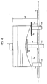
- the sheet feeding cassette 24 includes a frame member like tray body 4 having a handle section 2, a pair of side fences 6a and 6b slidably supported on the tray body 4, and an end fence 8 freely slidably supported by the tray body 4 at both front and the rear sides in the sheet feeding direction. Also included is a swingable bottom plate 10 supported by a pin on the tray body 4 at its base end to mount a stack of recording mediums. Further included is a cam structure arranged below the bottom plate 10 for pressurizing a leading end of a stack of recording mediums against a pick up roller, not shown.
- the bottom plate 10 is divided into three bottom plate pieces 10A to 10C in a sheet cassette widthwise direction. Each of these bottom plate pieces 10A to 10C is commonly attached to the tray body 4 by a supporting pin 11 as a swingable center at their base end, so that each of front sides thereof is upwardly movable around the supporting pin.
- a lifting device for upwardly moving the bottom plate includes a camshaft 12 and plural disc cams 13a to 13C secured and penetrated by the camshaft 12.
- the disk cams 13A to 13C each includes a prescribed shape corresponding to each of the bottom plate pieces 10A to 10C, wherein two of those (13A and 13C) are common.
- the camshaft 12 engages with a coupling of a gear-attached motor 9 as shown in FIG. 3 so that the bottom plate can be lifted.
- the disc cam 13 rotates as the camshaft 12 rotates, the bottom plate pieces change their rotation angles along the lines of the outer circumferential sections of respective disc cams (e.g. prescribed outlines) contacting a bottom plate.
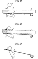
- FIG. 4 wherein a bottom plate is lifter and detected by a detection device.
- the detection device detects presence of the sheet cassette (the tray) in step S1
- the gear-attached motor 9 starts rotating and drives the disc cam 13 via the camshaft 12 and swings the bottom plate 10, so that the recording medium is lifted up.
- FIG. 4B illustrates a condition where the bottom plate 10 is lifted and the recording medium 21 is ready for sheet feeding.
- a sheet lifting operation an operation starting from when the cam shaft 12 rotates from the bottom plate lowermost position of FIG. 4A to when it stops in a condition as shown in FIG. 4B is called a sheet lifting operation.
- the driving device When the recording medium is conveyed to the image formation section, and the upper surface of the stack lowers, the driving device operates and lifts the bottomplate until the upper surface can be detected, because the upper surface detection device detects nothing. As far as the recording mediums remain on the bottom plate, lifting and non-lifting of the bottom plate are repeated. As shown in FIG. 4C , when no recording medium exists on the bottom plate, the second filler 27 slips into a detection hole 29 formed on the bottom plate and positions therebelow, and detects that the recording medium has gone from the bottom plate. Such an effect is then displayed on an operation section, not shown. When an operator attempts to withdraw the sheet cassette from the apparatus body, a coupling between the cam shaft 12 and the driving device disengages with the camshaft 12 of the sheet cassette, and the bottom plate returns by its gravity to the lowest position, so that the sheet cassette can be detached.
- the image forming apparatus controls the camshaft 12 to rotate so that the upper surface comes to the height Hsf.
- Hsf the height of the bottom plate
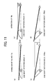
- the outline shape of the disc cams contacting and lifting the bottom plate pieces meets the following condition at the outer circumferential scuffing sections when the rotation angle of the camshaft theta ( ⁇ ) is zero, i.e., the bottom plate exists at the lowest position; Hb ⁇ 0 Height of the bottom plate piece 10 ⁇ B > Ha ⁇ 0 Height of the bottom plate pieces 10 ⁇ a , 10 ⁇ c
- the leading end height of the bottom plate piece 10b is higher than that of the leading end height of both sides of the bottom plate pieces 10a and 10c when the envelope like recording mediums are not stacked.
- a relation between the camshaft rotation angle theta ( ⁇ ) and the bottom plate height established from when the stack of the envelope like recording mediums is lifted to when the topmost recording medium bundle contacts and fed by the pickup roller is illustrated in FIG. 10 .
- Exemplary conditions of respective bottom plate pieces when the camshaft rotation angle is both zero and maximum are illustrated in FIG. 11 .
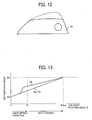
- FIG. 12 A relation between the camshaft rotation angle theta ( ⁇ ) and the bottom plate height established when the stack of the envelope like recording mediums is lifted and the topmost recording medium contacts and fed by the pickup roller while using the above-mentioned central bottom plate piece use cam is illustrated in FIG. 13 .
- Exemplary conditions of respective bottom plate pieces when the camshaft rotation angle is zero, and the sheet feed start time angle thetal ( ⁇ 1), as well as the maximum angle ( ⁇ max) are illustrated in FIG. 14 .
- the relation between the bottom plate angle and the bottom plate height shown in FIG. 2 can be appropriately changed in accordance with a type of the envelope like recording medium.
- the disc cam and the camshaft are used as a bottom plate-lifting device.
- the other lifting member can be employed as far as it includes an outline corresponding to a change in a thickness of an envelope like printing mediums.
- a curvature outline can be formed on an arm piece integral with the rotation shaft as mentioned later in detail with reference to FIG. 20 to correspond to the change of the thickness of the envelope like printing mediums.
- convex beads 14 are provided on the bottom plates 10a to 10c.
- confliction reduction members can be attached.
- convex beads can be provided on the rear side of the bottom plates 10a to 10c, i.e., on the side of the bottom plate-lifting device (i.e., cam) to reduce lifting between the bottom plate and the bottom plate elevation device.
- the convex beads 15 by arranging the convex beads 15 on the outer circumferential scuffing surface of the cam 13, scuffing confliction caused on the bottom plate is reduced.
- a miler (a name of commodity) sheet, a Teflon (TM) sheet and the like can be attached.
- the central bottom plate piece 10b' becomes sharp at a tip more than the base end.
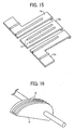
- the side end use bottom plate pieces 10a' and 10c' become wider toward their tips. With such a shape, when a curled radius of a stack of envelope like recording mediums is small, a close contact performance of the central bottom plate piece 10b'in relation to the central region of the stack can be improved.
- FIG. 18 Another modification of the division bottom plate piece combination of FIG. 18 shows a construction in that a rotational center of one of bottom plate pieces is differentiated from the above-mentioned modifications.
- the central bottom plate piece can be shorter.
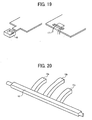
- FIG. 19 illustrates an attempt for simplifying an assembling operation for assembling a bottom plate and a sheet feed tray.
- one of a convex or concave section and a hole is formed on a bottom plate piece at its base end to fit into a concave piece 16 or a convex hook 17 formed on a tray body.
- the fitting section serves as a rotation center of the bottom plate.
- FIG. 20 illustrates an example, in which plural arm like curvature pieces 19a to 19c are provided integral with a rotation shaft 18, which is included in a bottom plate lifting device 18, to lift the bottom plate while scuffing the lower surface of the bottom plate.
- the plural arm like curvature pieces 19a to 19c are made of the same material such as iron, brass, aluminum, etc., and resin, ABS, POM, and PC resin.
- a curved outlines of the arm like curvature pieces correspond to changes in a thickness of each of corresponding positions of envelope like printing mediums.
- the outline shape of the outer circumferential scuffing section of the cam member for lifting the bottom plate is determined to uniquely change a bottom plate leading end as the bottom plate changes its rotation angle, and is thus different in accordance with a type of an envelope like recording medium.
- a process of the outline change is almost the same even when a type of recording medium is different and the thickness of the stack varies.
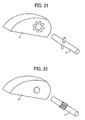
- a structure capable of changing a fitting position of a shaft fitting into a cam member in a rotation direction is changed as described with reference to FIG. 21 .
- a concave and convex section is formed around a shaft hole on a cam member 13' and engages with a pin section attached to the camshaft 127.
- a securing member such as an E-letter shaped ring, a stopping ring, etc.
- a fastening device can reduce a diameter of the hole of the cam member to prevent the shaft direction movement of the cam member 13'.
- a sprain state groove is formed on a shaft inner surface of the cam member" and is engaged with a sprain state groove formed on the surface of the cam shaft 12".
- a fixing member such as an E-letter shaped ring, a stopping ring, etc., prevents a shaft direction movement of the cam member 13' after engagement.
Landscapes
- Engineering & Computer Science (AREA)
- Mechanical Engineering (AREA)
- Sheets, Magazines, And Separation Thereof (AREA)
- Paper Feeding For Electrophotography (AREA)
Applications Claiming Priority (2)
| Application Number | Priority Date | Filing Date | Title |
|---|---|---|---|
| JP2008090535 | 2008-03-31 | ||
| JP2008329893A JP5187186B2 (ja) | 2008-03-31 | 2008-12-25 | 給紙トレイ構造及び画像形成装置 |
Publications (3)
| Publication Number | Publication Date |
|---|---|
| EP2107019A2 true EP2107019A2 (de) | 2009-10-07 |
| EP2107019A3 EP2107019A3 (de) | 2011-10-12 |
| EP2107019B1 EP2107019B1 (de) | 2012-10-10 |
Family
ID=40897340
Family Applications (1)
| Application Number | Title | Priority Date | Filing Date |
|---|---|---|---|
| EP09250911A Ceased EP2107019B1 (de) | 2008-03-31 | 2009-03-27 | Blattzuführungsablage und Bilderzeugungsvorrichtung |
Country Status (4)
| Country | Link |
|---|---|
| US (1) | US8074979B2 (de) |
| EP (1) | EP2107019B1 (de) |
| JP (1) | JP5187186B2 (de) |
| CN (1) | CN101549795B (de) |
Families Citing this family (9)
| Publication number | Priority date | Publication date | Assignee | Title |
|---|---|---|---|---|
| GB201001814D0 (en) * | 2010-02-04 | 2010-03-24 | Vivid Laminating Technologies | Feed mechanism for laminating machine |
| CN102408023A (zh) * | 2011-06-10 | 2012-04-11 | 刘安成 | 分纸斜 |
| JP5884518B2 (ja) * | 2012-01-31 | 2016-03-15 | コニカミノルタ株式会社 | 給紙装置及び画像形成装置 |
| US8827262B2 (en) * | 2012-07-19 | 2014-09-09 | Canon Kabushiki Kaisha | Sheet feeding apparatus and image forming apparatus |
| CN102837500A (zh) * | 2012-09-27 | 2012-12-26 | 珠海天威飞马打印耗材有限公司 | 平板打印机 |
| JP6398474B2 (ja) | 2014-08-29 | 2018-10-03 | ブラザー工業株式会社 | シート収容装置および画像形成装置 |
| JP6515865B2 (ja) * | 2016-04-28 | 2019-05-22 | 京セラドキュメントソリューションズ株式会社 | ペーパーカセットの緩衝材、及びペーパーカセットの梱包方法 |
| JP7363155B2 (ja) * | 2019-07-22 | 2023-10-18 | 京セラドキュメントソリューションズ株式会社 | シートカセット、画像形成装置 |
| JP2024107994A (ja) * | 2023-01-30 | 2024-08-09 | 京セラドキュメントソリューションズ株式会社 | 用紙後処理装置、及び画像形成システム |
Citations (1)
| Publication number | Priority date | Publication date | Assignee | Title |
|---|---|---|---|---|
| JP3542689B2 (ja) | 1996-07-25 | 2004-07-14 | 株式会社湯山製作所 | 薬袋フィーダ |
Family Cites Families (14)
| Publication number | Priority date | Publication date | Assignee | Title |
|---|---|---|---|---|
| JPS5827233U (ja) * | 1981-08-19 | 1983-02-22 | ユ−ザツク電子工業株式会社 | 自動給紙装置の用紙積載板 |
| JPS61132332U (de) * | 1985-02-05 | 1986-08-18 | ||
| JPH0479832A (ja) * | 1990-07-22 | 1992-03-13 | Dowa:Kk | 火焔噴射装置 |
| JPH04179632A (ja) * | 1990-11-13 | 1992-06-26 | Mita Ind Co Ltd | 給紙カセット |
| JPH05270667A (ja) * | 1992-03-30 | 1993-10-19 | Ricoh Co Ltd | 給紙装置 |
| JPH07247029A (ja) * | 1994-03-08 | 1995-09-26 | Riso Kagaku Corp | 給紙装置 |
| JP3006845U (ja) * | 1994-07-18 | 1995-01-31 | 船井電機株式会社 | 給紙カセット |
| JPH08259002A (ja) * | 1995-03-22 | 1996-10-08 | Tec Corp | 給紙装置 |
| JPH107265A (ja) | 1996-06-20 | 1998-01-13 | Ricoh Co Ltd | 給紙圧調整装置 |
| JP3718954B2 (ja) * | 1997-04-28 | 2005-11-24 | 松下電器産業株式会社 | 給紙装置 |
| JP3771365B2 (ja) * | 1997-12-25 | 2006-04-26 | 株式会社湯山製作所 | 薬袋フィーダ |
| JP3049024B1 (ja) * | 1998-11-19 | 2000-06-05 | 日本電気オフィスシステム株式会社 | 印刷装置の用紙供給部 |
| DE29903717U1 (de) * | 1999-03-02 | 1999-06-24 | Océ Printing Systems GmbH, 85586 Poing | Vorrichtung zur Bereitstellung eines Vorrats von Einzelblättern ungleicher Dicke |
| JP2001348125A (ja) * | 2000-06-09 | 2001-12-18 | Dainippon Printing Co Ltd | 刷本供給装置 |
-
2008
- 2008-12-25 JP JP2008329893A patent/JP5187186B2/ja not_active Expired - Fee Related
-
2009
- 2009-03-27 EP EP09250911A patent/EP2107019B1/de not_active Ceased
- 2009-03-30 US US12/385,043 patent/US8074979B2/en not_active Expired - Fee Related
- 2009-03-31 CN CN2009101305152A patent/CN101549795B/zh not_active Expired - Fee Related
Patent Citations (1)
| Publication number | Priority date | Publication date | Assignee | Title |
|---|---|---|---|---|
| JP3542689B2 (ja) | 1996-07-25 | 2004-07-14 | 株式会社湯山製作所 | 薬袋フィーダ |
Also Published As
| Publication number | Publication date |
|---|---|
| EP2107019A3 (de) | 2011-10-12 |
| JP5187186B2 (ja) | 2013-04-24 |
| EP2107019B1 (de) | 2012-10-10 |
| JP2009263133A (ja) | 2009-11-12 |
| US20090243196A1 (en) | 2009-10-01 |
| CN101549795A (zh) | 2009-10-07 |
| US8074979B2 (en) | 2011-12-13 |
| CN101549795B (zh) | 2011-11-02 |
Similar Documents
| Publication | Publication Date | Title |
|---|---|---|
| EP2107019B1 (de) | Blattzuführungsablage und Bilderzeugungsvorrichtung | |
| US5803705A (en) | Disk type inverter-stacker with improved sheet handling slots for different paper weights | |
| JP2005238828A (ja) | シート束背面折り部平坦処理装置、シート処理装置、及び画像形成装置 | |
| JP6324074B2 (ja) | シート積載装置、シート給送装置及び画像形成装置 | |
| US6302389B1 (en) | Sheet treating apparatus and image forming apparatus having the same | |
| US20160257511A1 (en) | Sheet feeder, image reading apparatus, and image forming apparatus | |
| JP4777211B2 (ja) | シート給送装置及び画像形成装置 | |
| US8827262B2 (en) | Sheet feeding apparatus and image forming apparatus | |
| JP4880530B2 (ja) | 被記録媒体給送装置、及び画像形成装置 | |
| US12252368B2 (en) | Sheet feeding apparatus and image forming apparatus | |
| US10351369B2 (en) | Sheet stacking apparatus, sheet feeding apparatus, image forming apparatus, and image forming system | |
| JP3825331B2 (ja) | 給紙装置および画像形成装置 | |
| JP3744706B2 (ja) | 画像形成装置 | |
| JP4495876B2 (ja) | 給紙装置および画像形成装置 | |
| JP4067941B2 (ja) | シート材の給送方法と給送装置及びそれを備えた画像形成装置 | |
| JPH1035927A (ja) | シート給送装置及びシート処理装置 | |
| JP2004026493A (ja) | 給送装置とそれを備えた画像形成装置及びシート材の給送方法 | |
| JP2001106345A (ja) | シート供給装置及びこの装置を備えた画像形成装置 | |
| JP3828037B2 (ja) | シート材の給送方法とその装置及びそれを備えた画像形成装置 | |
| JP2026022120A (ja) | ローラユニットおよび画像形成装置 | |
| JP2001213529A (ja) | シート及びタブ紙収納装置とこの装置を備えた画像形成装置 | |
| JP2000143002A (ja) | シート給送装置及び該装置を備えた画像形成装置 | |
| JP2000302258A (ja) | シート材給送装置及び画像形成装置 | |
| JP3648832B2 (ja) | 給紙装置及びこれを用いた印刷装置 | |
| JP2001048362A (ja) | シート供給装置及びこれを備える画像形成装置 |
Legal Events
| Date | Code | Title | Description |
|---|---|---|---|
| PUAI | Public reference made under article 153(3) epc to a published international application that has entered the european phase |
Free format text: ORIGINAL CODE: 0009012 |
|
| AK | Designated contracting states |
Kind code of ref document: A2 Designated state(s): AT BE BG CH CY CZ DE DK EE ES FI FR GB GR HR HU IE IS IT LI LT LU LV MC MK MT NL NO PL PT RO SE SI SK TR |
|
| AX | Request for extension of the european patent |
Extension state: AL BA RS |
|
| PUAL | Search report despatched |
Free format text: ORIGINAL CODE: 0009013 |
|
| AK | Designated contracting states |
Kind code of ref document: A3 Designated state(s): AT BE BG CH CY CZ DE DK EE ES FI FR GB GR HR HU IE IS IT LI LT LU LV MC MK MT NL NO PL PT RO SE SI SK TR |
|
| AX | Request for extension of the european patent |
Extension state: AL BA RS |
|
| RIC1 | Information provided on ipc code assigned before grant |
Ipc: B65H 1/14 20060101AFI20110908BHEP |
|
| 17P | Request for examination filed |
Effective date: 20120217 |
|
| GRAP | Despatch of communication of intention to grant a patent |
Free format text: ORIGINAL CODE: EPIDOSNIGR1 |
|
| AKX | Designation fees paid |
Designated state(s): DE FR GB |
|
| GRAS | Grant fee paid |
Free format text: ORIGINAL CODE: EPIDOSNIGR3 |
|
| GRAA | (expected) grant |
Free format text: ORIGINAL CODE: 0009210 |
|
| AK | Designated contracting states |
Kind code of ref document: B1 Designated state(s): DE FR GB |
|
| REG | Reference to a national code |
Ref country code: GB Ref legal event code: FG4D |
|
| REG | Reference to a national code |
Ref country code: DE Ref legal event code: R096 Ref document number: 602009010319 Country of ref document: DE Effective date: 20121206 |
|
| PLBE | No opposition filed within time limit |
Free format text: ORIGINAL CODE: 0009261 |
|
| STAA | Information on the status of an ep patent application or granted ep patent |
Free format text: STATUS: NO OPPOSITION FILED WITHIN TIME LIMIT |
|
| 26N | No opposition filed |
Effective date: 20130711 |
|
| REG | Reference to a national code |
Ref country code: DE Ref legal event code: R097 Ref document number: 602009010319 Country of ref document: DE Effective date: 20130711 |
|
| REG | Reference to a national code |
Ref country code: FR Ref legal event code: PLFP Year of fee payment: 8 |
|
| REG | Reference to a national code |
Ref country code: FR Ref legal event code: PLFP Year of fee payment: 9 |
|
| REG | Reference to a national code |
Ref country code: FR Ref legal event code: PLFP Year of fee payment: 10 |
|
| PGFP | Annual fee paid to national office [announced via postgrant information from national office to epo] |
Ref country code: DE Payment date: 20180322 Year of fee payment: 10 Ref country code: GB Payment date: 20180321 Year of fee payment: 10 |
|
| PGFP | Annual fee paid to national office [announced via postgrant information from national office to epo] |
Ref country code: FR Payment date: 20180330 Year of fee payment: 10 |
|
| REG | Reference to a national code |
Ref country code: DE Ref legal event code: R119 Ref document number: 602009010319 Country of ref document: DE |
|
| GBPC | Gb: european patent ceased through non-payment of renewal fee |
Effective date: 20190327 |
|
| PG25 | Lapsed in a contracting state [announced via postgrant information from national office to epo] |
Ref country code: DE Free format text: LAPSE BECAUSE OF NON-PAYMENT OF DUE FEES Effective date: 20191001 Ref country code: GB Free format text: LAPSE BECAUSE OF NON-PAYMENT OF DUE FEES Effective date: 20190327 |
|
| PG25 | Lapsed in a contracting state [announced via postgrant information from national office to epo] |
Ref country code: FR Free format text: LAPSE BECAUSE OF NON-PAYMENT OF DUE FEES Effective date: 20190331 |