EP2105383B2 - Verpackungsmaschine - Google Patents
Verpackungsmaschine Download PDFInfo
- Publication number
- EP2105383B2 EP2105383B2 EP08020942.2A EP08020942A EP2105383B2 EP 2105383 B2 EP2105383 B2 EP 2105383B2 EP 08020942 A EP08020942 A EP 08020942A EP 2105383 B2 EP2105383 B2 EP 2105383B2
- Authority
- EP
- European Patent Office
- Prior art keywords
- cover
- lid
- chamber
- joint
- vacuum chamber
- Prior art date
- Legal status (The legal status is an assumption and is not a legal conclusion. Google has not performed a legal analysis and makes no representation as to the accuracy of the status listed.)
- Not-in-force
Links
Images


Classifications
-
- B—PERFORMING OPERATIONS; TRANSPORTING
- B65—CONVEYING; PACKING; STORING; HANDLING THIN OR FILAMENTARY MATERIAL
- B65B—MACHINES, APPARATUS OR DEVICES FOR, OR METHODS OF, PACKAGING ARTICLES OR MATERIALS; UNPACKING
- B65B31/00—Packaging articles or materials under special atmospheric or gaseous conditions; Adding propellants to aerosol containers
- B65B31/02—Filling, closing, or filling and closing, containers or wrappers in chambers maintained under vacuum or superatmospheric pressure or containing a special atmosphere, e.g. of inert gas
- B65B31/024—Filling, closing, or filling and closing, containers or wrappers in chambers maintained under vacuum or superatmospheric pressure or containing a special atmosphere, e.g. of inert gas specially adapted for wrappers or bags
-
- B—PERFORMING OPERATIONS; TRANSPORTING
- B65—CONVEYING; PACKING; STORING; HANDLING THIN OR FILAMENTARY MATERIAL
- B65B—MACHINES, APPARATUS OR DEVICES FOR, OR METHODS OF, PACKAGING ARTICLES OR MATERIALS; UNPACKING
- B65B59/00—Arrangements to enable machines to handle articles of different sizes, to produce packages of different sizes, to vary the contents of packages, to handle different types of packaging material, or to give access for cleaning or maintenance purposes
- B65B59/04—Machines constructed with readily-detachable units or assemblies, e.g. to facilitate maintenance
Definitions
- the present invention relates to a packaging machine, in particular a chamber belt machine.
- the chamber lid of the vacuum chamber can only be moved vertically, making it difficult for service personnel to clean the interior of the lid or to perform maintenance or repair work. Between the machine frame and the lower edge of the lid there is usually only a 300mm gap available for this work. Due to this limited accessibility, the work can only be carried out with limited or increased effort. The accessibility and the visibility of the inside of the lid during maintenance, repair or cleaning work is difficult. From an ergonomic point of view, this work is a heavy burden for the service technician or the cleaning staff.
- a packaging machine according to the preamble of claim 1 is known from US 3,818,574 out.
- a packaging machine with a vacuum chamber, which is rotatable as a whole, is in the WO 01/94209 A1 described.
- the US 5,465,557 A finally discloses a vacuum chamber for a packaging machine, the lid is pivotable about a hinge.
- the object of the present invention is to provide a packaging machine which improves the ergonomic accessibility and the visibility of the inside of the lid of a vacuum chamber of a packaging machine for maintenance, repair or cleaning work.
- the object is achieved by a packaging machine according to claim 1.
- the inventive pivotability of the lid, the ergonomic accessibility and the visibility of the lid interior is improved. Maintenance, repair or cleaning work can be carried out in front of the machine by a service technician or cleaning staff. This is particularly important in the field of food packaging or in the packaging of medical-sterile goods, since strict legal hygiene regulations must be observed.
- the chamber belt machine is designed as an automatic chamber belt machine.
- Fig. 1 shows a schematic view of a chamber belt machine with a conveyor belt 1, a frame 2, a laying area 3, a vacuum chamber 4 and a lid 5.
- the chamber 4 is formed by the lid 5 together with a part of the conveyor belt 1, wherein the cover 5 motor operated pneumatically or hydraulically operated opens automatically or power-operated, or open manually, for example, to be evacuated or sealed bags that are automatically fed by the conveyor belt 2, and then automatically closes to form the chamber 4.
- the lid 5 is composed of a top surface, two side surfaces and two end surfaces.
- the cover 5 In Fig. 1 the cover 5 is in its horizontal working position or in its lowered relative to the conveyor belt position in which the top surface of the lid 5 is aligned parallel to the conveyor belt 1. In this position, the chamber 4 is closed.
- Fig. 2a, b shows the chamber belt machine in perspective view and in front view.
- the lid 5 is in its horizontal working position. It is provided a lifting device 6, which allows a vertical lifting movement, ie orthogonal to the conveyor belt 1, the lid 5 in a raised position in which the chamber 4 is opened.
- the lifting device 6 is a linear guide which is fixed on both sides of the conveyor belt 1 on the frame 2.
- the movable parts of the linear guide, which are intended to realize the vertical stroke of the cover 5, are connected to one another via a transverse strut 8.
- the cover 5 is articulated to this cross member 8 and articulated there with a centrally mounted joint 7. In this way, the lid 5 in addition to the vertical translational movement also perform a rotational movement about the hinge axis.
- the axis of rotation passes through the center of gravity of the two end faces of the lid 5, to a smooth pivoting of the lid 5 to guarantee.
- the cover 5 is connected to the hinge 7 in such a way that the axis of rotation passes through the center of mass of the cover 5 and parallel to the two lower edges of the side surfaces.
- Fig. 3a, b shows the chamber belt machine in perspective or in front view.
- the lid 5 is located in a vertical maintenance, repair or cleaning position or in a raised and pivoted position, hereinafter referred to as maintenance position.
- the side surfaces of the lid 5 are in this position parallel to the conveyor belt 1. It extends here in each case substantially half of the end faces and the side surfaces of the lid 5 above and below the cross member. 8
- the lid 5 In operation, the lid 5 from its working position (see Fig. 2a, b ) to its maintenance position ( Fig. 3a, b ), to perform maintenance, repair or cleaning work inside the lid.
- the lid 5 is first translated translationally above the lifting device 6 in the vertical direction. Due to the articulated connection of the cover 5 with the transverse strut 8 or with the joint 7, the cover 5 can be pivoted after this lifting movement into a vertical maintenance position. In this position, the interior of the lid is optimally accessible or visible.
- the cover 5 In order to transfer the cover 5 from the maintenance position back to the working position, the cover 5 is pivoted back about its axis of rotation and then brought over the lifting device 6 in its working position.
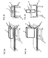
- Fig. 4.5 show a non-inventive embodiment of the present invention.
- the joint 7 is mounted eccentrically on the crossbar 8.
- the lid 5 is accordingly also off-center connected to the hinge 7 in order to ensure a correct position of the lid 5 on the conveyor belt 1.
- Fig. 4 is the lid 5 in a raised position, after the lifting movement but before the pivotal movement of the lid 5.
- Fig. 5 is the lid 5 in its maintenance position. Due to the eccentric mounting of the lid 5 only a small lifting movement of the lifting device 6 is necessary to move the cover 5 from its working position to its maintenance position, since in the maintenance position, the largest part of the lid 5 extends above the cross strut 8.
- an auxiliary device 9 for example in the form of a gas spring or a pneumatic cylinder, is provided to ensure optimum operability and smooth pivoting of the lid 5.
- One end of the auxiliary device 9 is attached to the cover 5, the other end to the crossbar 8.
Description
- Die vorliegende Erfindung bezieht sich auf eine Verpackungsmaschine, insbesondere eine Kammerbandmaschine.
- Bei Verpackungsmaschinen werden hohe Anforderungen an die Reinigbarkeit und die Servicefreundlichkeit gestellt. Bei automatisierten Vakuumverpackungsmaschinen, beispielsweise bei Kammerbandmaschinen im oberen Leistungsbereich, kann der Kammerdeckel der Vakuumkammer nur vertikal bewegt werden, was es für Reinigungs- bzw. Servicepersonal schwierig macht, das Innere des Deckels zu reinigen bzw. Wartungs- oder Reparaturarbeiten durchzuführen. Zwischen dem Maschinengestell und der Deckelunterkante steht für diese Arbeiten in der Regel nur ein ca. 300mm hoher Spalt zur Verfügung. Durch diese begrenzte Zugänglichkeit kann die Arbeit nur eingeschränkt oder unter erhöhtem Aufwand durchgeführt werden. Die Erreichbarkeit und die Einsehbarkeit des Deckelinneren bei Wartungs-, Reparatur- oder Reinigungsarbeiten ist erschwert. Aus ergonomischen Gesichtspunkten sind diese Arbeiten eine hohe Belastung für den Servicetechniker bzw. das Reinigungspersonal.
- Eine Verpackungsmaschine gemäß dem Oberbegriff des Anspruchs 1 geht aus der
US 3,818,574 hervor. Eine Verpackungsmaschine mit einer Vakuumkammer, die als Ganzes rotierbar ist, ist in derWO 01/94209 A1 US 5,465,557 A offenbart schließlich eine Vakuumkammer für eine Verpackungsmaschine, deren Deckel um ein Scharnier schwenkbar ist. - Die Aufgabe der vorliegenden Erfindung ist es, eine Verpackungsmaschine bereitzustellen, die die ergonomische Zugänglichkeit und die Einsehbarkeit des Deckelinneren einer Vakuumkammer einer Verpackungsmaschine für Wartungs-, Reparatur oder Reinigungsarbeiten verbessert. Die Aufgabe wird gelöst durch eine Verpackungsmaschine gemäß Anspruch 1.
- Durch die erfindungsgemäße Schwenkbarkeit des Deckels wird die ergonomische Erreichbarkeit und die Einsehbarkeit des Deckelinneren verbessert. Wartungs-, Reparatur- oder Reinigungsarbeiten können auf diese Weise von einem Servicetechniker oder Reinigungspersonal stehend vor der Maschine durchgeführt werden. Dies ist insbesondere im Bereich der Lebensmittelverpackung bzw. beim Verpacken von medizinisch-sterilen Gütern unerlässlich, da hier strenge gesetzliche Hygienevorschriften zu beachten sind.
- Weitere Merkmale und Zweckmäßigkeiten der Erfindung ergeben sich aus der Beschreibung eines Ausführungsbeispiels anhand der beigefügten Zeichnungen. Von den Figuren zeigen:
- Fig. 1
- eine schematische Ansicht einer Kammerbandmaschine;
- Fig. 2a
- eine schematische perspektivische Ansicht einer Kammerbandmaschine mit geschlossenem Deckel nach einer ersten Ausführungsform;
- Fig. 2b
- eine schematische Vorderansicht einer Kammerbandmaschine mit geschlossenem Deckel nach einer ersten Ausführungsform;
- Fig. 3a
- eine schematische perspektivische Ansicht einer Kammerbandmaschine mit geöffnetem Deckel nach einer ersten Ausführungsform;
- Fig. 3b
- eine schematische Vorderansicht einer Kammerbandmaschine mit geöffnetem Deckel nach einer ersten Ausführungsform;
- Fig. 4
- eine schematische Vorderansicht einer Kammerbandmaschine mit geschlossenem Deckel nach einer nicht erfindungsgemäßen Ausführungsform;
- Fig. 5
- eine schematische Vorderansicht einer Kammerbandmaschine mit geöffnetem Deckel nach einer nicht erfindungsgemäßen Ausführungsform.
- Im Folgenden wird mit Bezug auf
Fig. 1 ,2a, 2b, 3a und 3b eine Ausführungsform der vorliegenden Erfindung beispielhaft an einer Kammerbandmaschine beschrieben. In der vorliegenden Ausführungsform ist die Kammerbandmaschine als automatische Kammerbandmaschine ausgebildet. -
Fig. 1 zeigt eine schematische Ansicht einer Kammerbandmaschine mit einem Förderband 1, einem Gestell 2, einem Auflegebereich 3, einer Vakuumkammer 4 und einem Deckel 5. Die Kammer 4 wird durch den Deckel 5 zusammen mit einem Teil des Förderbands 1 gebildet, wobei sich der Deckel 5 motorisch, pneumatisch oder hydraulisch betrieben automatisch bzw. kraftbetätigt gesteuert öffnet oder manuell öffnen lässt, um beispielsweise zu evakuierende bzw. zu versiegelnde Beutel aufzunehmen, die durch das Förderband 2 automatisch zugeführt werden, und der sich anschließend automatisch schließt, um die Kammer 4 zu bilden. - Der Deckel 5 setzt sich aus einer Deckfläche, zwei Seitenflächen und zwei Stirnflächen zusammen. In
Fig. 1 befindet sich der Deckel 5 in seiner horizontalen Arbeitsposition bzw. in seiner relativ zum Förderband abgesenkten Position, in der die Deckfläche des Deckels 5 parallel zum Förderband 1 ausgerichtet ist. In dieser Position ist die Kammer 4 geschlossen. -
Fig. 2a,b zeigt die Kammerbandmaschine in perspektivischer Ansicht bzw. in Vorderansicht. Der Deckel 5 befindet sich in seiner horizontalen Arbeitsposition. Es ist eine Hubvorrichtung 6 vorgesehen, die eine vertikale Hubbewegung, also orthogonal zum Förderband 1, des Deckels 5 in eine angehobene Position ermöglicht, in der die Kammer 4 geöffnet ist. Die Hubvorrichtung 6 ist eine Linearführung, die auf beiden Seiten des Förderbands 1 am Gestell 2 befestigt ist. Die bewegbaren Teile der Linearführung, die den Vertikalhub des Deckels 5 realisieren sollen, sind über eine Querstrebe 8 miteinander verbunden. Der Deckel 5 ist gelenkig mit dieser Querstrebe 8 bzw. mit einem dort mittig angebrachten Gelenk 7 gelenkig verbunden. Auf diese Weise kann der Deckel 5 neben der vertikalen Translationsbewegung auch eine Rotationsbewegung um die Gelenkachse durchführen. Die Rotationsachse verläuft durch die Flächenschwerpunkte der beiden Stirnflächen des Deckels 5, um ein leichtgängiges Schwenken des Deckels 5 zu gewährleisten. Bei der Erfindung ist der Deckel 5 derart mit dem Gelenk 7 verbunden, dass die Rotationsachse durch den Massenschwerpunkt des Deckels 5 und parallel zu den beiden Unterkanten der Seitenflächen verläuft. -
Fig. 3a,b zeigt die Kammerbandmaschine in perspektivischer bzw. in Vorderansicht. Der Deckel 5 befindet sich in einer vertikalen Wartungs-, Reparatur- bzw. Reinigungsposition bzw. in einer angehobenen und geschwenkten Position, im folgenden als Wartungsposition bezeichnet. Die Seitenflächen des Deckels 5 sind in dieser Position parallel zum Förderband 1. Es erstreckt sich hierbei im wesentlichen jeweils die Hälfte der Stirnflächen und der Seitenflächen des Deckels 5 oberhalb und unterhalb der Querstrebe 8. - Im Betrieb wird der Deckel 5 aus seiner Arbeitsposition (siehe
Fig. 2a,b ) in seine Wartungsposition (Fig. 3a,b ), gebracht, um im Deckelinneren Wartungs-, Reparatur- oder Reinigungsarbeiten durchzuführen. Hierfür wird der Deckel 5 zunächst über die Hubvorrichtung 6 in vertikaler Richtung translatorisch nach oben verschoben. Durch die gelenkige Verbindung des Deckels 5 mit der Querstrebe 8 bzw. mit dem Gelenk 7 kann der Deckel 5 nach dieser Hubbewegung in eine vertikale Wartungsposition geschwenkt werden. In dieser Position ist das Deckelinnere optimal erreichbar bzw, einsehbar. Um den Deckel 5 aus der Wartungsposition wieder in die Arbeitsposition zu überführen, wird der Deckel 5 um seine Rotationsachse zurückgeschwenkt und danach über die Hubvorrichtung 6 in seine Arbeitsposition gebracht. -
Fig. 4,5 zeigen eine nicht erfindungsgemäße Ausführungsform der vorliegenden Erfindung. Das Gelenk 7 ist außermittig auf der Querstrebe 8 angebracht. Der Deckel 5 ist dementsprechend ebenfalls außermittig mit dem Gelenk 7 verbunden, um eine korrekte Position des Deckels 5 über dem Förderband 1 zu gewährleisten. InFig. 4 befindet sich der Deckel 5 auf einer angehobenen Position, nach der Hubbewegung aber noch vor der Schwenkbewegung des Deckels 5. InFig. 5 befindet sich der Deckel 5 in seiner Wartungsposition. Durch die außermittige Anbringung des Deckels 5 ist nur eine geringe Hubbewegung der Hubvorrichtung 6 notwendig, um den Deckel 5 aus seiner Arbeitsposition in seine Wartungsposition zu bewegen, da sich in der Wartungsposition der größte Teil des Deckels 5 oberhalb der Querstrebe 8 erstreckt. - Da die Rotations- bzw. Schwenkachse des Deckels 5 nicht mehr durch seinen Schwerpunkt verläuft, ist eine Hilfsvorrichtung 9, beispielsweise in Form einer Gasdruckfeder oder eines Pneumatikzylinders, vorgesehen, um eine optimale Bedienbarkeit bzw. ein leichtgängiges Schwenken des Deckels 5 zu gewährleisten. Ein Ende der Hilfsvorrichtung 9 ist am Deckel 5, das andere Ende an der Querstrebe 8 angebracht.
Claims (1)
- Verpackungsmaschine mit einem Förderband (1), einem Gestell (2) und einer Vakuumkammer (4), wobei die Vakuumkammer (4) einen Deckel (5) aufweist, der zwei Seitenflächen aufweist und durch eine vertikale Translationsbewegung von einer abgesenkten Position, in der die Vakuumkammer (4) geschlossen ist, anhebbar ist in eine angehobene Position, in der die Vakuumkammer (4) geöffnet ist, wobei die Verpackungsmaschine als Kammerbandmaschine ausgebildet ist, bei der der Deckel (5) zusammen mit einem Teil eines Förderbands (1) die Vakuumkammer (4) bildet, dadurch gekennzeichnet, dass der Deckel (5) in der angehobenen Position schwenkbar ist, und dass der Deckel (5) mit Hilfe einer Hubvorrichtung (6) anhebbar und absenkbar ist, wobei die Hubvorrichtung (6) eine Linearführung ist, die auf beiden Seiten des Förderbands (1) am Gestell (2) befestigt ist, wobei bewegbare Teile der Linearführung, die den Vertikalhub des Deckels (5) realisieren, über eine Querstrebe (8) miteinander verbunden sind,
wobei an der Querstrebe (8) ein Gelenk (7) angebracht ist, um das der Deckel (5) schwenkbar ist,
wobei das Gelenk (7) mittig an der Querstrebe (8) angebracht ist und der Deckel (5) derart mit dem Gelenk (7) verbunden ist, dass die Rotationsachse des Gelenks (7) durch den Massenschwerpunkt des Deckels (5) und parallel zu den beiden Unterkanten der Seitenflächen des Deckels (5) verläuft.
Applications Claiming Priority (1)
| Application Number | Priority Date | Filing Date | Title |
|---|---|---|---|
| DE102008015689A DE102008015689A1 (de) | 2008-03-26 | 2008-03-26 | Verpackungsmaschine |
Publications (3)
| Publication Number | Publication Date |
|---|---|
| EP2105383A1 EP2105383A1 (de) | 2009-09-30 |
| EP2105383B1 EP2105383B1 (de) | 2011-05-25 |
| EP2105383B2 true EP2105383B2 (de) | 2016-03-16 |
Family
ID=40338232
Family Applications (1)
| Application Number | Title | Priority Date | Filing Date |
|---|---|---|---|
| EP08020942.2A Not-in-force EP2105383B2 (de) | 2008-03-26 | 2008-12-03 | Verpackungsmaschine |
Country Status (5)
| Country | Link |
|---|---|
| US (1) | US8276352B2 (de) |
| EP (1) | EP2105383B2 (de) |
| AT (1) | ATE510773T1 (de) |
| DE (1) | DE102008015689A1 (de) |
| ES (1) | ES2363721T5 (de) |
Families Citing this family (16)
| Publication number | Priority date | Publication date | Assignee | Title |
|---|---|---|---|---|
| AU2004100000A4 (en) | 2004-01-02 | 2004-02-12 | Sands Innovations Pty Ltd | Dispensing stirring implement |
| CN101600633A (zh) | 2007-01-31 | 2009-12-09 | 桑德斯创新有限公司 | 分发器具及其制造方法 |
| AU2008365185B2 (en) | 2008-12-09 | 2016-05-05 | Sands Innovations Pty Ltd | A dispensing container |
| USD636890S1 (en) | 2009-09-17 | 2011-04-26 | Sands Innovations Pty. Ltd. | Dispensing utensil |
| DE102010013889A1 (de) * | 2010-04-07 | 2011-10-13 | Multivac Sepp Haggenmüller Gmbh & Co. Kg | Einrichtung für Kammerbandmaschine |
| DE102010019729A1 (de) | 2010-05-07 | 2011-11-10 | Multivac Sepp Haggenmüller Gmbh & Co. Kg | Arbeitsstation für Verpackungsmaschine |
| US8511500B2 (en) | 2010-06-07 | 2013-08-20 | Sands Innovations Pty. Ltd. | Dispensing container |
| US8485360B2 (en) | 2011-03-04 | 2013-07-16 | Sands Innovations Pty, Ltd. | Fracturable container |
| JP5946340B2 (ja) * | 2012-07-06 | 2016-07-06 | 株式会社古川製作所 | ベルト式真空包装機 |
| EP2733076A1 (de) * | 2012-11-15 | 2014-05-21 | Tetra Laval Holdings & Finance S.A. | Vorrichtung und Verfahren zum Versiegeln und Einschrumpfen einer in eine Schrumpffolie eingewickelten Mehrfachverpackung |
| EP2746168A1 (de) | 2012-12-21 | 2014-06-25 | Multivac Sepp Haggenmüller GmbH & Co. KG | Doppelkammerverpackungsmaschine mit schwenkbarem Kammerdeckel |
| EP2829479A1 (de) * | 2013-07-23 | 2015-01-28 | Cryovac, Inc. | Verpackungsvorrichtung mit Aktuator und Verfahren zum Betrieb einer Verpackungsvorrichtung |
| DE102014104387A1 (de) * | 2014-03-28 | 2015-10-01 | Textor Maschinenbau GmbH | Vorrichtung zur Verarbeitung von Lebensmittelprodukten |
| EP3439973A1 (de) * | 2016-04-07 | 2019-02-13 | GEA Food Solutions Germany GmbH | Verpackungsmaschine mit einem schwenkbaren oberteil |
| ES2733449T3 (es) | 2016-04-12 | 2019-11-29 | Webomatic Maschf Gmbh | Dispositivo para el envasado de productos alimenticios |
| US10954014B2 (en) * | 2016-06-09 | 2021-03-23 | Alkar-Rapidpak, Inc. | Lifting assemblies for assisting movement of die boxes on web packaging machines |
Citations (5)
| Publication number | Priority date | Publication date | Assignee | Title |
|---|---|---|---|---|
| US3397508A (en) † | 1965-08-06 | 1968-08-20 | Total Packaging Inc | Thermoplastic packaging machine |
| WO1995029846A1 (de) † | 1994-05-03 | 1995-11-09 | Inauen Maschinen Ag | Vakuum-verpackungsmaschine |
| US6050446A (en) † | 1997-07-11 | 2000-04-18 | Applied Materials, Inc. | Pivoting lid assembly for a chamber |
| WO2007090571A2 (de) † | 2006-02-09 | 2007-08-16 | Cfs Germany Gmbh | Siegelstation einer verpackungsmaschine |
| DE102006006220A1 (de) † | 2006-02-09 | 2007-08-16 | Cfs Germany Gmbh | Verpackungsmaschine mit einem Rahmen |
Family Cites Families (5)
| Publication number | Priority date | Publication date | Assignee | Title |
|---|---|---|---|---|
| US3818574A (en) | 1970-12-14 | 1974-06-25 | Grace W R & Co | Closing system for bags and the like |
| US5465557A (en) | 1994-06-09 | 1995-11-14 | Koch Supplies, Inc. | Hinge assembly for vacuum packaging machine |
| WO2001094209A1 (en) | 2000-06-05 | 2001-12-13 | Koch Equipment Llc | Rotating vacuum packaging apparatus |
| US6454115B1 (en) * | 2000-10-23 | 2002-09-24 | Cindy Chwang Allasia | Container construction |
| DE10238482A1 (de) * | 2002-05-23 | 2003-12-04 | Cfs Kempten Gmbh | Einlegevorrichtung |
-
2008
- 2008-03-26 DE DE102008015689A patent/DE102008015689A1/de not_active Withdrawn
- 2008-12-03 AT AT08020942T patent/ATE510773T1/de active
- 2008-12-03 EP EP08020942.2A patent/EP2105383B2/de not_active Not-in-force
- 2008-12-03 ES ES08020942.2T patent/ES2363721T5/es active Active
-
2009
- 2009-02-18 US US12/378,623 patent/US8276352B2/en not_active Expired - Fee Related
Patent Citations (5)
| Publication number | Priority date | Publication date | Assignee | Title |
|---|---|---|---|---|
| US3397508A (en) † | 1965-08-06 | 1968-08-20 | Total Packaging Inc | Thermoplastic packaging machine |
| WO1995029846A1 (de) † | 1994-05-03 | 1995-11-09 | Inauen Maschinen Ag | Vakuum-verpackungsmaschine |
| US6050446A (en) † | 1997-07-11 | 2000-04-18 | Applied Materials, Inc. | Pivoting lid assembly for a chamber |
| WO2007090571A2 (de) † | 2006-02-09 | 2007-08-16 | Cfs Germany Gmbh | Siegelstation einer verpackungsmaschine |
| DE102006006220A1 (de) † | 2006-02-09 | 2007-08-16 | Cfs Germany Gmbh | Verpackungsmaschine mit einem Rahmen |
Also Published As
| Publication number | Publication date |
|---|---|
| ATE510773T1 (de) | 2011-06-15 |
| EP2105383B1 (de) | 2011-05-25 |
| ES2363721T3 (es) | 2011-08-12 |
| DE102008015689A1 (de) | 2009-10-01 |
| US8276352B2 (en) | 2012-10-02 |
| ES2363721T5 (es) | 2016-04-25 |
| EP2105383A1 (de) | 2009-09-30 |
| US20090241469A1 (en) | 2009-10-01 |
Similar Documents
| Publication | Publication Date | Title |
|---|---|---|
| EP2105383B2 (de) | Verpackungsmaschine | |
| EP0569937B2 (de) | Arbeitsstation einer Verpackungsmaschine mit bewegbarem Unterteil | |
| EP2384980B1 (de) | Arbeitsstation für Verpackungsmaschine | |
| EP2666727B1 (de) | Hubeinrichtung für eine Verpackungsmaschine | |
| EP0115602A1 (de) | Vorrichtung zum Manipulieren von Werkstücken | |
| EP1561546B1 (de) | Spannvorrichtung | |
| DE102011100784A1 (de) | Schneidstation mit Komplettschnittwerkzeug | |
| EP0136598B1 (de) | Einrichtung zur Handhabung von Blechtafeln | |
| WO2019072693A2 (de) | Arbeitsstation mit hubmechanismus für eine verpackungsmaschine | |
| EP1116677B1 (de) | Vorrichtung zum Transportieren und Positionieren, insbesondere von Lagen aus gestapeltem, blattförmigem Gut | |
| CH712403A1 (de) | Transportverfahren zum Umsetzen von Werkstücken zwischen mehreren aufeinanderfolgenden Stufen einer Bearbeitungseinrichtung. | |
| EP0438733B1 (de) | Lagerhalterung für auf Wellenzapfen aufgesetzte Lager | |
| EP1366834B1 (de) | Werkzeugwechselvorrichtung für Pressen | |
| DE1201245B (de) | Vorrichtung zum Foerdern eines Werkstueckes | |
| EP1702692B1 (de) | Bördelvorrichtung | |
| DE19914580A1 (de) | Verfahren zum Handhaben von Stapeln von Papier, Pappe o. dgl. an einer Schneidmaschine | |
| DE3119661A1 (de) | Vorrichtung zum zufuehren von waeschestuecken zu einer mangel | |
| DE112014003381T5 (de) | Spannvorrichtung | |
| EP3566985B1 (de) | Trayabstapelvorrichtung mit entlastungseinrichtung | |
| CH665159A5 (de) | Schleifmaschine. | |
| EP1402968B1 (de) | Bördelvorrichtung | |
| WO2021047837A1 (de) | Vorrichtung zum schwenken, wenden und wechseln von werkstück-paletten an einem horizontal-bearbeitungszentrum, sowie palettenträger | |
| CH712401A1 (de) | Transportvorrichtung zum Umsetzen von Werkstücken in einer mindestens zwei Stufen umfassenden Bearbeitungseinrichtung. | |
| EP0266624A2 (de) | Oberer Werkzeugträger für eine Stanze od. dgl. | |
| DE4036610C2 (de) | Biegevorrichtung für blechförmige Werkstücke und Vorrichtung zur Handhabung |
Legal Events
| Date | Code | Title | Description |
|---|---|---|---|
| PUAI | Public reference made under article 153(3) epc to a published international application that has entered the european phase |
Free format text: ORIGINAL CODE: 0009012 |
|
| AK | Designated contracting states |
Kind code of ref document: A1 Designated state(s): AT BE BG CH CY CZ DE DK EE ES FI FR GB GR HR HU IE IS IT LI LT LU LV MC MT NL NO PL PT RO SE SI SK TR |
|
| AX | Request for extension of the european patent |
Extension state: AL BA MK RS |
|
| 17P | Request for examination filed |
Effective date: 20091109 |
|
| AKX | Designation fees paid |
Designated state(s): AT BE BG CH CY CZ DE DK EE ES FI FR GB GR HR HU IE IS IT LI LT LU LV MC MT NL NO PL PT RO SE SI SK TR |
|
| 17Q | First examination report despatched |
Effective date: 20100804 |
|
| GRAP | Despatch of communication of intention to grant a patent |
Free format text: ORIGINAL CODE: EPIDOSNIGR1 |
|
| GRAS | Grant fee paid |
Free format text: ORIGINAL CODE: EPIDOSNIGR3 |
|
| GRAA | (expected) grant |
Free format text: ORIGINAL CODE: 0009210 |
|
| AK | Designated contracting states |
Kind code of ref document: B1 Designated state(s): AT BE BG CH CY CZ DE DK EE ES FI FR GB GR HR HU IE IS IT LI LT LU LV MC MT NL NO PL PT RO SE SI SK TR |
|
| REG | Reference to a national code |
Ref country code: GB Ref legal event code: FG4D Free format text: NOT ENGLISH |
|
| REG | Reference to a national code |
Ref country code: CH Ref legal event code: NV Representative=s name: BOVARD AG Ref country code: CH Ref legal event code: EP |
|
| REG | Reference to a national code |
Ref country code: IE Ref legal event code: FG4D Free format text: LANGUAGE OF EP DOCUMENT: GERMAN |
|
| REG | Reference to a national code |
Ref country code: DE Ref legal event code: R096 Ref document number: 502008003666 Country of ref document: DE Effective date: 20110707 |
|
| REG | Reference to a national code |
Ref country code: ES Ref legal event code: FG2A Ref document number: 2363721 Country of ref document: ES Kind code of ref document: T3 Effective date: 20110812 |
|
| REG | Reference to a national code |
Ref country code: NL Ref legal event code: T3 |
|
| PG25 | Lapsed in a contracting state [announced via postgrant information from national office to epo] |
Ref country code: PT Free format text: LAPSE BECAUSE OF FAILURE TO SUBMIT A TRANSLATION OF THE DESCRIPTION OR TO PAY THE FEE WITHIN THE PRESCRIBED TIME-LIMIT Effective date: 20110926 Ref country code: NO Free format text: LAPSE BECAUSE OF FAILURE TO SUBMIT A TRANSLATION OF THE DESCRIPTION OR TO PAY THE FEE WITHIN THE PRESCRIBED TIME-LIMIT Effective date: 20110825 Ref country code: SE Free format text: LAPSE BECAUSE OF FAILURE TO SUBMIT A TRANSLATION OF THE DESCRIPTION OR TO PAY THE FEE WITHIN THE PRESCRIBED TIME-LIMIT Effective date: 20110525 Ref country code: LT Free format text: LAPSE BECAUSE OF FAILURE TO SUBMIT A TRANSLATION OF THE DESCRIPTION OR TO PAY THE FEE WITHIN THE PRESCRIBED TIME-LIMIT Effective date: 20110525 Ref country code: HR Free format text: LAPSE BECAUSE OF FAILURE TO SUBMIT A TRANSLATION OF THE DESCRIPTION OR TO PAY THE FEE WITHIN THE PRESCRIBED TIME-LIMIT Effective date: 20110525 |
|
| PG25 | Lapsed in a contracting state [announced via postgrant information from national office to epo] |
Ref country code: FI Free format text: LAPSE BECAUSE OF FAILURE TO SUBMIT A TRANSLATION OF THE DESCRIPTION OR TO PAY THE FEE WITHIN THE PRESCRIBED TIME-LIMIT Effective date: 20110525 Ref country code: SI Free format text: LAPSE BECAUSE OF FAILURE TO SUBMIT A TRANSLATION OF THE DESCRIPTION OR TO PAY THE FEE WITHIN THE PRESCRIBED TIME-LIMIT Effective date: 20110525 Ref country code: LV Free format text: LAPSE BECAUSE OF FAILURE TO SUBMIT A TRANSLATION OF THE DESCRIPTION OR TO PAY THE FEE WITHIN THE PRESCRIBED TIME-LIMIT Effective date: 20110525 Ref country code: IS Free format text: LAPSE BECAUSE OF FAILURE TO SUBMIT A TRANSLATION OF THE DESCRIPTION OR TO PAY THE FEE WITHIN THE PRESCRIBED TIME-LIMIT Effective date: 20110925 Ref country code: CY Free format text: LAPSE BECAUSE OF FAILURE TO SUBMIT A TRANSLATION OF THE DESCRIPTION OR TO PAY THE FEE WITHIN THE PRESCRIBED TIME-LIMIT Effective date: 20110525 Ref country code: GR Free format text: LAPSE BECAUSE OF FAILURE TO SUBMIT A TRANSLATION OF THE DESCRIPTION OR TO PAY THE FEE WITHIN THE PRESCRIBED TIME-LIMIT Effective date: 20110826 |
|
| REG | Reference to a national code |
Ref country code: IE Ref legal event code: FD4D |
|
| PG25 | Lapsed in a contracting state [announced via postgrant information from national office to epo] |
Ref country code: EE Free format text: LAPSE BECAUSE OF FAILURE TO SUBMIT A TRANSLATION OF THE DESCRIPTION OR TO PAY THE FEE WITHIN THE PRESCRIBED TIME-LIMIT Effective date: 20110525 Ref country code: CZ Free format text: LAPSE BECAUSE OF FAILURE TO SUBMIT A TRANSLATION OF THE DESCRIPTION OR TO PAY THE FEE WITHIN THE PRESCRIBED TIME-LIMIT Effective date: 20110525 Ref country code: IE Free format text: LAPSE BECAUSE OF FAILURE TO SUBMIT A TRANSLATION OF THE DESCRIPTION OR TO PAY THE FEE WITHIN THE PRESCRIBED TIME-LIMIT Effective date: 20110525 |
|
| PG25 | Lapsed in a contracting state [announced via postgrant information from national office to epo] |
Ref country code: SK Free format text: LAPSE BECAUSE OF FAILURE TO SUBMIT A TRANSLATION OF THE DESCRIPTION OR TO PAY THE FEE WITHIN THE PRESCRIBED TIME-LIMIT Effective date: 20110525 Ref country code: PL Free format text: LAPSE BECAUSE OF FAILURE TO SUBMIT A TRANSLATION OF THE DESCRIPTION OR TO PAY THE FEE WITHIN THE PRESCRIBED TIME-LIMIT Effective date: 20110525 Ref country code: DK Free format text: LAPSE BECAUSE OF FAILURE TO SUBMIT A TRANSLATION OF THE DESCRIPTION OR TO PAY THE FEE WITHIN THE PRESCRIBED TIME-LIMIT Effective date: 20110525 Ref country code: RO Free format text: LAPSE BECAUSE OF FAILURE TO SUBMIT A TRANSLATION OF THE DESCRIPTION OR TO PAY THE FEE WITHIN THE PRESCRIBED TIME-LIMIT Effective date: 20110525 |
|
| PLBI | Opposition filed |
Free format text: ORIGINAL CODE: 0009260 |
|
| PLAX | Notice of opposition and request to file observation + time limit sent |
Free format text: ORIGINAL CODE: EPIDOSNOBS2 |
|
| 26 | Opposition filed |
Opponent name: WEBOMATIC MASCHINENFABRIK GMBH Effective date: 20120224 Opponent name: GEA CFS GERMANY GMBH Effective date: 20120224 |
|
| REG | Reference to a national code |
Ref country code: DE Ref legal event code: R026 Ref document number: 502008003666 Country of ref document: DE Effective date: 20120224 |
|
| BERE | Be: lapsed |
Owner name: MULTIVAC SEPP HAGGENMULLER G.M.B.H. & CO. KG Effective date: 20111231 |
|
| PLBB | Reply of patent proprietor to notice(s) of opposition received |
Free format text: ORIGINAL CODE: EPIDOSNOBS3 |
|
| PG25 | Lapsed in a contracting state [announced via postgrant information from national office to epo] |
Ref country code: MC Free format text: LAPSE BECAUSE OF NON-PAYMENT OF DUE FEES Effective date: 20111231 |
|
| PG25 | Lapsed in a contracting state [announced via postgrant information from national office to epo] |
Ref country code: BE Free format text: LAPSE BECAUSE OF NON-PAYMENT OF DUE FEES Effective date: 20111231 |
|
| PG25 | Lapsed in a contracting state [announced via postgrant information from national office to epo] |
Ref country code: MT Free format text: LAPSE BECAUSE OF FAILURE TO SUBMIT A TRANSLATION OF THE DESCRIPTION OR TO PAY THE FEE WITHIN THE PRESCRIBED TIME-LIMIT Effective date: 20110525 |
|
| PLAY | Examination report in opposition despatched + time limit |
Free format text: ORIGINAL CODE: EPIDOSNORE2 |
|
| PG25 | Lapsed in a contracting state [announced via postgrant information from national office to epo] |
Ref country code: LU Free format text: LAPSE BECAUSE OF NON-PAYMENT OF DUE FEES Effective date: 20111203 |
|
| PG25 | Lapsed in a contracting state [announced via postgrant information from national office to epo] |
Ref country code: BG Free format text: LAPSE BECAUSE OF FAILURE TO SUBMIT A TRANSLATION OF THE DESCRIPTION OR TO PAY THE FEE WITHIN THE PRESCRIBED TIME-LIMIT Effective date: 20110825 |
|
| PLBC | Reply to examination report in opposition received |
Free format text: ORIGINAL CODE: EPIDOSNORE3 |
|
| GBPC | Gb: european patent ceased through non-payment of renewal fee |
Effective date: 20121203 |
|
| PG25 | Lapsed in a contracting state [announced via postgrant information from national office to epo] |
Ref country code: HU Free format text: LAPSE BECAUSE OF FAILURE TO SUBMIT A TRANSLATION OF THE DESCRIPTION OR TO PAY THE FEE WITHIN THE PRESCRIBED TIME-LIMIT Effective date: 20110525 |
|
| PG25 | Lapsed in a contracting state [announced via postgrant information from national office to epo] |
Ref country code: GB Free format text: LAPSE BECAUSE OF NON-PAYMENT OF DUE FEES Effective date: 20121203 |
|
| REG | Reference to a national code |
Ref country code: FR Ref legal event code: PLFP Year of fee payment: 8 |
|
| PUAH | Patent maintained in amended form |
Free format text: ORIGINAL CODE: 0009272 |
|
| STAA | Information on the status of an ep patent application or granted ep patent |
Free format text: STATUS: PATENT MAINTAINED AS AMENDED |
|
| 27A | Patent maintained in amended form |
Effective date: 20160316 |
|
| AK | Designated contracting states |
Kind code of ref document: B2 Designated state(s): AT BE BG CH CY CZ DE DK EE ES FI FR GB GR HR HU IE IS IT LI LT LU LV MC MT NL NO PL PT RO SE SI SK TR |
|
| REG | Reference to a national code |
Ref country code: DE Ref legal event code: R102 Ref document number: 502008003666 Country of ref document: DE |
|
| REG | Reference to a national code |
Ref country code: DE Ref legal event code: R082 Ref document number: 502008003666 Country of ref document: DE Representative=s name: GRUENECKER PATENT- UND RECHTSANWAELTE PARTG MB, DE Ref country code: DE Ref legal event code: R081 Ref document number: 502008003666 Country of ref document: DE Owner name: MULTIVAC SEPP HAGGENMUELLER SE & CO. KG, DE Free format text: FORMER OWNER: MULTIVAC SEPP HAGGENMUELLER GMBH & CO. KG, 87787 WOLFERTSCHWENDEN, DE |
|
| REG | Reference to a national code |
Ref country code: CH Ref legal event code: AELC |
|
| REG | Reference to a national code |
Ref country code: CH Ref legal event code: PFA Owner name: MULTIVAC SEPP HAGGENMUELLER SE AND CO. KG, DE Free format text: FORMER OWNER: MULTIVAC SEPP HAGGENMUELLER GMBH AND CO. KG, DE |
|
| REG | Reference to a national code |
Ref country code: ES Ref legal event code: DC2A Ref document number: 2363721 Country of ref document: ES Kind code of ref document: T5 Effective date: 20160425 |
|
| REG | Reference to a national code |
Ref country code: NL Ref legal event code: FP |
|
| REG | Reference to a national code |
Ref country code: NL Ref legal event code: HC Owner name: MULTIVAC SEPP HAGGENMUELLER SE & CO. KG; DE Free format text: DETAILS ASSIGNMENT: VERANDERING VAN EIGENAAR(S), VERANDERING VAN NAAM VAN DE EIGENAAR(S); FORMER OWNER NAME: MULTIVAC SEPP HAGGENMUELLER GMBH & CO. KG Effective date: 20160602 |
|
| REG | Reference to a national code |
Ref country code: FR Ref legal event code: PLFP Year of fee payment: 9 |
|
| REG | Reference to a national code |
Ref country code: FR Ref legal event code: PLFP Year of fee payment: 10 |
|
| PGFP | Annual fee paid to national office [announced via postgrant information from national office to epo] |
Ref country code: AT Payment date: 20181213 Year of fee payment: 11 Ref country code: NL Payment date: 20181217 Year of fee payment: 11 |
|
| PGFP | Annual fee paid to national office [announced via postgrant information from national office to epo] |
Ref country code: FR Payment date: 20181218 Year of fee payment: 11 Ref country code: CH Payment date: 20181219 Year of fee payment: 11 Ref country code: TR Payment date: 20181122 Year of fee payment: 11 Ref country code: IT Payment date: 20181218 Year of fee payment: 11 |
|
| PGFP | Annual fee paid to national office [announced via postgrant information from national office to epo] |
Ref country code: DE Payment date: 20181220 Year of fee payment: 11 Ref country code: ES Payment date: 20190121 Year of fee payment: 11 |
|
| REG | Reference to a national code |
Ref country code: DE Ref legal event code: R119 Ref document number: 502008003666 Country of ref document: DE |
|
| REG | Reference to a national code |
Ref country code: CH Ref legal event code: PL |
|
| REG | Reference to a national code |
Ref country code: NL Ref legal event code: MM Effective date: 20200101 |
|
| REG | Reference to a national code |
Ref country code: AT Ref legal event code: MM01 Ref document number: 510773 Country of ref document: AT Kind code of ref document: T Effective date: 20191203 |
|
| PG25 | Lapsed in a contracting state [announced via postgrant information from national office to epo] |
Ref country code: NL Free format text: LAPSE BECAUSE OF NON-PAYMENT OF DUE FEES Effective date: 20200101 |
|
| PG25 | Lapsed in a contracting state [announced via postgrant information from national office to epo] |
Ref country code: DE Free format text: LAPSE BECAUSE OF NON-PAYMENT OF DUE FEES Effective date: 20200701 Ref country code: FR Free format text: LAPSE BECAUSE OF NON-PAYMENT OF DUE FEES Effective date: 20191231 Ref country code: IT Free format text: LAPSE BECAUSE OF NON-PAYMENT OF DUE FEES Effective date: 20191203 |
|
| PG25 | Lapsed in a contracting state [announced via postgrant information from national office to epo] |
Ref country code: LI Free format text: LAPSE BECAUSE OF NON-PAYMENT OF DUE FEES Effective date: 20191231 Ref country code: CH Free format text: LAPSE BECAUSE OF NON-PAYMENT OF DUE FEES Effective date: 20191231 Ref country code: AT Free format text: LAPSE BECAUSE OF NON-PAYMENT OF DUE FEES Effective date: 20191203 |
|
| REG | Reference to a national code |
Ref country code: ES Ref legal event code: FD2A Effective date: 20210601 |
|
| PG25 | Lapsed in a contracting state [announced via postgrant information from national office to epo] |
Ref country code: ES Free format text: LAPSE BECAUSE OF NON-PAYMENT OF DUE FEES Effective date: 20191204 |
|
| PG25 | Lapsed in a contracting state [announced via postgrant information from national office to epo] |
Ref country code: TR Free format text: LAPSE BECAUSE OF NON-PAYMENT OF DUE FEES Effective date: 20191203 |