EP2103342A1 - Filtre revêtu avec un catalyseur - Google Patents
Filtre revêtu avec un catalyseur Download PDFInfo
- Publication number
- EP2103342A1 EP2103342A1 EP09250719A EP09250719A EP2103342A1 EP 2103342 A1 EP2103342 A1 EP 2103342A1 EP 09250719 A EP09250719 A EP 09250719A EP 09250719 A EP09250719 A EP 09250719A EP 2103342 A1 EP2103342 A1 EP 2103342A1
- Authority
- EP
- European Patent Office
- Prior art keywords
- catalyst
- layer
- gas
- removal
- gas purification
- Prior art date
- Legal status (The legal status is an assumption and is not a legal conclusion. Google has not performed a legal analysis and makes no representation as to the accuracy of the status listed.)
- Granted
Links
- 239000003054 catalyst Substances 0.000 claims abstract description 560
- 238000000746 purification Methods 0.000 claims abstract description 147
- 239000011148 porous material Substances 0.000 claims abstract description 78
- 230000001590 oxidative effect Effects 0.000 claims abstract description 56
- 239000013618 particulate matter Substances 0.000 claims description 251
- 238000005192 partition Methods 0.000 claims description 99
- 239000000463 material Substances 0.000 claims description 47
- 239000000919 ceramic Substances 0.000 claims description 37
- 239000011248 coating agent Substances 0.000 claims description 22
- 238000000576 coating method Methods 0.000 claims description 22
- 230000003647 oxidation Effects 0.000 claims description 17
- 238000007254 oxidation reaction Methods 0.000 claims description 17
- 229910000510 noble metal Inorganic materials 0.000 claims description 13
- 230000001737 promoting effect Effects 0.000 claims description 4
- 239000010410 layer Substances 0.000 description 312
- 239000007789 gas Substances 0.000 description 184
- MWUXSHHQAYIFBG-UHFFFAOYSA-N Nitric oxide Chemical compound O=[N] MWUXSHHQAYIFBG-UHFFFAOYSA-N 0.000 description 105
- 230000000052 comparative effect Effects 0.000 description 52
- 239000002002 slurry Substances 0.000 description 36
- 230000008929 regeneration Effects 0.000 description 33
- 238000011069 regeneration method Methods 0.000 description 33
- 238000000034 method Methods 0.000 description 29
- 238000004519 manufacturing process Methods 0.000 description 25
- 239000004071 soot Substances 0.000 description 22
- 239000002585 base Substances 0.000 description 20
- BASFCYQUMIYNBI-UHFFFAOYSA-N platinum Chemical compound [Pt] BASFCYQUMIYNBI-UHFFFAOYSA-N 0.000 description 20
- 238000002485 combustion reaction Methods 0.000 description 18
- 239000002956 ash Substances 0.000 description 13
- 235000002918 Fraxinus excelsior Nutrition 0.000 description 12
- CETPSERCERDGAM-UHFFFAOYSA-N ceric oxide Chemical compound O=[Ce]=O CETPSERCERDGAM-UHFFFAOYSA-N 0.000 description 12
- 229910000422 cerium(IV) oxide Inorganic materials 0.000 description 12
- 230000007423 decrease Effects 0.000 description 12
- 238000010304 firing Methods 0.000 description 12
- 238000010521 absorption reaction Methods 0.000 description 10
- 239000004927 clay Substances 0.000 description 10
- 229930195733 hydrocarbon Natural products 0.000 description 10
- 150000002430 hydrocarbons Chemical class 0.000 description 10
- 230000035699 permeability Effects 0.000 description 10
- 239000004215 Carbon black (E152) Substances 0.000 description 9
- PNEYBMLMFCGWSK-UHFFFAOYSA-N aluminium oxide Inorganic materials [O-2].[O-2].[O-2].[Al+3].[Al+3] PNEYBMLMFCGWSK-UHFFFAOYSA-N 0.000 description 9
- 239000011247 coating layer Substances 0.000 description 9
- 230000003247 decreasing effect Effects 0.000 description 9
- 230000006866 deterioration Effects 0.000 description 9
- 239000002994 raw material Substances 0.000 description 9
- HBMJWWWQQXIZIP-UHFFFAOYSA-N silicon carbide Chemical compound [Si+]#[C-] HBMJWWWQQXIZIP-UHFFFAOYSA-N 0.000 description 9
- KDLHZDBZIXYQEI-UHFFFAOYSA-N Palladium Chemical compound [Pd] KDLHZDBZIXYQEI-UHFFFAOYSA-N 0.000 description 8
- 239000002245 particle Substances 0.000 description 8
- 229910052784 alkaline earth metal Inorganic materials 0.000 description 6
- 150000001342 alkaline earth metals Chemical class 0.000 description 6
- 229910052791 calcium Inorganic materials 0.000 description 6
- 239000011575 calcium Substances 0.000 description 6
- 239000000203 mixture Substances 0.000 description 6
- 229910052697 platinum Inorganic materials 0.000 description 6
- 229910010271 silicon carbide Inorganic materials 0.000 description 6
- 229910052684 Cerium Inorganic materials 0.000 description 5
- 229910052788 barium Inorganic materials 0.000 description 5
- 230000015572 biosynthetic process Effects 0.000 description 5
- 230000000694 effects Effects 0.000 description 5
- 238000002149 energy-dispersive X-ray emission spectroscopy Methods 0.000 description 5
- 230000009467 reduction Effects 0.000 description 5
- 239000010948 rhodium Substances 0.000 description 5
- XKRFYHLGVUSROY-UHFFFAOYSA-N Argon Chemical compound [Ar] XKRFYHLGVUSROY-UHFFFAOYSA-N 0.000 description 4
- MCMNRKCIXSYSNV-UHFFFAOYSA-N Zirconium dioxide Chemical compound O=[Zr]=O MCMNRKCIXSYSNV-UHFFFAOYSA-N 0.000 description 4
- 229910052783 alkali metal Inorganic materials 0.000 description 4
- 150000001340 alkali metals Chemical class 0.000 description 4
- -1 alumina Chemical class 0.000 description 4
- QVGXLLKOCUKJST-UHFFFAOYSA-N atomic oxygen Chemical compound [O] QVGXLLKOCUKJST-UHFFFAOYSA-N 0.000 description 4
- 239000011230 binding agent Substances 0.000 description 4
- GWXLDORMOJMVQZ-UHFFFAOYSA-N cerium Chemical compound [Ce] GWXLDORMOJMVQZ-UHFFFAOYSA-N 0.000 description 4
- 229910052751 metal Inorganic materials 0.000 description 4
- 239000002184 metal Substances 0.000 description 4
- 238000002156 mixing Methods 0.000 description 4
- 239000001301 oxygen Substances 0.000 description 4
- 229910052760 oxygen Inorganic materials 0.000 description 4
- 230000002093 peripheral effect Effects 0.000 description 4
- 239000000843 powder Substances 0.000 description 4
- 239000000243 solution Substances 0.000 description 4
- 239000000126 substance Substances 0.000 description 4
- XLYOFNOQVPJJNP-UHFFFAOYSA-N water Substances O XLYOFNOQVPJJNP-UHFFFAOYSA-N 0.000 description 4
- OKTJSMMVPCPJKN-UHFFFAOYSA-N Carbon Chemical compound [C] OKTJSMMVPCPJKN-UHFFFAOYSA-N 0.000 description 3
- LYCAIKOWRPUZTN-UHFFFAOYSA-N Ethylene glycol Chemical compound OCCO LYCAIKOWRPUZTN-UHFFFAOYSA-N 0.000 description 3
- 239000003463 adsorbent Substances 0.000 description 3
- 230000033228 biological regulation Effects 0.000 description 3
- 238000001354 calcination Methods 0.000 description 3
- 239000001913 cellulose Substances 0.000 description 3
- 229920002678 cellulose Polymers 0.000 description 3
- 229910052878 cordierite Inorganic materials 0.000 description 3
- 230000007547 defect Effects 0.000 description 3
- JSKIRARMQDRGJZ-UHFFFAOYSA-N dimagnesium dioxido-bis[(1-oxido-3-oxo-2,4,6,8,9-pentaoxa-1,3-disila-5,7-dialuminabicyclo[3.3.1]nonan-7-yl)oxy]silane Chemical compound [Mg++].[Mg++].[O-][Si]([O-])(O[Al]1O[Al]2O[Si](=O)O[Si]([O-])(O1)O2)O[Al]1O[Al]2O[Si](=O)O[Si]([O-])(O1)O2 JSKIRARMQDRGJZ-UHFFFAOYSA-N 0.000 description 3
- 238000007598 dipping method Methods 0.000 description 3
- 239000000446 fuel Substances 0.000 description 3
- 239000010439 graphite Substances 0.000 description 3
- 229910002804 graphite Inorganic materials 0.000 description 3
- 238000010438 heat treatment Methods 0.000 description 3
- 238000002347 injection Methods 0.000 description 3
- 239000007924 injection Substances 0.000 description 3
- 229910052809 inorganic oxide Inorganic materials 0.000 description 3
- XEEYBQQBJWHFJM-UHFFFAOYSA-N iron Substances [Fe] XEEYBQQBJWHFJM-UHFFFAOYSA-N 0.000 description 3
- 229910052744 lithium Inorganic materials 0.000 description 3
- 238000005259 measurement Methods 0.000 description 3
- 229920000609 methyl cellulose Polymers 0.000 description 3
- 239000001923 methylcellulose Substances 0.000 description 3
- 235000010981 methylcellulose Nutrition 0.000 description 3
- PXHVJJICTQNCMI-UHFFFAOYSA-N nickel Substances [Ni] PXHVJJICTQNCMI-UHFFFAOYSA-N 0.000 description 3
- 229910052763 palladium Inorganic materials 0.000 description 3
- 229910052700 potassium Inorganic materials 0.000 description 3
- 230000008569 process Effects 0.000 description 3
- 229910052703 rhodium Inorganic materials 0.000 description 3
- MHOVAHRLVXNVSD-UHFFFAOYSA-N rhodium atom Chemical compound [Rh] MHOVAHRLVXNVSD-UHFFFAOYSA-N 0.000 description 3
- VSZWPYCFIRKVQL-UHFFFAOYSA-N selanylidenegallium;selenium Chemical compound [Se].[Se]=[Ga].[Se]=[Ga] VSZWPYCFIRKVQL-UHFFFAOYSA-N 0.000 description 3
- 229910052708 sodium Inorganic materials 0.000 description 3
- 239000004094 surface-active agent Substances 0.000 description 3
- 229910052719 titanium Inorganic materials 0.000 description 3
- 239000010936 titanium Substances 0.000 description 3
- 238000011144 upstream manufacturing Methods 0.000 description 3
- MGGVALXERJRIRO-UHFFFAOYSA-N 4-[2-(2,3-dihydro-1H-inden-2-ylamino)pyrimidin-5-yl]-2-[2-oxo-2-(2,4,6,7-tetrahydrotriazolo[4,5-c]pyridin-5-yl)ethyl]-1H-pyrazol-5-one Chemical compound C1C(CC2=CC=CC=C12)NC1=NC=C(C=N1)C=1C(=NN(C=1)CC(=O)N1CC2=C(CC1)NN=N2)O MGGVALXERJRIRO-UHFFFAOYSA-N 0.000 description 2
- DEXFNLNNUZKHNO-UHFFFAOYSA-N 6-[3-[4-[2-(2,3-dihydro-1H-inden-2-ylamino)pyrimidin-5-yl]piperidin-1-yl]-3-oxopropyl]-3H-1,3-benzoxazol-2-one Chemical compound C1C(CC2=CC=CC=C12)NC1=NC=C(C=N1)C1CCN(CC1)C(CCC1=CC2=C(NC(O2)=O)C=C1)=O DEXFNLNNUZKHNO-UHFFFAOYSA-N 0.000 description 2
- UGFAIRIUMAVXCW-UHFFFAOYSA-N Carbon monoxide Chemical compound [O+]#[C-] UGFAIRIUMAVXCW-UHFFFAOYSA-N 0.000 description 2
- NINIDFKCEFEMDL-UHFFFAOYSA-N Sulfur Chemical compound [S] NINIDFKCEFEMDL-UHFFFAOYSA-N 0.000 description 2
- GWEVSGVZZGPLCZ-UHFFFAOYSA-N Titan oxide Chemical compound O=[Ti]=O GWEVSGVZZGPLCZ-UHFFFAOYSA-N 0.000 description 2
- RTAQQCXQSZGOHL-UHFFFAOYSA-N Titanium Chemical compound [Ti] RTAQQCXQSZGOHL-UHFFFAOYSA-N 0.000 description 2
- 230000001133 acceleration Effects 0.000 description 2
- 229910052786 argon Inorganic materials 0.000 description 2
- 229910002091 carbon monoxide Inorganic materials 0.000 description 2
- 230000003197 catalytic effect Effects 0.000 description 2
- 229910052802 copper Inorganic materials 0.000 description 2
- 239000010949 copper Substances 0.000 description 2
- 238000005238 degreasing Methods 0.000 description 2
- HNPSIPDUKPIQMN-UHFFFAOYSA-N dioxosilane;oxo(oxoalumanyloxy)alumane Chemical compound O=[Si]=O.O=[Al]O[Al]=O HNPSIPDUKPIQMN-UHFFFAOYSA-N 0.000 description 2
- 239000002270 dispersing agent Substances 0.000 description 2
- 239000002612 dispersion medium Substances 0.000 description 2
- 238000009826 distribution Methods 0.000 description 2
- 238000001035 drying Methods 0.000 description 2
- 229910052742 iron Inorganic materials 0.000 description 2
- 238000004898 kneading Methods 0.000 description 2
- 229910052746 lanthanum Inorganic materials 0.000 description 2
- 229910044991 metal oxide Inorganic materials 0.000 description 2
- 150000004706 metal oxides Chemical class 0.000 description 2
- 239000011812 mixed powder Substances 0.000 description 2
- 229910052759 nickel Inorganic materials 0.000 description 2
- 229920003023 plastic Polymers 0.000 description 2
- 239000004033 plastic Substances 0.000 description 2
- 229910052761 rare earth metal Inorganic materials 0.000 description 2
- 150000002910 rare earth metals Chemical class 0.000 description 2
- 238000003860 storage Methods 0.000 description 2
- 229910052717 sulfur Inorganic materials 0.000 description 2
- 239000011593 sulfur Substances 0.000 description 2
- 239000002344 surface layer Substances 0.000 description 2
- 229910052723 transition metal Inorganic materials 0.000 description 2
- 150000003624 transition metals Chemical class 0.000 description 2
- 229910052725 zinc Inorganic materials 0.000 description 2
- 239000011701 zinc Substances 0.000 description 2
- SXAMGRAIZSSWIH-UHFFFAOYSA-N 2-[3-[2-(2,3-dihydro-1H-inden-2-ylamino)pyrimidin-5-yl]-1,2,4-oxadiazol-5-yl]-1-(2,4,6,7-tetrahydrotriazolo[4,5-c]pyridin-5-yl)ethanone Chemical compound C1C(CC2=CC=CC=C12)NC1=NC=C(C=N1)C1=NOC(=N1)CC(=O)N1CC2=C(CC1)NN=N2 SXAMGRAIZSSWIH-UHFFFAOYSA-N 0.000 description 1
- OYPRJOBELJOOCE-UHFFFAOYSA-N Calcium Chemical compound [Ca] OYPRJOBELJOOCE-UHFFFAOYSA-N 0.000 description 1
- RYGMFSIKBFXOCR-UHFFFAOYSA-N Copper Chemical compound [Cu] RYGMFSIKBFXOCR-UHFFFAOYSA-N 0.000 description 1
- 229910052688 Gadolinium Inorganic materials 0.000 description 1
- GYHNNYVSQQEPJS-UHFFFAOYSA-N Gallium Chemical compound [Ga] GYHNNYVSQQEPJS-UHFFFAOYSA-N 0.000 description 1
- 229910052779 Neodymium Inorganic materials 0.000 description 1
- 239000004372 Polyvinyl alcohol Substances 0.000 description 1
- 229910052777 Praseodymium Inorganic materials 0.000 description 1
- 229910052772 Samarium Inorganic materials 0.000 description 1
- 229910052581 Si3N4 Inorganic materials 0.000 description 1
- VYPSYNLAJGMNEJ-UHFFFAOYSA-N Silicium dioxide Chemical compound O=[Si]=O VYPSYNLAJGMNEJ-UHFFFAOYSA-N 0.000 description 1
- BQCADISMDOOEFD-UHFFFAOYSA-N Silver Chemical compound [Ag] BQCADISMDOOEFD-UHFFFAOYSA-N 0.000 description 1
- 229920002472 Starch Polymers 0.000 description 1
- 229910021536 Zeolite Inorganic materials 0.000 description 1
- HCHKCACWOHOZIP-UHFFFAOYSA-N Zinc Chemical compound [Zn] HCHKCACWOHOZIP-UHFFFAOYSA-N 0.000 description 1
- 229910000323 aluminium silicate Inorganic materials 0.000 description 1
- 238000011001 backwashing Methods 0.000 description 1
- DSAJWYNOEDNPEQ-UHFFFAOYSA-N barium atom Chemical compound [Ba] DSAJWYNOEDNPEQ-UHFFFAOYSA-N 0.000 description 1
- 238000009924 canning Methods 0.000 description 1
- 229910052804 chromium Inorganic materials 0.000 description 1
- 229910017052 cobalt Inorganic materials 0.000 description 1
- 239000010941 cobalt Substances 0.000 description 1
- GUTLYIVDDKVIGB-UHFFFAOYSA-N cobalt atom Chemical compound [Co] GUTLYIVDDKVIGB-UHFFFAOYSA-N 0.000 description 1
- 239000008119 colloidal silica Substances 0.000 description 1
- 230000007797 corrosion Effects 0.000 description 1
- 238000005260 corrosion Methods 0.000 description 1
- 239000013078 crystal Substances 0.000 description 1
- 238000005520 cutting process Methods 0.000 description 1
- 238000000280 densification Methods 0.000 description 1
- 235000014113 dietary fatty acids Nutrition 0.000 description 1
- KZHJGOXRZJKJNY-UHFFFAOYSA-N dioxosilane;oxo(oxoalumanyloxy)alumane Chemical compound O=[Si]=O.O=[Si]=O.O=[Al]O[Al]=O.O=[Al]O[Al]=O.O=[Al]O[Al]=O KZHJGOXRZJKJNY-UHFFFAOYSA-N 0.000 description 1
- 239000000428 dust Substances 0.000 description 1
- 238000003912 environmental pollution Methods 0.000 description 1
- 238000002474 experimental method Methods 0.000 description 1
- 239000000194 fatty acid Substances 0.000 description 1
- 229930195729 fatty acid Natural products 0.000 description 1
- 150000004665 fatty acids Chemical class 0.000 description 1
- 239000000835 fiber Substances 0.000 description 1
- 239000002657 fibrous material Substances 0.000 description 1
- 239000012530 fluid Substances 0.000 description 1
- 229910052733 gallium Inorganic materials 0.000 description 1
- 239000003365 glass fiber Substances 0.000 description 1
- 239000004519 grease Substances 0.000 description 1
- 231100001261 hazardous Toxicity 0.000 description 1
- 230000006872 improvement Effects 0.000 description 1
- FZLIPJUXYLNCLC-UHFFFAOYSA-N lanthanum atom Chemical compound [La] FZLIPJUXYLNCLC-UHFFFAOYSA-N 0.000 description 1
- 229910052749 magnesium Inorganic materials 0.000 description 1
- 229910052748 manganese Inorganic materials 0.000 description 1
- QSHDDOUJBYECFT-UHFFFAOYSA-N mercury Chemical compound [Hg] QSHDDOUJBYECFT-UHFFFAOYSA-N 0.000 description 1
- 229910052753 mercury Inorganic materials 0.000 description 1
- 229910052863 mullite Inorganic materials 0.000 description 1
- 229920002451 polyvinyl alcohol Polymers 0.000 description 1
- 238000002459 porosimetry Methods 0.000 description 1
- 230000001172 regenerating effect Effects 0.000 description 1
- 229910052706 scandium Inorganic materials 0.000 description 1
- HQVNEWCFYHHQES-UHFFFAOYSA-N silicon nitride Chemical compound N12[Si]34N5[Si]62N3[Si]51N64 HQVNEWCFYHHQES-UHFFFAOYSA-N 0.000 description 1
- 229910052709 silver Inorganic materials 0.000 description 1
- 239000004332 silver Substances 0.000 description 1
- 238000005245 sintering Methods 0.000 description 1
- 239000000344 soap Substances 0.000 description 1
- 239000008107 starch Substances 0.000 description 1
- 235000019698 starch Nutrition 0.000 description 1
- 229910052712 strontium Inorganic materials 0.000 description 1
- 230000002195 synergetic effect Effects 0.000 description 1
- 229920003002 synthetic resin Polymers 0.000 description 1
- 239000000057 synthetic resin Substances 0.000 description 1
- 229910052720 vanadium Inorganic materials 0.000 description 1
- 239000002699 waste material Substances 0.000 description 1
- 229910052727 yttrium Inorganic materials 0.000 description 1
- 239000010457 zeolite Substances 0.000 description 1
- 229910052726 zirconium Inorganic materials 0.000 description 1
Images


Classifications
-
- B—PERFORMING OPERATIONS; TRANSPORTING
- B01—PHYSICAL OR CHEMICAL PROCESSES OR APPARATUS IN GENERAL
- B01D—SEPARATION
- B01D53/00—Separation of gases or vapours; Recovering vapours of volatile solvents from gases; Chemical or biological purification of waste gases, e.g. engine exhaust gases, smoke, fumes, flue gases, aerosols
- B01D53/34—Chemical or biological purification of waste gases
- B01D53/92—Chemical or biological purification of waste gases of engine exhaust gases
- B01D53/94—Chemical or biological purification of waste gases of engine exhaust gases by catalytic processes
- B01D53/944—Simultaneously removing carbon monoxide, hydrocarbons or carbon making use of oxidation catalysts
-
- B—PERFORMING OPERATIONS; TRANSPORTING
- B01—PHYSICAL OR CHEMICAL PROCESSES OR APPARATUS IN GENERAL
- B01J—CHEMICAL OR PHYSICAL PROCESSES, e.g. CATALYSIS OR COLLOID CHEMISTRY; THEIR RELEVANT APPARATUS
- B01J23/00—Catalysts comprising metals or metal oxides or hydroxides, not provided for in group B01J21/00
- B01J23/38—Catalysts comprising metals or metal oxides or hydroxides, not provided for in group B01J21/00 of noble metals
- B01J23/54—Catalysts comprising metals or metal oxides or hydroxides, not provided for in group B01J21/00 of noble metals combined with metals, oxides or hydroxides provided for in groups B01J23/02 - B01J23/36
- B01J23/56—Platinum group metals
- B01J23/64—Platinum group metals with arsenic, antimony, bismuth, vanadium, niobium, tantalum, polonium, chromium, molybdenum, tungsten, manganese, technetium or rhenium
- B01J23/656—Manganese, technetium or rhenium
- B01J23/6562—Manganese
-
- B—PERFORMING OPERATIONS; TRANSPORTING
- B01—PHYSICAL OR CHEMICAL PROCESSES OR APPARATUS IN GENERAL
- B01J—CHEMICAL OR PHYSICAL PROCESSES, e.g. CATALYSIS OR COLLOID CHEMISTRY; THEIR RELEVANT APPARATUS
- B01J35/00—Catalysts, in general, characterised by their form or physical properties
- B01J35/60—Catalysts, in general, characterised by their form or physical properties characterised by their surface properties or porosity
- B01J35/64—Pore diameter
- B01J35/657—Pore diameter larger than 1000 nm
-
- B—PERFORMING OPERATIONS; TRANSPORTING
- B01—PHYSICAL OR CHEMICAL PROCESSES OR APPARATUS IN GENERAL
- B01J—CHEMICAL OR PHYSICAL PROCESSES, e.g. CATALYSIS OR COLLOID CHEMISTRY; THEIR RELEVANT APPARATUS
- B01J35/00—Catalysts, in general, characterised by their form or physical properties
- B01J35/60—Catalysts, in general, characterised by their form or physical properties characterised by their surface properties or porosity
- B01J35/66—Pore distribution
-
- B—PERFORMING OPERATIONS; TRANSPORTING
- B01—PHYSICAL OR CHEMICAL PROCESSES OR APPARATUS IN GENERAL
- B01J—CHEMICAL OR PHYSICAL PROCESSES, e.g. CATALYSIS OR COLLOID CHEMISTRY; THEIR RELEVANT APPARATUS
- B01J37/00—Processes, in general, for preparing catalysts; Processes, in general, for activation of catalysts
- B01J37/02—Impregnation, coating or precipitation
- B01J37/024—Multiple impregnation or coating
- B01J37/0244—Coatings comprising several layers
-
- F—MECHANICAL ENGINEERING; LIGHTING; HEATING; WEAPONS; BLASTING
- F01—MACHINES OR ENGINES IN GENERAL; ENGINE PLANTS IN GENERAL; STEAM ENGINES
- F01N—GAS-FLOW SILENCERS OR EXHAUST APPARATUS FOR MACHINES OR ENGINES IN GENERAL; GAS-FLOW SILENCERS OR EXHAUST APPARATUS FOR INTERNAL COMBUSTION ENGINES
- F01N3/00—Exhaust or silencing apparatus having means for purifying, rendering innocuous, or otherwise treating exhaust
- F01N3/02—Exhaust or silencing apparatus having means for purifying, rendering innocuous, or otherwise treating exhaust for cooling, or for removing solid constituents of, exhaust
- F01N3/021—Exhaust or silencing apparatus having means for purifying, rendering innocuous, or otherwise treating exhaust for cooling, or for removing solid constituents of, exhaust by means of filters
- F01N3/022—Exhaust or silencing apparatus having means for purifying, rendering innocuous, or otherwise treating exhaust for cooling, or for removing solid constituents of, exhaust by means of filters characterised by specially adapted filtering structure, e.g. honeycomb, mesh or fibrous
- F01N3/0222—Exhaust or silencing apparatus having means for purifying, rendering innocuous, or otherwise treating exhaust for cooling, or for removing solid constituents of, exhaust by means of filters characterised by specially adapted filtering structure, e.g. honeycomb, mesh or fibrous the structure being monolithic, e.g. honeycombs
-
- F—MECHANICAL ENGINEERING; LIGHTING; HEATING; WEAPONS; BLASTING
- F01—MACHINES OR ENGINES IN GENERAL; ENGINE PLANTS IN GENERAL; STEAM ENGINES
- F01N—GAS-FLOW SILENCERS OR EXHAUST APPARATUS FOR MACHINES OR ENGINES IN GENERAL; GAS-FLOW SILENCERS OR EXHAUST APPARATUS FOR INTERNAL COMBUSTION ENGINES
- F01N3/00—Exhaust or silencing apparatus having means for purifying, rendering innocuous, or otherwise treating exhaust
- F01N3/02—Exhaust or silencing apparatus having means for purifying, rendering innocuous, or otherwise treating exhaust for cooling, or for removing solid constituents of, exhaust
- F01N3/021—Exhaust or silencing apparatus having means for purifying, rendering innocuous, or otherwise treating exhaust for cooling, or for removing solid constituents of, exhaust by means of filters
- F01N3/033—Exhaust or silencing apparatus having means for purifying, rendering innocuous, or otherwise treating exhaust for cooling, or for removing solid constituents of, exhaust by means of filters in combination with other devices
- F01N3/035—Exhaust or silencing apparatus having means for purifying, rendering innocuous, or otherwise treating exhaust for cooling, or for removing solid constituents of, exhaust by means of filters in combination with other devices with catalytic reactors, e.g. catalysed diesel particulate filters
-
- B—PERFORMING OPERATIONS; TRANSPORTING
- B01—PHYSICAL OR CHEMICAL PROCESSES OR APPARATUS IN GENERAL
- B01D—SEPARATION
- B01D2255/00—Catalysts
- B01D2255/10—Noble metals or compounds thereof
- B01D2255/102—Platinum group metals
- B01D2255/1021—Platinum
-
- B—PERFORMING OPERATIONS; TRANSPORTING
- B01—PHYSICAL OR CHEMICAL PROCESSES OR APPARATUS IN GENERAL
- B01D—SEPARATION
- B01D2255/00—Catalysts
- B01D2255/40—Mixed oxides
- B01D2255/407—Zr-Ce mixed oxides
-
- B—PERFORMING OPERATIONS; TRANSPORTING
- B01—PHYSICAL OR CHEMICAL PROCESSES OR APPARATUS IN GENERAL
- B01D—SEPARATION
- B01D2255/00—Catalysts
- B01D2255/90—Physical characteristics of catalysts
- B01D2255/902—Multilayered catalyst
- B01D2255/9022—Two layers
-
- B—PERFORMING OPERATIONS; TRANSPORTING
- B01—PHYSICAL OR CHEMICAL PROCESSES OR APPARATUS IN GENERAL
- B01D—SEPARATION
- B01D2255/00—Catalysts
- B01D2255/90—Physical characteristics of catalysts
- B01D2255/908—O2-storage component incorporated in the catalyst
-
- B—PERFORMING OPERATIONS; TRANSPORTING
- B01—PHYSICAL OR CHEMICAL PROCESSES OR APPARATUS IN GENERAL
- B01D—SEPARATION
- B01D2255/00—Catalysts
- B01D2255/90—Physical characteristics of catalysts
- B01D2255/92—Dimensions
- B01D2255/9205—Porosity
-
- B—PERFORMING OPERATIONS; TRANSPORTING
- B01—PHYSICAL OR CHEMICAL PROCESSES OR APPARATUS IN GENERAL
- B01J—CHEMICAL OR PHYSICAL PROCESSES, e.g. CATALYSIS OR COLLOID CHEMISTRY; THEIR RELEVANT APPARATUS
- B01J2523/00—Constitutive chemical elements of heterogeneous catalysts
-
- B—PERFORMING OPERATIONS; TRANSPORTING
- B01—PHYSICAL OR CHEMICAL PROCESSES OR APPARATUS IN GENERAL
- B01J—CHEMICAL OR PHYSICAL PROCESSES, e.g. CATALYSIS OR COLLOID CHEMISTRY; THEIR RELEVANT APPARATUS
- B01J27/00—Catalysts comprising the elements or compounds of halogens, sulfur, selenium, tellurium, phosphorus or nitrogen; Catalysts comprising carbon compounds
- B01J27/20—Carbon compounds
- B01J27/22—Carbides
- B01J27/224—Silicon carbide
-
- B—PERFORMING OPERATIONS; TRANSPORTING
- B01—PHYSICAL OR CHEMICAL PROCESSES OR APPARATUS IN GENERAL
- B01J—CHEMICAL OR PHYSICAL PROCESSES, e.g. CATALYSIS OR COLLOID CHEMISTRY; THEIR RELEVANT APPARATUS
- B01J35/00—Catalysts, in general, characterised by their form or physical properties
- B01J35/40—Catalysts, in general, characterised by their form or physical properties characterised by dimensions, e.g. grain size
-
- B—PERFORMING OPERATIONS; TRANSPORTING
- B01—PHYSICAL OR CHEMICAL PROCESSES OR APPARATUS IN GENERAL
- B01J—CHEMICAL OR PHYSICAL PROCESSES, e.g. CATALYSIS OR COLLOID CHEMISTRY; THEIR RELEVANT APPARATUS
- B01J35/00—Catalysts, in general, characterised by their form or physical properties
- B01J35/50—Catalysts, in general, characterised by their form or physical properties characterised by their shape or configuration
- B01J35/56—Foraminous structures having flow-through passages or channels, e.g. grids or three-dimensional monoliths
-
- B—PERFORMING OPERATIONS; TRANSPORTING
- B01—PHYSICAL OR CHEMICAL PROCESSES OR APPARATUS IN GENERAL
- B01J—CHEMICAL OR PHYSICAL PROCESSES, e.g. CATALYSIS OR COLLOID CHEMISTRY; THEIR RELEVANT APPARATUS
- B01J37/00—Processes, in general, for preparing catalysts; Processes, in general, for activation of catalysts
- B01J37/0009—Use of binding agents; Moulding; Pressing; Powdering; Granulating; Addition of materials ameliorating the mechanical properties of the product catalyst
- B01J37/0018—Addition of a binding agent or of material, later completely removed among others as result of heat treatment, leaching or washing,(e.g. forming of pores; protective layer, desintegrating by heat)
-
- B—PERFORMING OPERATIONS; TRANSPORTING
- B01—PHYSICAL OR CHEMICAL PROCESSES OR APPARATUS IN GENERAL
- B01J—CHEMICAL OR PHYSICAL PROCESSES, e.g. CATALYSIS OR COLLOID CHEMISTRY; THEIR RELEVANT APPARATUS
- B01J37/00—Processes, in general, for preparing catalysts; Processes, in general, for activation of catalysts
- B01J37/02—Impregnation, coating or precipitation
- B01J37/024—Multiple impregnation or coating
- B01J37/0248—Coatings comprising impregnated particles
-
- B—PERFORMING OPERATIONS; TRANSPORTING
- B01—PHYSICAL OR CHEMICAL PROCESSES OR APPARATUS IN GENERAL
- B01J—CHEMICAL OR PHYSICAL PROCESSES, e.g. CATALYSIS OR COLLOID CHEMISTRY; THEIR RELEVANT APPARATUS
- B01J37/00—Processes, in general, for preparing catalysts; Processes, in general, for activation of catalysts
- B01J37/34—Irradiation by, or application of, electric, magnetic or wave energy, e.g. ultrasonic waves ; Ionic sputtering; Flame or plasma spraying; Particle radiation
- B01J37/341—Irradiation by, or application of, electric, magnetic or wave energy, e.g. ultrasonic waves ; Ionic sputtering; Flame or plasma spraying; Particle radiation making use of electric or magnetic fields, wave energy or particle radiation
- B01J37/344—Irradiation by, or application of, electric, magnetic or wave energy, e.g. ultrasonic waves ; Ionic sputtering; Flame or plasma spraying; Particle radiation making use of electric or magnetic fields, wave energy or particle radiation of electromagnetic wave energy
- B01J37/346—Irradiation by, or application of, electric, magnetic or wave energy, e.g. ultrasonic waves ; Ionic sputtering; Flame or plasma spraying; Particle radiation making use of electric or magnetic fields, wave energy or particle radiation of electromagnetic wave energy of microwave energy
Definitions
- the present invention relates to a catalyst-carrying filter that is used to collect or purify particulate matter contained in exhaust gas discharged from an internal combustion engine (e.g., diesel engine) or a combustion apparatus.
- an internal combustion engine e.g., diesel engine
- Exhaust gas discharged from an internal combustion engine e.g., diesel engine
- a combustion apparatus hereinafter may be collectively referred to as "internal combustion engine or the like"
- PM particulate matter
- soot graphite
- a filter that collects particulate matter is generally provided in an exhaust gas passage connected to an internal combustion engine or the like.
- honeycomb filter has been utilized for such a purpose.
- the honeycomb filter includes a honeycomb structure that has a plurality of cells (gas passages) partitioned by a partition wall formed of a porous ceramic having a number of pores, one open end and the other open end of the plurality of cells being alternately plugged by plugging portions.
- a honeycomb filter that carries an oxidizing catalyst for promoting oxidation (combustion) of particulate matter hereinafter may be referred to as "catalyst-carrying filter" has been used.
- a honeycomb filter shown in FIGS. 6 and 7 includes a honeycomb structure that has a plurality of cells 23 (gas passages) partitioned by a partition wall 24 formed of a porous ceramic having a number of pores 25, one open end X and the other open end Y of the plurality of cells being alternately plugged by plugging sections 22.
- the pores formed in the inflow-side surface of the partition wall are coated with a catalyst.
- a gas G 1 enters the pores formed in the inflow-side surface of the partition wall and is discharged to the adjacent cell through the pores formed in the outflow-side surface of the partition wall.
- particulate matter contained in the exhaust gas is collected by the partition wall when the exhaust gas passes through the partition wall.
- the exhaust gas from which particulate matter has been removed i.e., purified gas
- purified gas is discharged from the outflow cells. Since oxidation (combustion) of particulate matter is promoted by the oxidizing catalyst supported on the surface of the partition wall of the honeycomb filter and the inner surface of the pore formed in the partition wall, the amount of particulate matter contained in the exhaust gas can be reduced so that the exhaust gas can be effectively purified.
- a catalyst-carrying filter formed of a porous ceramic having an average pore size that ensures that particulate matter contained in exhaust gas can be reliably collected most of particulate matter contained in exhaust gas is deposited on the surface of the partition wall that faces the exhaust-gas-inflow cell, and does not reach the inside of the pores formed in the partition wall. Specifically, since the oxidizing catalyst supported on the inner surface of the pore formed in the partition wall does not come in contact with particulate matter, the oxidizing catalyst is not effectively utilized. Therefore, since oxidation (combustion) of particulate matter cannot be promoted sufficiently, the amount of particulate matter contained in exhaust gas cannot be reduced.
- particulate matter is deposited on the surface of the partition wall that faces the exhaust-gas-inflow cell within a relatively short time. Therefore, the filter must be frequently regenerated (i.e., a process that removes deposited particulate matter by back washing, heating, or the like).
- Japanese Utility Model Registration No. 2607898 discloses a two-layer structure in which a coating having small pores is provided on the particle inflow side. However, since the two-layer structure disclosed in Japanese Utility Model Registration No. 2607898 is not coated with a catalyst, this structure is not appropriate for purifying PM or unburned gas.
- JP-B-07-106290 discloses coating a surface layer with a catalyst layer that contains only a catalyst. However, when the catalyst layer contains only a catalyst, the catalyst flows downstream toward a base material so that the effect of the catalyst layer decreases.
- JP-A-2003-53121 discloses a method of producing a ceramic filter in which a porous layer is formed on an inflow-side surface.
- JP-A-2003-53121 aims at collecting minute dust discharged from a waste incinerator or the like using the porous layer.
- JP-A-2003-53121 is silent about a catalyst.
- the method disclosed in JP-A-2003-53121 is insufficient to reduce a pressure loss due to soot (i.e., improve emission) while improving the regeneration efficiency.
- An object of the present invention is to provide a catalyst-carrying filter that allows the degree of contact between particulate matter and an oxidizing catalyst to be increased by a PM collection layer that supports or is coated with a PM removal catalyst to reliably remove PM, can purify only unburned gas by a gas-outflow-side and its vicinity of partition wall to exhibit an improved catalyst purification performance, and can prevent a deterioration in catalyst.
- an object of the present invention is to provide a catalyst-carrying filter that can improve the regeneration efficiency and can reduce a pressure loss due to soot to improve the emission.
- the following DPF can be provided.
- a catalyst-carrying filter comprising a honeycomb-structured base material having a plurality of cells that serve as exhaust gas passages and are partitioned by a partition wall formed of a porous ceramic having a number of pores, the partition wall including a gas-inflow-side layer and a gas-outflow-side layer, one open end and the other open end of the plurality of cells being alternately plugged by plugging sections; the gas-inflow-side layer of the partition wall including a PM collection layer that has a small average pore size so as to collect particulate matter, and a PM removal catalyst layer that supports or is coated with an oxidizing catalyst for promoting oxidation of particulate matter contained in exhaust gas; and the gas-outflow-side layer of the partition wall including a gas purification catalyst layer that supports or is coated with a gas purification catalyst that promotes oxidation of unburned gas.
- the catalyst-carrying filter according to any one of [1] to [9], wherein the catalyst-carrying filter is produced by coating the PM removal catalyst layer with the PM removal catalyst from an inlet side, and coating the gas purification catalyst layer with the PM removal catalyst from an outlet side.
- a catalyst-carrying filter that allows the degree of contact between particulate matter and the oxidizing catalyst by the PM collection layer as a inflow layer that supports or is coated with the catalyst for removing PM contained in exhaust gas to reliably remove PM, and can reliably purify unburned gas contained in exhaust gas from which PM has been removed by the gas purification catalyst layer as a outflow layer to exhibit an improved catalyst purification performance, can be provided.
- a deterioration of catalyst can be prevented so that the regeneration efficiency can be improved.
- the gas purification catalyst layer as a outflow layer supports or is coated with an oxidizing catalyst, the total catalyst coating amount that ensures an equal purification performance to be maintained after a durability test can be reduced. Since ashes can be collected by the collection layer, a catalyst-carrying filter that can prevent a deterioration of catalyst in the layer having large pores can be provided.
- the gas purification catalyst layer as gas-outflow-side layer supports or is coated with a NOx catalyst, since the local O 2 concentration can be reduced by regeneration of PM deposited on the collection layer, the NOx purification efficiency in the gas-outflow-side layer having large pores can be increased. Moreover, since ashes and sulfur do not reach the NOx catalyst, a deterioration of the NOx catalyst can be suppressed.
- FIG 1 is a schematic view (plan view) showing a ceramic filter to which one embodiment of the present invention is applied.
- FIG. 2 is a schematic view (perspective view) showing a ceramic filter to which one embodiment of the present invention is applied.
- FIG 3 is a schematic view (cross-sectional view) showing a ceramic filter to which one embodiment of the present invention is applied.
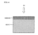
- FIG 4 is a schematic view (cross-sectional view) showing a ceramic filter to which one embodiment of the present invention is applied.
- FIG 5 is a schematic view (cross-sectional view) showing a ceramic filter to which one embodiment of the present invention is applied.
- FIG. 6 is a schematic view (enlarged cross-sectional view) showing a related-art ceramic filter.
- FIG. 7 is a schematic view (cross-sectional view) showing a related-art ceramic filter.
- FIG 8 is a schematic view (perspective view) showing a ceramic filter to which one embodiment of the present invention is applied.
- FIG 9 is a schematic view illustrative of a specimen used for permeability measurement.
- a catalyst-carrying filter 1 includes a honeycomb-structured base material having a plurality of cells 3 that serve as exhaust gas passages and are partitioned by a partition wall 4 formed of a porous ceramic having a number of pores, the partition wall 4 including a gas-inflow-side layer and a gas-outflow-side layer.
- a partition wall 4 formed of a porous ceramic having a number of pores, the partition wall 4 including a gas-inflow-side layer and a gas-outflow-side layer.
- One open end 7a and the other open end 7b of the plurality of cells 3 are alternately plugged by plugging sections.
- the gas-inflow-side layer 13 of the partition wall includes a PM collection layer 9 that has a small average pore size so as to collect particulate matter, and a PM removal catalyst layer 10 that supports or is coated with an oxidizing catalyst for promoting oxidation of particulate matter contained in exhaust gas.
- the gas-outflow-side layer 15 of the partition wall includes a gas purification catalyst layer 11 that supports or is coated with a gas purification catalyst that promotes oxidation of unburned gas.
- the gas-inflow-side layer of the partition wall includes the PM collection layer that has a small average pore size so as to collect particulate matter (PM) that is contained in exhaust gas and mainly contains soot (graphite).
- PM particulate matter
- graphite soot
- gas-inflow-side layer refers to an area (PM collection layer 9) that corresponds to the gas-inflow-side partition wall of the honeycomb-structured base material and is formed to have a small average pore size so as to collect particulate matter.
- gas-inflow-side layer refers to the gas-inflow-side and its vicinity of partition wall 4 (4a), as shown in FIG 3 .
- the gas-inflow-side layer supports or is coated with the PM removal catalyst described later, and serves as the PM removal catalyst layer (see reference numeral 10 shown in FIG 4 ).
- gas-outflow-side layer refers to an area that corresponds to the gas-outflow-side partition wall of the honeycomb-structured base material (see reference numeral 15) and is formed in the gas-outflow-side and its vicinity of partition wall.
- the gas-outflow-side layer corresponds to an area excluding at least the PM collection layer (see symbol 4b).
- gas-outflow-side layer refers to the gas-outflow-side and its vicinity of partition wall shown in FIG. 4 .
- the gas-outflow-side layer supports or is coated with the gas purification catalyst described later, and serves as the gas purification catalyst layer 11.
- the structure of the partition wall of the base material is not limited to the two-layer structure that includes the gas-inflow-side layer and the gas-outflow-side layer.
- a partition wall that includes three or more layers may be formed by providing an intermediate layer that does not support a catalyst between the gas-inflow-side layer and the gas-outflow-side layer.
- FIG. 3 is a schematic view showing the longitudinal cross section of the catalyst-carrying filter according to this embodiment
- FIG 4 is a view schematically showing the cross section of part of the partition wall of the catalyst-carrying filter according to this embodiment.
- the PM removal catalyst layer is formed by causing the PM collection layer to support (be coated with) an oxidizing catalyst (i.e., PM removal catalyst).
- an oxidizing catalyst i.e., PM removal catalyst
- the gas-inflow-side layer of the partition wall of the honeycomb-structured base material according to this embodiment includes roles (functions as) the PM collection layer and a layer that oxidizes PM.
- the gas-outflow-side layer of the partition wall reliably collects and oxidizes PM due to the function of the PM collection layer that is formed in the gas-inflow-side layer (i.e., the surface of the partition wall and the inner wall of the pore formed in the partition wall near the gas inflow side) and collects PM, and the function of oxidizing PM.
- the PM removal catalyst layer and the gas purification catalyst layer can significantly improve the regeneration efficiency of the catalyst-carrying filter in a synergistic manner.
- the oxidizing catalyst is supported on (applied to) the PM collection layer to form the PM removal catalyst layer. Therefore, the oxidizing catalyst (i.e., PM removal catalyst) comes in contact with PM in the PM removal catalyst layer to promote oxidation of PM contained in exhaust gas.
- a noble metal such as platinum (Pt), palladium (Pd), or rhodium (Rh) is suitably used.
- a NOx occlusion catalyst e.g., alkali metal (e.g., Li, Na, K, or Cs) and alkaline earth metal (e.g., Ca, Ba, or Sr)
- a three-way catalyst e.g., a promoter such as cerium (Ce) oxide and/or zirconium (Zr) oxide, a hydrocarbon (HC) adsorbent, and the like may be supported on the PM removal catalyst layer.
- these materials may be may be supported on the gas purification catalyst layer (described later).
- the PM removal catalyst may include Ce and at least one rare earth metal, alkaline earth metal, or transition metal.
- the rare earth metal may be selected from Sm, Gd, Nd, Y, Zr, Ca, La, Pr, and the like.
- the alkaline earth metal included in the PM removal catalyst may be selected from Mg, Ca, Sr, Ba, and the like.
- the transition metal included in the PM removal catalyst may be selected from Mn, Fe, Co, Ni, Cu, Zn, Sc, Ti, V, Cr, and the like.
- the method of causing the PM removal catalyst to support the catalyst component such as the oxidizing catalyst or the NOx occlusion catalyst is not particularly limited.
- the partition wall of the honeycomb structure may be wash-coated with a catalyst solution containing the catalyst component, and heated to a high temperature so that the catalyst component is secured on the partition wall.
- a ceramic slurry may be caused to adhere to the gas-inflow-side layer of the partition wall of the honeycomb-structured base material using a known ceramic film formation method (e.g., dipping), and dried and fired to form a thin PM removal catalyst layer.
- the average pore size of the PM removal catalyst layer may be adjusted to the desired value by controlling the grain size and the mixing ratio of aggregate particles in the ceramic slurry, for example.
- the porosity of the PM removal catalyst layer may be adjusted to the desired value by controlling the grain size of aggregate particles in the ceramic slurry and the amount of pore-forming material, for example.
- the thickness of the coating layer may be adjusted to the desired value by controlling the concentration of the ceramic slurry and the film formation time, for example. Note that two or more coating layers may be formed.
- the catalyst component such as the oxidizing catalyst or the NOx occlusion catalyst be supported on a heat-resistant inorganic oxide having a large specific surface area (e.g., alumina) in advance, and then supported on the partition wall of the honeycomb structure so that the catalyst component is supported in a highly dispersed state.
- a heat-resistant inorganic oxide having a large specific surface area e.g., alumina
- the PM removal catalyst layer may be formed by causing a catalyst slurry to be supported inside the pores formed in the PM collection layer by applying a known catalyst supporting method (e.g., attraction method), and then drying and firing the catalyst slurry, for example.
- a catalyst supporting method e.g., attraction method
- the gas purification catalyst layer according to this embodiment is a layer that includes a gas purification catalyst and is formed by causing the gas-outflow-side and its vicinity of partition wall to support (be coated with) the gas purification catalyst.
- exhaust gas purification catalyst used herein refers to a catalyst component that has a function of purifying exhaust gas, and encompasses any catalyst that promotes purification of a hazardous component (e.g., nitrogen oxide, hydrocarbon, or carbon monoxide) contained in exhaust gas.
- exhaust gas purification catalyst encompasses an oxidizing catalyst that catalyzes oxidation of nitrogen oxide (NOx), a three-way catalyst that catalyzes oxidation of nitrogen oxide and reduction of hydrocarbons and carbon monoxide at the same time, and a NOx occlusion catalyst.
- the gas purification catalyst layer is formed in the gas-outflow-side layer of the partition wall as a layer that promotes oxidation of particulate matter contained in exhaust gas.
- the total amount of catalyst coating used to maintain an equal purification performance during use (hereinafter may be referred to as "total catalyst coating amount") can be reduced by causing the partition wall to support the oxidizing catalyst as the gas purification catalyst. Since ashes are collected by the PM collection layer, a deterioration in the catalyst in the gas purification catalyst layer can be prevented while reducing the total catalyst coating amount.
- a noble metal such as platinum (Pt), palladium (Pd), or rhodium (Rh) is suitably used.
- a NOx occlusion catalyst e.g., alkali metal (e.g., Li, Na, K, or Cs) or alkaline earth metal (e.g., Ca, Ba, or Sr)
- a three-way catalyst e.g., a promoter such as cerium (Ce) oxide and/or zirconium (Zr) oxide, a hydrocarbon (HC) adsorbent, and the like may be supported on the gas purification catalyst layer.
- a NOx occlusion catalyst e.g., alkali metal (e.g., Li, Na, K, or Cs) or alkaline earth metal (e.g., Ca, Ba, or Sr)
- alkali metal e.g., Li, Na, K, or Cs
- alkaline earth metal e.g., Ca, Ba, or Sr
- a promoter such as cerium (Ce) oxide and/or zirconium (Zr) oxide
- HC hydrocarbon
- the method of causing the gas purification catalyst layer to support the catalyst component such as the oxidizing catalyst or the NOx occlusion catalyst is not particularly limited.
- the partition wall of the honeycomb structure may be wash-coated with a catalyst solution containing the catalyst component, and then heated to a high temperature so that the catalyst component is secured on the gas purification catalyst layer.
- the catalyst component such as the oxidizing catalyst or the NOx occlusion catalyst be supported on a heat-resistant inorganic oxide having a large specific surface area (e.g., alumina) in advance, and then supported on the partition wall of the honeycomb structure so that the catalyst component is supported in a highly dispersed state.
- the gas purification catalyst layer is formed in the gas-outflow-side layer of the partition wall as a layer that purifies NOx.
- the gas purification catalyst is supported on the gas-outflow-side and its vicinity of partition wall to form a gas purification catalyst layer.
- the gas purification catalyst layer is formed by causing the NOx purification catalyst to be supported (applied) as the gas purification catalyst, the local O 2 concentration can be reduced by regenerating (oxidizing) PM deposited on the PM collection layer as a gas-inflow-side layer, and the NOx purification efficiency can be increased by the gas purification catalyst layer formed in the gas-outflow-side layer of the partition wall.
- ashes and sulfur do not enter the gas purification catalyst layer that includes the NOx catalyst, a deterioration in the NOx catalyst can be suppressed.
- the NOx purification catalyst may include a metal oxide selected from the group consisting of alumina, zirconia, titanium, and combinations thereof as a coating material.
- NOx purification catalyst examples include NOx occlusion-reduction catalysts and NOx selective reduction catalysts.
- NOx occlusion-reduction catalyst refers to a catalyst that occludes NOx when the air/fuel ratio is in a lean state, and reduces the occluded NOx to N 2 during a rich spike at given intervals (i.e., when exhaust gas is made fuel-rich).
- the NOx occlusion-reduction catalyst may be obtained by causing a metal oxide (e.g., alumina, zirconia, or titania) coating material to support a noble metal (e.g., platinum, palladium, or rhodium) and at least one metal selected from the group consisting of alkali metals and alkaline earth metals.
- NOx selective reduction catalyst refers to a catalyst that causes NOx to selectively react with a reduction component in a lean atmosphere to purify NOx.
- the NOx selective reduction catalyst may be obtained by causing a coating material that contains zeolite or alumina to support at least one metal selected from the group consisting of copper, cobalt, nickel, iron, gallium, lanthanum, cerium, zinc, titanium, calcium, barium, and silver.
- the method of causing the partition wall of the honeycomb structure to support the purification catalyst is not particularly limited.
- the partition wall of the honeycomb structure may be wash-coated with a catalyst solution containing the catalyst component, and then heated at a high temperature so that the catalyst component is secured on the partition wall.
- a ceramic slurry may be caused to adhere to the gas-outflow-side layer of the partition wall of the honeycomb-structured base material using a known ceramic film formation method (e.g., dipping), and then dried and fired to form a thin purification catalyst layer.
- the average pore size of the gas purification catalyst layer may be adjusted to the desired value by controlling the grain size and the mixing ratio of aggregate particles in the ceramic slurry, for example.
- the porosity of the gas purification catalyst layer may be adjusted to the desired value by controlling the grain size of aggregate particles in the ceramic slurry and the amount of pore-forming material, for example.
- the thickness of the coating layer may be adjusted to the desired value by controlling the concentration of the ceramic slurry and the film formation time, for example. Note that two or more coating layers may be formed.
- the catalyst component such as the three-way catalyst, the oxidizing catalyst, or the NOx occlusion catalyst be supported on a heat-resistant inorganic oxide having a large specific surface area (e.g., alumina) in advance, and then supported on the partition wall of the honeycomb structure so that the catalyst component is supported in a highly dispersed state.
- a heat-resistant inorganic oxide having a large specific surface area e.g., alumina
- FIG. 5 is a schematic view (enlarged cross-sectional view) showing the ceramic filter according to the present invention.
- the PM removal catalyst layer and the gas purification catalyst layer according to this embodiment have the following features.
- the PM removal catalyst layer support (be coated with) the oxidizing catalyst in an amount larger than that of the gas purification catalyst layer.
- PM can be reliably removed by the PM removal catalyst layer while suppressing the total amount of catalyst used for the catalyst-carrying filter.
- unburned gas can be reliably oxidized by the gas purification catalyst layer. Specifically, if the amount of oxidizing catalyst is so small that PM is not sufficiently processed by the PM removal catalyst layer, ashes may enter the gas purification catalyst layer. This may cause the catalyst to deteriorate.
- the amount of oxidizing catalyst supported on the PM removal catalyst layer is too large, the pores in the PM collection layer (i.e., gas-inflow-side layer) may be clogged so that a pressure loss due to soot is likely to occur. If the total amount of catalyst supported on the catalyst-carrying filter (PM removal catalyst layer and gas purification catalyst layer) is increased to a large extent, cracks and the like may easily occur during regeneration. Therefore, it is preferable to adjust the total amount of catalyst supported on the catalyst-carrying filter.
- the oxidizing catalyst be supported on the PM removal catalyst layer in an amount larger than that of the gas purification catalyst layer by a factor of 1.05 to 10. If the amount of oxidizing catalyst supported on the PM removal catalyst layer is larger than that of the gas purification catalyst layer by a factor of more than 10, the amount of gas purification catalyst supported on the gas-outflow-side layer is too small. As a result, CO produced due to incomplete combustion during soot regeneration is not sufficiently oxidized in the gas-outflow-side layer (gas purification catalyst layer) so that the CO emission cannot be reduced (CO slippage may occur). Therefore, it is preferable to adjust the amount of oxidizing catalyst within the above desired range.
- the PM removal catalyst layer and the gas purification catalyst layer are made to function sufficiently by adjusting the amount of oxidizing catalyst supported on the PM removal catalyst layer and the gas purification catalyst layer within the above desired range so that the regeneration efficiency can be improved.
- the effects of the present invention can then be achieved due to the characteristics of each catalyst layer.
- the total amount of oxidizing catalyst supported on (applied to) the PM removal catalyst layer and the gas purification catalyst layer be 15 to 180 g/L. If the total amount of oxidizing catalyst is less than 15 g/L, the regeneration efficiency may decrease. Moreover, since the amount of catalyst in the gas-outflow-side layer may become insufficient, the gas emission may not reach 100%. If the total amount of oxidizing catalyst is more than 180 g/L, the pores formed in the gas-inflow-side layer may be clogged by the catalyst so that a pressure loss due to soot may occur. If the amount of pressure loss due to soot increases, the output during acceleration decreases during actual use (impractical).
- the amount of noble metal included in the PM removal catalyst layer be smaller than that of the gas purification catalyst layer. Since a noble metal does not contribute to soot regeneration, the amount of noble metal can be reduced to reduce cost.
- the PM removal catalyst layer does not include a noble metal. Since a noble metal does not contribute to soot regeneration, the amount of noble metal can be reduced to reduce cost.
- the PM removal catalyst layer be formed by causing a ceramic having an aspect ratio of five or more to be coated with the PM removal catalyst.
- the PM removal catalyst can be easily supported or applied. Therefore, the thickness of the surface layer can be easily made uniform, or collected PM and the like can be easily removed.
- the PM collection layer have a small average pore size so as to collect particulate matter.
- the PM collection layer have an average pore size appropriate for collecting particulate matter. Specifically, if the average pore size of the gas-inflow-side layer of the partition wall is too small, the upper part (ash inflow side or its area nearby) of the pores in the PM collection layer may be clogged by ashes when ashes are collected by the PM collection layer. As a result, gas may not reach the gas-outflow-side layer of the partition wall. In this case, oxidation of gas due to the gas purification catalyst supported on the gas-outflow-side layer may be hindered so that the catalyst purification performance decreases.
- an appropriate amount of oxidizing catalyst (PM removal catalyst) be supported on (applied to) the PM removal catalyst layer.
- PM removal catalyst When an appropriate amount of PM removal catalyst is supported on (applied to) the PM removal catalyst layer, PM can be sufficiently collected.
- the gas purification catalyst layer fulfills its function sufficiently.
- the average pore size of the PM removal catalyst layer is smaller than that of the gas purification catalyst layer, even if a defect (pore having a large pore size) is present in the partition wall, a situation in which exhaust gas is concentrated on the defect can be prevented. Moreover, a situation in which particulate matter leaks through the defect toward the gas-outflow-side cells can be prevented.
- the PM collection layer having an average pore size smaller than that of the gas-outflow-side and its vicinity of partition wall is formed on the surface of the gas-inflow-side and its vicinity of partition wall 4 that partitions the plurality of cells of the honeycomb structure, for example.
- the pores and the oxidizing catalyst are omitted.
- the average pore size of the PM collection layer is preferably 1 to 15 ⁇ m. If the average pore size is less than 1 ⁇ m, the permeability decreases so that the permeation resistance of the pores tends to increase rapidly. If the average pore size is more than 15 ⁇ m, the collection performance decreases so that the PM emission may exceed the Euro-5 regulation value. Therefore, the effects of the present invention can be achieved by adjusting the average pore size of the PM collection layer within the above desired range.
- permeability refers to a value calculated by the following expression (1).
- the term “permeability” refers to an index that indicates the passage resistance when a specific gas passes through a sample (partition wall).
- C indicates the permeability (m 2 )
- F indicates the gas flow rate (cm 3 /s)
- T indicates the thickness (cm) of the sample
- V indicates the gas viscosity (dynes ⁇ sec/cm 2 )
- D indicates the diameter (cm) of the sample
- P indicates the gas pressure (PSI).
- 13.839 PSI equals 1 atm
- 68947.6 dynes ⁇ sec/cm 2 equals I PSI.
- C 8 ⁇ FTW ⁇ D 2 ⁇ P 2 - 13.839 2 / 13.839 ⁇ 68947.6 ⁇ 10 - 4
- the permeability is calculated as follows. As shown in FIG 9 , a honeycomb structure or a honeycomb-structured catalyst body is cut into a rectangular or disc-like specimen 103 so that the rib height H is 0.2 mm or less. The passage resistance when causing air at room temperature to pass through the partition wall 4 is measured, and the permeability is calculated by the expression (1). It is desirable to use a fluid seal (e.g., grease) so that air does not leak through an opening between a rib 105 and a seal. The flow rate of air is adjusted so that air passes through the partition wall at a flow rate of 0.1 cm/sec or more and 1 cm/sec or less.
- a fluid seal e.g., grease
- the catalyst coating layer is provided on the cell inner wall and the rib in a different way.
- the permeability of the partition wall of the honeycomb-structured catalyst body can be measured in the same manner as the honeycomb structure.
- average pore size and “porosity” used herein respectively refer to the average pore size and the porosity measured by mercury porosimetry.
- the PM removal catalyst layer have a porosity of 40 to 90%, and more preferably 50 to 80%. If the porosity of the PM removal catalyst layer is less than 40%, a pressure loss may increase. If the porosity of the PM removal catalyst layer is more than 90%, since the strength of the PM removal catalyst layer may become insufficient, the PM removal catalyst layer may be removed from the surface of the partition wall. If the porosity of the PM removal catalyst layer is less than 40%, since a large amount of particulate matter is deposited, filter regeneration becomes difficult. If the porosity of the PM removal catalyst layer is more than 90%, since the strength of the honeycomb structure that forms the catalyst-carrying filter decreases, canning becomes difficult.
- the gas purification catalyst layer have a porosity of 30 to 70%, and more preferably 35 to 60%. If the porosity of the gas purification catalyst layer is less than 30%, a pressure loss may increase. Moreover, PM may not sufficiently come in contact with the oxidizing catalyst in the PM removal catalyst layer formed in the gas inflow area of the cell. If the porosity of the gas purification catalyst layer is more than 70%, since the strength of the gas purification catalyst layer may become insufficient, the PM removal catalyst layer may be removed from the surface of the partition wall.
- the honeycomb-structured base material has a plurality of cells (exhaust gas passages) partitioned by the partition wall 4 formed of a porous ceramic having a number of pores.
- the honeycomb-structured base material is configured as a catalyst-carrying filter in which the partition wall 4 that partitions the cells 3 includes the gas-inflow-side layer 13 and the gas-outflow-side layer 15.
- One open end 7a and the other open end 7b of the cells are alternately plugged by the plugging sections.
- the overall shape of the honeycomb structure is not particularly limited.
- the honeycomb structure may have a cylindrical shape (see FIGS. 1 and 2 ), a quadrangular prism shape, a triangular prism shape, or the like.
- the shape of the cell of the honeycomb-structured base material may be quadrilateral (see FIG 1 ), hexagonal, triangular, or the like.
- the shape of the cell is not limited thereto, but may be an arbitrary known shape.
- the shape of the cell is preferably circular or polygonal having four or more sides. Specifically, since the catalyst is not concentrated on the corner in the cross section of the cell, the thickness of the catalyst layer can be made uniform.
- a hexagonal cell is particularly preferable taking account of the cell density, the aperture ratio, and the like.
- the cell density of the honeycomb-structured base material is not particularly limited.
- the cell density is preferably 6 to 1500 cells/in 2 (0.9 to 233 cells/cm 2 ).
- the thickness of the partition wall is preferably 20 to 2000 ⁇ m.
- the honeycomb-structured base material As the catalyst-carrying filter according to this embodiment, it is preferable that one open end and the other open end of the cells of the honeycomb-structured base material be alternately plugged.
- the honeycomb structure that has a plurality of cells 3 (exhaust gas passages) partitioned by the partition wall 4 formed of a porous ceramic having a number of pores is formed to have a structure in which one open end 7a and the other open end 7b of the cells 3 are alternately plugged by the plugging sections 8, for example.
- the material for the honeycomb-structured base material is not particularly limited.
- a ceramic may be suitably used as the material for the honeycomb-structured base material. It is preferable to use cordierite, silicon carbide, alumina, mullite, or silicon nitride from the viewpoint of strength, heat resistance, corrosion resistance, and the like.
- the honeycomb-structured base material may be produced by mixing and kneading ceramic aggregate particles and water optionally with an organic binder (e.g., hydroxypropoxylmethyl cellulose or methyl cellulose), a pore-forming material (e.g., graphite, starch, or synthetic resin), a surfactant (e.g., ethylene glycol or fatty acid soap), and the like to prepare clay, forming the clay to the desired shape, drying the formed clay to obtain a formed body, and firing the formed body, for example.
- an organic binder e.g., hydroxypropoxylmethyl cellulose or methyl cellulose
- a pore-forming material e.g., graphite, starch, or synthetic resin
- a surfactant e.g., ethylene glycol or fatty acid soap
- the honeycomb structure may be produced as follows. Note that the method of producing the honeycomb structure is not limited thereto.
- the honeycomb structure is a honeycomb segment bonded body 63 that includes a plurality of honeycomb segments 62 (see FIG. 8 ), and is produced by bonding the honeycomb segments 62 through a bonding material 64 and cutting the outer circumferential surface to the desired shape
- the honeycomb structure may be produced as follows.
- the honeycomb segment is produced. Specifically, a SiC powder and a Si metal powder are mixed in a mass ratio of 80:20. After the addition of methyl cellulose, hydroxypropoxylmethyl cellulose, a surfactant, and water, the components are kneaded to obtain plastic clay. The clay is extruded using a specific die to obtain a honeycomb segment formed body having the desired shape. The resulting honeycomb segment formed body is dried using a microwave dryer, completely dried using a hot-blast dryer, plugged, and calcined.
- the honeycomb segment formed body is calcined for degreasing at 550°C for about three hours in an oxidizing atmosphere, for example.
- the calcining conditions are preferably adjusted corresponding to the organic substance (e.g., organic binder, dispersant, and pore-forming material) in the honeycomb formed body.
- the combustion temperature of the organic binder is normally about 100 to 300°C
- the combustion temperature of the pore-forming material is normally about 200 to 800°C. Therefore, the calcining temperature may be set at about 200 to 1000°C.
- the calcining time is normally about 3 to 100 hours.
- the honeycomb segment formed body is then fired.
- firing refers to sintering the forming raw material contained in the calcined body to effect densification so that the resulting body has specific strength.
- the firing conditions (temperature and time) differ depending on the type of forming raw material.
- the firing conditions may be appropriately selected corresponding to the type of forming raw material. For example, when firing the honeycomb segment formed body in an inert atmosphere (argon), the firing temperature is generally set at about 1400 to 1500°C, for example.
- the PM collection layer is then formed on the gas-inflow-side wall (i.e., gas-inflow-side layer).
- the PM collection layer is formed by immersing the honeycomb segment in a slurry that contains a silicon carbide powder, and firing (firing for forming the PM collection layer) the honeycomb segment.
- the average particle diameter of the silicon carbide powder contained in the slurry is preferably 0.3 to 5 ⁇ m.
- the silicon carbide powder is preferably dispersed in a dispersion medium (e.g., organic polymeric material).
- the viscosity of the slurry is preferably adjusted to about 50,000 cp.
- the firing temperature is preferably about 1400 to 1500°C.
- the PM collection layer in the gas-inflow-side layer and the gas-outflow-side layer are formed in this manner. Each layer is coated with a catalyst in a catalyst supporting step described later.
- a plurality of honeycomb segments (sintered bodies) having the desired dimensions are obtained by the above-mentioned steps.
- a bonding slurry prepared by mixing aluminosilicate fibers, colloidal silica, polyvinyl alcohol, and silicon carbide is applied to the periphery of each honeycomb segment.
- the honeycomb segments are then compression-bonded and dried with heating to obtain a honeycomb segment bonded body having a quadrangular prism shape.
- the honeycomb segment bonded body is ground to a cylindrical shape.
- the periphery of the resulting body is coated with a peripheral coating layer formed of the same material as the honeycomb segment formed body.
- the peripheral coating layer is then dried and cured to obtain a cylindrical honeycomb structure having a segmented structure.
- the plugging section is formed as follows. Specifically, a plugging slurry is stored in a storage container. The end face of the honeycomb structure provided with a mask is immersed in the plugging slurry contained in the storage container so that the openings of the cells that are not provided with the mask are filled with the plugging slurry to form plugging sections. The other ends of the cells that are plugged on one end are masked and plugged in the same manner as described above to form plugging sections. As a result, the other ends of the cells are alternately plugged in a checkered pattern. The cells may be plugged after firing the honeycomb formed body to form a honeycomb fired body.
- the same material as the raw material for the honeycomb segment is preferably used as the plugging material.
- the plugging material and the honeycomb segment have the same expansion coefficient during firing, the durability of the honeycomb structure can be increased.
- a dispersion medium e.g., water
- a pore-forming material e.g., an organic binder
- a dispersant e.g., water
- the mixture is kneaded to prepare clay.
- the clay may be prepared by kneading the cordierite-forming raw material (forming raw material) using a kneader, a vacuum kneader, or the like.
- the cordierite raw material is preferably fired at 1410 to 1440°C for about 3 to 10 hours.
- the clay thus prepared may be extruded using a die having the desired cell shape, partition wall thickness, and cell density, for example.
- the catalyst-carrying filter is preferably produced by separately coating the honeycomb structure with the PM removal catalyst and the gas purification catalyst. This facilitates the forming process so that uniform products can be obtained.
- honeycomb structure (that has been bonded and processed) in which the PM collection layer is formed on the gas-inflow-side (gas-inflow-side layer) of the partition wall is provided.
- a slurry of an oxidizing catalyst (PM removal catalyst applied to the gas-inflow-side layer of the partition wall of the honeycomb structure) and a slurry of a gas purification catalyst are prepared.
- the outflow-side cells of the honeycomb structure i.e., the PM collection layer is not applied
- the slurry is absorbed through the inflow-side cells (i.e., the PM collection layer is applied) for a specific time while adjusting the absorption pressure and the absorption flow rate so that the gas purification catalyst is supported on the gas-outflow-side layer.
- honeycomb structure is then dried at 120°C for two hours, and the gas purification catalyst is secured on the honeycomb structure at 550°C for one hour.
- the inflow-side cells of the honeycomb structure are immersed in the slurry of the PM removal catalyst to a specific depth.
- the slurry is absorbed through the outflow-side cells for a specific time while adjusting the absorption pressure and the absorption flow rate so that the PM removal catalyst is supported on the PM collection layer.
- the honeycomb structure is then dried at 120°C for two hours, and the PM removal catalyst is secured on the honeycomb structure at 550°C for one hour.
- a catalyst-carrying filter is thus obtained.
- the honeycomb structure is separately coated with the PM removal catalyst and the gas purification catalyst.
- the method of coating the honeycomb structure with the PM removal catalyst and the gas purification catalyst is not limited thereto.
- a known method may also be used. For example, a dipping method, an absorption method, or the like may be used.
- the catalyst-carrying filter is more preferably produced by coating the honeycomb structure with the PM removal catalyst through the inflow side, and coating the honeycomb structure with the gas purification catalyst through the outflow side.
- the PM removal catalyst can be reliably supported on the gas-inflow-side layer, and the gas purification catalyst can be reliably supported on the gas-outflow-side layer. Therefore, a variation in products can be minimized.
- the second production method is described in detail below.
- the second production method differs from the first production method as to only the method of causing the catalyst to be supported on the honeycomb structure. Therefore, the following description focuses on the method of causing the catalyst to be supported on the honeycomb structure.
- the remaining production steps are omitted as much as possible. Regarding the remaining production steps, refer to the first production method and the method of producing the honeycomb structure described above.
- a honeycomb structure (that has been bonded and processed) in which the PM collection layer is formed in the gas-inflow-side layer of the partition wall is provided in the same manner as in the first production method.
- a slurry of an oxidizing catalyst (PM removal catalyst) and a slurry of a gas purification catalyst are prepared.
- the catalyst composition may be the same as that used in the first production method.
- the outflow side cells of the honeycomb structure (i.e., the PM collection layer is not applied) are immersed in the slurry of the purification catalyst to a specific depth.
- the slurry is absorbed through the inflow-side cells (i.e., the PM collection layer is applied) for a specific time while adjusting the absorption pressure and the absorption flow rate so that the gas purification catalyst is supported on the gas-outflow-side layer.
- the honeycomb structure is then dried at 120°C for two hours.
- the inflow-side cells of the honeycomb structure are then immersed in the slurry of the PM removal catalyst to a specific depth.
- the slurry is absorbed through the outflow-side cells for a specific time while adjusting the absorption pressure and the absorption flow rate so that the PM removal catalyst is supported on the PM collection layer.
- the honeycomb structure is then dried at 120°C for two hours, and the PM removal catalyst is secured on the honeycomb structure at 550°C for one hour. A catalyst-carrying filter is thus obtained.
- the catalyst-carrying filter is most preferably produced by coating the honeycomb structure with the PM removal catalyst and the gas purification catalyst through the inflow side. According to this production method, the forming process can be simplified so that the production speed can be increased. Therefore, the production cost can be reduced.
- the third production method is described in detail below.
- the third production method differs from the first production method as to only the method of causing the catalyst to be supported on the honeycomb structure. Therefore, the following description focuses on the method of causing the catalyst to be supported on the honeycomb structure.
- the remaining production steps are omitted as much as possible. Regarding the remaining production steps, refer to the first production method.
- the relationship between the amount of oxidizing catalyst supported on the gas-outflow-side layer and the amount of catalyst supported on the PM collection layer is controlled only when the PM removal catalyst and the gas purification catalyst are the same oxidizing catalyst, but differ in the amount of oxidizing catalyst supported on the respective layers.
- a honeycomb structure (that has been bonded and processed) in which the PM collection layer is formed in the gas-inflow-side layer of the partition wall is provided in the same manner as in the first production method.
- a slurry of an oxidizing catalyst (PM removal catalyst and gas purification catalyst) is prepared.
- the honeycomb structure is gradually immersed in the slurry from the gas-inflow-side end face, and completely immersed in the slurry.
- the absorption pressure from the gas outflow side is adjusted so that the slurry is uniformly distributed in the pores in the gas-inflow-side layer and the gas-outflow-side layer.
- the honeycomb structure is then dried at 120°C for two hours, and the catalyst is secured on the honeycomb structure at 550°C for one hour. A catalyst-carrying filter is thus obtained.
- a catalyst-carrying filter was produced using a honeycomb structure described below.
- a honeycomb structure (i.e., base material of catalyst-carrying filter) was produced as follows. A mixed powder of 80 mass% of a SiC powder and 20 mass% of a Si metal powder was used as the raw material. Methyl cellulose, hydroxypropoxylmethyl cellulose, a surfactant, and water were added to the mixed powder to prepare plastic clay. The clay was extruded using an extruder to obtain sixteen (4 ⁇ 4) honeycomb segments having the desired dimensions. The honeycomb segments were dried using microwaves and a hot blast, plugged on either end of the cells in a checkered pattern, and calcined (for degreasing) at 550°C for three hours in an oxidizing atmosphere.
- honeycomb segments were fired at 1700°C for two hours in an inert atmosphere (argon) to obtain a plurality of honeycomb segments (sintered bodies) in which SiC crystal particles are bonded through Si.
- a bonding slurry was applied to the periphery of each honeycomb segment (sintered body).
- the honeycomb segments were compression-bonded and dried with heating to obtain a honeycomb segment bonded body in the shape of a quadrangular prism.
- the honeycomb segment bonded body was ground to a cylindrical shape.
- the periphery of the resulting body was coated with a peripheral coating layer formed of the same material as the honeycomb segment formed body.
- the peripheral coating layer was dried and cured to obtain a honeycomb structure (144 ⁇ 152 mm, 12 mil/300 cpsi).
- the thickness of the gas-inflow-side partition wall as a PM collection layer was 50 ⁇ m.
- a collection layer having a thickness of 50 ⁇ m was formed on the gas-outflow-side layer having the wall thickness of 305 ⁇ m.
- the honeycomb structure was then dried at 120°C for two hours, and the catalyst was secured on the honeycomb structure at 550°C for one hour to produce a honeycomb-structured silicon carbide sintered body (SiC-DPF).
- An oxidizing catalyst was used.
- the partition wall of the above-mentioned SiC-DPF was wash-coated with a catalyst solution containing an oxidizing catalyst component at the desired location and amount corresponding to the examples and comparative examples, and heated at a high temperature to obtain a catalyst-carrying filter.
- a catalyst B (B-1 to B-5) and a catalyst C (C-1 to C-5) were prepared so that the ceria amount ratio differed from that of the catalyst A (the total catalytic amount was identical with that of the catalyst A) (see Table 1).
- a catalyst D (D-1 to B-3) and a catalyst E (E-1 to E-3) were prepared so that the platinum ratio differed from that of the catalyst A (the total catalytic amount was identical with that of the catalyst A) (see Table 1).
- the details are shown in Examples 1 to 14 and Comparative Examples I to 10.
- the catalyst was supported on the gas purification layer by absorbing the catalyst slurry from the outflow-side end face.
- the catalyst was supported on the PM collection layer by absorbing the catalyst slurry from the inflow-side end face.
- the honeycomb structure was then dried at 120°C for two hours, and the catalyst was secured on the honeycomb structure at 550°C for one hour.
- Catalyst-carrying filters of Examples 1 to 6 were obtained in the same manner as described above, except for setting the pore size of the PM collection layer at 5 ⁇ m, setting the porosity of the PM collection layer at 70%, setting the pore size of the gas-outflow-side layer at 15 ⁇ m, setting the porosity of the gas-outflow-side layer at 40%, causing the catalyst A to be supported (applied) as the PM removal catalyst, and causing the catalyst A to be supported (applied) as the gas purification catalyst.
- the catalyst amount ratio, the total catalyst amount, and the like are shown in Table 1.
- a catalyst-carrying filter of Example was obtained in the same manner as described above, except for setting the pore size of the PM collection layer at 1 ⁇ m, setting the porosity of the PM collection layer at 70%, setting the pore size of the gas-outflow-side layer at 15 ⁇ m, setting the porosity of the gas-outflow-side layer at 40%, causing the catalyst A to be supported (applied) as the PM removal catalyst, and causing the catalyst A to be supported (applied) as the gas purification catalyst.
- the catalyst amount ratio, the total catalyst amount, and the like are shown in Table 1.
- a catalyst-carrying filter of Example 8 was obtained in the same manner as described above, except for setting the pore size of the PM collection layer at 15 ⁇ m, setting the porosity of the PM collection layer at 70%, setting the pore size of the gas-outflow-side layer at 15 ⁇ m, setting the porosity of the gas-outflow-side layer at 40%, causing the catalyst A to be supported (applied) as the PM removal catalyst, and causing the catalyst A to be supported (applied) as the gas purification catalyst.
- the catalyst amount ratio, the total catalyst amount, and the like are shown in Table 1.
- a catalyst-carrying filter of Example 9 was obtained in the same manner as described above, except for setting the pore size of the PM collection layer at 3 ⁇ m, setting the porosity of the PM collection layer at 90%, setting the pore size of the gas-outflow-side layer at 15 ⁇ m, setting the porosity of the gas-outflow-side layer at 40%, causing the catalyst A to be supported (applied) as the PM removal catalyst, and causing the catalyst A to be supported (applied) as the gas purification catalyst.
- the catalyst amount ratio, the total catalyst amount, and the like are shown in Table 1.
- a catalyst-carrying filter of Example 10 was obtained in the same manner as described above, except for setting the pore size of the PM collection layer at 5 ⁇ m, setting the porosity of the PM collection layer at 70%, setting the pore size of the gas-outflow-side layer at 15 ⁇ m, setting the porosity of the gas-outflow-side layer at 40%, causing the catalyst B-2 to be supported (applied) as the PM removal catalyst, and causing the catalyst C-2 to be supported (applied) as the gas purification catalyst.
- a catalyst-carrying filter of Example 11 was obtained in the same manner as the catalyst-carrying filter of Example 10, except for causing the catalyst B-3 to be supported (applied) as the PM removal catalyst, and causing the catalyst C-3 to be supported (applied) as the gas purification catalyst.
- a catalyst-carrying filter of Example 12 was obtained in the same manner as the catalyst-carrying filter of Example 10, except for causing the catalyst B-4 to be supported (applied) as the PM removal catalyst, and causing the catalyst C-4 to be supported (applied) as the gas purification catalyst.
- the catalyst amount ratio, the total catalyst amount, and the like are shown in Table 1.
- a catalyst-carrying filter of Example 13 was obtained in the same manner as described above, except for setting the pore size of the PM collection layer at 5 ⁇ m, setting the porosity of the PM collection layer at 70%, setting the pore size of the gas-outflow-side layer at 15 ⁇ m, setting the porosity of the gas-outflow-side layer at 40%, causing the catalyst D-1 to be supported (applied) as the PM removal catalyst, and causing the catalyst E-1 to be supported (applied) as the gas purification catalyst.
- a catalyst-carrying filter of Example 14 was obtained in the same manner as the catalyst-carrying filter of Example 13, except for causing the catalyst D-2 to be supported (applied) as the PM removal catalyst, and causing the catalyst E-2 to be supported (applied) as the gas purification catalyst.
- the catalyst amount ratio, the total catalyst amount, and the like are shown in Table 1.
- Catalyst-carrying filters of Comparative Examples 1 to 5 were obtained in the same manner as described above, except for setting the pore size of the PM collection layer at 5 ⁇ m, setting the porosity of the PM collection layer at 70% and that of gas-outflow-side layer at 40% respectively, causing the catalyst A to be supported (applied) as the PM removal catalyst, and causing the catalyst A to be supported (applied) as the gas purification catalyst.
- the catalyst amount ratio, the total catalyst amount, and the like are shown in Table 1.
- a catalyst-carrying filter of Comparative Example 6 was obtained in the same manner as described above, except for setting the pore size of the PM collection layer at 0.5 ⁇ m, setting the porosity of the PM collection layer at 70%, causing the catalyst A to be supported (applied) as the PM removal catalyst, and causing the catalyst A to be supported (applied) as the gas purification catalyst.
- a catalyst-carrying filter of Comparative Example 7 was obtained in the same manner as the catalyst-carrying filter of Comparative Example 6, except for setting the pore size of the PM collection layer at 17 ⁇ m, setting the porosity of the PM collection layer at 70%, causing the catalyst A to be supported (applied) as the PM removal catalyst, and causing the catalyst A to be supported (applied) as the gas purification catalyst.
- the catalyst amount ratio, the total catalyst amount, and the like are shown in Table 1.
- a catalyst-carrying filter of Comparative Example 8 was obtained in the same manner as described above, except for setting the pore size of the PM collection layer at 17 ⁇ m, setting the porosity of the PM collection layer at 70%, setting the pore size of the gas-outflow-side layer at 15 ⁇ m, setting the porosity of the gas-outflow-side layer at 40%, causing the catalyst B-1 to be supported (applied) as the PM removal catalyst, and causing the catalyst C-1 to be supported (applied) as the gas purification catalyst.
- a catalyst-carrying filter of Comparative Example 9 was obtained in the same manner as the catalyst-carrying filter of Comparative Example 8, except for causing the catalyst B-5 to be supported (applied) as the PM removal catalyst, and causing the catalyst C-5 to be supported (applied) as the gas purification catalyst, and a catalyst-carrying filter of Comparative Example 10 was obtained in the same manner as the catalyst-carrying filter of Comparative Example 8, except for causing the catalyst D-3 to be supported (applied) as the PM removal catalyst, and causing the catalyst E-3 to be supported (applied) as the gas purification catalyst.
- the catalyst amount ratio, the total catalyst amount, and the like are shown in Table 1.
- the catalyst-coated DPF was connected to a diesel engine (2.0 liter). 8 g/L of PM was deposited on the DPF at 2000 rpm ⁇ 50 Nm. The exhaust gas temperature was increased by post injection, and the DPF inlet gas temperature was controlled at 650°C for 10 minutes. After stopping post injection, the DPF was removed. The amount of PM deposited on the DPF was then measured, and the regeneration efficiency (PM combustion efficiency) was calculated from the weight measured before and after the test.
- the DPF was installed in a vehicle equipped with a diesel engine (2.0 liter), and an emission test was conducted in accordance with the European regulation mode. The PM emission was measured to evaluate the collection performance of the DPF.
- the catalyst distributions of the catalyst-coated DPFs of the examples and comparative examples were observed using a scanning electron microscope (SEM).
- SEM scanning electron microscope
- the chemical components were quantitatively analyzed by energy dispersive X-ray spectroscopy (EDX).
- EDX energy dispersive X-ray spectroscopy
- the integrated value of the catalyst components at each measurement position was taken as the amount of catalyst supported at each measurement position. Specifically, the catalyst distribution was observed at an SEM magnification of 1000.
- the chemical components were observed by EDX.
- the chemical components were then analyzed by EDX.
- the catalyst components were then quantitatively analyzed by EDX.
- the specimens were sampled from the catalyst-coated DPFs of Examples I to 4 and Comparative Examples 1 and 2 (1-1) at about 30 mm each from the inlet and the outlet in the DPF axial direction on upstream side and downstream side respectively as well as at the center in the axial direction corresponding to middle stream portion.
- the specimens were sampled at the center in the cross section on upstream and downstream side as well as on middle stream.
- the amount of catalyst on gas-inflow-side was measured at the center in the direction of the thickness of the gas-inflow-side layer and the amount of catalyst on gas-outflow-side was measured upstream in the direction of the thickness thereof; at about 50 ⁇ m from the interface between the PM collection layer and gas-outflow-side layer as well as the amount of catalyst on middle stream part was measured about 50 ⁇ m from the interface of the gas-outflow-side layer.
- the average value of the values measured at three locations was taken as the amount of catalyst in each layer.
- the soot combustion rate was increased by increasing the amount of catalyst in the PM collection layer in order to promote combustion of soot so that the regeneration efficiency was improved.
- the DPF of Comparative Example 1 having a small catalyst amount ratio had a regeneration efficiency of 50 % or less. Therefore, since the DPF of Comparative Example 1 must be regenerated at reduced intervals when the DPF of Comparative Example 1 is subjected to repeated regeneration, the DPF must be regenerated at a high frequency during actual use. This means that the fuel consumption significantly increases (i.e., impractical).
- catalyst amount ratio refers to the catalyst density ratio (hereinafter the same).
- the DPF of Example 9 in which glass fibers having a diameter of 2 to 5 ⁇ m and a length of 20 to 100 s ⁇ m were used for the collection layer, showed an improved collection performance and a reduced PM emission.
- the regeneration efficiency decreased to less than 40% when the ceria amount ratio was less than 1.2 (Comparative Example 8).
- the ceria amount ratio was more than 10 (Comparative Example 9)
- the amount of oxygen occlusion catalyst in the gas-outflow-side layer decreased to a large extent, the amount of oxygen became locally insufficient during CO oxidation.
- the HC gas emission did not reach 100%.
- the DPFs of Comparative Examples 8 and 9 are impractical.
- the regeneration efficiency was more than 450% when the ceria amount ratio was 1.2 or more (Examples 10 to 12) in the same manner as in the case of increasing the catalyst amount ratio.
- the catalyst-carrying filter according to the present invention may be suitably used to collect or purify particulate matter contained in exhaust gas discharged from an internal combustion engine (e.g., diesel engine, ordinary vehicle engine, and large-size vehicle (e.g., truck and bus) engine) or a combustion apparatus.
- an internal combustion engine e.g., diesel engine, ordinary vehicle engine, and large-size vehicle (e.g., truck and bus) engine
- a combustion apparatus e.g., diesel engine, ordinary vehicle engine, and large-size vehicle (e.g., truck and bus) engine
Landscapes
- Chemical & Material Sciences (AREA)
- Engineering & Computer Science (AREA)
- Chemical Kinetics & Catalysis (AREA)
- Combustion & Propulsion (AREA)
- Materials Engineering (AREA)
- Organic Chemistry (AREA)
- Mechanical Engineering (AREA)
- General Engineering & Computer Science (AREA)
- Biomedical Technology (AREA)
- Environmental & Geological Engineering (AREA)
- Analytical Chemistry (AREA)
- General Chemical & Material Sciences (AREA)
- Oil, Petroleum & Natural Gas (AREA)
- Health & Medical Sciences (AREA)
- Catalysts (AREA)
- Processes For Solid Components From Exhaust (AREA)
- Exhaust Gas Treatment By Means Of Catalyst (AREA)
- Filtering Materials (AREA)
- Filtering Of Dispersed Particles In Gases (AREA)
Applications Claiming Priority (1)
| Application Number | Priority Date | Filing Date | Title |
|---|---|---|---|
| JP2008067654A JP5419371B2 (ja) | 2008-03-17 | 2008-03-17 | 触媒担持フィルタ |
Publications (2)
| Publication Number | Publication Date |
|---|---|
| EP2103342A1 true EP2103342A1 (fr) | 2009-09-23 |
| EP2103342B1 EP2103342B1 (fr) | 2016-12-28 |
Family
ID=40786699
Family Applications (1)
| Application Number | Title | Priority Date | Filing Date |
|---|---|---|---|
| EP09250719.3A Active EP2103342B1 (fr) | 2008-03-17 | 2009-03-13 | Filtre revêtu avec un catalyseur |
Country Status (3)
| Country | Link |
|---|---|
| US (1) | US8894943B2 (fr) |
| EP (1) | EP2103342B1 (fr) |
| JP (1) | JP5419371B2 (fr) |
Cited By (4)
| Publication number | Priority date | Publication date | Assignee | Title |
|---|---|---|---|---|
| WO2015060015A1 (fr) * | 2013-10-22 | 2015-04-30 | Toyota Jidosha Kabushiki Kaisha | Dispositif de purification d'échappement pour moteur à combustion interne |
| WO2015072242A1 (fr) * | 2013-11-18 | 2015-05-21 | Toyota Jidosha Kabushiki Kaisha | Système d'épuration des gaz d'échappement pour moteur à combustion interne |
| EP2927444A4 (fr) * | 2012-11-28 | 2016-08-24 | Toyota Motor Co Ltd | Filtre d'épuration d'échappement |
| WO2017209083A1 (fr) * | 2016-06-02 | 2017-12-07 | Cataler Corporation | Filtre de purification de gaz d'échappement |
Families Citing this family (17)
| Publication number | Priority date | Publication date | Assignee | Title |
|---|---|---|---|---|
| KR101621983B1 (ko) | 2008-02-05 | 2016-05-31 | 바스프 코포레이션 | 미립자 트랩을 갖는 가솔린 엔진 배출물 처리 시스템 |
| DE102009018422A1 (de) * | 2009-04-22 | 2010-11-04 | Emitec Gesellschaft Für Emissionstechnologie Mbh | Verfahren zur Herstellung eines beschichteten Wabenkörpers |
| JP5726414B2 (ja) * | 2009-11-18 | 2015-06-03 | 日本碍子株式会社 | 触媒担持フィルタ、及び排ガス浄化システム |
| DE102010006289A1 (de) | 2010-01-30 | 2011-08-04 | Daimler AG, 70327 | Partikelfilter für eine Abgasanlage eines Kraftwagens |
| JP5498821B2 (ja) * | 2010-03-12 | 2014-05-21 | 日本碍子株式会社 | ハニカムフィルタ及びその製造方法 |
| EP2556871B1 (fr) | 2010-03-31 | 2016-09-07 | NGK Insulators, Ltd. | Filtre en nid d'abeilles |
| WO2011125767A1 (fr) * | 2010-03-31 | 2011-10-13 | 日本碍子株式会社 | Filtre en nid d'abeilles |
| US8815189B2 (en) | 2010-04-19 | 2014-08-26 | Basf Corporation | Gasoline engine emissions treatment systems having particulate filters |
| KR101200078B1 (ko) * | 2011-04-15 | 2012-11-12 | 주식회사 아모그린텍 | 단위 촉매 담체 블록과 이를 이용한 대용량 촉매 담체 및 촉매 컨버터 |
| WO2013145316A1 (fr) * | 2012-03-30 | 2013-10-03 | イビデン株式会社 | Filtre en nid d'abeilles et procédé de production d'un filtre en nid d'abeilles |
| JP6074306B2 (ja) * | 2013-03-29 | 2017-02-01 | 日本碍子株式会社 | ハニカム構造体 |
| CN107349684A (zh) * | 2017-08-23 | 2017-11-17 | 北京大督硅藻新材料技术股份有限公司 | 一种复合无纺布及其制备方法和应用 |
| JP7049156B2 (ja) * | 2018-03-30 | 2022-04-06 | 日本碍子株式会社 | ハニカムフィルタ |
| JP7211893B2 (ja) * | 2019-05-24 | 2023-01-24 | トヨタ自動車株式会社 | 排ガス浄化装置 |
| JP7386626B2 (ja) | 2019-06-18 | 2023-11-27 | 株式会社キャタラー | パティキュレートフィルタ |
| JP7414413B2 (ja) | 2019-06-26 | 2024-01-16 | 株式会社キャタラー | パティキュレートフィルタ |
| JP7381372B2 (ja) | 2020-03-12 | 2023-11-15 | トヨタ自動車株式会社 | 排ガス浄化装置 |
Citations (10)
| Publication number | Priority date | Publication date | Assignee | Title |
|---|---|---|---|---|
| US5114581A (en) * | 1991-01-10 | 1992-05-19 | Ceramem Corporation | Back-flushable filtration device and method of forming and using same |
| JPH07106290B2 (ja) | 1984-04-23 | 1995-11-15 | エンゲルハード・コーポレーシヨン | ジーゼル排気粒子用フイルター |
| WO1999047238A1 (fr) * | 1998-03-19 | 1999-09-23 | Ceramem Corporation | Filtres passifs a regeneration catalytique et systeme et procedes associes d'elimination de la suie de sources de combustion |
| JP2003053121A (ja) | 2001-08-10 | 2003-02-25 | Amano Corp | セラミックスフィルタの製造法 |
| US20040191133A1 (en) * | 2003-03-28 | 2004-09-30 | Ngk Insulators, Ltd. | Catalyst-carried filter, exhaust gas purification system using the same, and catalyst body |
| EP1512850A1 (fr) * | 2003-09-04 | 2005-03-09 | J. Eberspächer GmbH & Co. KG | Filtre à particules |
| WO2005084806A1 (fr) * | 2004-03-05 | 2005-09-15 | Johnson Matthey Public Limited Company | Procede de fabrication d'un filtre traversant a parois en ceramique |
| DE102004040548A1 (de) * | 2004-08-21 | 2006-02-23 | Umicore Ag & Co. Kg | Verfahren zum Beschichten eines Wandflußfilters mit feinteiligen Feststoffen und damit erhaltenes Partikelfilter und seine Verwendung |
| EP2067518A2 (fr) * | 2007-12-06 | 2009-06-10 | Honda Motor Co., Ltd. | Appareil de catalyseur d'oxydation pour la purification des gaz d'échappement |
| EP2072129A2 (fr) * | 2007-12-06 | 2009-06-24 | Honda Motor Co., Ltd. | Procédé de production d'appareil de catalyseur d'oxydation pour purifier des gaz d'échappement |
Family Cites Families (18)
| Publication number | Priority date | Publication date | Assignee | Title |
|---|---|---|---|---|
| US5100632A (en) * | 1984-04-23 | 1992-03-31 | Engelhard Corporation | Catalyzed diesel exhaust particulate filter |
| US5286699A (en) * | 1988-12-09 | 1994-02-15 | Nippon Shokubai Kagaku Kogyo Co., Ltd. | Exhaust gas purifying catalyst suppressing the generation of hydrogen sulfide and method of making the catalyst |
| US5221484A (en) * | 1991-01-10 | 1993-06-22 | Ceramem Separations Limited Partnership | Catalytic filtration device and method |
| JPH07106290A (ja) | 1993-09-30 | 1995-04-21 | Matsushita Electric Ind Co Ltd | 電子部品用異物除去装置 |
| JP3698906B2 (ja) * | 1999-01-13 | 2005-09-21 | 日本碍子株式会社 | 複層構造ハニカムフィルタ及びその製造方法 |
| JP3435103B2 (ja) * | 1999-09-14 | 2003-08-11 | 日本碍子株式会社 | 集塵用ハニカムフィルタ及びその製造方法 |
| JP3613669B2 (ja) * | 2000-01-19 | 2005-01-26 | トヨタ自動車株式会社 | 内燃機関の排気浄化装置 |
| JP3843746B2 (ja) * | 2001-03-15 | 2006-11-08 | いすゞ自動車株式会社 | 連続再生型ディーゼルパティキュレートフィルタシステムとその再生制御方法 |
| JP2002309921A (ja) | 2001-04-16 | 2002-10-23 | Denso Corp | 排気浄化装置及びその製造方法 |
| JP2003097250A (ja) * | 2001-09-20 | 2003-04-03 | Mitsubishi Motors Corp | 排気浄化装置 |
| JP3879522B2 (ja) * | 2002-01-28 | 2007-02-14 | トヨタ自動車株式会社 | 内燃機関の排気浄化装置、および、該排気浄化装置のパティキュレートフィルタに触媒を担持させる触媒担持方法 |
| DE10335785A1 (de) | 2003-08-05 | 2005-03-10 | Umicore Ag & Co Kg | Katalysatoranordnung und Verfahren zur Reinigung des Abgases von mager betriebenen Verbrennungsmotoren |
| US7722829B2 (en) * | 2004-09-14 | 2010-05-25 | Basf Catalysts Llc | Pressure-balanced, catalyzed soot filter |
| JP2006326573A (ja) * | 2005-04-27 | 2006-12-07 | Mazda Motor Corp | ディーゼルパティキュレートフィルタ |
| JP4687330B2 (ja) * | 2005-08-23 | 2011-05-25 | マツダ株式会社 | ディーゼルパティキュレートフィルタ |
| JP2007117954A (ja) * | 2005-10-31 | 2007-05-17 | Toyota Motor Corp | ディーゼル排ガス浄化用触媒 |
| JP2007296512A (ja) * | 2006-04-05 | 2007-11-15 | Ngk Insulators Ltd | ハニカムフィルタ |
| JP5291966B2 (ja) * | 2008-03-25 | 2013-09-18 | 日本碍子株式会社 | 触媒担持フィルタ |
-
2008
- 2008-03-17 JP JP2008067654A patent/JP5419371B2/ja active Active
-
2009
- 2009-03-05 US US12/398,637 patent/US8894943B2/en active Active
- 2009-03-13 EP EP09250719.3A patent/EP2103342B1/fr active Active
Patent Citations (11)
| Publication number | Priority date | Publication date | Assignee | Title |
|---|---|---|---|---|
| JPH07106290B2 (ja) | 1984-04-23 | 1995-11-15 | エンゲルハード・コーポレーシヨン | ジーゼル排気粒子用フイルター |
| US5114581A (en) * | 1991-01-10 | 1992-05-19 | Ceramem Corporation | Back-flushable filtration device and method of forming and using same |
| JP2607898Y2 (ja) | 1991-01-10 | 2007-01-24 | セラメム コーポレーション | 逆フラッシュ可能なろ過装置 |
| WO1999047238A1 (fr) * | 1998-03-19 | 1999-09-23 | Ceramem Corporation | Filtres passifs a regeneration catalytique et systeme et procedes associes d'elimination de la suie de sources de combustion |
| JP2003053121A (ja) | 2001-08-10 | 2003-02-25 | Amano Corp | セラミックスフィルタの製造法 |
| US20040191133A1 (en) * | 2003-03-28 | 2004-09-30 | Ngk Insulators, Ltd. | Catalyst-carried filter, exhaust gas purification system using the same, and catalyst body |
| EP1512850A1 (fr) * | 2003-09-04 | 2005-03-09 | J. Eberspächer GmbH & Co. KG | Filtre à particules |
| WO2005084806A1 (fr) * | 2004-03-05 | 2005-09-15 | Johnson Matthey Public Limited Company | Procede de fabrication d'un filtre traversant a parois en ceramique |
| DE102004040548A1 (de) * | 2004-08-21 | 2006-02-23 | Umicore Ag & Co. Kg | Verfahren zum Beschichten eines Wandflußfilters mit feinteiligen Feststoffen und damit erhaltenes Partikelfilter und seine Verwendung |
| EP2067518A2 (fr) * | 2007-12-06 | 2009-06-10 | Honda Motor Co., Ltd. | Appareil de catalyseur d'oxydation pour la purification des gaz d'échappement |
| EP2072129A2 (fr) * | 2007-12-06 | 2009-06-24 | Honda Motor Co., Ltd. | Procédé de production d'appareil de catalyseur d'oxydation pour purifier des gaz d'échappement |
Cited By (9)
| Publication number | Priority date | Publication date | Assignee | Title |
|---|---|---|---|---|
| EP2927444A4 (fr) * | 2012-11-28 | 2016-08-24 | Toyota Motor Co Ltd | Filtre d'épuration d'échappement |
| WO2015060015A1 (fr) * | 2013-10-22 | 2015-04-30 | Toyota Jidosha Kabushiki Kaisha | Dispositif de purification d'échappement pour moteur à combustion interne |
| US9879585B2 (en) | 2013-10-22 | 2018-01-30 | Toyota Jidosha Kabushiki Kaisha | Exhaust purification device for internal combustion engine |
| WO2015072242A1 (fr) * | 2013-11-18 | 2015-05-21 | Toyota Jidosha Kabushiki Kaisha | Système d'épuration des gaz d'échappement pour moteur à combustion interne |
| US9790828B2 (en) | 2013-11-18 | 2017-10-17 | Toyota Jidosha Kabushiki Kaisha | Exhaust purification system for internal combustion engine |
| WO2017209083A1 (fr) * | 2016-06-02 | 2017-12-07 | Cataler Corporation | Filtre de purification de gaz d'échappement |
| CN109219478A (zh) * | 2016-06-02 | 2019-01-15 | 株式会社科特拉 | 废气净化过滤器 |
| US10807032B2 (en) | 2016-06-02 | 2020-10-20 | Cataler Corporation | Exhaust gas purification filter |
| CN109219478B (zh) * | 2016-06-02 | 2021-09-10 | 株式会社科特拉 | 废气净化过滤器 |
Also Published As
| Publication number | Publication date |
|---|---|
| JP5419371B2 (ja) | 2014-02-19 |
| US8894943B2 (en) | 2014-11-25 |
| EP2103342B1 (fr) | 2016-12-28 |
| US20090229259A1 (en) | 2009-09-17 |
| JP2009220029A (ja) | 2009-10-01 |
Similar Documents
| Publication | Publication Date | Title |
|---|---|---|
| US8894943B2 (en) | Catalyst-carrying filter | |
| EP2105200B1 (fr) | Filtre revêtu avec un catalyseur | |
| JP5726414B2 (ja) | 触媒担持フィルタ、及び排ガス浄化システム | |
| EP2105199B1 (fr) | Filtre revêtu avec un catalyseur | |
| EP2174701B1 (fr) | Filtre en nids d'abeilles | |
| JP5208886B2 (ja) | 触媒担持フィルタ | |
| JP6023395B2 (ja) | 触媒担持フィルタ | |
| JP5390438B2 (ja) | ハニカム触媒体 | |
| EP2339135B1 (fr) | Substrat avec couche de collecte en surface et substrat revêtit de catalyseur avec couche de collecte en surface | |
| JP5548470B2 (ja) | ハニカム触媒体 | |
| JP5775512B2 (ja) | ハニカムフィルタ及びハニカムフィルタの製造方法 | |
| JPWO2006041174A1 (ja) | セラミックハニカム構造体 | |
| JP5379039B2 (ja) | 排ガス浄化装置及び排ガス浄化方法 | |
| EP2380649A1 (fr) | Dispositif de purification des gaz d'échappement | |
| WO2008044269A1 (fr) | Structure en nid d'abeilles | |
| JP2008296141A (ja) | ハニカムフィルタ | |
| EP2108448B1 (fr) | Corps de catalyseur en nid d'abeille | |
| EP2108494B1 (fr) | Procédé de fabrication de structure en nid d'abeille | |
| JP2008168279A (ja) | ハニカム構造体 | |
| CN113661311A (zh) | 排气净化过滤器 | |
| US20200386134A1 (en) | Filter and method for manufacturing same | |
| JP2012184658A (ja) | 排ガス浄化装置 | |
| KR101933917B1 (ko) | Dpf의 채널 내부 표면 상 촉매 코팅방법 |
Legal Events
| Date | Code | Title | Description |
|---|---|---|---|
| PUAI | Public reference made under article 153(3) epc to a published international application that has entered the european phase |
Free format text: ORIGINAL CODE: 0009012 |
|
| AK | Designated contracting states |
Kind code of ref document: A1 Designated state(s): AT BE BG CH CY CZ DE DK EE ES FI FR GB GR HR HU IE IS IT LI LT LU LV MC MK MT NL NO PL PT RO SE SI SK TR |
|
| AX | Request for extension of the european patent |
Extension state: AL BA RS |
|
| 17P | Request for examination filed |
Effective date: 20100310 |
|
| AKX | Designation fees paid |
Designated state(s): DE FR |
|
| 17Q | First examination report despatched |
Effective date: 20110301 |
|
| GRAP | Despatch of communication of intention to grant a patent |
Free format text: ORIGINAL CODE: EPIDOSNIGR1 |
|
| INTG | Intention to grant announced |
Effective date: 20160722 |
|
| RIN1 | Information on inventor provided before grant (corrected) |
Inventor name: MIZUTANI, TAKASHI |
|
| GRAS | Grant fee paid |
Free format text: ORIGINAL CODE: EPIDOSNIGR3 |
|
| GRAA | (expected) grant |
Free format text: ORIGINAL CODE: 0009210 |
|
| RAP1 | Party data changed (applicant data changed or rights of an application transferred) |
Owner name: NGK INSULATORS, LTD. |
|
| AK | Designated contracting states |
Kind code of ref document: B1 Designated state(s): DE FR |
|
| REG | Reference to a national code |
Ref country code: DE Ref legal event code: R096 Ref document number: 602009043343 Country of ref document: DE |
|
| REG | Reference to a national code |
Ref country code: DE Ref legal event code: R097 Ref document number: 602009043343 Country of ref document: DE |
|
| PLBE | No opposition filed within time limit |
Free format text: ORIGINAL CODE: 0009261 |
|
| STAA | Information on the status of an ep patent application or granted ep patent |
Free format text: STATUS: NO OPPOSITION FILED WITHIN TIME LIMIT |
|
| 26N | No opposition filed |
Effective date: 20170929 |
|
| REG | Reference to a national code |
Ref country code: FR Ref legal event code: ST Effective date: 20171130 |
|
| PG25 | Lapsed in a contracting state [announced via postgrant information from national office to epo] |
Ref country code: FR Free format text: LAPSE BECAUSE OF NON-PAYMENT OF DUE FEES Effective date: 20170331 |
|
| PGFP | Annual fee paid to national office [announced via postgrant information from national office to epo] |
Ref country code: DE Payment date: 20240130 Year of fee payment: 16 |