WO2013145316A1 - Filtre en nid d'abeilles et procédé de production d'un filtre en nid d'abeilles - Google Patents
Filtre en nid d'abeilles et procédé de production d'un filtre en nid d'abeilles Download PDFInfo
- Publication number
- WO2013145316A1 WO2013145316A1 PCT/JP2012/058744 JP2012058744W WO2013145316A1 WO 2013145316 A1 WO2013145316 A1 WO 2013145316A1 JP 2012058744 W JP2012058744 W JP 2012058744W WO 2013145316 A1 WO2013145316 A1 WO 2013145316A1
- Authority
- WO
- WIPO (PCT)
- Prior art keywords
- honeycomb filter
- cell
- honeycomb
- cell wall
- filter according
- Prior art date
Links
- 238000004519 manufacturing process Methods 0.000 title claims description 43
- 210000004027 cell Anatomy 0.000 claims abstract description 189
- 210000002421 cell wall Anatomy 0.000 claims abstract description 158
- 239000002245 particle Substances 0.000 claims abstract description 158
- 239000003054 catalyst Substances 0.000 claims abstract description 157
- 239000000919 ceramic Substances 0.000 claims abstract description 128
- 239000012530 fluid Substances 0.000 claims abstract description 118
- 239000011148 porous material Substances 0.000 claims abstract description 64
- 238000001914 filtration Methods 0.000 claims description 151
- 239000012159 carrier gas Substances 0.000 claims description 100
- 238000000034 method Methods 0.000 claims description 69
- 239000000758 substrate Substances 0.000 claims description 65
- 238000010438 heat treatment Methods 0.000 claims description 36
- HNPSIPDUKPIQMN-UHFFFAOYSA-N dioxosilane;oxo(oxoalumanyloxy)alumane Chemical group O=[Si]=O.O=[Al]O[Al]=O HNPSIPDUKPIQMN-UHFFFAOYSA-N 0.000 claims description 24
- 229910021536 Zeolite Inorganic materials 0.000 claims description 17
- 239000010457 zeolite Substances 0.000 claims description 17
- 239000002243 precursor Substances 0.000 claims description 14
- PNEYBMLMFCGWSK-UHFFFAOYSA-N aluminium oxide Inorganic materials [O-2].[O-2].[O-2].[Al+3].[Al+3] PNEYBMLMFCGWSK-UHFFFAOYSA-N 0.000 claims description 12
- 238000001035 drying Methods 0.000 claims description 12
- 239000006185 dispersion Substances 0.000 claims description 11
- 239000000843 powder Substances 0.000 claims description 11
- 239000002994 raw material Substances 0.000 claims description 9
- VYPSYNLAJGMNEJ-UHFFFAOYSA-N Silicium dioxide Chemical compound O=[Si]=O VYPSYNLAJGMNEJ-UHFFFAOYSA-N 0.000 claims description 6
- GWEVSGVZZGPLCZ-UHFFFAOYSA-N Titan oxide Chemical compound O=[Ti]=O GWEVSGVZZGPLCZ-UHFFFAOYSA-N 0.000 claims description 6
- MCMNRKCIXSYSNV-UHFFFAOYSA-N Zirconium dioxide Chemical compound O=[Zr]=O MCMNRKCIXSYSNV-UHFFFAOYSA-N 0.000 claims description 6
- 238000011068 loading method Methods 0.000 claims description 5
- 229910052878 cordierite Inorganic materials 0.000 claims description 4
- JSKIRARMQDRGJZ-UHFFFAOYSA-N dimagnesium dioxido-bis[(1-oxido-3-oxo-2,4,6,8,9-pentaoxa-1,3-disila-5,7-dialuminabicyclo[3.3.1]nonan-7-yl)oxy]silane Chemical compound [Mg++].[Mg++].[O-][Si]([O-])(O[Al]1O[Al]2O[Si](=O)O[Si]([O-])(O1)O2)O[Al]1O[Al]2O[Si](=O)O[Si]([O-])(O1)O2 JSKIRARMQDRGJZ-UHFFFAOYSA-N 0.000 claims description 4
- CETPSERCERDGAM-UHFFFAOYSA-N ceric oxide Chemical compound O=[Ce]=O CETPSERCERDGAM-UHFFFAOYSA-N 0.000 claims description 3
- 229910000422 cerium(IV) oxide Inorganic materials 0.000 claims description 3
- KZHJGOXRZJKJNY-UHFFFAOYSA-N dioxosilane;oxo(oxoalumanyloxy)alumane Chemical compound O=[Si]=O.O=[Si]=O.O=[Al]O[Al]=O.O=[Al]O[Al]=O.O=[Al]O[Al]=O KZHJGOXRZJKJNY-UHFFFAOYSA-N 0.000 claims description 3
- 229910052863 mullite Inorganic materials 0.000 claims description 3
- 239000000377 silicon dioxide Substances 0.000 claims description 3
- 239000007921 spray Substances 0.000 claims description 3
- 238000000151 deposition Methods 0.000 claims description 2
- 239000000463 material Substances 0.000 abstract description 17
- 239000010410 layer Substances 0.000 description 151
- 239000007789 gas Substances 0.000 description 69
- 238000000746 purification Methods 0.000 description 38
- 230000008569 process Effects 0.000 description 26
- 239000002002 slurry Substances 0.000 description 19
- 230000002093 peripheral effect Effects 0.000 description 14
- 239000000853 adhesive Substances 0.000 description 13
- 230000001070 adhesive effect Effects 0.000 description 13
- 238000005259 measurement Methods 0.000 description 12
- QGZKDVFQNNGYKY-UHFFFAOYSA-N Ammonia Chemical compound N QGZKDVFQNNGYKY-UHFFFAOYSA-N 0.000 description 10
- XSQUKJJJFZCRTK-UHFFFAOYSA-N Urea Chemical compound NC(N)=O XSQUKJJJFZCRTK-UHFFFAOYSA-N 0.000 description 10
- 239000004202 carbamide Substances 0.000 description 10
- 230000008929 regeneration Effects 0.000 description 10
- 238000011069 regeneration method Methods 0.000 description 10
- 239000003566 sealing material Substances 0.000 description 10
- 230000000052 comparative effect Effects 0.000 description 9
- 239000000203 mixture Substances 0.000 description 9
- XLYOFNOQVPJJNP-UHFFFAOYSA-N water Substances O XLYOFNOQVPJJNP-UHFFFAOYSA-N 0.000 description 9
- 239000012790 adhesive layer Substances 0.000 description 7
- 238000010586 diagram Methods 0.000 description 7
- HBMJWWWQQXIZIP-UHFFFAOYSA-N silicon carbide Chemical compound [Si+]#[C-] HBMJWWWQQXIZIP-UHFFFAOYSA-N 0.000 description 7
- 239000011248 coating agent Substances 0.000 description 6
- 238000000576 coating method Methods 0.000 description 6
- 238000010304 firing Methods 0.000 description 6
- 229910010271 silicon carbide Inorganic materials 0.000 description 6
- 229910021529 ammonia Inorganic materials 0.000 description 5
- 239000011230 binding agent Substances 0.000 description 5
- 239000011247 coating layer Substances 0.000 description 5
- 238000005520 cutting process Methods 0.000 description 5
- 238000005238 degreasing Methods 0.000 description 5
- 238000007789 sealing Methods 0.000 description 5
- 229910001593 boehmite Inorganic materials 0.000 description 4
- 230000007423 decrease Effects 0.000 description 4
- 230000006866 deterioration Effects 0.000 description 4
- FAHBNUUHRFUEAI-UHFFFAOYSA-M hydroxidooxidoaluminium Chemical compound O[Al]=O FAHBNUUHRFUEAI-UHFFFAOYSA-M 0.000 description 4
- 239000007788 liquid Substances 0.000 description 4
- 230000007246 mechanism Effects 0.000 description 4
- 230000001133 acceleration Effects 0.000 description 3
- 230000009471 action Effects 0.000 description 3
- 239000012298 atmosphere Substances 0.000 description 3
- 238000006243 chemical reaction Methods 0.000 description 3
- 238000011118 depth filtration Methods 0.000 description 3
- 229910003460 diamond Inorganic materials 0.000 description 3
- 239000010432 diamond Substances 0.000 description 3
- 230000000694 effects Effects 0.000 description 3
- 229910052751 metal Inorganic materials 0.000 description 3
- 239000002184 metal Substances 0.000 description 3
- XKRFYHLGVUSROY-UHFFFAOYSA-N Argon Chemical compound [Ar] XKRFYHLGVUSROY-UHFFFAOYSA-N 0.000 description 2
- IJGRMHOSHXDMSA-UHFFFAOYSA-N Atomic nitrogen Chemical compound N#N IJGRMHOSHXDMSA-UHFFFAOYSA-N 0.000 description 2
- PEDCQBHIVMGVHV-UHFFFAOYSA-N Glycerine Chemical compound OCC(O)CO PEDCQBHIVMGVHV-UHFFFAOYSA-N 0.000 description 2
- 239000012300 argon atmosphere Substances 0.000 description 2
- 238000011156 evaluation Methods 0.000 description 2
- 239000000835 fiber Substances 0.000 description 2
- 238000007654 immersion Methods 0.000 description 2
- 239000000314 lubricant Substances 0.000 description 2
- 238000002844 melting Methods 0.000 description 2
- 230000008018 melting Effects 0.000 description 2
- 229910052757 nitrogen Inorganic materials 0.000 description 2
- 239000012466 permeate Substances 0.000 description 2
- 238000012545 processing Methods 0.000 description 2
- 238000010298 pulverizing process Methods 0.000 description 2
- 238000005507 spraying Methods 0.000 description 2
- BNGXYYYYKUGPPF-UHFFFAOYSA-M (3-methylphenyl)methyl-triphenylphosphanium;chloride Chemical compound [Cl-].CC1=CC=CC(C[P+](C=2C=CC=CC=2)(C=2C=CC=CC=2)C=2C=CC=CC=2)=C1 BNGXYYYYKUGPPF-UHFFFAOYSA-M 0.000 description 1
- 229910000505 Al2TiO5 Inorganic materials 0.000 description 1
- 229920002134 Carboxymethyl cellulose Polymers 0.000 description 1
- XUIMIQQOPSSXEZ-UHFFFAOYSA-N Silicon Chemical compound [Si] XUIMIQQOPSSXEZ-UHFFFAOYSA-N 0.000 description 1
- 239000003570 air Substances 0.000 description 1
- WNROFYMDJYEPJX-UHFFFAOYSA-K aluminium hydroxide Chemical compound [OH-].[OH-].[OH-].[Al+3] WNROFYMDJYEPJX-UHFFFAOYSA-K 0.000 description 1
- 229910052786 argon Inorganic materials 0.000 description 1
- 230000015572 biosynthetic process Effects 0.000 description 1
- 150000004649 carbonic acid derivatives Chemical class 0.000 description 1
- 239000001768 carboxy methyl cellulose Substances 0.000 description 1
- 235000010948 carboxy methyl cellulose Nutrition 0.000 description 1
- 239000008112 carboxymethyl-cellulose Substances 0.000 description 1
- 238000010531 catalytic reduction reaction Methods 0.000 description 1
- 238000002485 combustion reaction Methods 0.000 description 1
- 150000001875 compounds Chemical class 0.000 description 1
- 239000000470 constituent Substances 0.000 description 1
- 238000011161 development Methods 0.000 description 1
- 230000018109 developmental process Effects 0.000 description 1
- 229910001648 diaspore Inorganic materials 0.000 description 1
- 238000001125 extrusion Methods 0.000 description 1
- 238000000445 field-emission scanning electron microscopy Methods 0.000 description 1
- 238000011049 filling Methods 0.000 description 1
- 235000011187 glycerol Nutrition 0.000 description 1
- 150000004677 hydrates Chemical class 0.000 description 1
- 239000012784 inorganic fiber Substances 0.000 description 1
- 239000010954 inorganic particle Substances 0.000 description 1
- XEEYBQQBJWHFJM-UHFFFAOYSA-N iron Substances [Fe] XEEYBQQBJWHFJM-UHFFFAOYSA-N 0.000 description 1
- 229910052742 iron Inorganic materials 0.000 description 1
- -1 iron ions Chemical class 0.000 description 1
- QSHDDOUJBYECFT-UHFFFAOYSA-N mercury Chemical compound [Hg] QSHDDOUJBYECFT-UHFFFAOYSA-N 0.000 description 1
- 229910052753 mercury Inorganic materials 0.000 description 1
- 229910000000 metal hydroxide Inorganic materials 0.000 description 1
- 150000004692 metal hydroxides Chemical class 0.000 description 1
- 229920000609 methyl cellulose Polymers 0.000 description 1
- 239000001923 methylcellulose Substances 0.000 description 1
- 238000002156 mixing Methods 0.000 description 1
- 238000012986 modification Methods 0.000 description 1
- 230000004048 modification Effects 0.000 description 1
- 238000000465 moulding Methods 0.000 description 1
- 150000002823 nitrates Chemical class 0.000 description 1
- 239000012299 nitrogen atmosphere Substances 0.000 description 1
- 239000004033 plastic Substances 0.000 description 1
- 239000004014 plasticizer Substances 0.000 description 1
- AABBHSMFGKYLKE-SNAWJCMRSA-N propan-2-yl (e)-but-2-enoate Chemical compound C\C=C\C(=O)OC(C)C AABBHSMFGKYLKE-SNAWJCMRSA-N 0.000 description 1
- 230000009467 reduction Effects 0.000 description 1
- 238000006722 reduction reaction Methods 0.000 description 1
- RMAQACBXLXPBSY-UHFFFAOYSA-N silicic acid Chemical compound O[Si](O)(O)O RMAQACBXLXPBSY-UHFFFAOYSA-N 0.000 description 1
- 229910052710 silicon Inorganic materials 0.000 description 1
- 239000010703 silicon Substances 0.000 description 1
- 238000005245 sintering Methods 0.000 description 1
- 239000007787 solid Substances 0.000 description 1
- 239000004071 soot Substances 0.000 description 1
- 239000000126 substance Substances 0.000 description 1
- 238000005979 thermal decomposition reaction Methods 0.000 description 1
- WTHDKMILWLGDKL-UHFFFAOYSA-N urea;hydrate Chemical compound O.NC(N)=O WTHDKMILWLGDKL-UHFFFAOYSA-N 0.000 description 1
Images


Classifications
-
- C—CHEMISTRY; METALLURGY
- C04—CEMENTS; CONCRETE; ARTIFICIAL STONE; CERAMICS; REFRACTORIES
- C04B—LIME, MAGNESIA; SLAG; CEMENTS; COMPOSITIONS THEREOF, e.g. MORTARS, CONCRETE OR LIKE BUILDING MATERIALS; ARTIFICIAL STONE; CERAMICS; REFRACTORIES; TREATMENT OF NATURAL STONE
- C04B41/00—After-treatment of mortars, concrete, artificial stone or ceramics; Treatment of natural stone
- C04B41/80—After-treatment of mortars, concrete, artificial stone or ceramics; Treatment of natural stone of only ceramics
- C04B41/81—Coating or impregnation
- C04B41/85—Coating or impregnation with inorganic materials
-
- B—PERFORMING OPERATIONS; TRANSPORTING
- B01—PHYSICAL OR CHEMICAL PROCESSES OR APPARATUS IN GENERAL
- B01D—SEPARATION
- B01D46/00—Filters or filtering processes specially modified for separating dispersed particles from gases or vapours
- B01D46/24—Particle separators, e.g. dust precipitators, using rigid hollow filter bodies
- B01D46/2403—Particle separators, e.g. dust precipitators, using rigid hollow filter bodies characterised by the physical shape or structure of the filtering element
- B01D46/2418—Honeycomb filters
- B01D46/2451—Honeycomb filters characterized by the geometrical structure, shape, pattern or configuration or parameters related to the geometry of the structure
- B01D46/2482—Thickness, height, width, length or diameter
-
- B—PERFORMING OPERATIONS; TRANSPORTING
- B01—PHYSICAL OR CHEMICAL PROCESSES OR APPARATUS IN GENERAL
- B01D—SEPARATION
- B01D39/00—Filtering material for liquid or gaseous fluids
- B01D39/14—Other self-supporting filtering material ; Other filtering material
- B01D39/20—Other self-supporting filtering material ; Other filtering material of inorganic material, e.g. asbestos paper, metallic filtering material of non-woven wires
- B01D39/2068—Other inorganic materials, e.g. ceramics
- B01D39/2072—Other inorganic materials, e.g. ceramics the material being particulate or granular
- B01D39/2075—Other inorganic materials, e.g. ceramics the material being particulate or granular sintered or bonded by inorganic agents
-
- B—PERFORMING OPERATIONS; TRANSPORTING
- B01—PHYSICAL OR CHEMICAL PROCESSES OR APPARATUS IN GENERAL
- B01D—SEPARATION
- B01D46/00—Filters or filtering processes specially modified for separating dispersed particles from gases or vapours
- B01D46/0001—Making filtering elements
-
- B—PERFORMING OPERATIONS; TRANSPORTING
- B01—PHYSICAL OR CHEMICAL PROCESSES OR APPARATUS IN GENERAL
- B01D—SEPARATION
- B01D46/00—Filters or filtering processes specially modified for separating dispersed particles from gases or vapours
- B01D46/24—Particle separators, e.g. dust precipitators, using rigid hollow filter bodies
- B01D46/2403—Particle separators, e.g. dust precipitators, using rigid hollow filter bodies characterised by the physical shape or structure of the filtering element
- B01D46/2418—Honeycomb filters
- B01D46/2425—Honeycomb filters characterized by parameters related to the physical properties of the honeycomb structure material
- B01D46/2429—Honeycomb filters characterized by parameters related to the physical properties of the honeycomb structure material of the honeycomb walls or cells
-
- B—PERFORMING OPERATIONS; TRANSPORTING
- B01—PHYSICAL OR CHEMICAL PROCESSES OR APPARATUS IN GENERAL
- B01D—SEPARATION
- B01D46/00—Filters or filtering processes specially modified for separating dispersed particles from gases or vapours
- B01D46/24—Particle separators, e.g. dust precipitators, using rigid hollow filter bodies
- B01D46/2403—Particle separators, e.g. dust precipitators, using rigid hollow filter bodies characterised by the physical shape or structure of the filtering element
- B01D46/2418—Honeycomb filters
- B01D46/2425—Honeycomb filters characterized by parameters related to the physical properties of the honeycomb structure material
- B01D46/24491—Porosity
-
- B—PERFORMING OPERATIONS; TRANSPORTING
- B01—PHYSICAL OR CHEMICAL PROCESSES OR APPARATUS IN GENERAL
- B01D—SEPARATION
- B01D46/00—Filters or filtering processes specially modified for separating dispersed particles from gases or vapours
- B01D46/24—Particle separators, e.g. dust precipitators, using rigid hollow filter bodies
- B01D46/2403—Particle separators, e.g. dust precipitators, using rigid hollow filter bodies characterised by the physical shape or structure of the filtering element
- B01D46/2418—Honeycomb filters
- B01D46/2425—Honeycomb filters characterized by parameters related to the physical properties of the honeycomb structure material
- B01D46/24492—Pore diameter
-
- B—PERFORMING OPERATIONS; TRANSPORTING
- B01—PHYSICAL OR CHEMICAL PROCESSES OR APPARATUS IN GENERAL
- B01D—SEPARATION
- B01D46/00—Filters or filtering processes specially modified for separating dispersed particles from gases or vapours
- B01D46/24—Particle separators, e.g. dust precipitators, using rigid hollow filter bodies
- B01D46/2403—Particle separators, e.g. dust precipitators, using rigid hollow filter bodies characterised by the physical shape or structure of the filtering element
- B01D46/2418—Honeycomb filters
- B01D46/2451—Honeycomb filters characterized by the geometrical structure, shape, pattern or configuration or parameters related to the geometry of the structure
- B01D46/2474—Honeycomb filters characterized by the geometrical structure, shape, pattern or configuration or parameters related to the geometry of the structure of the walls along the length of the honeycomb
-
- B—PERFORMING OPERATIONS; TRANSPORTING
- B01—PHYSICAL OR CHEMICAL PROCESSES OR APPARATUS IN GENERAL
- B01D—SEPARATION
- B01D53/00—Separation of gases or vapours; Recovering vapours of volatile solvents from gases; Chemical or biological purification of waste gases, e.g. engine exhaust gases, smoke, fumes, flue gases, aerosols
- B01D53/34—Chemical or biological purification of waste gases
- B01D53/74—General processes for purification of waste gases; Apparatus or devices specially adapted therefor
- B01D53/86—Catalytic processes
- B01D53/8678—Removing components of undefined structure
-
- B01J35/56—
-
- B—PERFORMING OPERATIONS; TRANSPORTING
- B05—SPRAYING OR ATOMISING IN GENERAL; APPLYING FLUENT MATERIALS TO SURFACES, IN GENERAL
- B05D—PROCESSES FOR APPLYING FLUENT MATERIALS TO SURFACES, IN GENERAL
- B05D1/00—Processes for applying liquids or other fluent materials
- B05D1/02—Processes for applying liquids or other fluent materials performed by spraying
-
- C—CHEMISTRY; METALLURGY
- C04—CEMENTS; CONCRETE; ARTIFICIAL STONE; CERAMICS; REFRACTORIES
- C04B—LIME, MAGNESIA; SLAG; CEMENTS; COMPOSITIONS THEREOF, e.g. MORTARS, CONCRETE OR LIKE BUILDING MATERIALS; ARTIFICIAL STONE; CERAMICS; REFRACTORIES; TREATMENT OF NATURAL STONE
- C04B35/00—Shaped ceramic products characterised by their composition; Ceramics compositions; Processing powders of inorganic compounds preparatory to the manufacturing of ceramic products
- C04B35/515—Shaped ceramic products characterised by their composition; Ceramics compositions; Processing powders of inorganic compounds preparatory to the manufacturing of ceramic products based on non-oxide ceramics
- C04B35/56—Shaped ceramic products characterised by their composition; Ceramics compositions; Processing powders of inorganic compounds preparatory to the manufacturing of ceramic products based on non-oxide ceramics based on carbides or oxycarbides
- C04B35/565—Shaped ceramic products characterised by their composition; Ceramics compositions; Processing powders of inorganic compounds preparatory to the manufacturing of ceramic products based on non-oxide ceramics based on carbides or oxycarbides based on silicon carbide
-
- C—CHEMISTRY; METALLURGY
- C04—CEMENTS; CONCRETE; ARTIFICIAL STONE; CERAMICS; REFRACTORIES
- C04B—LIME, MAGNESIA; SLAG; CEMENTS; COMPOSITIONS THEREOF, e.g. MORTARS, CONCRETE OR LIKE BUILDING MATERIALS; ARTIFICIAL STONE; CERAMICS; REFRACTORIES; TREATMENT OF NATURAL STONE
- C04B37/00—Joining burned ceramic articles with other burned ceramic articles or other articles by heating
- C04B37/003—Joining burned ceramic articles with other burned ceramic articles or other articles by heating by means of an interlayer consisting of a combination of materials selected from glass, or ceramic material with metals, metal oxides or metal salts
- C04B37/005—Joining burned ceramic articles with other burned ceramic articles or other articles by heating by means of an interlayer consisting of a combination of materials selected from glass, or ceramic material with metals, metal oxides or metal salts consisting of glass or ceramic material
-
- C—CHEMISTRY; METALLURGY
- C04—CEMENTS; CONCRETE; ARTIFICIAL STONE; CERAMICS; REFRACTORIES
- C04B—LIME, MAGNESIA; SLAG; CEMENTS; COMPOSITIONS THEREOF, e.g. MORTARS, CONCRETE OR LIKE BUILDING MATERIALS; ARTIFICIAL STONE; CERAMICS; REFRACTORIES; TREATMENT OF NATURAL STONE
- C04B41/00—After-treatment of mortars, concrete, artificial stone or ceramics; Treatment of natural stone
- C04B41/009—After-treatment of mortars, concrete, artificial stone or ceramics; Treatment of natural stone characterised by the material treated
-
- C—CHEMISTRY; METALLURGY
- C04—CEMENTS; CONCRETE; ARTIFICIAL STONE; CERAMICS; REFRACTORIES
- C04B—LIME, MAGNESIA; SLAG; CEMENTS; COMPOSITIONS THEREOF, e.g. MORTARS, CONCRETE OR LIKE BUILDING MATERIALS; ARTIFICIAL STONE; CERAMICS; REFRACTORIES; TREATMENT OF NATURAL STONE
- C04B41/00—After-treatment of mortars, concrete, artificial stone or ceramics; Treatment of natural stone
- C04B41/45—Coating or impregnating, e.g. injection in masonry, partial coating of green or fired ceramics, organic coating compositions for adhering together two concrete elements
- C04B41/50—Coating or impregnating, e.g. injection in masonry, partial coating of green or fired ceramics, organic coating compositions for adhering together two concrete elements with inorganic materials
- C04B41/5076—Coating or impregnating, e.g. injection in masonry, partial coating of green or fired ceramics, organic coating compositions for adhering together two concrete elements with inorganic materials with masses bonded by inorganic cements
- C04B41/5089—Silica sols, alkyl, ammonium or alkali metal silicate cements
-
- F—MECHANICAL ENGINEERING; LIGHTING; HEATING; WEAPONS; BLASTING
- F01—MACHINES OR ENGINES IN GENERAL; ENGINE PLANTS IN GENERAL; STEAM ENGINES
- F01N—GAS-FLOW SILENCERS OR EXHAUST APPARATUS FOR MACHINES OR ENGINES IN GENERAL; GAS-FLOW SILENCERS OR EXHAUST APPARATUS FOR INTERNAL COMBUSTION ENGINES
- F01N3/00—Exhaust or silencing apparatus having means for purifying, rendering innocuous, or otherwise treating exhaust
- F01N3/02—Exhaust or silencing apparatus having means for purifying, rendering innocuous, or otherwise treating exhaust for cooling, or for removing solid constituents of, exhaust
- F01N3/021—Exhaust or silencing apparatus having means for purifying, rendering innocuous, or otherwise treating exhaust for cooling, or for removing solid constituents of, exhaust by means of filters
- F01N3/022—Exhaust or silencing apparatus having means for purifying, rendering innocuous, or otherwise treating exhaust for cooling, or for removing solid constituents of, exhaust by means of filters characterised by specially adapted filtering structure, e.g. honeycomb, mesh or fibrous
- F01N3/0222—Exhaust or silencing apparatus having means for purifying, rendering innocuous, or otherwise treating exhaust for cooling, or for removing solid constituents of, exhaust by means of filters characterised by specially adapted filtering structure, e.g. honeycomb, mesh or fibrous the structure being monolithic, e.g. honeycombs
-
- F—MECHANICAL ENGINEERING; LIGHTING; HEATING; WEAPONS; BLASTING
- F01—MACHINES OR ENGINES IN GENERAL; ENGINE PLANTS IN GENERAL; STEAM ENGINES
- F01N—GAS-FLOW SILENCERS OR EXHAUST APPARATUS FOR MACHINES OR ENGINES IN GENERAL; GAS-FLOW SILENCERS OR EXHAUST APPARATUS FOR INTERNAL COMBUSTION ENGINES
- F01N3/00—Exhaust or silencing apparatus having means for purifying, rendering innocuous, or otherwise treating exhaust
- F01N3/02—Exhaust or silencing apparatus having means for purifying, rendering innocuous, or otherwise treating exhaust for cooling, or for removing solid constituents of, exhaust
- F01N3/021—Exhaust or silencing apparatus having means for purifying, rendering innocuous, or otherwise treating exhaust for cooling, or for removing solid constituents of, exhaust by means of filters
- F01N3/033—Exhaust or silencing apparatus having means for purifying, rendering innocuous, or otherwise treating exhaust for cooling, or for removing solid constituents of, exhaust by means of filters in combination with other devices
- F01N3/035—Exhaust or silencing apparatus having means for purifying, rendering innocuous, or otherwise treating exhaust for cooling, or for removing solid constituents of, exhaust by means of filters in combination with other devices with catalytic reactors, e.g. catalysed diesel particulate filters
-
- F—MECHANICAL ENGINEERING; LIGHTING; HEATING; WEAPONS; BLASTING
- F01—MACHINES OR ENGINES IN GENERAL; ENGINE PLANTS IN GENERAL; STEAM ENGINES
- F01N—GAS-FLOW SILENCERS OR EXHAUST APPARATUS FOR MACHINES OR ENGINES IN GENERAL; GAS-FLOW SILENCERS OR EXHAUST APPARATUS FOR INTERNAL COMBUSTION ENGINES
- F01N3/00—Exhaust or silencing apparatus having means for purifying, rendering innocuous, or otherwise treating exhaust
- F01N3/08—Exhaust or silencing apparatus having means for purifying, rendering innocuous, or otherwise treating exhaust for rendering innocuous
- F01N3/10—Exhaust or silencing apparatus having means for purifying, rendering innocuous, or otherwise treating exhaust for rendering innocuous by thermal or catalytic conversion of noxious components of exhaust
- F01N3/18—Exhaust or silencing apparatus having means for purifying, rendering innocuous, or otherwise treating exhaust for rendering innocuous by thermal or catalytic conversion of noxious components of exhaust characterised by methods of operation; Control
- F01N3/20—Exhaust or silencing apparatus having means for purifying, rendering innocuous, or otherwise treating exhaust for rendering innocuous by thermal or catalytic conversion of noxious components of exhaust characterised by methods of operation; Control specially adapted for catalytic conversion ; Methods of operation or control of catalytic converters
- F01N3/2066—Selective catalytic reduction [SCR]
-
- B—PERFORMING OPERATIONS; TRANSPORTING
- B01—PHYSICAL OR CHEMICAL PROCESSES OR APPARATUS IN GENERAL
- B01J—CHEMICAL OR PHYSICAL PROCESSES, e.g. CATALYSIS OR COLLOID CHEMISTRY; THEIR RELEVANT APPARATUS
- B01J29/00—Catalysts comprising molecular sieves
- B01J29/04—Catalysts comprising molecular sieves having base-exchange properties, e.g. crystalline zeolites
- B01J29/06—Crystalline aluminosilicate zeolites; Isomorphous compounds thereof
-
- C—CHEMISTRY; METALLURGY
- C04—CEMENTS; CONCRETE; ARTIFICIAL STONE; CERAMICS; REFRACTORIES
- C04B—LIME, MAGNESIA; SLAG; CEMENTS; COMPOSITIONS THEREOF, e.g. MORTARS, CONCRETE OR LIKE BUILDING MATERIALS; ARTIFICIAL STONE; CERAMICS; REFRACTORIES; TREATMENT OF NATURAL STONE
- C04B2111/00—Mortars, concrete or artificial stone or mixtures to prepare them, characterised by specific function, property or use
- C04B2111/00474—Uses not provided for elsewhere in C04B2111/00
- C04B2111/00793—Uses not provided for elsewhere in C04B2111/00 as filters or diaphragms
-
- C—CHEMISTRY; METALLURGY
- C04—CEMENTS; CONCRETE; ARTIFICIAL STONE; CERAMICS; REFRACTORIES
- C04B—LIME, MAGNESIA; SLAG; CEMENTS; COMPOSITIONS THEREOF, e.g. MORTARS, CONCRETE OR LIKE BUILDING MATERIALS; ARTIFICIAL STONE; CERAMICS; REFRACTORIES; TREATMENT OF NATURAL STONE
- C04B2235/00—Aspects relating to ceramic starting mixtures or sintered ceramic products
- C04B2235/02—Composition of constituents of the starting material or of secondary phases of the final product
- C04B2235/50—Constituents or additives of the starting mixture chosen for their shape or used because of their shape or their physical appearance
- C04B2235/52—Constituents or additives characterised by their shapes
- C04B2235/5208—Fibers
- C04B2235/5216—Inorganic
- C04B2235/522—Oxidic
- C04B2235/5224—Alumina or aluminates
-
- C—CHEMISTRY; METALLURGY
- C04—CEMENTS; CONCRETE; ARTIFICIAL STONE; CERAMICS; REFRACTORIES
- C04B—LIME, MAGNESIA; SLAG; CEMENTS; COMPOSITIONS THEREOF, e.g. MORTARS, CONCRETE OR LIKE BUILDING MATERIALS; ARTIFICIAL STONE; CERAMICS; REFRACTORIES; TREATMENT OF NATURAL STONE
- C04B2235/00—Aspects relating to ceramic starting mixtures or sintered ceramic products
- C04B2235/02—Composition of constituents of the starting material or of secondary phases of the final product
- C04B2235/50—Constituents or additives of the starting mixture chosen for their shape or used because of their shape or their physical appearance
- C04B2235/54—Particle size related information
- C04B2235/5418—Particle size related information expressed by the size of the particles or aggregates thereof
- C04B2235/5445—Particle size related information expressed by the size of the particles or aggregates thereof submicron sized, i.e. from 0,1 to 1 micron
-
- C—CHEMISTRY; METALLURGY
- C04—CEMENTS; CONCRETE; ARTIFICIAL STONE; CERAMICS; REFRACTORIES
- C04B—LIME, MAGNESIA; SLAG; CEMENTS; COMPOSITIONS THEREOF, e.g. MORTARS, CONCRETE OR LIKE BUILDING MATERIALS; ARTIFICIAL STONE; CERAMICS; REFRACTORIES; TREATMENT OF NATURAL STONE
- C04B2235/00—Aspects relating to ceramic starting mixtures or sintered ceramic products
- C04B2235/02—Composition of constituents of the starting material or of secondary phases of the final product
- C04B2235/50—Constituents or additives of the starting mixture chosen for their shape or used because of their shape or their physical appearance
- C04B2235/54—Particle size related information
- C04B2235/5463—Particle size distributions
- C04B2235/5472—Bimodal, multi-modal or multi-fraction
-
- C—CHEMISTRY; METALLURGY
- C04—CEMENTS; CONCRETE; ARTIFICIAL STONE; CERAMICS; REFRACTORIES
- C04B—LIME, MAGNESIA; SLAG; CEMENTS; COMPOSITIONS THEREOF, e.g. MORTARS, CONCRETE OR LIKE BUILDING MATERIALS; ARTIFICIAL STONE; CERAMICS; REFRACTORIES; TREATMENT OF NATURAL STONE
- C04B2237/00—Aspects relating to ceramic laminates or to joining of ceramic articles with other articles by heating
- C04B2237/02—Aspects relating to interlayers, e.g. used to join ceramic articles with other articles by heating
- C04B2237/04—Ceramic interlayers
- C04B2237/08—Non-oxidic interlayers
- C04B2237/083—Carbide interlayers, e.g. silicon carbide interlayers
-
- C—CHEMISTRY; METALLURGY
- C04—CEMENTS; CONCRETE; ARTIFICIAL STONE; CERAMICS; REFRACTORIES
- C04B—LIME, MAGNESIA; SLAG; CEMENTS; COMPOSITIONS THEREOF, e.g. MORTARS, CONCRETE OR LIKE BUILDING MATERIALS; ARTIFICIAL STONE; CERAMICS; REFRACTORIES; TREATMENT OF NATURAL STONE
- C04B2237/00—Aspects relating to ceramic laminates or to joining of ceramic articles with other articles by heating
- C04B2237/02—Aspects relating to interlayers, e.g. used to join ceramic articles with other articles by heating
- C04B2237/04—Ceramic interlayers
- C04B2237/09—Ceramic interlayers wherein the active component for bonding is not the largest fraction of the interlayer
-
- C—CHEMISTRY; METALLURGY
- C04—CEMENTS; CONCRETE; ARTIFICIAL STONE; CERAMICS; REFRACTORIES
- C04B—LIME, MAGNESIA; SLAG; CEMENTS; COMPOSITIONS THEREOF, e.g. MORTARS, CONCRETE OR LIKE BUILDING MATERIALS; ARTIFICIAL STONE; CERAMICS; REFRACTORIES; TREATMENT OF NATURAL STONE
- C04B2237/00—Aspects relating to ceramic laminates or to joining of ceramic articles with other articles by heating
- C04B2237/30—Composition of layers of ceramic laminates or of ceramic or metallic articles to be joined by heating, e.g. Si substrates
- C04B2237/32—Ceramic
- C04B2237/36—Non-oxidic
- C04B2237/365—Silicon carbide
-
- F—MECHANICAL ENGINEERING; LIGHTING; HEATING; WEAPONS; BLASTING
- F01—MACHINES OR ENGINES IN GENERAL; ENGINE PLANTS IN GENERAL; STEAM ENGINES
- F01N—GAS-FLOW SILENCERS OR EXHAUST APPARATUS FOR MACHINES OR ENGINES IN GENERAL; GAS-FLOW SILENCERS OR EXHAUST APPARATUS FOR INTERNAL COMBUSTION ENGINES
- F01N2510/00—Surface coverings
- F01N2510/06—Surface coverings for exhaust purification, e.g. catalytic reaction
- F01N2510/063—Surface coverings for exhaust purification, e.g. catalytic reaction zeolites
-
- F—MECHANICAL ENGINEERING; LIGHTING; HEATING; WEAPONS; BLASTING
- F01—MACHINES OR ENGINES IN GENERAL; ENGINE PLANTS IN GENERAL; STEAM ENGINES
- F01N—GAS-FLOW SILENCERS OR EXHAUST APPARATUS FOR MACHINES OR ENGINES IN GENERAL; GAS-FLOW SILENCERS OR EXHAUST APPARATUS FOR INTERNAL COMBUSTION ENGINES
- F01N2510/00—Surface coverings
- F01N2510/06—Surface coverings for exhaust purification, e.g. catalytic reaction
- F01N2510/068—Surface coverings for exhaust purification, e.g. catalytic reaction characterised by the distribution of the catalytic coatings
-
- Y—GENERAL TAGGING OF NEW TECHNOLOGICAL DEVELOPMENTS; GENERAL TAGGING OF CROSS-SECTIONAL TECHNOLOGIES SPANNING OVER SEVERAL SECTIONS OF THE IPC; TECHNICAL SUBJECTS COVERED BY FORMER USPC CROSS-REFERENCE ART COLLECTIONS [XRACs] AND DIGESTS
- Y02—TECHNOLOGIES OR APPLICATIONS FOR MITIGATION OR ADAPTATION AGAINST CLIMATE CHANGE
- Y02T—CLIMATE CHANGE MITIGATION TECHNOLOGIES RELATED TO TRANSPORTATION
- Y02T10/00—Road transport of goods or passengers
- Y02T10/10—Internal combustion engine [ICE] based vehicles
- Y02T10/12—Improving ICE efficiencies
Definitions
- the present invention relates to a honeycomb filter and a method for manufacturing a honeycomb filter.
- the exhaust gas discharged from an internal combustion engine such as a diesel engine contains particulates such as soot (hereinafter also referred to as PM), and in recent years, it has become a problem that this PM is harmful to the environment or the human body. ing. Further, since the exhaust gas contains harmful gas components such as CO, HC and NOx, there is a concern about the influence of the harmful gas components on the environment or the human body.
- PM soot
- an exhaust gas purification device is used to collect PM in exhaust gas and purify harmful gas components.
- Such an exhaust gas purification apparatus is manufactured using a honeycomb structure made of a material such as ceramic. The exhaust gas can be purified by passing the exhaust gas through the honeycomb structure.
- a honeycomb structure used for collecting PM in exhaust gas in an exhaust gas purification device a large number of cells are arranged in parallel in the longitudinal direction across a cell wall, and either one end of the cell is sealed. Yes. Therefore, the exhaust gas flowing into one cell always flows out from other cells after passing through the cell wall separating the cells. That is, when such a honeycomb structure is provided in the exhaust gas purification device, PM contained in the exhaust gas is captured by the cell wall when passing through the honeycomb structure. Therefore, the cell wall of the honeycomb structure functions as a filter for purifying exhaust gas.
- honeycomb structure used for purifying NOx in the exhaust gas in the exhaust gas purification device neither end of the cell is sealed, and a catalyst for purifying NOx is supported on the cell wall.
- a honeycomb structure for NOx purification is used.
- urea SCR Selective Catalytic Reduction
- urea water is sprayed into an exhaust gas purification device including a honeycomb structure in which a SCR catalyst such as zeolite is supported on a cell wall. Then, ammonia is generated by thermal decomposition of urea, and NOx is reduced by the action of zeolite.
- NOx can be purified in the urea SCR device.
- the honeycomb structure used for collecting PM in the exhaust gas and the honeycomb structure for NOx purification are made of different members and arranged in separate metal containers, respectively, and have a large volume in the exhaust line. Occupied. Therefore, it has been desired to reduce the volume occupied by the exhaust gas purification device.
- Patent Document 1 discloses a technique for improving the NOx purification rate when a honeycomb filter is used in a urea SCR device by controlling the porosity of the cell wall of the honeycomb structure.
- the honeycomb filter becomes very hot. Since the SCR catalyst such as zeolite is deteriorated when exposed to a temperature of 900 ° C. or higher, there is a problem that the NOx purification performance is lowered every time regeneration is repeated.
- the present invention has been made in view of the above problems, and is a honeycomb filter capable of purifying both PM and NOx and ensuring a PM and NOx purification function over a long period of time. And it aims at providing the manufacturing method.
- the honeycomb filter according to claim 1 A ceramic honeycomb substrate in which a large number of cells for circulating a fluid are arranged side by side in the longitudinal direction across a cell wall, and either the fluid inflow side or the fluid outflow side of the cell is sealed; Of the surface of the cell wall, a filtration layer formed on the surface of the cell wall of the cell in which the end portion on the fluid inflow side is opened and the end portion on the fluid outflow side is sealed; An SCR catalyst carried on the surface of the cell wall of the cell in which the end portion on the fluid inflow side is sealed and the end portion on the fluid outflow side is opened in the cell wall in which the filtration layer is formed; When the average pore diameter of the pores of the filtration layer is a ( ⁇ m) and the average particle diameter of the particles constituting the SCR catalyst is b ( ⁇ m), a portion satisfying a ⁇ b is included.
- the honeycomb filter according to claim 1 wherein, on the surface of the cell wall of the ceramic honeycomb substrate, the end portion on the fluid inflow side is opened and the end portion on the fluid outflow side is sealed on the surface of the cell wall of the cell.
- the filter layer is formed. PM in the exhaust gas is collected by the filtration layer.
- the end of the fluid inflow side is sealed, and the surface of the cell wall of the cell in which the end of the fluid outflow side is opened carries an SCR catalyst. . Therefore, contact between the collected PM and the SCR catalyst can be prevented, so that when the regeneration process for burning PM is performed, it is possible to suppress the deterioration of the SCR catalyst due to heat. Thereby, the NOx purification function can be ensured over a long period of time.
- the honeycomb filter according to claim 1 includes a portion satisfying a ⁇ b, where a is an average pore diameter of pores of the filtration layer and b is an average particle diameter of particles constituting the SCR catalyst. It is a feature.
- a is an average pore diameter of pores of the filtration layer
- b is an average particle diameter of particles constituting the SCR catalyst.
- a is 0.5 to 3.0 ⁇ m
- b is 0.7 to 5.0 ⁇ m. If a is less than 0.5 ⁇ m, the gas is difficult to permeate the filtration layer, and the permeation resistance increases. On the other hand, when a exceeds 3.0 ⁇ m, it becomes difficult for PM to pass through the filtration layer, so that it is difficult to obtain sufficient PM collection efficiency. On the other hand, if b is less than 0.7 ⁇ m, the particles constituting the SCR catalyst are too small, and the particles are likely to clog the filtration layer.
- a portion satisfying the a ⁇ b is 40% or less of the entire honeycomb filter.
- an average pore diameter of the cell wall is 15 to 30 ⁇ m.
- the pressure loss after the SCR catalyst is supported on the cell wall tends to increase.
- the average pore diameter of the cell wall exceeds 30 ⁇ m, it becomes difficult to form a filtration layer on the surface of the cell wall.
- the loading amount of the SCR catalyst is 80 to 200 g / L.
- the supported amount of SCR catalyst is 80 to 200 g / L, NOx in the exhaust gas can be sufficiently purified when the honeycomb filter is used in a urea SCR device.
- the supported amount of the SCR catalyst is less than 80 g / L, the NOx purification performance as a honeycomb filter for the urea SCR device is not sufficient.
- the loading amount of the SCR catalyst exceeds 200 g / L, the SCR catalyst closes the cell, and the pressure loss is likely to increase even when PM is not deposited.
- the porosity of the cell wall of the ceramic honeycomb substrate is 55 to 70%, a large amount of SCR catalyst can be supported on the cell wall.
- the porosity of the cell wall is less than 55%, when a large amount of the SCR catalyst is supported on the ceramic honeycomb substrate, the SCR catalyst is clogged in the pore portion of the cell wall, and the exhaust gas does not easily pass through the cell wall. The exhaust gas is less likely to diffuse and the action of the SCR catalyst is not sufficiently exhibited.
- the porosity of the cell wall exceeds 70%, the strength of the ceramic honeycomb substrate tends to decrease.
- the thickness of the filtration layer is 3 to 60 ⁇ m.
- the thickness of the filtration layer is less than 3 ⁇ m, the filtration layer is too thin, so that PM is hardly collected.
- the thickness of the filtration layer exceeds 60 ⁇ m, the filtration layer is too thick, and the pressure loss is likely to increase.
- the filtration layer is made of a heat-resistant oxide.
- the heat-resistant oxide is at least one selected from the group consisting of alumina, silica, mullite, ceria, cordierite, zirconia, and titania.
- honeycomb filter according to claim 10 wherein the filtration layer includes hollow particles.
- the method for manufacturing a honeycomb filter according to claim 14 A method for manufacturing a honeycomb filter according to any one of claims 1 to 13, Using a ceramic powder, a porous honeycomb fired body in which a large number of cells are arranged in parallel in the longitudinal direction across a cell wall, and either the fluid inflow side or the fluid outflow side of the cell is sealed.
- a honeycomb fired body manufacturing process to be manufactured A filtration layer forming step of forming a filtration layer on the surface of the cell wall; A catalyst application step of supporting the SCR catalyst on the cell wall,
- the filtration layer forming step includes A droplet dispersion step of dispersing droplets containing raw materials of ceramic particles in a carrier gas;
- a carrier gas inflow step for allowing the carrier gas to flow into a cell in which an end on the fluid inflow side is opened and an end on the fluid outflow side is sealed,
- the SCR catalyst is supported on the cell wall by introducing the SCR catalyst into a cell in which the end portion on the fluid inflow side is sealed and the end portion on the fluid outflow side is opened.
- a carrier gas containing ceramic particles formed in a drying step or the like described later is caused to flow into the cell from the fluid inflow side. Therefore, ceramic particles are deposited on the surface of the cell wall of the cell in which the end portion on the fluid inflow side is opened and the end portion on the fluid outflow side is sealed, and a filtration layer is formed.
- the SCR catalyst is introduced into the cell from the fluid outflow side, that is, the side opposite to the side into which the carrier gas is introduced in the carrier gas inflow step.
- the direction in which the carrier gas is introduced in the carrier gas inflow process is opposite to the direction in which the SCR catalyst is introduced in the catalyst application process. Accordingly, the SCR catalyst is supported only on the cell wall of the cell wall and the filtration layer, or is supported on both the cell wall and the filtration layer, and the amount of the SCR catalyst supported on the cell wall is reduced.
- the amount per unit volume is larger than the amount of the SCR catalyst supported on the filtration layer. Therefore, the amount of the SCR catalyst that is far from the collected PM can be increased. That is, when the regeneration process for burning PM is performed, the amount of the SCR catalyst that does not deteriorate due to heat can be increased, so that the NOx purification function can be ensured over a long period of time.
- a honeycomb filter according to claim 14 when the average pore diameter of the pores of the filtration layer is a and the average particle diameter of the particles constituting the SCR catalyst is b, a portion satisfying a ⁇ b is satisfied. A honeycomb filter including the same is manufactured. Therefore, the SCR catalyst can be prevented from clogging the filtration layer in the catalyst application step. As a result, a honeycomb filter with low pressure loss can be manufactured.
- the droplets are dispersed in the carrier gas using a spray.
- Spherical droplets can be produced by dispersing the droplets in a carrier gas using a spray. Since the ceramic particles obtained from the spherical droplets become spherical, the spherical ceramic particles can be deposited on the surface of the cell wall.
- the droplet includes a heat-resistant oxide precursor that becomes a heat-resistant oxide by heating as a raw material of the ceramic particles.
- the heat resistant oxide particles can be obtained by heating the carrier gas.
- grains of a heat resistant oxide can be formed by flowing the particle
- the heat-resistant oxide precursor is heated to obtain particles of the heat-resistant oxide.
- a configured filtration layer can be formed.
- the method for manufacturing a honeycomb filter according to claim 17 further includes a drying step of drying the carrier gas at 100 to 800 ° C.
- a drying step of drying the carrier gas at 100 to 800 ° C.
- the method for manufacturing a honeycomb filter according to claim 18 further includes a heating step of heating the ceramic honeycomb substrate into which the carrier gas is introduced to 900 to 1500 ° C.
- a heating step of heating the ceramic honeycomb substrate into which the carrier gas has been introduced for example, a filtration layer composed of heat-resistant oxide particles can be formed as described above.
- the droplet includes a heat-resistant oxide precursor that becomes a heat-resistant oxide by heating as a raw material of the ceramic particles.
- the spherical ceramic particles are formed from the droplets.
- the filtration layer is formed by depositing the ceramic particles on a surface of the cell wall.
- FIG. 1 is a perspective view schematically showing an example of the honeycomb filter according to the first embodiment of the present invention.
- Fig.2 (a) is a perspective view which shows typically an example of the honeycomb fired body which comprises the honeycomb filter shown in FIG.
- FIG. 2B is a cross-sectional view taken along the line AA of the honeycomb fired body shown in FIG.
- FIG. 3 is a partially enlarged sectional view of the cell wall of the honeycomb fired body shown in FIGS. 2 (a) and 2 (b).
- FIG. 4 is a schematic diagram for explaining a method of measuring the thickness of the filtration layer.
- FIG. 5 (a), 5 (b) and 5 (c) are side views schematically showing an example of the cell structure of the honeycomb fired body constituting the honeycomb filter according to the first embodiment of the present invention.
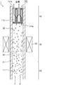
- FIG. 6 is a cross-sectional view schematically showing an embodiment of a droplet dispersion step and a carrier gas inflow step.
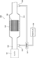
- FIG. 7 is an explanatory diagram of a collection efficiency measuring device.
- FIG. 8 is an explanatory diagram of a pressure loss measuring device.
- the honeycomb filter according to the first embodiment of the present invention A ceramic honeycomb substrate in which a large number of cells for circulating a fluid are arranged side by side in the longitudinal direction across a cell wall, and either the fluid inflow side or the fluid outflow side of the cell is sealed; Of the surface of the cell wall, a filtration layer formed on the surface of the cell wall of the cell in which the end portion on the fluid inflow side is opened and the end portion on the fluid outflow side is sealed; An SCR catalyst carried on the surface of the cell wall of the cell in which the end portion on the fluid inflow side is sealed and the end portion on the fluid outflow side is opened in the cell wall in which the filtration layer is formed; When the average pore diameter of the pores of the filtration layer is a ( ⁇ m) and the average particle diameter of the particles constituting the SCR catalyst is b ( ⁇ m), a portion satisfying a ⁇ b is included.
- the ceramic honeycomb substrate (ceramic block) is composed of a plurality of honeycomb fired bodies.
- a large number of cells included in the honeycomb fired body constituting the honeycomb filter are composed of large-capacity cells and small-capacity cells, and the cross-sectional area perpendicular to the longitudinal direction of the large-capacity cells is perpendicular to the longitudinal direction of the small-capacity cells. Larger than the cross-sectional area.
- the honeycomb filter according to the first embodiment of the present invention is obtained by forming a filtration layer on the surface of a cell wall of a ceramic honeycomb substrate including a honeycomb fired body.
- ceramic honeycomb substrate those having a filtration layer formed on the surface of the cell wall
- honeycomb filter those having the filtration layer formed on the cell wall are referred to as “honeycomb filter”.
- cross section of the honeycomb fired body when the cross section of the honeycomb fired body is simply indicated, it indicates a cross section perpendicular to the longitudinal direction of the honeycomb fired body. Similarly, when simply expressed as the cross-sectional area of the honeycomb fired body, it refers to the area of the cross section perpendicular to the longitudinal direction of the honeycomb fired body.
- FIG. 1 is a perspective view schematically showing an example of the honeycomb filter according to the first embodiment of the present invention.
- Fig.2 (a) is a perspective view which shows typically an example of the honeycomb fired body which comprises the honeycomb filter shown in FIG.
- FIG. 2B is a cross-sectional view taken along the line AA of the honeycomb fired body shown in FIG.
- FIG. 3 is a partially enlarged sectional view of the cell wall of the honeycomb fired body shown in FIGS. 2 (a) and 2 (b).
- honeycomb filter 100 a plurality of honeycomb fired bodies 110 are bound via an adhesive layer 101 to form a ceramic honeycomb substrate (ceramic block) 103, and this ceramic honeycomb substrate (ceramic block) ) On the outer periphery of 103, an outer peripheral coat layer 102 for preventing the leakage of exhaust gas is formed. In addition, the outer periphery coating layer should just be formed as needed.
- a honeycomb filter formed by binding a plurality of honeycomb fired bodies is also referred to as a collective honeycomb filter.
- the honeycomb fired body 110 constituting the honeycomb filter 100 will be described later, it is preferably a porous body made of silicon carbide or silicon-containing silicon carbide.
- a large number of cells 111a and 111b are arranged in the longitudinal direction (in the direction of arrow a in FIG. 2 (a)) across the cell wall 113. And an outer peripheral wall 114 is formed on the outer periphery thereof. One end of the cells 111a and 111b is sealed with a sealing material 112a or 112b.
- a filtration layer 115 is formed on the surface of the cell wall 113 of the honeycomb fired body 110.
- the SCR catalyst 116 is supported on the cell wall 113 of the honeycomb fired body 110.
- the filter layer 115 and the SCR catalyst 116 are not shown.
- the SCR catalyst 116 is not shown.
- a large-capacity cell 111a whose cross-sectional area perpendicular to the longitudinal direction is relatively larger than the small-capacity cell 111b, and a cross-section perpendicular to the longitudinal direction.
- small-capacity cells 111b whose area is relatively smaller than that of the large-capacity cell 111a.
- the shape of the cross section perpendicular to the longitudinal direction of the large capacity cell 111a is substantially octagonal, and the shape of the cross section perpendicular to the longitudinal direction of the small capacity cell 111b is substantially square.
- the large-capacity cell 111a is opened at the end portion on the first end face 117a side of the honeycomb fired body 110, and on the second end face 117b side. The end is sealed with a sealing material 112a.
- the small-capacity cell 111b the end portion on the second end face 117b side of the honeycomb fired body 110 is opened, and the end portion on the first end face 117a side is sealed with the sealing material 112b. Therefore, as shown in FIG. 2B, the exhaust gas G 1 flowing into the large-capacity cell 111a (in FIG.
- the exhaust gas is indicated by G 1 and the flow of the exhaust gas is indicated by an arrow) is always large.
- the small capacity cell 111b After passing through the cell wall 113 separating the capacity cell 111a and the small capacity cell 111b, the small capacity cell 111b flows out.
- the exhaust gas G 1 is passing through the cell walls 113, since the PM and the like in the exhaust gas is collected, the cell wall 113 that separates the large-volume cells 111a and small-volume cell 111b functions as a filter.
- gas such as exhaust gas can be circulated through the large-capacity cells 111a and the small-capacity cells 111b of the honeycomb fired body 110.
- a gas such as exhaust gas is circulated in the direction shown in FIG.
- the end of the honeycomb fired body 110 on the first end face 117a side (the end on the side where the small capacity cells 111b are sealed) is fluidized.
- the end on the inflow side is referred to as the end on the second end face 117b side of the honeycomb fired body 110 (the end on the side where the large-capacity cells 111a are sealed) is referred to as the end on the fluid outflow side.
- the large capacity cell 111a having an open end on the fluid inflow side is a cell 111a on the fluid inflow side
- the small capacity cell 111b having an end on the fluid outflow side is a cell on the fluid outflow side. 111b.
- the filtration layer is made of ceramic particles, preferably spherical ceramic particles.
- the ceramic particles forming the filtration layer are preferably made of a heat-resistant oxide.
- the heat-resistant oxide include alumina, silica, mullite, ceria, cordierite, zirconia, and titania. These may be used alone or in combination of two or more. Of the above heat-resistant oxides, alumina is preferable.
- the average particle size of the particles constituting the filtration layer is preferably 0.2 to 1.2 ⁇ m, more preferably 0.2 to 0.9 ⁇ m. Preferably, it is 0.5 to 0.8 ⁇ m.
- the average particle diameter of the particles constituting the filtration layer is less than 0.2 ⁇ m, the particles constituting the filtration layer are too small, and thus the filtration layer is hardly formed on the surface of the cell wall.
- the average particle diameter of the particles constituting the filtration layer is less than 0.2 ⁇ m, the particles constituting the filtration layer may enter the inside (pores) of the cell wall and block the pores. Loss may increase.
- the average particle diameter of the particles constituting the filtration layer exceeds 1.2 ⁇ m, the particles constituting the filtration layer are too large, so even if the filtration layer is formed, the pore size of the filtration layer is increased. Therefore, PM passes through the filtration layer and enters the pores of the cell wall, resulting in a “depth filtration” state in which PM is collected inside the cell wall, and the pressure loss increases.
- grains which comprise a filtration layer can be measured with the following method.
- a honeycomb fired body constituting the honeycomb filter is processed to prepare a sample of 10 mm ⁇ 10 mm ⁇ 10 mm.
- the surface of the sample is observed with a scanning electron microscope (SEM) at any one location of the prepared sample.
- SEM scanning electron microscope
- the particles constituting the filtration layer are set within one field of view.
- the observation conditions of SEM are acceleration voltage: 15.00 kV, working distance (WD): 15.00 mm, and magnification: 10,000 times.
- the particle diameters of all the particles in one field of view are visually measured.
- the average value of the particle diameters of all the particles measured within one field of view is defined as “the average particle diameter of the particles constituting the filtration layer”.
- a when the average pore diameter of the pores of the filtration layer is a, a is preferably 0.5 to 3.0 ⁇ m, and 0.7 to 2. It is more preferably 0 ⁇ m, and further preferably 1.0 to 1.9 ⁇ m. If a is less than 0.5 ⁇ m, the gas is difficult to permeate the filtration layer, and the permeation resistance increases. On the other hand, when a exceeds 3.0 ⁇ m, it becomes difficult for PM to pass through the filtration layer, so that it is difficult to obtain sufficient PM collection efficiency.
- the average pore diameter a of the pores of the filtration layer can be measured by the following method.
- the honeycomb fired body constituting the honeycomb filter is processed to produce a 10 mm ⁇ 10 mm ⁇ 10 mm sample.
- the surface of the sample is observed with a scanning electron microscope (SEM) at any one location of the prepared sample.
- SEM scanning electron microscope
- the observation conditions of SEM are acceleration voltage: 15.00 kV, working distance (WD): 15.00 mm, and magnification: 10,000 times.
- the obtained SEM photograph is binarized, and the diameter of a circle inscribed in the gap between the particles is measured at 10 or more locations.
- the measured average value of the diameter of the inscribed circle is defined as “average pore diameter a of pores of the filtration layer”.
- the filtration layer may contain hollow particles.
- the thickness of the filtration layer is preferably 3 to 60 ⁇ m, more preferably 5 to 40 ⁇ m, and still more preferably 10 to 25 ⁇ m.
- the thickness of the filtration layer is less than 3 ⁇ m, the filtration layer is too thin, so that PM is hardly collected.
- the thickness of the filtration layer exceeds 60 ⁇ m, the filtration layer is too thick, and the pressure loss is likely to increase.
- it is preferable that the thickness of the filtration layer is constant.
- FIG. 4 is a schematic diagram for explaining a method of measuring the thickness of the filtration layer.
- the honeycomb fired body constituting the honeycomb filter is processed to produce a 10 mm ⁇ 10 mm ⁇ 10 mm sample.
- the cell cross section is observed with a scanning electron microscope (SEM) at any one location of the prepared sample.
- SEM scanning electron microscope
- the observation conditions of SEM are acceleration voltage: 15.00 kV, working distance (WD): 15.00 mm, and magnification: 500 to 1000 times.
- FIG. 4 for the sake of easy understanding, a schematic diagram is shown instead of an actual SEM photograph.
- FIG. 4 for the sake of easy understanding, a schematic diagram is shown instead of an actual SEM photograph.
- the filtration layer is formed only on the surface of the cell wall of the cell in which the end on the fluid inflow side is opened and the end on the fluid outflow side is sealed. . Since the exhaust gas flows into the cell from the fluid inflow side of the honeycomb filter, a large amount of PM in the exhaust gas accumulates on the cell wall of the cell where the end on the fluid inflow side is opened and the end on the fluid outflow side is sealed. Is done. Therefore, when the filtration layer is formed only on the surface of the cell wall of the cell in which the end on the fluid inflow side is opened and the end on the fluid outflow side is sealed, PM is collected by the filtration layer. Therefore, depth filtration can be prevented.
- the filtration layer is formed on the entire surface of the cell wall of the cell in which the end on the fluid inflow side is opened and the end on the fluid outflow side is sealed. However, there may be a portion where the filtration layer is not formed on a part of the surface of the cell wall.
- the SCR catalyst is also called a selective reduction type NOx catalyst, and reduces and purifies NOx in exhaust gas using ammonia.
- the SCR catalyst has a function of adsorbing urea and ammonia.
- the SCR catalyst is preferably zeolite.
- the supported amount of the SCR catalyst is preferably 80 to 200 g / L, more preferably 100 to 200 g / L, and more preferably 100 to 150 g / L. More preferably.
- the supported amount of SCR catalyst is 80 to 200 g / L, NOx in the exhaust gas can be sufficiently purified when the honeycomb filter is used in a urea SCR device.
- the supported amount of the SCR catalyst is less than 80 g / L, the NOx purification performance as a honeycomb filter for the urea SCR device is not sufficient.
- the loading amount of the SCR catalyst exceeds 200 g / L, the SCR catalyst closes the cell, and the pressure loss is likely to increase even when PM is not deposited.
- the loading amount of the SCR catalyst means the weight of the SCR catalyst per liter of the apparent volume of the honeycomb filter.
- the apparent volume of the honeycomb filter includes the volume of the adhesive layer and / or the outer peripheral coat layer.
- b when the average particle diameter of the particles constituting the SCR catalyst is b, b is preferably 0.7 to 5.0 ⁇ m, and 2.0 to 4 The thickness is more preferably 0.0 ⁇ m, and even more preferably 2.1 to 4.0 ⁇ m.
- b is less than 0.7 ⁇ m, the particles constituting the SCR catalyst are too small, and the particles are likely to clog the filtration layer.
- b exceeds 5.0 ⁇ m, the particles constituting the SCR catalyst are less likely to be clogged in the filtration layer, but the specific surface area of the particles is small, so that it is difficult to obtain a sufficient NOx purification rate.
- the average particle diameter b of the particles constituting the SCR catalyst can be measured by the same method as the average particle diameter of the particles constituting the filtration layer. When the average particle diameter b is measured, SEM observation may be performed so that the particles constituting the SCR catalyst fall within one field of view. In addition, the average particle diameter b can be substituted with an average particle diameter obtained from particles (for example, zeolite particles contained in a zeolite slurry described later) constituting the SCR catalyst before being supported on the ceramic honeycomb substrate. .
- the SCR catalyst is a cell wall in which a filtration layer is formed, the end of the fluid inflow side is sealed, and the end of the fluid outflow side is opened. It is carried on the surface of the cell wall.
- the SCR catalyst is supported on the entire surface of the cell wall of the cell in which the end on the fluid inflow side is sealed and the end on the fluid outflow side is opened. However, it is possible that a part of the surface of the cell wall does not support the SCR catalyst.
- the SCR catalyst may be further supported on the pores of the cell walls of the ceramic honeycomb substrate.
- the SCR catalyst is further supported on the surface of the cell wall of the cell in which the end on the fluid inflow side is opened and the end on the fluid outflow side is sealed. Also good.
- the SCR catalyst has an end on the fluid inflow side that is open and an end on the fluid inflow side is sealed from the surface side of the cell wall of the cell that is sealed at the end on the fluid outflow side. It is preferable that a large number of the side ends are supported on the surface side of the cell wall of the opened cell. In this case, contact between the collected PM and the SCR catalyst can be prevented.
- the SCR catalyst is preferably not supported on the surface of the filtration layer. In this case, the deterioration of the SCR catalyst due to heat can be suppressed when the regeneration process for burning PM is performed.
- the honeycomb filter according to the first embodiment of the present invention includes a portion satisfying a ⁇ b, where a is the average pore diameter of the pores of the filtration layer and b is the average particle diameter of the particles constituting the SCR catalyst. It is characterized by being.
- the entire honeycomb filter may not satisfy a ⁇ b, and a part of the honeycomb filter only needs to satisfy a ⁇ b.
- the portion satisfying a ⁇ b may be 60% or less of the whole honeycomb filter or 40% or less.
- the portion satisfying a ⁇ b is preferably 20% or more of the whole honeycomb filter, and more preferably 30% or more.
- the porosity of the cell wall is preferably 55 to 70%.
- the porosity of the cell wall of the ceramic honeycomb substrate is 55 to 70%, a large amount of SCR catalyst can be supported on the cell wall.
- the porosity of the cell wall is less than 55%, when a large amount of the SCR catalyst is supported on the ceramic honeycomb substrate, the SCR catalyst is clogged in the pore portion of the cell wall, and the exhaust gas does not easily pass through the cell wall. The exhaust gas is less likely to diffuse and the action of the SCR catalyst is not sufficiently exhibited.
- the porosity of the cell wall exceeds 70%, the strength of the ceramic honeycomb substrate tends to decrease.
- the average pore diameter of the cell wall is preferably 15 to 30 ⁇ m.
- the average pore diameter of the cell wall is less than 15 ⁇ m, the pressure loss after the SCR catalyst is supported on the cell wall tends to increase.
- the average pore diameter of the cell wall exceeds 30 ⁇ m, it becomes difficult to form a filtration layer on the surface of the cell wall.
- the porosity and pore diameter can be measured by a conventionally known mercury intrusion method.
- the thickness of the cell wall is preferably 0.12 to 0.40 mm, and more preferably 0.20 to 0.30 mm.
- the cell wall thickness is less than 0.12 mm, the cell wall thickness becomes thin, and the strength of the honeycomb fired body cannot be maintained.
- the thickness of the cell wall exceeds 0.40 mm, the pressure loss of the honeycomb structure tends to increase.
- the thickness of a cell wall means the thickness between cells.
- the cell density in the cross section perpendicular to the longitudinal direction of the honeycomb fired body is not particularly limited, but a preferable lower limit is 31.0 cells / cm 2 (200 cells / inch 2). ), A preferred upper limit is 93.0 pieces / cm 2 (600 pieces / inch 2 ), a more preferred lower limit is 38.8 pieces / cm 2 (250 pieces / inch 2 ), and a more preferred upper limit is 77.5 pieces. / Cm 2 (500 pieces / inch 2 ).
- examples of the shape of the cross section perpendicular to the longitudinal direction of the large-capacity cell and the small-capacity cell included in the honeycomb fired body include the following shapes.
- 5 (a), 5 (b) and 5 (c) are side views schematically showing an example of the cell structure of the honeycomb fired body constituting the honeycomb filter according to the first embodiment of the present invention.
- the filtration layer is not illustrated in FIGS. 5A, 5B, and 5C.
- the shape of the cross section perpendicular to the longitudinal direction of the large capacity cell 121a is substantially octagonal, and the shape of the cross section perpendicular to the longitudinal direction of the small capacity cell 121b is substantially rectangular.
- the large capacity cells 121a and the small capacity cells 121b are alternately arranged.
- the shape of the cross section perpendicular to the longitudinal direction of the large capacity cell 131a is substantially octagonal, and the shape of the cross section perpendicular to the longitudinal direction of the small capacity cell 131b.
- the honeycomb fired body 120 shown in FIG. 5 (a) and the honeycomb fired body 130 shown in FIG. 5 (b) have a cross section perpendicular to the longitudinal direction of the large capacity cell with respect to the area of the cross section perpendicular to the longitudinal direction of the small capacity cell.
- the area ratio of the areas is different. Further, in the honeycomb fired body 140 shown in FIG.
- the cross-sectional shape perpendicular to the longitudinal direction of the large-capacity cell 141a is substantially square, and the cross-sectional shape perpendicular to the longitudinal direction of the small-capacity cell 141b is substantially
- the large-capacity cells 141a and the small-capacity cells 141b are alternately arranged.
- the area ratio of the area of the cross section perpendicular to the longitudinal direction of the large capacity cell to the area of the cross section perpendicular to the longitudinal direction of the small capacity cell is preferably 1.4 to 2.8, and more preferably 1.5 to 2.4.
- honeycomb filter according to the first embodiment of the present invention Using a ceramic powder, a porous honeycomb fired body in which a large number of cells are arranged in parallel in the longitudinal direction across a cell wall, and either the fluid inflow side or the fluid outflow side of the cell is sealed.
- a honeycomb fired body manufacturing process to be manufactured A filtration layer forming step of forming a filtration layer on the surface of the cell wall; A catalyst application step of supporting the SCR catalyst on the cell wall,
- the filtration layer forming step includes A droplet dispersion step of dispersing droplets containing raw materials of ceramic particles in a carrier gas;
- a carrier gas inflow step for allowing the carrier gas to flow into a cell in which an end on the fluid inflow side is opened and an end on the fluid outflow side is sealed,
- the SCR catalyst is supported on the cell wall by introducing the SCR catalyst into a cell in which the end portion on the fluid inflow side is sealed and the end portion on the fluid outflow side is opened.
- a ceramic honeycomb substrate including a honeycomb fired body is manufactured, and a filtration layer is formed on the surface of the cell wall of the ceramic honeycomb substrate.
- the SCR catalyst is supported on the formed cell wall.
- the filtration layer forming step and the catalyst applying step will be described.
- the case where the material constituting the filtration layer is a heat-resistant oxide will be described as an example.
- the process for producing the ceramic honeycomb substrate including the honeycomb fired body will be described later.
- FIG. 6 is a cross-sectional view schematically showing an embodiment of a droplet dispersion step and a carrier gas inflow step.
- FIG. 6 shows a carrier gas inflow device 1 that is a device for causing a carrier gas to flow into the cells of the ceramic honeycomb substrate.
- the carrier gas inflow device 1 includes a droplet dispersion unit 20 that disperses droplets in the carrier gas, a piping unit 30 through which the carrier gas in which the droplets are dispersed passes, and an inflow unit that flows the carrier gas into the cells of the ceramic honeycomb substrate. 40.
- the droplet dispersion step and the carrier gas inflow step are performed using the carrier gas inflow device 1 will be described.
- the carrier gas F flows from the lower side to the upper side in FIG.
- the carrier gas F is introduced from below the carrier gas inflow device 1, and is discharged from above the inflow portion 40 through the droplet dispersion portion 20, the piping portion 30, and the inflow portion 40.
- the carrier gas F is pressurized from the lower side to the upper side in FIG. 6 by the pressure difference generated by the pressurization from the lower side of the carrier gas inflow device or the suction from the upper side of the carrier gas inflow device. Flows upward in 1.
- a gas that does not react by heating up to 800 ° C. and does not react with the components in the droplets dispersed in the carrier gas is used.
- the carrier gas include gases such as air, nitrogen, and argon.
- an oxide-containing solution filled in a tank (not shown) is formed into droplets 11 by spraying and dispersed in the carrier gas F.
- the oxide-containing solution is a concept including a solution containing a heat-resistant oxide precursor in which a heat-resistant oxide is formed by heating, or a slurry containing heat-resistant oxide particles.
- the heat-resistant oxide precursor means a compound derived from a heat-resistant oxide by heating. Examples thereof include metal hydroxides, carbonates, nitrates, and hydrates constituting the heat-resistant oxide.
- the slurry containing heat-resistant oxide particles is a solution in which heat-resistant oxide particles are suspended in water.
- the droplets 11 dispersed in the carrier gas F ride on the carrier gas F and flow above the carrier gas inflow device 1 and pass through the piping part 30.
- the pipe part 30 of the carrier gas inflow device 1 is a pipe through which the carrier gas F in which the droplets 11 are dispersed passes.
- the passage 32 through which the carrier gas F passes in the pipe portion 30 is a space surrounded by the pipe wall 31 of the pipe.
- a heating mechanism 33 is provided in the piping part 30.
- An example of the heating mechanism 33 is an electric heater.
- the pipe wall 31 is heated using the heating mechanism 33, and the carrier gas F in which the droplets 11 are dispersed is allowed to pass through. And it is preferable to heat the carrier gas F which passes the piping part 30, and to heat the droplet 11 disperse
- FIG. 6 When the droplet 11 is heated, the liquid component contained in the droplet evaporates to form spherical ceramic particles 12. In FIG. 6, the spherical ceramic particles 12 are indicated by white circles.
- the heat-resistant oxide precursor is contained in the droplet, the heat-resistant oxide precursor becomes a heat-resistant oxide (spherical ceramic particles) by heating the carrier gas.
- the pipe wall 31 is heated to 100 to 800 ° C. using the heating mechanism 33 and the carrier gas F in which the droplets 11 are dispersed is allowed to pass for 0.1 to 3.0 seconds. If the temperature of the heated pipe is less than 100 ° C. and the time for allowing the carrier gas to pass through the pipe is less than 0.1 seconds, it becomes difficult to sufficiently evaporate the water in the droplets. On the other hand, if the temperature of the heated pipe exceeds 800 ° C. and the time for passing the carrier gas through the pipe exceeds 3.0 seconds, the energy required for manufacturing the honeycomb filter becomes too large. The manufacturing efficiency of the honeycomb filter is reduced.
- the length of the pipe is not particularly limited, but is preferably 500 to 3000 mm. If the length of the pipe is less than 500 mm, it becomes difficult to sufficiently evaporate the water in the droplets even if the speed of passing the carrier gas through the pipe is slowed. On the other hand, if the length of the pipe exceeds 3000 mm, the apparatus for manufacturing the honeycomb filter becomes too large, and the manufacturing efficiency of the honeycomb filter is lowered.
- the spherical ceramic particles 12 ride on the flow of the carrier gas F and flow above the carrier gas inflow device 1, and flow into the cells of the ceramic honeycomb substrate 103 at the inflow portion 40.
- a ceramic block in which a plurality of honeycomb fired bodies are bound through an adhesive layer is used as the ceramic honeycomb substrate.
- the ceramic honeycomb substrate 103 is arranged at the upper part of the carrier gas inflow device 1 so as to close the outlet of the carrier gas inflow device 1. Therefore, the carrier gas F always flows into the ceramic honeycomb substrate 103.
- FIG. 6 schematically shows a cross section of the honeycomb fired body constituting the ceramic block (a cross section similar to that shown in FIG. 2B) as a cross section of the ceramic honeycomb substrate 103.
- the end portion of the cell 111a on the fluid inflow side is open, and the cell 111b on the fluid outflow side is sealed. Therefore, the carrier gas F flows into the ceramic honeycomb substrate 103 from the opening of the cell 111a on the fluid inflow side.
- the carrier gas F in which the spherical ceramic particles 12 are dispersed flows into the cell 111 a on the fluid inflow side of the ceramic honeycomb substrate 103, the spherical ceramic particles 12 are deposited on the surface of the cell wall 113 of the ceramic honeycomb substrate 103.
- the ceramic honeycomb substrate 103 is heated to 100 to 800 ° C. and the carrier gas F is allowed to flow into the heated cell.
- the ceramic honeycomb substrate 103 is heated to 100 to 800 ° C., even if the liquid component remains in the spherical ceramic particles 12, the liquid component evaporates, and the surface of the cell wall is in a dry powder state. To deposit.
- the carrier gas F flows into the inside of the ceramic honeycomb substrate 103 from the opening of the cell 111a on the fluid inflow side, passes through the cell wall 113 of the ceramic honeycomb substrate 103, and flows out from the opening of the cell 111b on the fluid outflow side.
- the carrier gas inflow process is performed by such a procedure.
- the spherical ceramic particles can be deposited on the surface of the cell wall by the carrier gas inflow process.
- the ceramic honeycomb substrate it is preferable to perform a heating process of the ceramic honeycomb substrate. It is preferable to heat the ceramic honeycomb substrate on which the spherical ceramic particles are adhered to the cell walls through the carrier gas inflow process at a furnace temperature of 900 to 1500 ° C. using a heating furnace.
- the heating atmosphere is preferably an air atmosphere, a nitrogen atmosphere, or an argon atmosphere.
- the spherical ceramic particles adhering to the surface of the cell wall cause heat shrinkage by heat sintering and firmly adhere to the surface of the cell wall.
- a filtration layer can be formed on the surface of the cell wall.
- the step of heating the carrier gas drying step
- the SCR catalyst is supported on the cell wall by introducing the SCR catalyst into the cell in which the end on the fluid inflow side is sealed and the end on the fluid outflow side is opened.
- Examples of the method for supporting the SCR catalyst on the cell wall include a method in which the ceramic honeycomb substrate is immersed in a slurry containing the SCR catalyst and then heated by heating.
- the amount of the SCR catalyst supported can be adjusted by, for example, a method of repeating the step of immersing the ceramic honeycomb substrate in the slurry and the step of heating, or a method of changing the slurry concentration.
- the average particle diameter b of the particles constituting the SCR catalyst can be adjusted by controlling the particle size of the particles constituting the SCR catalyst contained in the slurry.
- the particle size of the particles constituting the SCR catalyst contained in the slurry is adjusted so that the average particle size b of the particles constituting the SCR catalyst is larger than the average pore size a of the pores of the filter layer that has been obtained in advance. do it.
- the other end is sealed only in the cell (large capacity cell) on the fluid inflow side, and then the ceramic honeycomb substrate is immersed in the slurry containing the SCR catalyst.
- the cell wall forming the fluid inflow side cell Only after the catalyst is attached to the cell wall forming one cell in the same procedure as the procedure for supporting the SCR catalyst, the SCR catalyst is also supported on the cell wall forming the other cell. Changing the immersion time of the ceramic honeycomb substrate in the slurry containing the catalyst, changing the concentration of the slurry, or increasing the particle size of the catalyst in the slurry, and injecting the slurry into the cell on the fluid inflow side And a method of changing the concentration by air blow after the slurry is attached.
- the ceramic honeycomb substrate produced below is a ceramic block in which a plurality of honeycomb fired bodies are bundled through an adhesive layer.
- silicon carbide used as the ceramic powder.
- a forming step for producing a honeycomb formed body by extruding a wet mixture containing a ceramic powder and a binder is performed. Specifically, first, a wet mixture for manufacturing a honeycomb formed body is prepared by mixing silicon carbide powder having different average particle sizes as ceramic powder, an organic binder, a liquid plasticizer, a lubricant, and water. To prepare.
- a honeycomb formed body having a predetermined shape.
- a honeycomb formed body is manufactured using a mold that has a cross-sectional shape having a cell structure (cell shape and cell arrangement) shown in FIGS. 2 (a) and 2 (b).
- the honeycomb formed body is cut to a predetermined length, dried using a microwave dryer, hot air dryer, dielectric dryer, vacuum dryer, vacuum dryer, freeze dryer, etc.
- a sealing step of filling the cell with a sealing material paste as a sealing material and sealing the cell is performed.
- the wet mixture can be used as the sealing material paste.
- the degreased honeycomb formed body is conveyed to a firing furnace, and the firing step is performed.
- a honeycomb fired body as shown in FIGS. 2A and 2B is manufactured.
- the sealing material paste with which the edge part of the cell was filled is baked by heating and becomes a sealing material.
- the conditions currently used when manufacturing a honeycomb fired body can be applied to the conditions of a cutting process, a drying process, a sealing process, a degreasing process, and a firing process.
- a bundling process is performed in which a plurality of honeycomb fired bodies are sequentially stacked and bonded via an adhesive paste on a support stand to produce a honeycomb aggregate in which a plurality of honeycomb fired bodies are stacked.
- the adhesive paste for example, a paste made of an inorganic binder, an organic binder, and inorganic particles is used.
- the adhesive paste may further contain inorganic fibers and / or whiskers.
- honeycomb aggregate is heated and the adhesive paste is heated and solidified to form an adhesive layer, thereby producing a quadrangular columnar ceramic block.
- the conditions for heating and solidifying the adhesive paste the conditions conventionally used when producing a honeycomb filter can be applied.
- a cutting process for cutting the ceramic block is performed. Specifically, a ceramic block whose outer periphery is processed into a substantially cylindrical shape is manufactured by cutting the outer periphery of the ceramic block using a diamond cutter.
- An outer peripheral coating layer forming step is performed in which an outer peripheral coating material paste is applied to the outer peripheral surface of the substantially cylindrical ceramic block, and dried and solidified to form an outer peripheral coating layer.
- the said adhesive paste can be used as an outer periphery coating material paste.
- the outer peripheral coat layer is not necessarily provided, and may be provided as necessary.
- honeycomb filter which concerns on 1st embodiment of this invention is producible by performing the filtration layer formation process and catalyst provision process which were mentioned above with respect to the ceramic honeycomb base material.
- the honeycomb filter of the present embodiment includes a portion satisfying a ⁇ b, where a is the average pore diameter of the pores of the filtration layer and b is the average particle diameter of the particles constituting the SCR catalyst. It is said.
- a is the average pore diameter of the pores of the filtration layer
- b is the average particle diameter of the particles constituting the SCR catalyst.
- a carrier gas containing ceramic particles formed in the drying step and the like described later is caused to flow into the cell from the fluid inflow side. Therefore, ceramic particles are deposited on the surface of the cell wall of the cell in which the end portion on the fluid inflow side is opened and the end portion on the fluid outflow side is sealed, and a filtration layer is formed.
- the SCR catalyst is introduced into the cell from the fluid outflow side, that is, the side opposite to the side into which the carrier gas is introduced in the carrier gas inflow step.
- the direction in which the carrier gas is introduced in the carrier gas inflow process is opposite to the direction in which the SCR catalyst is introduced in the catalyst application process. Accordingly, the SCR catalyst is supported only on the cell wall of the cell wall and the filtration layer, or is supported on both the cell wall and the filtration layer, and the amount of the SCR catalyst supported on the cell wall is reduced.
- the amount per unit volume is larger than the amount of the SCR catalyst supported on the filtration layer. Therefore, the amount of the SCR catalyst that is far from the collected PM can be increased. That is, when the regeneration process for burning PM is performed, the amount of the SCR catalyst that does not deteriorate due to heat can be increased, so that the NOx purification function can be ensured over a long period of time.
- the honeycomb filter manufacturing method of the present embodiment includes a portion satisfying a ⁇ b, where a is the average pore diameter of the pores of the filtration layer and b is the average particle diameter of the particles constituting the SCR catalyst.
- a honeycomb filter is manufactured. Therefore, the SCR catalyst can be prevented from clogging the filtration layer in the catalyst application step. As a result, a honeycomb filter with low pressure loss can be manufactured.
- Example 2 Examples of the honeycomb filter and the method for manufacturing the honeycomb filter according to the first embodiment of the present invention will be described below more specifically. In addition, this invention is not limited only to these Examples.
- Example 1 (Production of ceramic honeycomb substrate) First, 54.6% by weight of a coarse powder of silicon carbide having an average particle diameter of 22 ⁇ m and 23.4% by weight of a fine powder of silicon carbide having an average particle diameter of 0.5 ⁇ m were mixed. An organic binder (methylcellulose) 4.3 wt%, a lubricant (Unilube made by NOF Corporation) 2.6 wt%, glycerin 1.2 wt%, and water 13.9 wt% are added and kneaded to obtain a wet mixture. After being obtained, a molding step of extrusion molding was performed. In this step, a raw honeycomb molded body having the same shape as the honeycomb fired body 110 shown in FIG. 2A and having no cell plugged was produced.
- a lubricant Unilube made by NOF Corporation
- the raw honeycomb formed body was dried using a microwave dryer, thereby manufacturing a dried body of the honeycomb formed body.
- the sealing material paste was filled in predetermined cells of the dried honeycomb molded body to seal the cells.
- the wet mixture was used as a sealing material paste.
- the dried honeycomb molded body filled with the plug paste was again dried using a dryer.
- the manufactured honeycomb fired body has a height of 34.3 mm ⁇ a width of 34.3 mm ⁇ a length of 150 mm, an average pore diameter of 24 ⁇ m, a porosity of 64%, and the number of cells (cell density) of 54.2 cells / cm 2 ( 350 cells / inch 2 ) and the cell wall thickness was 0.28 mm (11 mil).
- honeycomb fired bodies By applying an adhesive paste between the honeycomb fired bodies obtained by the above process to form an adhesive paste layer, and heating and solidifying the adhesive paste layer to form an adhesive layer, 16 honeycomb fired bodies are obtained. A substantially prismatic ceramic block formed by binding through an adhesive layer was produced.
- As the adhesive paste 30% by weight of alumina fibers having an average fiber length of 20 ⁇ m, 21% by weight of silicon carbide particles having an average particle diameter of 0.6 ⁇ m, 15% by weight of silica sol, 5.6% by weight of carboxymethylcellulose, and water 28 An adhesive paste containing 4% by weight was used.
- a cylindrical ceramic block having a diameter of 142 mm was prepared by cutting the outer periphery of the prismatic ceramic block using a diamond cutter.
- the outer peripheral coating material paste was applied to the outer peripheral surface of the columnar ceramic block, and the outer peripheral coating material paste was heated and solidified at 120 ° C. to form an outer peripheral coating layer on the outer peripheral portion of the ceramic block.
- the paste similar to the said adhesive material paste was used as the said outer periphery coating material paste.
- a filter layer was formed on the ceramic honeycomb substrate using the carrier gas inflow device shown in FIG. As shown in FIG. 6, a ceramic honeycomb substrate was disposed above the carrier gas inflow device. At this time, the ceramic honeycomb substrate was disposed with the opening of a large-capacity cell as a cell on the fluid inflow side facing downward of the carrier gas inflow device.
- a solution containing boehmite which is a heat-resistant oxide precursor was prepared.
- the concentration of boehmite was 3.8 mol / L (solid content concentration: 20% by weight). Then, the droplets containing boehmite were dispersed in the carrier gas by spraying.
- the temperature of the wall of the pipe of the carrier gas inflow device is heated to 200 ° C., and the carrier gas is flowed at a flow rate of 4.6 mm / sec toward the upper side (ceramic honeycomb substrate side) of the carrier gas inflow device.
- the water in the droplets dispersed therein was evaporated.
- the length of the pipe was 1200 mm.
- the carrier gas in which the spherical alumina particles were dispersed was allowed to flow into the cells of the ceramic honeycomb substrate, and 5 g / L of spherical alumina particles were adhered to the surface of the cell walls. Thereafter, the ceramic honeycomb substrate was taken out from the carrier gas inflow device and heated in a firing furnace at 1350 ° C. for 3 hours in an air atmosphere. Through the above process, a filtration layer made of alumina particles was formed on the surface of the cell wall.
- ⁇ -type zeolite powder ion-exchanged with iron ions was mixed with a sufficient amount of water, and further pulverized with a ball mill at 90 min ⁇ 1 to prepare a zeolite slurry.
- the particle diameter of the zeolite was adjusted by changing the particle diameter of the raw material powder and the pulverization time.
- a ceramic honeycomb substrate having a filtration layer formed on the surface of the cell wall was immersed with the opening of a small-capacity cell as a cell on the fluid outflow side facing downward, and held for 1 minute. Then, the drying process which heats this ceramic honeycomb base material for 1 hour at 110 degreeC was performed, and also the baking process for baking for 1 hour at 700 degreeC was performed, and the SCR catalyst was carry
- Example 1 When preparing the zeolite slurry, a honeycomb filter was produced in the same manner as in Example 1 except that the pulverization time was longer than that in Example 1 to make the zeolite particle size smaller than that in Example 1.
- FIG. 7 is an explanatory diagram of a collection efficiency measuring device.
- the collection efficiency measuring device 530 includes a 1.6 L (liter) diesel engine 531, an exhaust gas pipe 532 that distributes exhaust gas from the engine 531, and a honeycomb filter 100 that is connected to the exhaust gas pipe 532 and wound with an alumina mat 533.
- the metal casing 534 to be fixed, the sampler 535 that samples the exhaust gas before flowing through the honeycomb filter 100, the sampler 536 that samples the exhaust gas after flowing through the honeycomb filter 100, and the exhaust gas sampled by the samplers 535 and 536 is diluted.
- Scanning mobility particle size analyzer (Scanning Mobility P) equipped with a diluter 537 and a PM counter 538 (aggregated particle counter 3022A-S manufactured by TSI) for measuring the amount of PM contained in the diluted exhaust gas rticle Sizer SMPS) is configured as.
- the NOx purification rate was measured for each honeycomb filter.
- one honeycomb fired body (34.3 mm ⁇ 34.3 mm ⁇ 150 mm) was cut out from the honeycomb filter of Example 1 and Comparative Example 1 by using a diamond cutter, and the cut honeycomb The fired body was further cut to prepare a cylindrical short body of ⁇ 1 inch (25.4 mm) ⁇ 3 inches (76.2 mm). In the produced short body, either one end of the cell was sealed, and this short body was used as a sample for NOx purification rate measurement.
- the NOx purification rate was measured using a NOx purification rate measuring device (Catalyst evaluation device SIGU-2000 manufactured by Horiba, Ltd.).
- the NOx purification rate measuring device is composed of a gas generation part and a reaction part, and the pseudo exhaust gas and ammonia generated in the gas generation part are circulated through the reaction part in which a sample for NOx purification rate measurement is set.
- the above composition was obtained by adjusting the flow rate of each gas using a flow rate controller. Further, the temperature of the reaction part was kept constant at 150 ° C.
- the space velocity (SV) was set to 70000 hr ⁇ 1 as a condition for the zeolite to contact the pseudo exhaust gas and ammonia.
- the NOx purification rate was measured.
- NOx purification rate (%) [(N 0 ⁇ N 1 ) / N 0 ] ⁇ 100 The obtained measurement results are shown in Table 1.
- FIG. 8 is an explanatory diagram of a pressure loss measuring device.
- the pressure loss measuring device 510 can detect the pressure before and after the honeycomb filter 100 by disposing the honeycomb filter 100 in the metal casing 513 in the exhaust gas pipe 512 of a 1.6 L (liter) diesel engine 511.
- a pressure gauge 514 is attached so that The engine 511 was operated at a torque of 50 Nm and a rotation speed of 3000 rpm, and the differential pressure in a state where PM was not deposited on the honeycomb filter 100, that is, the initial pressure loss was measured.
- the obtained measurement results are shown in Table 1.
- the average pore diameter a of the pores of the filtration layer in the honeycomb filter of Example 1 and Comparative Example 1, the average particle diameter b of the particles constituting the SCR catalyst, the collection efficiency, the NOx purification rate, and the initial pressure loss are summarized. It is shown in Table 1 below.
- the NOx purification rate of the honeycomb filter of Comparative Example 1 is a low value of 48%, whereas the NOx purification rate of the honeycomb filter of Example 1 is a high value of 55%.
- the average pore diameter “a” of the pores of the filtration layer is larger than the average particle diameter “b” of the particles (zeolite particles) constituting the SCR catalyst. Therefore, it is considered that a part of the zeolite particles enters the filtration layer. As a result, the zeolite particles that have entered the filtration layer are exposed to high temperatures and deteriorate, and the NOx purification rate decreases.
- the honeycomb filter of Example 1 since the average pore diameter a is smaller than the average particle diameter b, it is considered that the zeolite particles hardly enter the filtration layer. Therefore, a high NOx purification rate can be maintained.
- the initial pressure loss in the honeycomb filter of Comparative Example 1 was a high value of 15 kPa, whereas the initial pressure loss rate in the honeycomb filter of Example 1 was a low value of 10 kPa.
- the honeycomb filter of Example 1 since the average pore diameter a is smaller than the average particle diameter b, it is considered that the zeolite particles are less likely to clog the filtration layer. For this reason, it is considered that an increase in pressure loss can be prevented.
- the honeycomb filter of Example 1 by including a portion where the average pore diameter a is smaller than the average particle diameter b, it is excellent in PM collection efficiency and NOx purification rate, and suppresses an increase in pressure loss. Can do.
- the filtration layer is formed only on the surface of the cell wall of the cell in which the end portion on the fluid inflow side is opened and the end portion on the fluid outflow side is sealed.
- the filtration layer has an opening at the end on the fluid inflow side and a surface of the cell wall of the cell where the end on the fluid outflow side is sealed, The end portion on the fluid inflow side may be sealed, and the end portion on the fluid outflow side may be formed on the surface of the cell wall of the cell.
- Such a honeycomb filter can be manufactured by immersing the ceramic honeycomb substrate in a slurry containing spherical ceramic particles prepared in advance and then heating.
- the droplets may contain heat-resistant oxide particles as a raw material for the ceramic particles.
- the moisture in the droplets can be removed by heating the carrier gas to obtain heat-resistant oxide particles.
- grains of a heat resistant oxide can be formed by flowing the particle
- the filtration layer comprised of the particles of the heat-resistant oxide can also be formed by removing the moisture in the droplets after flowing the droplet containing the heat-resistant oxide particles into the cell.
- the shape of the cross section perpendicular to the longitudinal direction of the cells of the honeycomb fired body constituting the honeycomb filter may be all equal, or at one end face of the honeycomb fired body.
- the cross-sectional areas perpendicular to the longitudinal direction of the sealed cell and the opened cell may be equal to each other.
- the ceramic honeycomb substrate may be composed of one honeycomb fired body.
- a honeycomb filter made of one honeycomb fired body is also referred to as an integral honeycomb filter.
- cordierite or aluminum titanate can be used as the main constituent material of the integral honeycomb filter.
- the shape of the cross section perpendicular to the longitudinal direction of the honeycomb fired body of each cell of the honeycomb fired body is not limited to a substantially square shape, for example, a substantially circular shape or a substantially elliptical shape. Any shape such as a substantially pentagon, a substantially hexagon, a substantially trapezoid, or a substantially octagon may be used. Various shapes may be mixed.
- the filtration layer is formed on the surface of the cell wall of the ceramic honeycomb substrate, the SCR catalyst is supported on the cell wall of the ceramic honeycomb substrate, and the filtration layer has
- the average pore diameter of the pores is a ( ⁇ m) and the average particle diameter of the particles constituting the SCR catalyst is b ( ⁇ m)
- the essential components include various configurations described in detail in the first embodiment and the other embodiments (for example, the configuration of the filtration layer, the method of forming the filtration layer, the cell structure of the honeycomb fired body, the manufacture of the honeycomb filter) Desired effects can be obtained by appropriately combining the steps and the like.
Abstract
La présente invention concerne un filtre en nid d'abeilles comprenant : un matériau céramique de base en nid d'abeilles comportant une pluralité de cellules, à travers lesquelles un fluide peut s'écouler, alignées dans la direction longitudinale et séparées par des parois, ledit matériau de base ayant une section terminale scellée du côté de l'entrée du fluide ou du côté de sortie du fluide des cellules ; une couche filtrante formée, parmi les surfaces des parois des cellules, sur la surface des parois des cellules ayant la section terminale ouverte du côté de l'entrée du fluide et la section terminale scellée du côté de sortie du fluide ; et, dans les parois des cellules sur lesquelles la couche filtrante est formée, un catalyseur de réduction catalytique sélective supporté par la surface des parois des cellules ayant la section terminale scellée du côté de l'entrée du fluide et la section terminale ouverte du côté de sortie du fluide. Le filtre en nid d'abeilles est caractérisé en ce qu'il comprend une section pour laquelle a < b, où a (µm) est le diamètre moyen des pores dans la couche filtrante et b (µm) est le diamètre moyen des particules du catalyseur de réduction catalytique sélective.
Priority Applications (3)
| Application Number | Priority Date | Filing Date | Title |
|---|---|---|---|
| EP12872323.6A EP2832410B1 (fr) | 2012-03-30 | 2012-03-30 | Filtre en nid d'abeilles et procédé de production d'un filtre en nid d'abeilles |
| PCT/JP2012/058744 WO2013145316A1 (fr) | 2012-03-30 | 2012-03-30 | Filtre en nid d'abeilles et procédé de production d'un filtre en nid d'abeilles |
| US14/501,034 US9486728B2 (en) | 2012-03-30 | 2014-09-30 | Honeycomb filter and production method for honeycomb filter |
Applications Claiming Priority (1)
| Application Number | Priority Date | Filing Date | Title |
|---|---|---|---|
| PCT/JP2012/058744 WO2013145316A1 (fr) | 2012-03-30 | 2012-03-30 | Filtre en nid d'abeilles et procédé de production d'un filtre en nid d'abeilles |
Related Child Applications (1)
| Application Number | Title | Priority Date | Filing Date |
|---|---|---|---|
| US14/501,034 Continuation US9486728B2 (en) | 2012-03-30 | 2014-09-30 | Honeycomb filter and production method for honeycomb filter |
Publications (1)
| Publication Number | Publication Date |
|---|---|
| WO2013145316A1 true WO2013145316A1 (fr) | 2013-10-03 |
Family
ID=49258678
Family Applications (1)
| Application Number | Title | Priority Date | Filing Date |
|---|---|---|---|
| PCT/JP2012/058744 WO2013145316A1 (fr) | 2012-03-30 | 2012-03-30 | Filtre en nid d'abeilles et procédé de production d'un filtre en nid d'abeilles |
Country Status (3)
| Country | Link |
|---|---|
| US (1) | US9486728B2 (fr) |
| EP (1) | EP2832410B1 (fr) |
| WO (1) | WO2013145316A1 (fr) |
Cited By (4)
| Publication number | Priority date | Publication date | Assignee | Title |
|---|---|---|---|---|
| JP2014198654A (ja) * | 2013-03-29 | 2014-10-23 | 日本碍子株式会社 | ハニカム構造体 |
| JP2015112559A (ja) * | 2013-12-12 | 2015-06-22 | 株式会社キャタラー | パティキュレートフィルタ |
| US10799833B2 (en) | 2015-08-03 | 2020-10-13 | Cummins Emission Solutions Inc. | Sensor configuration for aftertreatment system including SCR on filter |
| WO2022269947A1 (fr) * | 2021-06-23 | 2022-12-29 | 株式会社キャタラー | Filtre à particules |
Families Citing this family (11)
| Publication number | Priority date | Publication date | Assignee | Title |
|---|---|---|---|---|
| US9764287B2 (en) * | 2015-11-06 | 2017-09-19 | Paccar Inc | Binary catalyst based selective catalytic reduction filter |
| US10188986B2 (en) | 2015-11-06 | 2019-01-29 | Paccar Inc | Electrochemical reductant generation while dosing DEF |
| US10058819B2 (en) | 2015-11-06 | 2018-08-28 | Paccar Inc | Thermally integrated compact aftertreatment system |
| US9757691B2 (en) | 2015-11-06 | 2017-09-12 | Paccar Inc | High efficiency and durability selective catalytic reduction catalyst |
| US10835866B2 (en) | 2017-06-02 | 2020-11-17 | Paccar Inc | 4-way hybrid binary catalysts, methods and uses thereof |
| US10675586B2 (en) | 2017-06-02 | 2020-06-09 | Paccar Inc | Hybrid binary catalysts, methods and uses thereof |
| CN113348156B (zh) * | 2018-09-03 | 2023-10-27 | 康宁股份有限公司 | 具有多孔材料的蜂窝体 |
| US11007514B2 (en) | 2019-04-05 | 2021-05-18 | Paccar Inc | Ammonia facilitated cation loading of zeolite catalysts |
| US10906031B2 (en) | 2019-04-05 | 2021-02-02 | Paccar Inc | Intra-crystalline binary catalysts and uses thereof |
| US10934918B1 (en) | 2019-10-14 | 2021-03-02 | Paccar Inc | Combined urea hydrolysis and selective catalytic reduction for emissions control |
| US11761361B2 (en) | 2020-03-26 | 2023-09-19 | Ngk Insulators, Ltd. | Method for manufacturing pillar-shaped honeycomb structure filter |
Citations (4)
| Publication number | Priority date | Publication date | Assignee | Title |
|---|---|---|---|---|
| JPH01168311A (ja) * | 1987-12-22 | 1989-07-03 | Toyota Central Res & Dev Lab Inc | 可燃性微粒子及び窒素酸化物除去用フィルター |
| JP2007144371A (ja) * | 2005-11-30 | 2007-06-14 | Toyota Motor Corp | 排ガス浄化用触媒及びその製造方法 |
| WO2011042992A1 (fr) | 2009-10-09 | 2011-04-14 | イビデン株式会社 | Filtre en nid d'abeille |
| JP2011104524A (ja) * | 2009-11-18 | 2011-06-02 | Ngk Insulators Ltd | 触媒担持フィルタ、及び排ガス浄化システム |
Family Cites Families (8)
| Publication number | Priority date | Publication date | Assignee | Title |
|---|---|---|---|---|
| US5318755A (en) * | 1992-11-30 | 1994-06-07 | A. Ahlstrom Corporation | Method and apparatus for cleaning flue gases |
| US6004521A (en) * | 1994-02-23 | 1999-12-21 | Toyota Jidosha Kabushiki Kaisha | Catalyst for purifying exhaust gases |
| JP5215634B2 (ja) | 2007-11-07 | 2013-06-19 | 本田技研工業株式会社 | 排ガス浄化装置 |
| DE102008008785A1 (de) * | 2008-02-12 | 2009-08-13 | Man Nutzfahrzeuge Aktiengesellschaft | Vorrichtung zur Verminderung von Dibenzo-Dioxin-, Dibenzo-Furan- und Partikel-Emissionen |
| JP5419371B2 (ja) * | 2008-03-17 | 2014-02-19 | 日本碍子株式会社 | 触媒担持フィルタ |
| US8926926B2 (en) * | 2009-11-25 | 2015-01-06 | GM Global Technology Operations LLC | Exhaust particulate management for gasoline-fueled engines |
| JP5649945B2 (ja) * | 2009-12-25 | 2015-01-07 | 日本碍子株式会社 | 表面捕集層付き担体及び触媒担持表面捕集層付き担体 |
| KR101856799B1 (ko) * | 2010-09-01 | 2018-05-10 | 다우 글로벌 테크놀로지스 엘엘씨 | 차등층을 다공성 세라믹 필터 상에 적용하는 방법 |
-
2012
- 2012-03-30 EP EP12872323.6A patent/EP2832410B1/fr active Active
- 2012-03-30 WO PCT/JP2012/058744 patent/WO2013145316A1/fr active Application Filing
-
2014
- 2014-09-30 US US14/501,034 patent/US9486728B2/en active Active
Patent Citations (4)
| Publication number | Priority date | Publication date | Assignee | Title |
|---|---|---|---|---|
| JPH01168311A (ja) * | 1987-12-22 | 1989-07-03 | Toyota Central Res & Dev Lab Inc | 可燃性微粒子及び窒素酸化物除去用フィルター |
| JP2007144371A (ja) * | 2005-11-30 | 2007-06-14 | Toyota Motor Corp | 排ガス浄化用触媒及びその製造方法 |
| WO2011042992A1 (fr) | 2009-10-09 | 2011-04-14 | イビデン株式会社 | Filtre en nid d'abeille |
| JP2011104524A (ja) * | 2009-11-18 | 2011-06-02 | Ngk Insulators Ltd | 触媒担持フィルタ、及び排ガス浄化システム |
Non-Patent Citations (1)
| Title |
|---|
| See also references of EP2832410A4 |
Cited By (4)
| Publication number | Priority date | Publication date | Assignee | Title |
|---|---|---|---|---|
| JP2014198654A (ja) * | 2013-03-29 | 2014-10-23 | 日本碍子株式会社 | ハニカム構造体 |
| JP2015112559A (ja) * | 2013-12-12 | 2015-06-22 | 株式会社キャタラー | パティキュレートフィルタ |
| US10799833B2 (en) | 2015-08-03 | 2020-10-13 | Cummins Emission Solutions Inc. | Sensor configuration for aftertreatment system including SCR on filter |
| WO2022269947A1 (fr) * | 2021-06-23 | 2022-12-29 | 株式会社キャタラー | Filtre à particules |
Also Published As
| Publication number | Publication date |
|---|---|
| US9486728B2 (en) | 2016-11-08 |
| EP2832410A4 (fr) | 2015-11-18 |
| EP2832410B1 (fr) | 2019-06-05 |
| EP2832410A1 (fr) | 2015-02-04 |
| US20150017075A1 (en) | 2015-01-15 |
Similar Documents
| Publication | Publication Date | Title |
|---|---|---|
| WO2013145316A1 (fr) | Filtre en nid d'abeilles et procédé de production d'un filtre en nid d'abeilles | |
| JP5782124B2 (ja) | ガスに搭載の予め作製した多孔質集合体による多孔質セラミックフィルタ上への識別層の施工方法 | |
| JP5001009B2 (ja) | セラミックハニカム構造体 | |
| JP5863951B2 (ja) | ハニカムフィルタ及びハニカムフィルタの製造方法 | |
| US9839869B2 (en) | Honeycomb filter | |
| JP5833740B2 (ja) | ハニカムフィルタ | |
| WO2013145318A1 (fr) | Filtre en nid d'abeilles et procédé de production d'un filtre en nid d'abeilles | |
| JP5863950B2 (ja) | ハニカムフィルタ及びハニカムフィルタの製造方法 | |
| WO2011067823A1 (fr) | Filtre en nid-d'abeilles et dispositif de purification de gaz d'échappement | |
| JP2011224538A (ja) | ハニカムフィルタ及び排ガス浄化装置 | |
| JPWO2013145316A1 (ja) | ハニカムフィルタ及びハニカムフィルタの製造方法 | |
| WO2013145319A1 (fr) | Filtre en nid d'abeille | |
| JPWO2013145318A1 (ja) | ハニカムフィルタ及びハニカムフィルタの製造方法 | |
| WO2015045559A1 (fr) | Structure et filtre en nid-d'abeilles | |
| JPWO2013145319A1 (ja) | ハニカムフィルタ | |
| JPWO2013145323A1 (ja) | ハニカムフィルタ |
Legal Events
| Date | Code | Title | Description |
|---|---|---|---|
| 121 | Ep: the epo has been informed by wipo that ep was designated in this application |
Ref document number: 12872323 Country of ref document: EP Kind code of ref document: A1 |
|
| ENP | Entry into the national phase |
Ref document number: 2014507291 Country of ref document: JP Kind code of ref document: A |
|
| WWE | Wipo information: entry into national phase |
Ref document number: 2012872323 Country of ref document: EP |
|
| NENP | Non-entry into the national phase |
Ref country code: DE |