EP2096658B1 - Discharge lamp, in particular for exposure apparatus - Google Patents
Discharge lamp, in particular for exposure apparatus Download PDFInfo
- Publication number
- EP2096658B1 EP2096658B1 EP07806424A EP07806424A EP2096658B1 EP 2096658 B1 EP2096658 B1 EP 2096658B1 EP 07806424 A EP07806424 A EP 07806424A EP 07806424 A EP07806424 A EP 07806424A EP 2096658 B1 EP2096658 B1 EP 2096658B1
- Authority
- EP
- European Patent Office
- Prior art keywords
- discharge lamp
- shaft
- lamp according
- shaft part
- base
- Prior art date
- Legal status (The legal status is an assumption and is not a legal conclusion. Google has not performed a legal analysis and makes no representation as to the accuracy of the status listed.)
- Active
Links
- 239000011521 glass Substances 0.000 claims description 38
- 238000001816 cooling Methods 0.000 claims description 22
- 239000002826 coolant Substances 0.000 claims description 12
- 230000001788 irregular Effects 0.000 claims description 2
- 230000007246 mechanism Effects 0.000 description 51
- 239000007789 gas Substances 0.000 description 41
- 239000012530 fluid Substances 0.000 description 22
- 238000003825 pressing Methods 0.000 description 18
- 238000000034 method Methods 0.000 description 15
- 239000000112 cooling gas Substances 0.000 description 14
- 230000003287 optical effect Effects 0.000 description 14
- 230000008569 process Effects 0.000 description 12
- 239000000758 substrate Substances 0.000 description 12
- 230000006835 compression Effects 0.000 description 11
- 238000007906 compression Methods 0.000 description 11
- 239000007787 solid Substances 0.000 description 10
- 230000000694 effects Effects 0.000 description 9
- 238000004519 manufacturing process Methods 0.000 description 8
- 230000013011 mating Effects 0.000 description 8
- 230000008878 coupling Effects 0.000 description 7
- 238000010168 coupling process Methods 0.000 description 7
- 238000005859 coupling reaction Methods 0.000 description 7
- 238000005286 illumination Methods 0.000 description 6
- 238000012545 processing Methods 0.000 description 6
- 238000004891 communication Methods 0.000 description 5
- 229910052751 metal Inorganic materials 0.000 description 5
- 239000002184 metal Substances 0.000 description 5
- 238000012546 transfer Methods 0.000 description 5
- 239000007788 liquid Substances 0.000 description 3
- QSHDDOUJBYECFT-UHFFFAOYSA-N mercury Chemical compound [Hg] QSHDDOUJBYECFT-UHFFFAOYSA-N 0.000 description 3
- 229910052753 mercury Inorganic materials 0.000 description 3
- 239000004065 semiconductor Substances 0.000 description 3
- 230000009471 action Effects 0.000 description 2
- 239000000919 ceramic Substances 0.000 description 2
- 238000001514 detection method Methods 0.000 description 2
- 238000010586 diagram Methods 0.000 description 2
- 239000011810 insulating material Substances 0.000 description 2
- 239000000463 material Substances 0.000 description 2
- 238000000018 DNA microarray Methods 0.000 description 1
- XUIMIQQOPSSXEZ-UHFFFAOYSA-N Silicon Chemical compound [Si] XUIMIQQOPSSXEZ-UHFFFAOYSA-N 0.000 description 1
- 238000001444 catalytic combustion detection Methods 0.000 description 1
- 230000003749 cleanliness Effects 0.000 description 1
- 239000000110 cooling liquid Substances 0.000 description 1
- 230000007423 decrease Effects 0.000 description 1
- 239000000428 dust Substances 0.000 description 1
- 238000010891 electric arc Methods 0.000 description 1
- 238000005516 engineering process Methods 0.000 description 1
- 238000005530 etching Methods 0.000 description 1
- 230000020169 heat generation Effects 0.000 description 1
- 238000010438 heat treatment Methods 0.000 description 1
- 238000003384 imaging method Methods 0.000 description 1
- 238000007654 immersion Methods 0.000 description 1
- 238000003780 insertion Methods 0.000 description 1
- 230000037431 insertion Effects 0.000 description 1
- 238000007689 inspection Methods 0.000 description 1
- 239000004973 liquid crystal related substance Substances 0.000 description 1
- 238000005259 measurement Methods 0.000 description 1
- 238000011017 operating method Methods 0.000 description 1
- 238000004806 packaging method and process Methods 0.000 description 1
- 238000012858 packaging process Methods 0.000 description 1
- 229920002120 photoresistant polymer Polymers 0.000 description 1
- 238000005389 semiconductor device fabrication Methods 0.000 description 1
- 229910052710 silicon Inorganic materials 0.000 description 1
- 239000010703 silicon Substances 0.000 description 1
- 239000007921 spray Substances 0.000 description 1
- 239000010409 thin film Substances 0.000 description 1
- 238000002834 transmittance Methods 0.000 description 1
- 238000009423 ventilation Methods 0.000 description 1
- 238000012795 verification Methods 0.000 description 1
Images


Classifications
-
- F—MECHANICAL ENGINEERING; LIGHTING; HEATING; WEAPONS; BLASTING
- F21—LIGHTING
- F21V—FUNCTIONAL FEATURES OR DETAILS OF LIGHTING DEVICES OR SYSTEMS THEREOF; STRUCTURAL COMBINATIONS OF LIGHTING DEVICES WITH OTHER ARTICLES, NOT OTHERWISE PROVIDED FOR
- F21V19/00—Fastening of light sources or lamp holders
- F21V19/006—Fastening of light sources or lamp holders of point-like light sources, e.g. incandescent or halogen lamps, with screw-threaded or bayonet base
-
- G—PHYSICS
- G03—PHOTOGRAPHY; CINEMATOGRAPHY; ANALOGOUS TECHNIQUES USING WAVES OTHER THAN OPTICAL WAVES; ELECTROGRAPHY; HOLOGRAPHY
- G03F—PHOTOMECHANICAL PRODUCTION OF TEXTURED OR PATTERNED SURFACES, e.g. FOR PRINTING, FOR PROCESSING OF SEMICONDUCTOR DEVICES; MATERIALS THEREFOR; ORIGINALS THEREFOR; APPARATUS SPECIALLY ADAPTED THEREFOR
- G03F7/00—Photomechanical, e.g. photolithographic, production of textured or patterned surfaces, e.g. printing surfaces; Materials therefor, e.g. comprising photoresists; Apparatus specially adapted therefor
- G03F7/70—Microphotolithographic exposure; Apparatus therefor
- G03F7/70008—Production of exposure light, i.e. light sources
- G03F7/70016—Production of exposure light, i.e. light sources by discharge lamps
-
- G—PHYSICS
- G03—PHOTOGRAPHY; CINEMATOGRAPHY; ANALOGOUS TECHNIQUES USING WAVES OTHER THAN OPTICAL WAVES; ELECTROGRAPHY; HOLOGRAPHY
- G03F—PHOTOMECHANICAL PRODUCTION OF TEXTURED OR PATTERNED SURFACES, e.g. FOR PRINTING, FOR PROCESSING OF SEMICONDUCTOR DEVICES; MATERIALS THEREFOR; ORIGINALS THEREFOR; APPARATUS SPECIALLY ADAPTED THEREFOR
- G03F7/00—Photomechanical, e.g. photolithographic, production of textured or patterned surfaces, e.g. printing surfaces; Materials therefor, e.g. comprising photoresists; Apparatus specially adapted therefor
- G03F7/70—Microphotolithographic exposure; Apparatus therefor
- G03F7/708—Construction of apparatus, e.g. environment aspects, hygiene aspects or materials
- G03F7/70808—Construction details, e.g. housing, load-lock, seals or windows for passing light in or out of apparatus
- G03F7/70833—Mounting of optical systems, e.g. mounting of illumination system, projection system or stage systems on base-plate or ground
-
- H—ELECTRICITY
- H01—ELECTRIC ELEMENTS
- H01J—ELECTRIC DISCHARGE TUBES OR DISCHARGE LAMPS
- H01J5/00—Details relating to vessels or to leading-in conductors common to two or more basic types of discharge tubes or lamps
- H01J5/50—Means forming part of the tube or lamps for the purpose of providing electrical connection to it
- H01J5/54—Means forming part of the tube or lamps for the purpose of providing electrical connection to it supported by a separate part, e.g. base
- H01J5/56—Shape of the separate part
-
- H—ELECTRICITY
- H01—ELECTRIC ELEMENTS
- H01J—ELECTRIC DISCHARGE TUBES OR DISCHARGE LAMPS
- H01J61/00—Gas-discharge or vapour-discharge lamps
- H01J61/02—Details
- H01J61/52—Cooling arrangements; Heating arrangements; Means for circulating gas or vapour within the discharge space
- H01J61/523—Heating or cooling particular parts of the lamp
-
- H—ELECTRICITY
- H01—ELECTRIC ELEMENTS
- H01J—ELECTRIC DISCHARGE TUBES OR DISCHARGE LAMPS
- H01J61/00—Gas-discharge or vapour-discharge lamps
- H01J61/82—Lamps with high-pressure unconstricted discharge having a cold pressure > 400 Torr
- H01J61/822—High-pressure mercury lamps
Definitions
- the present invention relates to a discharge lamp, a light source apparatus that is equipped with this discharge lamp, an exposure apparatus that is equipped with this light source apparatus, and a manufacturing method of the exposure apparatus.
- An exposure apparatus such as a full field exposure type (stationary exposure type) projection exposure apparatus (e.g., a stepper) or a scanning exposure type projection exposure apparatus (e.g., a scanning stepper) that transfers a pattern formed on a reticle (or a photomask and the like) to a wafer (or a glass plate and the like) that is coated with a resist, is used in a lithographic process for fabricating various devices (such as microdevices and electronic devices).
- An exposure light source apparatus that comprises a combination of a discharge lamp, such as a mercury lamp, and a condenser mirror is conventionally used in such an exposure apparatus, and that discharge lamp is held via a prescribed mounting mechanism.
- a flange part and a ring shaped groove part are provided to a base of the discharge lamp, an open part of a leaf spring is engaged with the groove part, and the flange part is pressed against and fixed to a bracket by that leaf spring (e.g., refer to Patent Document 1).
- a leaf spring e.g., refer to Patent Document 1
- a positioning pin or the like is provided to the base of the discharge lamp in advance, the base is fixed by inserting it into a circular open part, which is provided in a flat plate shaped mounting plate, at a prescribed rotational angle and then tightening a slotted part, which is provided in the open part, with a bolt (e.g., refer to Patent Document 2).
- a type that comprises a cooling mechanism for reducing the effects of heat generation there is a type that comprises a cooling mechanism for reducing the effects of heat generation.
- cooled air is supplied from an outer surface of one base of the discharge toward an outer surface of another base via an outer surface of a bulb part (e.g., refer to Patent Document 3).
- a ring shaped groove part is provided to a base of a discharge lamp, and cooled air is supplied to a bulb part via the groove part and a prescribed ventilation pipe (e.g., refer to Patent Document 4).
- JP 2003 297228 describes a discharge lamp provided with a cooling mechanism wherein air is injected in lateral through holes of the base of the discharge lamp. Nozzles are provided for injecting air into the base part. It is further suggested to spray air on the outside of the base.
- the discharge lamp mounting mechanism in a conventional light source apparatus, when mounting or replacing the discharge lamp, it is necessary either to loosen the clamp mechanism of the leaf spring and slide the leaf spring, or to loosen the clamp of the mounting plate slotted part, and consequently there is a problem in that it takes time, for example, to mount the discharge lamp.
- the base of the discharge lamp is fixed either by engaging one part of the contour of the open part provided to the leaf spring with the groove part of the base, or by tightening the slotted part of the mounting plate, and consequently there is a problem in that it is difficult to set the force by which the base is fixed so that it falls within a target range.
- the present invention considers such circumstances, and it is a first object of the present invention is to provide a light source apparatus wherein it is possible, for example, to mount a discharge lamp to a mounting mechanism easily in a short amount of time, as well as to make it possible to easily set.
- it is a second object of the present invention is to provide a light source apparatus wherein it is possible to cool the discharge lamp efficiently with a simple mechanism.
- a discharge lamp according to the present invention is defined in appended claim 1.
- a discharge lamp according to the present invention can be detached and attached from and to a holding apparatus easily in a short amount of time.
- a discharge lamp can be efficiently cooled with a simple mechanism.
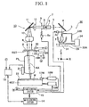
- FIG. 1 shows a projection exposure apparatus (exposure apparatus), which comprises an exposure light source 30 (light source apparatus) ;
- a discharge lamp 1 which comprises an arc discharge type mercury lamp, is fixed to a fixed plate 29 in an insulated state via a mounting apparatus 31 (holding apparatus).
- a cathode and an anode of the discharge lamp 1 are connected to a power supply 34 via flexible electric power cables 33A, 33B, and an elliptical mirror 2 (condenser mirror) is fixed to a bracket (not shown) so that it surrounds a bulb part of the discharge lamp 1.
- a light emitting part inside the bulb part of the discharge lamp 1 is disposed in, for example, the vicinity of a first focal point of the elliptical mirror 2.
- the exposure light source 30 comprises the discharge lamp 1, the elliptical mirror 2, the mounting apparatus 31, the electric power cables 33A, 33B, and the power supply 34 (discussed later in detail).
- a light beam emitted from the discharge lamp 1 is converged in the vicinity of a second focal point by an elliptical mirror 2, after which it passes through the vicinity of a shutter 3, which changes the light beam to divergent light, and then impinges a mirror 4 that folds the optical path.
- the shutter 3 is opened and closed by a shutter drive apparatus 3a.
- the shutter drive apparatus 3a is controlled by a shutter control system not shown in figures.
- a stage control system 15 which is discussed later, controls the shutter drive apparatus 3a based on an instruction from a main control system 14, which provides supervisory control of the operation of the entire apparatus.
- the light beam reflected by the mirror 4 enters an interference filter 5, which selects just exposure light IL that comprises a prescribed bright line (e.g., the i-line, which has a 365 nm wavelength). Furthermore, in addition to the i-line, it is possible to use the g-line, the h-line, light that combines such lines, or, for example, a bright line from a lamp other than a mercury lamp as the exposure light IL.
- the selected exposure light IL enters a fly-eye lens 6 (optical integrator), and numerous secondary light sources are formed on a variable aperture stop 7, which is disposed at the emergent surface of the fly-eye lens 6.
- the exposure light IL that passes through the variable aperture stop 7 then enters a reticle blind (variable field stop) 9 via a first relay lens 8.
- the plane in which the reticle blind 9 is disposed is substantially conjugate with a pattern surface of a reticle R, and an illumination area on the reticle R is defined by setting the shapes of the openings of the reticle blind 9 via a drive apparatus 9a.
- the configuration is such that the stage control system 15 can open and close the reticle blind 9 via the drive apparatus 9a so that a wafer W is not unnecessarily irradiated with exposure light when, for example, the wafer W is stepped.
- the exposure light IL that passes through the reticle blind 9 illuminates a pattern area of the pattern surface of the reticle R via a second relay lens 10, a dichroic mirror 11 that reflects the exposure light IL, and a condenser lens 12.
- the illumination optical system 13 comprises the shutter 3, the mirror 4, the interference filter 5, the fly-eye lens 6, the variable aperture stop 7, the relay lenses 8, 10, the reticle blind 9, the dichroic mirror 11, and the condenser lens 12.
- ⁇ is, for example, 1/4 or 1/5
- the Z axis is parallel to an optical axis AX of the projection optical system PL
- the X axis is parallel to the paper surface of FIG. 1 within a plane that is perpendicular to the Z axis
- the Y axis is perpendicular to the paper surface in FIG. 1 .
- the reticle R is held on a reticle stage RST, which is finely movable in the X and Y directions and in the rotational directions around the Z axis, on a reticle base (not shown).
- the position of the reticle stage RST is measured with high accuracy by a laser interferometer 18R that irradiates a movable mirror 17R, which is fixed to the reticle stage RST, with a measuring laser beam, and that measured value is supplied to the stage control system 15 and the main control system 14.
- the stage control system 15 controls the position of the reticle stage RST via a drive system 19R, which comprises a linear motor, etc.
- the wafer W is held on a wafer stage WST via a wafer holder (not shown), and the wafer stage WST is mounted on a wafer base (not shown) so that it is freely movable in the X and Y directions.
- the position of the wafer stage WST is measured with high accuracy by a laser interferometer 18W that irradiates a movable mirror 17W, which is fixed to the wafer stage WST, with a measuring laser beam, and that measured value is supplied to the stage control system 15 and the main control system 14.
- the stage control system 15 controls the position of the wafer stage WST (wafer W) via a drive system 19W, which comprises a linear motor, etc.
- a step-and-repeat system When exposing the wafer W, a step-and-repeat system repetitively performs: an operation wherein the wafer stage WST moves a shot region of the wafer W into the exposure field of the projection optical system PL; and an operation wherein the reticle R is irradiated with the light beam from the exposure light source 30 via an illumination optical system 13 and the relevant shot region on the wafer W is exposed with the pattern of the reticle R via the projection optical system PL. Thereby, the image of the pattern of the reticle R is transferred to each shot region on the wafer W.
- a reticle alignment microscope 20 that detects the position of an alignment mark formed in the reticle R is installed above the reticle R, and an alignment sensor 21 that detects the position of an alignment mark, which is accessorily provided to each shot region on the wafer W, is installed on a side surface of the projection optical system PL.
- the detection signals of the reticle alignment microscope 20 and the alignment sensor 21 are supplied to an alignment signal processing system 16, which derives the array coordinates of the detected mark by, for example, performing image processing on the detection signals, and this array coordinate information is supplied to the main control system 14.
- the main control system 14 aligns the reticle R and the wafer W based on the array coordinate information.
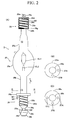
- FIG. 2 (A) is a partial cutaway view that shows the discharge lamp 1 in the exposure light source 30 of FIG. 1 ;
- the discharge lamp 1 comprises: a glass tube 25, which comprises a bulb part 25a and two substantially symmetric cylindrical rod shaped parts 25b, 25c that are fixed so that they sandwich the bulb part 25a; a base part (lamp base or metal base) 26, which is coupled to an end part of the rod shaped part 25b; and a base part 28 that is coupled to an end part of the rod shaped part 25c, the diameter of which decreases toward its outer side in steps.
- a cathode EL2 and an anode EL1 which form the light emitting part in the bulb part 25a, are opposingly fixed and are connected to the base parts 26, 28, respectively; in addition, the base parts 26, 28 are made of a metal that has satisfactory electrical and thermal conductivity.
- the base part 26, the glass tube 25, and the base part 28 are disposed along a straight line that passes through the center of the light emitting part so that the center axes of the rod shaped parts 25b, 25c of the glass tube 25 are links.
- the directions that are parallel to the straight line that links the center axes of the rod shaped parts 25b, 25c are longitudinal direction L of the discharge lamp 1.
- the base parts 26, 28 basically are used as electric power receiving terminals for supplying electric power from the power supply 34 in FIG. 1 to the cathode EL2 and the anode EL1 via the electric power cables 33A, 33B, respectively.
- the base part 26 is also used as a held part so that the glass tube 25 (discharge lamp 1) can be held, and grooves are formed in both base parts 26, 28 wherethrough a gas flows in order to dissipate the heat that is conducted from the glass tube 25.
- an annular flange part 26a contact part
- a columnar shaft part 26b mating part (defining part)), which has an outer diameter that is slightly larger than that of the rod shaped part 25b
- a columnar small diameter part 26k which has an outer diameter that is smaller than that of the shaft part 26b
- a columnar fixed part 26h which has an outer diameter that is slightly smaller than that of the shaft part 26b or that has an external shape that is substantially the same as that of the shaft part 26b;
- a chamfer part 26e is formed at the border between the shaft part 26b and the small diameter part 26k
- a chamfer part 26i is formed on the open end side of the fixed part 26h.
- the columnar shaft part 26b can have a substantially the same diameter as that of the rod shape part 25b.
- the small diameter part 26k is formed by providing a recessed part (stepped part) 26f between the shaft part 26b and the fixed part 26h in the directions that are orthogonal to the longitudinal direction L of the discharge lamp 1.
- the flange part 26a contacts a corresponding member and constitutes a reference for positioning the light emitting part of the glass tube 25 in the longitudinal direction L (first direction); furthermore, the shaft part 26b mates with an opening of the corresponding member and constitutes a reference for positioning the light emitting part in a plane that is orthogonal to the longitudinal direction L.
- a pressed surface 26g is provided on the fixed part 26h by forming the recessed part 26f.
- the pressed surface 26g lies in a plane that is orthogonal to the longitudinal direction L.
- FIG. 2(B) is a cross sectional view of the discharge lamp 1 in FIG. 2(A) taken along the B-B line; as shown in FIG. 2(B) , openings 27A, 27B (positioning parts) are formed at, for example, 90° intervals at two locations in the flange part 26a.
- the discharge lamp 1 is positioned around its axis along the longitudinal direction L by inserting two corresponding pins 70A, 70B (refer to FIG. 4 ) on the side of the mounting apparatus 31 in the openings 27A, 27B. That is, with respect to the mounting apparatus 31, the rotation angle of the discharge lamp 1 around the longitudinal direction L of the discharge lamp 1 is determined.
- openings 27A, 27B there are multiple types of discharge lamps 1 that each have different light emitting power and the like, and therefore the number and/or angle and the like of the openings 27A, 27B differ for each discharge lamp type. Accordingly, there may be one or more openings. Specifically, as shown in FIG. 2 (C) , openings 27A, 27B, 27C are formed at, for example, 90° intervals at three locations in the flange part 26a of a discharge lamp that is of a different type than that of FIG. 2(B) , and three pins are formed in a corresponding mounting apparatus. This reliably prevents the mounting of a discharge lamp of a different specification in the mounting apparatus of the exposure light source of the projection exposure apparatus.
- a helical/spiral groove part 26d is formed around an axis that is parallel to the longitudinal direction L across a portion of an outer surface of the shaft part 26b that extends from the vicinity of the flange part 26a to the chamfer part 26e (recessed part 26f).
- a gas (cooling medium) for cooling the base part 26 flows into the groove part 26d from a ventilating apparatus 71 (refer to FIG. 9 ), which is discussed later, and thereby, even if heat generated by the glass tube 25 is conducted to the base part 26, the base part 26 can be efficiently cooled, and the glass tube 25 is also cooled as a result.
- the positional relationship between the groove part 26d and the openings 27A, 27B in FIG. 2(B) is set so that the cooled gas is efficiently supplied from the ventilating apparatus 71 (refer to FIG. 9 ) to the groove part 26d in a state wherein the corresponding pins of the mounting apparatus 31 in FIG. 1 are inserted in the openings 27A, 27B.
- the recessed part 26f is formed in the base part 26 on the cathode EL2 side between the shaft part 26b and the fixed part 26h. Namely, because the small diameter part 26k, which has a cross sectional area in a plane that is orthogonal to the longitudinal direction L that is smaller than that of the shaft part 26b, is provided between the shaft part 26b and the fixed part 26h, part of the urging mechanism of the mounting apparatus 31 in FIG. 1 can be easily inserted therein.
- the shaft part 26b and the small diameter part 26k each have a circular cross section centered on an axis that is parallel to the longitudinal directions L, and the diameter of the circular cross section of the small diameter part 26k is preferably less than half (e.g., approximately 1/3) that of the shaft part 26b.
- the groove part 26d is in fluid communication with the recessed part 26f through the chamfer part 26e, the cooling gas can flow smoothly in the longitudinal direction L.
- the groove part 26d is helically formed in the surface of the shaft part 26b, and consequently that cooling gas can efficiently cool the entire shaft part 26b (base part 26).
- a plurality of groove parts may be provided to the surface of the shaft part 26b in a straight line substantially along the longitudinal directions L, and the cooling gas may flow in these groove parts, as described later.
- LT1 is the length of the entire discharge lamp 1 in the longitudinal direction L, including the glass tube 25 and the base parts 26, 28, and LT2 is the length of the base part 26, which is held by the mounting apparatus 31, in the longitudinal direction L
- the length LT2 is preferable for the length LT2 to be greater than or equal to 1/5 and less than 1/4 of the length LT1 (for example, approximately 0.22 times LT1), as shown
- a length LT3 of the base part 28 in the longitudinal direction L on another free end side is, for example, greater than or equal to 1/8 and less than 1/5 of the length LT1 (for example, approximately 0.15 times the length LT1).
- the surface area of the portion of the surface of the shaft part 26b of the base part 26 that mates with (contacts) the opening of the corresponding member of the mounting apparatus 31 in FIG. 1 is preferably greater than the surface area of the groove part 26d formed in the shaft part 26b.
- a width M1 of the surface (protruding part) of the shaft part 26b in the longitudinal direction L in FIG. 2 (A) is greater than a width M2 of the groove part 26d, as described below.
- the surface area of the portion of the surface of the shaft part 26b that mates with the opening of the corresponding member is preferably at least two times (for example, approximately three times) that of the groove part 26d. This means that the equation below holds true. Thereby, the holding force applied to the shaft part 26b is further increased and a comparatively greater cooling effect is obtained.
- the base part 28 connected to the anode EL1 of FIG. 2(A) has, in sequence from the rod shaped part 25c side to the open end side: a thin annular part 28h, which has an outer diameter that is slightly larger than the maximum outer diameter of the rod shaped part 25c; a columnar shaft part 28c, which has an outer diameter that is substantially the same as that of the annular part 28h or has an outer diameter that is smaller than that of the annular parts 28h; and a cylindrical cover part 28b, which covers the surface of the shaft part 28c on the open end side, spaced apart therefrom by a small space 28d and which and mates with the shaft part 28c.
- a cylindrical terminal part 28a which has an outer diameter that is approximately 1/3 that of the shaft part 28c, is provided on the cylindrical cover part 28b. Furthermore, a groove part 28f is formed helically around an axis that is parallel to the longitudinal direction L in the surface of the shaft part 28c, extending from the open end side to the annular parts 28h. A recessed part 28g is provided between the annular part 28h and the shaft part 28c, and the groove part 28f of the shaft part 28c is in fluid communication with the recessed part 28g. In addition, a circulation hole 28e is formed in the terminal part 28a.
- the circulation hole fluidcally connects the outer part of the terminal part 28a and the inside part of the cover part 28b, which is a space 28d, so that they are in fluid communication with each other.
- the cylindrical cover part 28b is formed from a metal that has satisfactory electrical and thermal conductivity.
- the electric power cable 33B shown in FIG. 8 is connected to the terminal part 28a of the base part 28.
- piping for supplying cooled gas (cooling medium) through the circulation hole 28e to the groove part 28f are housed in the electric power cable 33B.
- the electric power cable 33B is used for supplying cooled gas in addition to electric power, and therefore can also be called a service cable, and the terminal part 28a can also be called a service receiving terminal. Because the electric power cable 33B and the terminal part 28a are used to receive (supply) electric power and cooled gas, respectively, they can be formed compactly.
- the cooling gas that is supplied from the electric power cable 33B to the circulation hole 28e inside the terminal part 28a flows inside a conduit that is formed between the cover part 28b and the groove part 28f on the surface of the shaft part 28c of the base part 28, and then is exhausted from the recessed part 28g to the outer side.
- the entire base part 28 can be efficiently cooled because the groove part 28f (conduit) is helical.
- multiple groove parts each of which is provided substantially parallel to the longitudinal direction L, may be formed in the surface of the shaft part 28c in the base part 28, and the cooling gas may be supplied to these groove parts.
- the conduit through which the cooling gas flows may not necessarily be formed in the base part 28 for the anode EL1.
- the electrode that is connected to the base part 26 held by the mounting apparatus 31 it is also possible for the electrode that is connected to the base part 28 held by the mounting apparatus 31 to serve as the anode, and for the electrode that is connected to the base part 28 on the free end side to serve as the cathode.
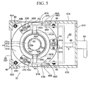
- FIG. 3 shows the configuration of the mounting apparatus 31 of the exposure light source 30 in FIG. 1
- FIG. 4 is a plan view of the mounting apparatus 31 in FIG. 3
- FIG. 5 is a cross sectional view taken along the A-A line in FIG. 3
- FIG. 6 is a cross sectional view taken along the B-B line in FIG. 3
- a thin, flat, plate shaped bottom plate 36 is fixed to a surface of a substantially square, flat, plate shaped ceramic insulating plate 32 with bolts 35 at a plurality of locations.
- columnar guide members 37A, 37B, 37C (refer to FIG.
- Recessed parts 32a which each house one of the bolts 39A, are formed in the front surface of the insulating plate 32, which makes it possible to fix the bottom plate 36 to the front surface of the insulating plate 32 so that they are in close contact.
- an opening 36a is formed for passing one of the bolts 40 therethrough, and the insulating plate 32 is fixed to the fixed plate 29 by passing the bolts 40 (refer to FIG. 5 ) through the openings 36a at those four locations.
- the mounting apparatus 31 is fixed to the fixed plate 29 in an insulated state.
- frames 46A, 46B which are L-shaped in a cross sectional view, are fixed to the bottom plate 36 at the two left side corners, flat, plate shaped panel plates 47A, 47B are fixed to the bottom plate 36 at the two right side corners so that they project rightward, and the right end parts of the panel plates 47A, 47B are coupled by a flat, plate shaped panel plate 47C.
- an upper plate 45 which is substantially square, flat plate shaped and has a large circular opening 45a (refer to FIG. 3 ) formed at its center, is fixed on the frames 46A, 46B and the panel plates 47A, 47B.
- Three small openings are also formed in the upper plate 45 for passing the tip parts of the three guide members 37A-37C therethrough.
- an annular positioning plate 50 is fixed to an upper surface of the upper plate 45 by bolts 51 so that it covers the opening 45a, and a flange part of a cylindrical member 52, which is substantially cylindrical, is fixed to a bottom surface of the positioning plate 50 by bolts 53 at, for example, four locations.
- the flange part 26a of the base part 26 of the discharge lamp 1 in FIG. 2 (A) is mounted to an upper surface 50a of the positioning plate 50, and the shaft part 26b of the base part 26 is mated to a circular opening 50b at the center of the positioning plate 50 and to an inner surface of the cylindrical member 52, which is continuous therewith.
- the positioning plate 50 and the cylindrical member 52 constitute a member that integrally holds the base part 26 of the discharge lamp 1.
- the directions along the center axis of the cylindrical member 52 are called movement directions D of the discharge lamp 1.
- a vent 50c is formed so that its side surface and the opening 50b of the positioning plate 50 are in communication, and a terminal of a highly flexible piping 73 is connected to the vent 50c in order to supply the cooled gas from the ventilating apparatus 71 in FIG. 9 .
- the pins 70A, 70B are fixed to the upper surface 50a of the positioning plate 50 in an arrangement that corresponds to that of the openings 27A, 27B of the flange part 26a of the discharge lamp 1 in FIG. 2(B) . Thereby, the flange part 26a of the discharge lamp 1 can always be mounted on the positioning plate 50 at the same angular position.
- the positioning plate 50, the upper plate 45, and the frames 46A, 46B have electrical continuity and are formed from a metal that has satisfactory electrical and thermal conductivity so as to increase the heat radiating effect, and the electric power cable 33A is fixed to the frame 46A via a bolt 55.
- the discharge lamp 1 By holding the discharge lamp 1 so that the flange part 26a of the base part 26 in FIG. 2 (A) contacts the positioning plate 50, electric power is supplied to the base part 26 via the electric power cable 33A, the frame 46A, the upper plate 45, and the positioning plate 50.
- the cylindrical member 52 is made of a metal that has satisfactory thermal conductivity.
- the positioning plate 50 (coupled with the cylindrical member 52) on the upper plate 45, it is disposed in a state wherein a moving member 41, which is cupped and has an opening at its center so that it can surround the cylindrical member 52, can move in the movement directions D.
- the moving member 41 is formed, in sequence from the upper plate 45 side to the bottom plate 36 side, by the coupling of: an annular part 41a, which is disposed proximate to the cylindrical member 52; a conical inclined part 41b wherein its inner surface (tapered surface) widens by substantially 5° as one goes toward the bottom plate 36 in the movement directions D; a conical housing part 41c, the inner surface(tapered surface) of which widens more than the inclined part 41b by approximately 40°; and a drive part 41d, which has an annular shape that is larger than the annular part 41a, wherein openings are formed at three locations for passing the guide members 37A-37C (refer to FIG. 5 ) therethrough.
- small, flat, plate shaped lifting members 48A, 48B are fixed at two locations to an upper end of the annular part 41a so that they sandwich such in a manner wherein they are substantially parallel to the panel plates 47A, 47B.
- coupling members 42A, 42B, 42C are fixed to the drive part 41d of the moving member 41 by bolts 43 so that they cover three openings that are provided at equiangular intervals, and the guide members 37A-37C are inserted through the through holes of the coupling members 42A-42C, respectively.
- substantially inverse U-shaped fasteners 38A, 38B, 38C are fixed to the upper surface of the upper plate 45 using bolts 39C so that they cover the three holes that are disposed so that they surround the positioning plate 50, and the tips of the guide members 37A-37C in FIG. 5 are fixed to the centers of the fasteners 38A-38C, respectively, using bolts 39B.
- compression coil springs 44A, 44B, 44C (refer to FIG. 5 ) are mounted between the fasteners 38A-38C and the coupling members 42A-42C so that they cover the guide members 37A-37C, respectively.
- the compression coil springs 44A-44C continuously apply a pressing force F1 to the drive part 41d of the moving member 41 in the movement direction D that goes toward the bottom plate 36 side via the three coupling members 42A-42C. Accordingly, the moving member 41 moves along the cylindrical member 52 toward the bottom plate 36 side unless a switching link mechanism 63 (discussed later) applies a driving force to the lifting members 48A, 48B, which are fixed to the annular part 41a of the moving member 41, toward the upper plate 45 side.
- three rectangular window parts 52a, 52b, 52c are formed (at the same angles as the guide members 37A-37C) at substantially intermediate positions of the side surface of the cylindrical member 52 between the upper plate 45 and the bottom plate 36, three protruding parts 52d, 52e, 52f are formed at the same angles as the window parts 52a-52c on a lower end part of the cylindrical member 52, and substantially L-shaped fixing arms 55A, 55B, 55C (refer to FIG. 6 ) are fixed to the protruding parts 52d-52f, respectively, so that they are rotatable around corresponding shafts 56.
- a coil spring 62A a small torque is continuously applied to each of the fixing arms 55A-55C so that it rotates toward the outer side with respect to the cylindrical member 52.
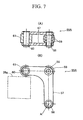
- FIG. 7(A) is a plan cross sectional view of the fixing arm 55A in FIG. 3
- FIG. 7(B) is a front view of that fixing arm 55A
- one end of a frame 57 that constitutes the fixing arm 55A is rotatable around a center of rotation A via the corresponding shaft 56
- a roller 61 is fixed to another end of the frame 57 via a rotary shaft 60
- rollers 59 are each fixed to an intermediate bent part of the frame 57 via a small bearing 58.
- each of the rollers 59, 61 is rotatable, and the counterclockwise rotation of the fixing arm 55A around the shaft 56 urges the roller 61 toward a surface that is to be fixed (in the present example, the pressed surface 26g of the base part 26 of the discharge lamp 1 in FIG. 2(A) ).
- the moving member 41 is at the position along the cylindrical member 52 that is closest to the upper plate 45, the rollers 59 at the bent parts of the fixing arms 55A-55C are urged toward the housing part 41c of the moving member 41, and the rollers 61 emerge from the window parts 52a-52c of the cylindrical member 52. Accordingly, the shaft part 26b and the fixed part 26h of the base part 26 of the discharge lamp 1 in FIG. 2 (A) can move freely in the movement directions D along the opening 50b of the positioning plate 50 and the inner surface of the cylindrical member 52.
- FIG. 9 shows one example of a state wherein the moving member 41 has been lowered from the state in FIG. 3 to the position along the cylindrical member 52 that is closest to the bottom plate 36; in FIG. 9 , the roller 59 of the fixing arm 55A (and likewise for those of the other fixing arms 55B, 55C) contacts the inclined part 41b of the moving member 41 and is urged toward the inner side of the cylindrical member 52. As a result, torque is applied counterclockwise around the shaft 56 to the fixing arm 55A, and the roller 61 on the other end side of the fixing arm 55A is inserted inwardly through the window part 52a of the cylindrical member 52. In the state in FIG.
- the shaft part 26b the fixed part 26h of the base part 26 of the discharge lamp 1 mate inside the cylindrical member 52, and consequently the roller 61 of the fixing arm 55A is inserted into the recessed part 26f of the base part 26 and, furthermore, contacts the pressed surface 26g, which is the upper surface of the fixed part 26h.
- the pressing force of the compression coil springs 44A, 44B and the like is applied to the pressed surface 26g (base part 26) via the moving member 41 and the fixing arm 55A, and consequently the flange part 26a of the base part 26 is pushed against the upper surface 50a of the positioning plate 50 of the mounting apparatus 31, which stably holds the base part 26 along with the discharge lamp 1.
- the fixing arms 55A-55C constitute part of the member that applies a pressing force to the base part 26 (fixed part 26h) toward the bottom plate 36 side.
- the following explains the configuration of the switching link mechanism 63, which lifts the lifting members 48A, 48B of the moving member 41 to the upper plate 45 side in order to release the pressing force that is applied to the base part 26 (fixed part 26h) by the fixing arm 55A-55C.
- a rotary lever part 64 which comprises an insulating material, is fixed to substantially the center of the panel plate 47C, a movable rod 65, which is movable in drive directions E that are orthogonal to the movement directions D, is coupled to a tip of the rotary lever part 64 on the inner side of the panel plate 47C, and a branching member 66, which is substantially U-shaped in a plan view, is fixed to a tip of the movable rod 65.
- the operator's manual rotation of the rotary lever part 64 causes the movable rod 65, which is interlocked therewith, to move in the drive directions E.
- the mechanism that moves the movable rod 65 is arbitrary and, for example, the operator may directly manipulate an extended movable rod 65 without using the rotary lever part 64.
- the drive directions E may be, for example, substantially parallel to the movement directions D.
- the panel plates 47A-47C that hold the rotary lever part 64 are both formed from, for example, an insulating material. Furthermore, one end each of two long, thin link members 67A, 67B, which are rotatable around shafts 66A, 66B, respectively, are coupled to two tip parts of the branching member 66; rollers 69A, 69B are rotatably coupled to the other ends of the link members 67A, 67B; and the rollers 69A, 69B are capable of contacting the lifting members 48A, 48B, which are fixed to the annular part 41a of the upper end of the moving member 41, from the bottom surface.
- the switching link mechanism 63 comprises the rotary lever part 64, the movable rod 65, the branching member 66, the link members 67A, 67B, the link members 68A, 68B, and the rollers 69A, 69B.
- each of the intermediate positions is not limited to the right middle position, and can be any position between one end part of the link member 68A or 68B and another end part.
- the two end parts 147A, 148B, which are surrounded by dotted lines, of the housing part 41c and the drive part 41d of the moving member 41 may be eliminated, as shown in FIG. 5 .
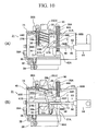
- FIG. 10 corresponds to views that show the link members 67B, 68B on the near side of the switching link mechanism 63 in FIG. 3 as well as a state wherein the base part 26 of the discharge lamp 1 is held by the mounting apparatus 31; as shown in FIG. 10(A) , in a state wherein the rotary lever part 64 has been operated and the movable rod 65 has moved to its right end part in the drive direction E thereof, the link member 67B (likewise, the link member 67A in FIG. 5 ) is substantially parallel to the movable rod 65, and the moving member 41 descends to the lowest end in the movement direction D thereof.
- the roller 61 of the fixing arm 55A in FIG. 3 urges the fixed part 26h of the base part 26 downward, and the base part 26 is thereby held stably.
- the fixing arm 55A rotates to the outer side until it contacts the housing part 41c, by the coil spring 62A, the roller 61 emerges from the window part 52a of the cylindrical member 52, and consequently the fixed part 26h of the base part 26 can be pulled out from the cylindrical member 52, and the discharge lamp 1 can be removed from the mounting apparatus 31 thereby.
- the switching link mechanism 63 in FIG. 5 makes it possible to switch easily between fixing and releasing the base part 26 of the discharge lamp 1 to and from the mounting apparatus 31. Furthermore, in addition to the switching link mechanism 63, it is possible to use an arbitrary mechanism that lifts the moving member 41 in FIG. 3 in one of the movement directions D. For example, it is also possible to use a mechanism wherein the rollers 69A, 69B are directly fixed to the tip parts of the link members 68A, 68B in FIG. 5 , and the lifting members 48A, 48B of the moving member 41 are raised by the operator's rotation of the link members 68A, 68B.
- the mounting apparatus 31 comprises: the frame mechanism, which comprises the insulating plate 32, the bottom plate 36, the upper plate 45, the frames 46A, 46B, and the panel plates 47A-47C; the member that comprises the positioning plate 50 and the cylindrical member 52 and that holds the base part 26 of the discharge lamp 1; the fixing arms 55A-55C, which apply the pressing force to the fixed part 26h of the base part 26; the mechanism that comprises the moving member 41, the guide members 37A-37C, the coupling members 42A-42C, the coil spring 62A, as well as the compression coil springs 44A-44C (elastic members), and that applies the urging force to the fixing arms 55A-55C; the switching link mechanism 63, which releases the urging force applied to the fixing arms 55A-55C by the previously mentioned mechanism; the electric power cable 33B on the base part 28 side in FIG. 8 ; a gas supply apparatus (not shown) that supplies cooled gas to the electric power
- the ventilating apparatus 71 comprises: a filter part 71a, which eliminates dust from the gas (e.g., air) that was taken in from an intake port 72; a cooling part 71b that cools the gas supplied from the filter part 71a; and a ventilating part 71c that supplies a prescribed volume of flow of the gas, which is supplied from the cooling part 71b, to the piping 73 side.
- a temperature sensor may be provided to the outer surface of the cylindrical member 52, and the set temperature in the cooling part 71b may be controlled based on the measurement result of the temperature sensor.
- FIG. 8 shows a state wherein the discharge lamp 1 is mounted to the mounting apparatus 31
- FIG. 9 is an enlarged view that shows the base part 26 of the discharge lamp 1 in FIG. 8 and the mounting apparatus 31
- FIG. 10(A)-(B) which corresponds to FIG. 3 , show the operation of the switching link mechanism 63.
- the roller 61 of the fixing arm 55A is inserted through the window part 52a of the cylindrical member 52 toward the recessed part 26f side of the base part 26; furthermore, the roller 61 urges the pressed surface 26g of the base part 26 toward the bottom plate 36 side.
- the movement directions D of the base part 26 along the inner surface of the cylindrical member 52 coincide with the longitudinal direction of the discharge lamp 1.
- the discharge lamp 1 is stably held by the mounting apparatus 31 in the state wherein: the flange part 26a of the base part 26 tightly contacts the upper surface 50a of the positioning plate 50; and the shaft part 26b of the base part 26 is mated to the opening 50b of the positioning plate 50 and the inner surface of the cylindrical member 52.
- the highly flexible electric power cable 33B is coupled to the terminal part 28a of the base part 28. Electric power is supplied from the electric power cable 33B to the terminal part 28a, and cooled gas is supplied via the piping inside the electric power cable 33B to the conduit between the groove part 28f and the cover part 28b of the base part 28. The supplied gas is exhausted from the recessed part 28g, which is provided between the shaft part 28c and thee annular part 28h, to the outer side, and thereby the base part 28 is efficiently cooled.
- FIG. 9 which is an enlargement of the principal parts in FIG. 8
- cooled gas is supplied from the ventilating apparatus 71 to the vent 50c of the positioning plate 50 via the piping 73.
- the supplied gas is exhausted out of the window part 52a (and the other two window parts) of the cylindrical member 52 via the vent 50c, the conduit between the cylindrical member 52 and the groove part 26d of the base part 26, and the recessed part 26f.
- the exposure light source 30 of the present example which comprises the discharge lamp 1 and the mounting apparatus 31, it is possible to easily remove and mount the discharge lamp 1 from and to the mounting apparatus 31 in a short period of time merely by the switching link mechanism 63 releasing the pressing applied by the fixing arms 55A-55C to the fixed part 26h of the base part 26 of the discharge lamp 1.
- the discharge lamp 1 is pressed and fixed to the positioning plate 50 with a prescribed and substantially constant pressing force due to the urging force of the compression coil springs 44A-44C merely by the switching link mechanism 63 commencing the pressing by the fixing arms 55A-55C against the fixed part 26h in one of the movement directions D (equal to the longitudinal direction L of the discharge lamp 1) of the base part 26. Accordingly, the pressing force that is applied when fixing the discharge lamp 1 to the mounting apparatus 31 can be set easily within a target range by adjusting, for example, the spring constants of those compression coil springs 44A-44C.
- the mounting apparatus 31 comprises: the moving member 41, which comprises the inclined part 41b that has an inner surface (tapered surface) that is inclined with respect to the movement directions D, that moves in the movement directions D by the action of the elastic force of the compression coil springs 44A-44C; and the fixing arms 55A-55C, which contact the inner surface of the inclined part 41b and convert the movement of the moving member 41 in one of the movement directions D to movement toward the recessed part 26f of the base part 26, wherein the rollers 61 at their tips are inserted into the recessed part 26f, in the insertion direction; thereby, the fixing arm 55A urges the pressed surface 26g, which makes it possible to apply the pressing force to the base part 26 in one of the movement directions D easily.
- the fixing arm 55A urges the pressed surface 26g, which makes it possible to apply the pressing force to the base part 26 in one of the movement directions D easily.
- the compression coil springs 44A-44C it is also possible to use tension coil springs, leaf springs, or the like as the members that apply the pressing force F1 to the moving member 41.
- the fixing arms 55A-55C is disposed at the circumference of the base part 26 at equiangular intervals, the base part 26 is held by the mounting apparatus 31 with a uniform force.
- the cable for supplying electric power and the piping through which the cooled gas is supplied are housed in parallel in the electric power cable 33B on the base part 28 side .
- a flexible tubular cable that is formed from a conductive body that conducts the electric power and guides the cooling gas may be used as the electric power cable 33B. Thereby, it is possible to simplify the configuration of the electric power cable 33B.
- One example of the manufacturing method is a method of manufacturing a projection exposure apparatus wherein light generated by a discharge between two electrodes of the discharge lamp 1 in FIG. 1 is used to expose the wafer W with the image of the pattern of the reticle R, and comprises the steps of: a step S1 (not shown) that mounts the discharge lamp 1 to the mounting apparatus 31 shown in FIG. 8 , which is for holding the discharge lamp 1, via the base part 26 of the discharge lamp 1; a step S2 (not shown) that connects the electric power cable 33B (service cable) to the terminal part 28a of the base part 28 of the discharge lamp 1; and a step S3 (not shown) that cools the base part 26 of the discharge lamp 1 in a state wherein the discharge lamp 1 is thus mounted to the mounting apparatus 31. Thereby, the discharge lamp 1 can be efficiently cooled.
- step S1 can further include: a step S11 (not shown) that inserts part (the shaft part 26b and the fixed part 26h) of the base part 26 in the opening 50b of the positioning plate 50 and along the inner surface of the cylindrical member 52 of the mounting apparatus 31; a step S12 (not shown) wherein the base part 26, which is inserted in the mounting apparatus 31, is urged with a pressing force (holding force) so that the discharge lamp 1 can be held; and a step S13 (not shown) that forms a cooling gas conduit between the cylindrical member 52 of the mounting apparatus 31 and the groove part 26d of the base part 26.
- step S3 can include a step 31 (not shown) that supplies cooling gas from the ventilating apparatus 71 in FIG. 9 to the conduit formed by step S13.
- step 31 (not shown) that supplies cooling gas from the ventilating apparatus 71 in FIG. 9 to the conduit formed by step S13.
- step S4 that cools the base part 28, to which the electric power cable 33B is connected, with the cooling liquid supplied via the electric power cable 33B.
- the base part 28 is cooled and, in turn, it is also possible to cool the glass tube 25 of the discharge lamp 1 efficiently.
- the cooling medium (gas or liquid) flows to the conduit that is formed between the groove part of the surface (or the surface itself) of a shaft part of the one base part and the cylindrical member 52 of the mounting apparatus 31 in FIG. 3 ; for each discharge lamp of discharge lamps 1P, 1Q shown in FIG. 15 (C) and (D) , the cooling medium flows to a fluid path, which is provided between a fixed part (urged part) and the vicinity of the flange part so that it passes through the interior of the shaft part of the one base part; and for each discharge lamp of discharge lamps 1AA, 1AB shown in FIG.
- FIGS. 11-18 that correspond to those in FIG. 2(A)-(B) are assigned identical or similar symbols, and detailed explanations thereof are omitted or simplified.
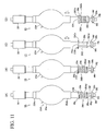
- the discharge lamp 1A in FIG. 11(A) is configured by fixing base parts 26A, 28, whereto a cathode and an anode (not shown) for forming the light emitting part are respectively connected, so that a glass tube 25A, which includes the bulb part 25a wherein the light emitting part is formed, is interposed thereby in the longitudinal direction, and the base part 26A is fixed by the mounting apparatus 31 in FIG. 3(A). Furthermore, although the stepped shapes of rod shaped parts 25Ab, 25Ac of that glass tube 25A are slightly different from those of the rod shaped parts 25b, 25c of the glass tube 25 of the discharge lamp 1 in FIG. 2(A) , the wavelength and the output of emitted illumination light are substantially the same.
- the base part 26A of the discharge lamp 1A in FIG. 11 (A) differs from the base part 26 in FIG. 2(A) in that: a groove part 26Ad, which is formed in the shaft part 26b (mating part) thereof is formed helically (e.g., in the shape of a groove for a screw) in a circumferential direction that is the reverse of that of the groove part 26d of the base part 26 in FIG. 2 (A) ; and a tip part 26j that is columnar in a cross sectional view and that is substantially the same as the recessed part 26f is formed at the tip of that shaft part 26b.
- a groove part 26Ad which is formed in the shaft part 26b (mating part) thereof is formed helically (e.g., in the shape of a groove for a screw) in a circumferential direction that is the reverse of that of the groove part 26d of the base part 26 in FIG. 2 (A)
- a tip part 26j that is columnar in a cross section
- the positional relationship between the opening 27B and a starting point of the groove part 26Ad on the flange part 26a (contact part) side is set so that, when the base part 26A is mounted to the mounting apparatus 31 in FIG. 3 , cooled gas (cooling medium), which is supplied from the ventilating apparatus 71 in FIG. 9 to the vent 50c of the positioning plate 50 in FIG. 3 , flows into the groove part 26Ad at the starting point. Thereby, the base part 26A and, in turn, the discharge lamp 1A are efficiently cooled.
- cooled gas cooling medium
- the discharge lamp 1B in FIG. 11 (B) differs from the discharge lamp 1A in FIG. 11 (A) in that: it is configured so that the glass tube 25A is interposed by base parts 26B, 28; a ring shaped cutaway part 26c (groove part) is formed in the vicinity of the flange part 26a of the shaft part 26b of the base part 26B; and the groove part 26Ad communicates with this cutaway part 26c.
- cooled gas which is supplied from the ventilating apparatus 71 in FIG. 9 to the vent 50c of the positioning plate 50 in FIG. 3 , flows into the groove part 26Ad via the cutaway part 26c. This makes it easier to fabricate the groove part 26Ad.
- the discharge lamp 1C in FIG. 11 (C) differs from the discharge lamp 1A in FIG. 11 (A) in that: a ring shaped cutaway part 26Cc is formed in the vicinity of the flange part 26a of the shaft part 26b of a base part 26C thereof; and multiple groove parts 26Cd, which are parallel to the longitudinal direction L of the glass tube 25A, are formed in the surface of the shaft part 26b so that the cutaway part 26Cc and the recessed part 26f (stepped part) are in fluid communication.
- cooled gas which is supplied from the ventilating apparatus 71 in FIG. 9 to the vent 50c of the positioning plate 50 in FIG. 3 , flows to the recessed part 26f side via the cutaway part 26Cc and the groove parts 26Cd.
- the discharge lamp 1C is efficiently cooled.
- the discharge lamp 1D in FIG. 11 (D) differs from the discharge lamp 1A in FIG. 11 (A) in that: a groove part D1 is provided to a flange part 26Da of the base part 26D thereof; multiple ring shaped cutaway parts 26Dk, which are centered on an axis that is parallel to the longitudinal direction L, are formed in the longitudinal direction L in the surface of the shaft part 26b; and multiple groove parts D2 are formed in the shaft part 26b between these cutaway parts 26Dk at intervals of, for example, 180°.
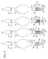
- the discharge lamp 1E in FIG. 12 (A) differs from the discharge lamp 1A in FIG. 11 (A) in that: multiple ring shaped cutaway parts 26Ek (lateral grooves), which are centered on an axis that is parallel to the longitudinal direction L, are formed in the longitudinal direction L in the surface of the shaft part 26b of a base part 26E; and the portions of the shaft part 26b that are between these cutaway parts 26Ek act as a plurality of heat radiating fins.
- the base part 26E of the discharge lamp 1E is mounted to the mounting apparatus 31 in FIG. 3
- the cooled gas which is supplied from the ventilating apparatus 71 in FIG. 9 to the vent 50c of the positioning plate 50 in FIG. 3 , flows over the surface of the shaft part 26b via the cutaway parts 26Ek, and thereby the discharge lamp 1E is efficiently cooled.
- the discharg lamp according to Fig. 12 (A) does not form past of the present invention.
- the discharge lamp 1F in FIG. 12 (B) differs from the discharge lamp 1A in FIG. 11(A) in that: multiple ring shaped cutaway parts 26Fk, which are centered on an axis that is parallel to the longitudinal direction L, are formed in the longitudinal direction L in the surface of the shaft part 26b of a base part 26F; and four groove parts G1, G2, G3 (the fourth groove part is not shown) are formed in the shaft part 26b between the cutaway parts 26Fk at 90° intervals.
- the base part 26F of the discharge lamp 1F is mounted to the mounting apparatus 31 in FIG. 3
- the cooled gas which is supplied from the ventilating apparatus 71 in FIG. 9 to the vent 50c of the positioning plate 50 in FIG. 3 , flows over the surface of the shaft part 26b via the cutaway parts 26Fk and the groove part F11 to the recessed part 26f side, and thereby the discharge lamp 1F is efficiently cooled.
- the discharge lamp 1G in FIG. 12 (C) differs from the discharge lamp 1B in FIG. 11 (B) in that the cutaway part 26c is formed in the vicinity of the flange part 26a of the shaft part 26b of a base part 26G thereof, and two helical groove parts 26d, 26Gd, which differ from one another in their rotational directions, are formed in the surface of the shaft part 26b so that they intersect and communicate with the cutaway part 26c.
- the discharge lamp 1H in FIG. 12(D) differs from the discharge lamp 1B in FIG. 11 (B) in that the cutaway part 26c is formed in the vicinity of the flange part 26a of the shaft part 26b of a base part 26H thereof, and multiple helical, parallel groove parts 26Hd are formed as a multi-threaded screw (a double-threaded screw in the present embodiment) in the surface of the shaft part 26b so that they communicate with the cutaway part 26c.
- This discharge lamp 1G (or 1H) exhibits particularly excellent cooling effects because the cooled gas flows along the two groove parts 26d, 26Gd (or the groove parts 26Hd).
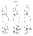
- the discharge lamp 11 in FIG. 13 (A) differs from the discharge lamp 1A in FIG. 11 (A) in that: a pressed surface 26Ig of the portions at the tip part of the shaft part 26b of a base part 26I thereof that are urged by, for example, the fixing arm 55A in FIG. 3 is gradually inclined with respect to a plane that is perpendicular to the longitudinal direction of the glass tube 25A; and a chamfer part 26Ii that, along with the pressed surface 26Ig, sandwiches the fixed part 26h is gradually inclined substantially symmetric to the pressed surface 26Ig.
- the base part 26I of the discharge lamp 1I is mounted to the mounting apparatus 31 in FIG. 3 , it is possible to increase the urging force that is applied to the pressed surface 26Ig by, for example, the fixing arm 55A. In this case, the discharge lamp 1I can be held more stably.
- the discharge lamp 1J in FIG. 13 (B) differs from the discharge lamp 1A in FIG. 11 (A) in that: a pressed surface 26Jg of a base part 26J thereof is inclined in a direction that is the reverse of that of the pressed surface 26Ig in FIG. 13 (A) ; and the fixed part 26h is bowl shaped.
- the supporting method of the fixing arm 55A and the like in FIG. 3 there are cases wherein, when the base part 26J of the discharge lamp 1J is mounted to the mounting apparatus 31 in FIG. 3 , it is possible to increase the urging force that is applied to the pressed surface 26Jg by, for example, the fixing arm 55A. In this case as well, the discharge lamp 1J can be held more stably.
- the discharge lamp 1K in FIG. 13(C) differs from the discharge lamp 1A in FIG. 11(A) in that a fixed part 26Kh of a base part 26K thereof is small. Thereby, there are cases wherein the configuration of the mounting apparatus 31 in FIG. 3 can be reduced in size.
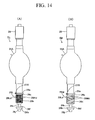
- the discharge lamp 1L in FIG. 14 (A) differs from the discharge lamp 1B in FIG. 11 (B) in that the cutaway part 26c is formed in the vicinity of the flange part 26a of the shaft part 26b of a base part 26L thereof, and multiple helical groove parts 26Ld, 26Hd, which have different rotational directions, are formed as two multi-threaded screws (e.g., double-threaded screw) in the surface of the shaft part 26b so that they intersect and communicate with the cutaway part 26c.
- the cutaway part 26c is formed in the vicinity of the flange part 26a of the shaft part 26b of a base part 26L thereof, and multiple helical groove parts 26Ld, 26Hd, which have different rotational directions, are formed as two multi-threaded screws (e.g., double-threaded screw) in the surface of the shaft part 26b so that they intersect and communicate with the cutaway part 26c.
- the discharge lamp 1M in FIG. 14 (B) differs from the discharge lamp 1B in FIG. 11(B) in that a cutaway part 26c is formed in the vicinity of the flange part 26a of the shaft part 26b of a base part 26M thereof; in addition, multiple helical, parallel groove parts 26Ld and multiple long pitched, helical, parallel groove parts 26Md are formed as multi-threaded screws (e.g., a double-threaded screw and a triple-threaded screw, respectively) in the surface of the shaft part 26b so that they intersect and communicate with the cutaway part 26c.
- These discharge lamps 1L, 1M exhibit particularly excellent cooling effects because they include the groove parts through which the cooling medium flows.
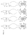
- the discharge lamp 1N in FIG. 15 (A) differs from the discharge lamp 1B in FIG. 11 (B) in that three fixed parts 26h1, 26h2, 26h3 are provided in the portion at the tip part of the shaft part 26b of a base part 26N thereof that is urged by the fixing arm 55A and the like in FIG. 3 . Because the three fixing arms 55A-55C in FIG. 6 urge the fixed parts 26h1-26h3, respectively, in the longitudinal direction when the base part 26N of the discharge lamp 1N is mounted to the mounting apparatus 31 in FIG. 3 , the discharge lamp 1N can be held more stably by the mounting apparatus 31. In this case, the base part 26N can be made lighter than, for example, the discharge lamp 1B in FIG. 11(B) .
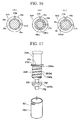
- the discharge lamp 10 in FIG. 15 (B) differs from the discharge lamp 1A in FIG. 11(A) in that, with the exception of numerous rectangular shaped protruding parts 26n, the surface of the shaft part 26b of a base part 260 thereof is a recessed part 26m.
- FIG. 16 (A) which is a cross sectional view taken along the A-A line in FIG. 16(B) , groove parts are formed between the protruding parts 26n of the shaft part 26b of the base part 260.
- the circulation resistance can be reduced by reducing the number of protruding parts 26n, which is more suited to a situation in which it is desired to increase the flow volume of the gas to be supplied.
- the discharge lamp 1P in FIG. 15(C) differs from the discharge lamp 1B in FIG. 11(B) in that a ring shaped cutaway part 26Pc (groove part) is formed in the vicinity of the flange part 26a (in the present embodiment, at the position at which it contacts the flange part 26a) of the shaft part 26b of a base part 26P thereof, and multiple fluid paths 26Pd, each of which comprises a through hole that is parallel to the longitudinal direction L, are provided (in the present embodiment, is formed) so that each one: communicates with the cutaway part 26Pc; passes through the interior of the shaft part 26b; and extends from the flange part 26a (cutaway part 26Pc) to the recessed part 26f.
- a ring shaped cutaway part 26Pc groove part
- Each of the fluid paths 26Pd comprises: an opening P1 that communicates with the cutaway part 26Pc; and an opening P2 that communicates with the recessed part 26f (chamfer part 26e).
- FIG. 16 (B) which is a cross sectional view taken along the B-B line in FIG. 15(C)
- the multiple fluid paths 26Pd are disposed along the substantially identical circumference of the shaft part 26b of the base part 26P.
- cooled gas which is supplied from the ventilating apparatus 71 in FIG. 9 to the vent 50c of the positioning plate 50 in FIG. 3 , flows inside the shaft part 26b to the recessed part 26f side via the cutaway part 26Pc and the multiple fluid paths 26Pd, and thereby the discharge lamp 1P is
- the discharge lamp 1Q in FIG. 15 (D) differs from the discharge lamp 1B in FIG. 11 (B) in that a ring shaped cutaway part 26Rc (refer to FIG. 17 ) is formed inside the shaft part 26b of a base part 26Q thereof in the vicinity of the flange part 26a, and a helical fluid path 26Qd is provided (in the present embodiment, is formed) so that it: communicates with the cutaway part 26Rc; passes through the interior of the shaft part 26b; and extends from the vicinity of the flange part 26a to the recessed part 26f.
- a ring shaped cutaway part 26Rc (refer to FIG. 17 ) is formed inside the shaft part 26b of a base part 26Q thereof in the vicinity of the flange part 26a, and a helical fluid path 26Qd is provided (in the present embodiment, is formed) so that it: communicates with the cutaway part 26Rc; passes through the interior of the shaft part 26b; and extends from the vicinity
- One end of the fluid path 26Qd communicates with an opening Q1, which is provided in the surface of the shaft part 26b in the vicinity of the flange part 26a (via the cutaway part 26Rc), and the other end of the fluid path 26Qd communicates with an opening Q2 that is provided to the recessed part 26f (chamfer part 26e).
- FIG. 16(C) which is a cross sectional view taken along the C-C line in FIG. 15 (D)
- the fluid path 26Qd goes around the interior of the shaft part 26b of the base part 26Q.
- a cylindrical auxiliary base part 26S wherein the opening Q1 is formed in the vicinity of its upper end, is mated to the outer surface of a rod shaped main base part 26R that is provided with a shaft part 26Rb, wherein the cutaway part 26Rc and the helical fluid path 26Qd are formed in its outer side surface, and a fixed part 26Rh, which has a cross sectional shape that is slightly smaller than that of the shaft part 26Rb, after which, for example, the base parts 26R, 26S may be welded together.
- the fixing methods therefor may include screwing and bonding.
- the fluid path 26Qd may be formed on an inner side surface of the auxiliary base part 26S instead of on the outer side surface of the base part 26Q.
- the discharge lamp 1AA which has a base part 26AA, in FIG. 18(A) differs from the shaft part 26b of the discharge lamp 1A in FIG. 11(A) in that it is provided with two portions that have different cross sectional shapes in the directions that are orthogonal to the longitudinal direction. Namely, as shown in FIG. 18 (A) , a shaft portion 26b1, which serves as the mating part and is shorter in the longitudinal direction than the shaft part 26b in FIG.
- the rod part 26b2 is longer in the longitudinal direction L than the shaft portion 26b1 and, furthermore, its surface area is greater than that of the shaft portion 26b.
- the vent 50c is disposed so that it opposes the rod part 26b1 in the vicinity of the shaft portion 26b2 so that the cooled gas (cooling medium), which is supplied from the ventilating apparatus 71 in FIG. 9 to the vent 50c of the positioning plate 50 in FIG. 3 , flows to the surface of the rod part 26b2, which functions as a cooling part. Furthermore, the gas that is supplied from the vent 50c flows from the shaft portion 26b1 side of the rod part 26b2 to the small diameter part 26k.
- the position of the vent 50c should be adjusted in advance so that it opposes the rod part 26b2.
- the gas that is supplied from the vent 50c can cool the shaft portion 26b1 via the rod part 26b2 even though it does not directly contact the shaft portion 26b1.
- the remainder of the configuration is the same as that of the discharge lamp 1A in FIG. 11(A) .
- the short shaft portion 26b1 positions the discharge lamp 1AA and the cooled gas (cooling medium), which is supplied from the ventilating apparatus 71 in FIG. 9 to the vent 50c of the positioning plate 50 in FIG. 3 , is blown to the surface of the rod part 26b2 of the base part 26AA.
- the base part 26AA and, in turn, the discharge lamp 1AA are efficiently cooled.
- the helical groove part 26Ad may be formed in the surface of the rod part 26b2 below the shaft part 26b. Thereby, the surface area of the rod part 26b2 that contacts the gas increases, which increases the effect of cooling the base part 26AB.
- the rod part 26b2 and the small diameter part 26f may be formed with the same diameter.
- a solid body structure can be adapted wherein the shaft part 26b, as shown in FIG. 11 (A) - (D) , FIG. 12(A)-(D) , FIG. 14(A)-(B) , and FIG. 15 (A) (B) , is formed in the surface of the rod part 26b2.
- the discharge lamps 1AA, 1AB in FIG. 18(A)-(B) can be efficiently cooled by the gas that is blown to the surface of the rod part 26b2, even if the grooves are not formed in the portion (shaft portion 26b1) that mates with the cylindrical member 52 of the mounting apparatus 31.
- the discharge lamp of Fig. 18(A) does not form past of the invention.
- the discharge lamp 1 and the discharge lamps 1A-1Q shown in FIG. 2 , FIGS. 11-16 , and FIG. 18 -except for Figs 12 (A) and 18 (A) are each a discharge lamp that can be said to comprise: the glass tube 25 (or 25A) that forms the light emitting part; and the base member 26 (or 26A-26Q) that couples with the glass tube; wherein, in sequence in the direction away from the glass tube along a first axis that is parallel to one of the longitudinal direction L (first direction), the base member comprises: a flange part 26a (or 26Da) that has a shape that includes a discoidal shape, which is centered on the first axis and has a radius that is greater than or equal to a first radius (R1); and a shaft part 26b that has a shape such that it is circumscribed by a columnar shape, which is centered on the first axis and has a second radius (R2) that is smaller than the first radius R1.
- the discharge lamp can be said to comprise: a small diameter part 26k that has a shape that includes a columnar shape, which is centered on the first axis and has a third radius (R3) that is smaller than the second radius R2; and a portion to be urged (a portion that includes the pressed surface 26g (26lg and the like) and the fixed part 26h (26h1-26h3 and the like)) that has a shape that includes a discoidal shape, which is centered on the first axis and has a fourth radius (R4) that is smaller than the first radius R1 and larger than the third radius R3;
- the base member has the groove part 26d (or the fluid paths 26Pd, 26Qd and the like) that serves as a solid body structure, which is for increasing the surface area of the shaft part 26b that contacts the air (atmospheric gas), at the outer circumference or in the vicinity of the shaft part 26b.
- the shaft part 26b and, in turn, the relevant discharge lamp can be efficiently cooled by supplying cooled gas (or liquid) from the ventilating apparatus 71 in FIG. 9 through the vent 50c of the positioning plate 50 in FIG. 3 to the circumference or the interior of that solid structure.
- the fact that the flange part 26a and the like as well as the portions to be urged have shapes that include a discoidal shape means that at least a portion of their outer surfaces inscribes the discoidal shape and that through holes (including screw holes) or open holes and the like may be formed therein.
- the fact that the shaft part 26b is circumscribed by its columnar shape means that the shaft part 26b has a shape that does not extend beyond that columnar shape in the radial direction and that a external shape edge (outer side surface) of the shaft part 26b is circumscribed by the side surface of that columnar shape at a plurality of locations.
- the fact that the solid structure enlarges the area of the surface of the shaft part 26b that contacts the air means that that surface area is larger than the side surface of the columnar shape, which has the radius R2.
- the fact that that solid structure enlarges the area of the surface of the shaft part 26b that contacts the air means that the sum of the surface area of the side surface of the shaft part 26b and the surface areas of the inner surfaces of the fluid paths 26Pd, 26Qd is greater than the surface area of the side surface of the columnar shape, which has the radius R2.
- the solid structure is one wherein the outer circumference of the shaft part 26b has an irregular shape-as in the helical groove part 26d in FIG. 2(A) , the groove parts 26Cd in the vertical direction in FIG. 11(C) , and the numerous protruding parts 26n in FIG. 15 (B) -then the structure is easy to fabricate.
- the solid structure comprises fluid paths that are provided in the interior of the shaft part 26b, as in the fluid paths 26Pd, 26Qd in FIG. 15(C)-(D) , then the contact surface area between the shaft parts 26b of the base parts 26P, 26Q of the discharge lamps 1P, 1Q and the cylindrical member 52 of the mounting apparatus 31 in FIG. 3 can be increased, the base parts 26P, 26Q can thereby be held more stably, and the discharge lamps 1P, 1Q can be cooled more efficiently.
- the openings P1, P2 and the openings Q1, Q2 communicate with the fluid paths 26Pd, 26Qd, respectively, and if the openings P1, Q1 and openings P2, Q2 are formed on the outer side surface of the shaft part 26b in the vicinity of the flange part 26a and in the vicinity of the end part of the shaft part 26b on the small diameter part 26k side, respectively, then it is possible to cool substantially the entire shaft part 26b efficiently from the flange part 26a to the recessed part 26f.
- the solid structure discussed above can be said to be a cooling part that is contacted by the cooling medium (e.g., gas).
- This cooling part is not limited to the solid structure and, as shown by the rod part 26b2 in FIG. 18(A) , includes one that is formed with a diameter that is smaller than that of the shaft portion 26b1, which serves as the mating part, and that has a gently sloped surface.
- the discharge lamp 1 and the discharge lamps 1A-1Q in FIG. 2 , FIGS. 11-16 , and FIG. 18 are each provided with the glass tube 25 (or 25A), which is formed so that it extends in the longitudinal direction, and the base part 26 (or 26A-26Q), one end part of which is coupled to an end part of the glass tube 25 (or 25A) on the longitudinal direction side. Furthermore, it can be said that the flange part 26a, which is provided to the base part 26 (or 26A-26Q), is formed protrusively in the directions that are orthogonal to the longitudinal direction.
- the mating part 26b is provided between the flange part 26a and the open end of the base part 26 (or 26A-26Q) (because the end part that is coupled to the glass tube 25 (or 25A) is defined as the one end part, the open end herein can be said to be the other end), and it can be said that its external shape in the direction that are orthogonal to the longitudinal direction is smaller than that of the flange part 26a.
- the external shape of the flange part 26a in the direction that are orthogonal to the longitudinal direction is circular, and the external shape of the mating part 26b is also circular.
- the small diameter part 26k is provided between the flange part 26a and the open end of the base part 26, and it can be said that it has a shape wherein its external shape is smaller than that of the mating part 26b in the direction that is orthogonal to the longitudinal direction.
- the fixed part 26h is provided between the flange part 26a and the open end of the base part 26, and it can be said that it has a shape wherein its external shape is smaller than that of the flange part 26a and larger than that of the small diameter part 26k in the direction that is orthogonal to the longitudinal direction.
- the projection exposure apparatus of the abovementioned example can be manufactured by: incorporating the exposure light source, the illumination optical system, which comprises a plurality of lenses and the like, and a projection optical system in an exposure apparatus main body, and then optically adjusting such; attaching the reticle stage, the wafer stage, and the like, each of which comprise numerous machine parts, to the exposure apparatus main body and then wiring and piping them; and performing an overall adjustment (electrical adjustment, operation verification, and the like). Furthermore, it is preferable to manufacture the projection exposure apparatus in a clean room in which the temperature, the cleanliness level, and the like are controlled.
- the switching link mechanism 63 switching mechanism of the mounting apparatus 31 releasing the pressing applied by the fixing arms (urging member) thereof to the fixed part 26h (urged part) of the discharge lamp 1.
- the discharge lamp is easily pressed and fixed to the mounting apparatus 31 with a substantially constant pressing force within the target range due to the urging force merely by the switching link mechanism 63 commencing the pressing by the fixing arms against the fixed part 26h in one of the movement directions.
- the gas flows along the surface of the base part toward the fixed part 26h side, which makes it possible to efficiently cool the discharge lamp 1 with a simple mechanism.
- a microdevice such as a semiconductor device, is manufactured by, for example: a step that designs the functions and performance of the microdevice; a step that fabricates a mask (reticle) based on the designing step; a step that fabricates a substrate, which is the base material of the device; a substrate processing step that includes, for example, a process that exposes the pattern of the reticle onto the substrate (wafer and the like) by using the exposure apparatus of the examples discussed above, a process that develops the exposed substrate, and a process that heats (cures) and etches the developed substrate; a device assembling step (including dicing, bonding, and packaging processes); and an inspecting step.
- a step that designs the functions and performance of the microdevice a step that fabricates a mask (reticle) based on the designing step
- a step that fabricates a substrate which is the base material of the device
- a substrate processing step that includes, for example, a process that exposes the pattern of the
- micro devices such as semiconductor devices are manufactured through a step 201 of designing the function and performance of a micro device, a step 202 of fabricating a mask (reticle) on the basis of the designing step, a step 203 of fabricating a substrate that is a device base material, a step 204 including substrate processing processes, such as a process of exposing a pattern on the mask onto a substrate by means of the exposure apparatus EX of the aforementioned embodiments, a process of developing the exposed substrate, and a process of heating (curing) and etching the developed substrate, a device assembly step 205 (including processing processes, such as a dicing process, a bonding process, and a packaging processing), and an inspection step 206.
- substrate processing processes such as a process of exposing a pattern on the mask onto a substrate by means of the exposure apparatus EX of the aforementioned embodiments, a process of developing the exposed substrate, and a process of heating (curing) and etching the developed substrate
- a device assembly step 205 including
- the light source apparatus can also be adapted to the exposure light source of the abovementioned step-and-repeat projection exposure apparatus (such as a stepper) as well as a step-and-scan scanning exposure type projection exposure apparatus (such as a scanning stepper).
- the light source apparatus can also be adapted to the exposure light source of a liquid immersion type exposure apparatus as disclosed in, for example, PCT International Publication WO99/49504 and PCT International Publication WO2004/019128 .
- the light source apparatus can also be adapted to a light source apparatus of a proximity type or a contact type exposure apparatus, which do not use a projection optical system, or to the light source of equipment other than exposure apparatuses.
- the type of exposure apparatus is not limited to a semiconductor device fabrication exposure apparatus, but can also be adapted widely to an exposure apparatus that is used for fabricating displays, such as liquid crystal devices and plasma displays, and that transfers a device pattern onto a glass plate, an exposure apparatus that is used in the fabrication of thin film magnetic heads and that transfers a device pattern onto a ceramic wafer, and an exposure apparatus that is used for fabricating, for example, imaging devices (CCDs), OLEDs, micromachines, MEMS (microelectromechanical systems), and DNA chips.
- CCDs imaging devices
- OLEDs organic light-electromechanical systems
- MEMS microelectromechanical systems
- the light source apparatus as discussed above can also be adapted to an exposure apparatus that transfers a circuit pattern to, for example, a glass substrate or a silicon wafer in order to fabricate a mask that is used by a light exposure apparatus, an EUV exposure apparatus, or the like.
- the shape of the pressed surface of the fixed part 26h in FIG. 13 (A), (B), (C) can be adapted to various other discharge lamps.
- the discharge lamp according to the present invention mounts to the holding apparatus (mounting mechanism) easily and in a short period of time.
- the discharge lamp can be cooled efficiently with a simple mechanism, which is preferable in an exposure light source of an exposure apparatus and the like.
Landscapes
- Physics & Mathematics (AREA)
- Engineering & Computer Science (AREA)
- General Physics & Mathematics (AREA)
- Plasma & Fusion (AREA)
- General Engineering & Computer Science (AREA)
- Public Health (AREA)
- Health & Medical Sciences (AREA)
- Epidemiology (AREA)
- Environmental & Geological Engineering (AREA)
- Common Detailed Techniques For Electron Tubes Or Discharge Tubes (AREA)
- Exposure And Positioning Against Photoresist Photosensitive Materials (AREA)
- Discharge Lamps And Accessories Thereof (AREA)
- Non-Portable Lighting Devices Or Systems Thereof (AREA)
- Exposure Of Semiconductors, Excluding Electron Or Ion Beam Exposure (AREA)
- Arrangement Of Elements, Cooling, Sealing, Or The Like Of Lighting Devices (AREA)
- Fastening Of Light Sources Or Lamp Holders (AREA)
Applications Claiming Priority (4)
| Application Number | Priority Date | Filing Date | Title |
|---|---|---|---|
| JP2006237252 | 2006-09-01 | ||
| JP2007006462 | 2007-01-15 | ||
| JP2007127451 | 2007-05-11 | ||
| PCT/JP2007/066947 WO2008026709A1 (fr) | 2006-09-01 | 2007-08-30 | Lampe à décharge, appareil de source de lumière, appareil d'exposition et procédé de fabrication de l'appareil d'exposition |
Publications (3)
| Publication Number | Publication Date |
|---|---|
| EP2096658A1 EP2096658A1 (en) | 2009-09-02 |
| EP2096658A4 EP2096658A4 (en) | 2010-11-17 |
| EP2096658B1 true EP2096658B1 (en) | 2012-12-26 |
Family
ID=39135992
Family Applications (1)
| Application Number | Title | Priority Date | Filing Date |
|---|---|---|---|
| EP07806424A Active EP2096658B1 (en) | 2006-09-01 | 2007-08-30 | Discharge lamp, in particular for exposure apparatus |
Country Status (7)
| Country | Link |
|---|---|
| US (2) | US8531093B2 (ko) |
| EP (1) | EP2096658B1 (ko) |
| JP (16) | JP5055632B2 (ko) |
| KR (15) | KR20160009104A (ko) |
| CN (2) | CN101512712B (ko) |
| TW (6) | TW201324584A (ko) |
| WO (1) | WO2008026709A1 (ko) |
Families Citing this family (22)
| Publication number | Priority date | Publication date | Assignee | Title |
|---|---|---|---|---|
| KR20160009104A (ko) * | 2006-09-01 | 2016-01-25 | 가부시키가이샤 니콘 | 방전램프, 광원장치, 노광장치 및 노광장치의 제조방법 |
| TWI461856B (zh) * | 2008-09-24 | 2014-11-21 | Univ Ming Chi Technology | With a precise alignment of the tilt exposure mechanism |
| TW201015230A (en) | 2008-10-03 | 2010-04-16 | Univ Nat Chiao Tung | Immersion inclined lithography apparatus and tank thereof |
| DE102009021524B3 (de) * | 2009-05-15 | 2010-11-11 | Osram Gesellschaft mit beschränkter Haftung | Hochdruckentladungslampe mit Kühlelement |
| US8878908B2 (en) | 2009-07-02 | 2014-11-04 | Sony Corporation | 3-D auto-convergence camera |
| JP5387633B2 (ja) * | 2011-08-05 | 2014-01-15 | パナソニック株式会社 | 放電管及び該放電管を備えた発光装置 |
| CN102854953B (zh) * | 2012-08-27 | 2016-08-24 | 无锡市福曼科技有限公司 | 显卡冷却装置上部盖板的固定结构 |
| JP6029387B2 (ja) * | 2012-08-30 | 2016-11-24 | 株式会社オーク製作所 | 放電ランプ着脱機構 |
| JP6253891B2 (ja) * | 2013-04-12 | 2017-12-27 | 株式会社オーク製作所 | 放電ランプ、及び放電ランプの給電部材に対する取り付け方法 |
| DE102013215983A1 (de) | 2013-08-13 | 2015-02-19 | Osram Gmbh | Entladungslampe mit Kühlsockel |
| US9433070B2 (en) | 2013-12-13 | 2016-08-30 | Kla-Tencor Corporation | Plasma cell with floating flange |
| CN110058493B (zh) * | 2014-03-28 | 2021-09-14 | 株式会社尼康 | 放电灯及其更换方法、点亮方法及制造方法 |
| JP6381346B2 (ja) * | 2014-08-05 | 2018-08-29 | キヤノン株式会社 | 光源装置、照明装置、露光装置、および物品の製造方法 |
| JP2016111268A (ja) | 2014-12-09 | 2016-06-20 | キヤノン株式会社 | 冷却装置、照明光学系、露光装置、並びに物品の製造方法 |
| JP6473999B2 (ja) | 2015-06-01 | 2019-02-27 | パナソニックIpマネジメント株式会社 | スタイラス |
| DE102016102187B3 (de) * | 2016-02-09 | 2017-08-10 | Heraeus Noblelight Gmbh | Vorrichtung für die Behandlung eines Substrats mit UV-Strahlung und Verwendung der Vorrichtung |
| KR101958299B1 (ko) | 2017-08-18 | 2019-03-15 | 한국전력공사 | 반사파 처리 장치 |
| CN108682602B (zh) * | 2018-06-07 | 2024-05-03 | 山东广达源照明电器有限公司 | 用于灯管加工过程中的定位装置 |
| JP7278185B2 (ja) | 2019-09-17 | 2023-05-19 | キヤノン株式会社 | ランプ装置、露光装置、および物品の製造方法 |
| JP2022060004A (ja) * | 2020-10-02 | 2022-04-14 | キヤノン株式会社 | 光源装置、露光装置および物品製造方法 |
| JP2022162413A (ja) * | 2021-04-12 | 2022-10-24 | キヤノン株式会社 | ランプ、光源装置、露光装置、および物品製造方法 |
| KR20230055882A (ko) | 2021-10-19 | 2023-04-26 | 오신희 | 파이프렁을 구성한 케이블트레이 |
Citations (1)
| Publication number | Priority date | Publication date | Assignee | Title |
|---|---|---|---|---|
| JPH09213129A (ja) * | 1996-02-05 | 1997-08-15 | Ushio Inc | 光源装置 |
Family Cites Families (47)
| Publication number | Priority date | Publication date | Assignee | Title |
|---|---|---|---|---|
| GB359468A (ko) * | 1929-06-25 | 1931-10-22 | Siemens & Halske Aktiengesellschaft | |
| US2520262A (en) * | 1947-06-18 | 1950-08-29 | Hartford Nat Bank & Trust Co | Cooler of discharge tubes |
| JPS5875704A (ja) * | 1981-10-30 | 1983-05-07 | 株式会社湘南工作所 | 高出力探照灯におけるランプ及び反射鏡の空冷装置 |
| JPS59103361U (ja) * | 1982-12-28 | 1984-07-11 | 京立電機株式会社 | 光源装置 |
| JPS60154435A (ja) | 1984-01-24 | 1985-08-14 | Nec Corp | 超高圧水銀ランプ用ハウジング |
| JPS61294753A (ja) * | 1985-06-24 | 1986-12-25 | Nippon Kogaku Kk <Nikon> | シヨ−トア−ク型放電ランプ装置 |
| JPH0220265U (ko) * | 1988-07-26 | 1990-02-09 | ||
| JPH0731146Y2 (ja) * | 1989-08-17 | 1995-07-19 | 日本分光株式会社 | 光源用冷却ホルダ |
| EP0839536A1 (en) | 1989-10-27 | 1998-05-06 | Arch Development Corporation | Methods and compositions for promoting immunopotentiation |
| JPH0432154A (ja) * | 1990-05-25 | 1992-02-04 | Iwasaki Electric Co Ltd | メタルハライドランプ装置 |
| JPH04105453U (ja) * | 1991-02-22 | 1992-09-10 | セイコーエプソン株式会社 | 高輝度ランプの構造 |
| JPH0528968A (ja) * | 1991-07-18 | 1993-02-05 | Iwasaki Electric Co Ltd | メタルハライドランプ装置 |
| JP3090506B2 (ja) | 1991-08-05 | 2000-09-25 | 株式会社ジェイエスピー | 印刷図柄を有する発泡シート成形品の製造方法 |
| JP2576953Y2 (ja) * | 1991-10-25 | 1998-07-23 | ウシオ電機株式会社 | 放電灯 |
| DE9206314U1 (ko) * | 1992-05-11 | 1992-07-02 | Patent-Treuhand-Gesellschaft Fuer Elektrische Gluehlampen Mbh, 8000 Muenchen, De | |
| US5465025A (en) * | 1993-05-10 | 1995-11-07 | Litetronics International, Inc. | Lamp with removable base and replaceable bulb capsule |
| DE19517516A1 (de) * | 1995-05-12 | 1996-11-14 | Patent Treuhand Ges Fuer Elektrische Gluehlampen Mbh | Zweiseitig gesockelte elektrische Lampe mit bevorzugter Betriebslage und Fassung sowie Sockel und Sockelhülse für eine derartige Lampe |
| JPH1055713A (ja) * | 1996-08-08 | 1998-02-24 | Ushio Inc | 紫外線照射装置 |
| US5721465A (en) * | 1996-08-23 | 1998-02-24 | Ilc Technology, Inc. | Xenon arc lamp with improved reflector cooling |
| JPH10106498A (ja) * | 1996-09-26 | 1998-04-24 | Toshiba Lighting & Technol Corp | 高圧放電ランプ,ランプ装置,点灯装置,照明装置および液晶プロジェクター |
| HUP9701338A3 (en) * | 1997-08-01 | 1999-12-28 | Gen Electric Co Cleveland | Neck of plastic house and threhded head for compact fluorescent tubes and operating units of compact fluorescent tubes |
| AU2747999A (en) | 1998-03-26 | 1999-10-18 | Nikon Corporation | Projection exposure method and system |
| JP3517583B2 (ja) * | 1998-03-27 | 2004-04-12 | キヤノン株式会社 | 露光装置、デバイス製造方法及び放電灯 |
| JP2000075496A (ja) | 1998-08-31 | 2000-03-14 | Canon Inc | 冷却機構を有する光源、光源装置及びこれを用いた露光装置 |
| JP2000181075A (ja) * | 1998-12-11 | 2000-06-30 | Ushio Inc | 露光装置におけるランプ点灯制御方法 |
| CA2267674C (en) * | 1999-03-31 | 2010-03-30 | Imax Corporation | Method for cooling an arc lamp |
| JP3606149B2 (ja) * | 2000-02-01 | 2005-01-05 | ウシオ電機株式会社 | 光源装置 |
| JP4386555B2 (ja) * | 2000-08-30 | 2009-12-16 | 株式会社オーク製作所 | 放電灯およびその冷却方法 |
| JP2002140978A (ja) * | 2000-10-31 | 2002-05-17 | Orc Mfg Co Ltd | 放電ランプ |
| US6591701B2 (en) * | 2000-12-29 | 2003-07-15 | Suga Test Instruments Co., Ltd. | Weathering test apparatus having a long-arc type air-cooled vertical metal halide lamp |
| JP3671869B2 (ja) | 2001-06-11 | 2005-07-13 | ウシオ電機株式会社 | ショートアーク型放電ランプ |
| JP3669292B2 (ja) * | 2001-06-14 | 2005-07-06 | ウシオ電機株式会社 | ショートアーク型放電ランプ |
| JP2003017003A (ja) | 2001-07-04 | 2003-01-17 | Canon Inc | ランプおよび光源装置 |
| TW529172B (en) | 2001-07-24 | 2003-04-21 | Asml Netherlands Bv | Imaging apparatus |
| JP4522024B2 (ja) | 2001-07-27 | 2010-08-11 | キヤノン株式会社 | 水銀ランプ、照明装置及び露光装置 |
| JP2003059454A (ja) * | 2001-08-20 | 2003-02-28 | Ushio Inc | ショートアーク型放電ランプ |
| JP2003297228A (ja) * | 2002-03-29 | 2003-10-17 | Orc Mfg Co Ltd | ショートアーク型放電灯および光源装置 |
| TWI242691B (en) | 2002-08-23 | 2005-11-01 | Nikon Corp | Projection optical system and method for photolithography and exposure apparatus and method using same |
| JP2004119053A (ja) | 2002-09-24 | 2004-04-15 | Canon Inc | 光源装置及び露光装置 |
| US6692309B1 (en) * | 2003-03-28 | 2004-02-17 | Light Sources, Inc. | Mercury vapor lamp electrical connector |
| JP2004348109A (ja) * | 2003-04-28 | 2004-12-09 | Mitsubishi Electric Corp | 投写型表示装置 |
| US20050095946A1 (en) | 2003-11-05 | 2005-05-05 | Fridrich Elmer G. | Mounting light source filament tubes and arc tubes in lamps |
| JP4640090B2 (ja) | 2005-10-04 | 2011-03-02 | ウシオ電機株式会社 | 放電ランプ用ホルダー、および放電ランプ保持機構 |
| JP3124444U (ja) * | 2006-06-06 | 2006-08-17 | Hoya Candeo Optronics株式会社 | 放電ランプおよび光源装置 |
| JP2007335106A (ja) * | 2006-06-12 | 2007-12-27 | Nikon Corp | 光源装置、放電ランプ、露光装置、及びデバイス製造方法 |
| KR20160009104A (ko) * | 2006-09-01 | 2016-01-25 | 가부시키가이샤 니콘 | 방전램프, 광원장치, 노광장치 및 노광장치의 제조방법 |
| US7728495B2 (en) * | 2007-08-01 | 2010-06-01 | Osram Sylvania Inc. | HID lamp with frit seal thermal control |
-
2007
- 2007-08-30 KR KR1020167000200A patent/KR20160009104A/ko active Application Filing
- 2007-08-30 KR KR1020087031628A patent/KR101624948B1/ko active IP Right Grant
- 2007-08-30 CN CN2007800322658A patent/CN101512712B/zh active Active
- 2007-08-30 JP JP2008532127A patent/JP5055632B2/ja active Active
- 2007-08-30 KR KR1020187028072A patent/KR102025418B1/ko active IP Right Grant
- 2007-08-30 KR KR1020197027510A patent/KR102157236B1/ko active IP Right Grant
- 2007-08-30 CN CN201110306079.7A patent/CN102518954B/zh active Active
- 2007-08-30 KR KR1020207026323A patent/KR102288690B1/ko active IP Right Grant
- 2007-08-30 KR KR1020157007484A patent/KR101685858B1/ko active IP Right Grant
- 2007-08-30 KR KR1020177036624A patent/KR101865527B1/ko active IP Right Grant
- 2007-08-30 EP EP07806424A patent/EP2096658B1/en active Active
- 2007-08-30 KR KR1020177008820A patent/KR101858552B1/ko active IP Right Grant
- 2007-08-30 KR KR1020177008819A patent/KR101778704B1/ko active IP Right Grant
- 2007-08-30 KR KR1020167034072A patent/KR101834805B1/ko active IP Right Grant
- 2007-08-30 KR KR1020167034073A patent/KR101748733B1/ko active IP Right Grant
- 2007-08-30 WO PCT/JP2007/066947 patent/WO2008026709A1/ja active Application Filing
- 2007-08-30 KR KR1020177016160A patent/KR101812308B1/ko active IP Right Grant
- 2007-08-30 KR KR1020217024814A patent/KR20210101330A/ko not_active Application Discontinuation
- 2007-08-30 KR KR1020147014694A patent/KR101580421B1/ko active IP Right Grant
- 2007-08-30 KR KR1020187013262A patent/KR101904954B1/ko active Application Filing
- 2007-08-31 US US11/896,416 patent/US8531093B2/en active Active
- 2007-08-31 TW TW101146813A patent/TW201324584A/zh unknown
- 2007-08-31 TW TW107112524A patent/TWI661470B/zh active
- 2007-08-31 TW TW105134265A patent/TWI625763B/zh active
- 2007-08-31 TW TW109125100A patent/TW202044341A/zh unknown
- 2007-08-31 TW TW108113495A patent/TWI703617B/zh active
- 2007-08-31 TW TW96132475A patent/TWI467633B/zh active
-
2010
- 2010-05-29 JP JP2010123638A patent/JP5115588B2/ja active Active
- 2010-05-29 JP JP2010123636A patent/JP5267821B2/ja active Active
- 2010-05-29 JP JP2010123637A patent/JP5177454B2/ja active Active
-
2012
- 2012-05-02 US US13/462,454 patent/US8704431B2/en active Active
- 2012-07-23 JP JP2012163161A patent/JP5553089B2/ja active Active
- 2012-09-27 JP JP2012214262A patent/JP5360279B2/ja active Active
-
2014
- 2014-05-28 JP JP2014110698A patent/JP5818043B2/ja active Active
-
2015
- 2015-09-30 JP JP2015193039A patent/JP6036952B2/ja active Active
-
2016
- 2016-08-04 JP JP2016153431A patent/JP2016192415A/ja active Pending
- 2016-11-02 JP JP2016214842A patent/JP6264427B2/ja active Active
-
2017
- 2017-03-23 JP JP2017057612A patent/JP6225315B2/ja active Active
- 2017-07-13 JP JP2017137125A patent/JP6493458B2/ja active Active
- 2017-08-08 JP JP2017153211A patent/JP2017224626A/ja active Pending
-
2019
- 2019-03-07 JP JP2019041899A patent/JP6687143B2/ja active Active
-
2020
- 2020-04-01 JP JP2020066042A patent/JP6897838B2/ja active Active
-
2021
- 2021-06-09 JP JP2021096593A patent/JP2021140189A/ja active Pending
Patent Citations (1)
| Publication number | Priority date | Publication date | Assignee | Title |
|---|---|---|---|---|
| JPH09213129A (ja) * | 1996-02-05 | 1997-08-15 | Ushio Inc | 光源装置 |
Also Published As
Similar Documents
| Publication | Publication Date | Title |
|---|---|---|
| EP2096658B1 (en) | Discharge lamp, in particular for exposure apparatus |
Legal Events
| Date | Code | Title | Description |
|---|---|---|---|
| PUAI | Public reference made under article 153(3) epc to a published international application that has entered the european phase |
Free format text: ORIGINAL CODE: 0009012 |
|
| 17P | Request for examination filed |
Effective date: 20090330 |
|
| AK | Designated contracting states |
Kind code of ref document: A1 Designated state(s): AT BE BG CH CY CZ DE DK EE ES FI FR GB GR HU IE IS IT LI LT LU LV MC MT NL PL PT RO SE SI SK TR |
|
| DAX | Request for extension of the european patent (deleted) | ||
| REG | Reference to a national code |
Ref country code: HK Ref legal event code: DE Ref document number: 1130943 Country of ref document: HK |
|
| RAP1 | Party data changed (applicant data changed or rights of an application transferred) |
Owner name: NIKON CORPORATION |
|
| A4 | Supplementary search report drawn up and despatched |
Effective date: 20101020 |
|
| RIC1 | Information provided on ipc code assigned before grant |
Ipc: H01R 33/22 20060101ALI20101014BHEP Ipc: H01L 21/027 20060101ALI20101014BHEP Ipc: H01J 61/86 20060101ALI20101014BHEP Ipc: H01J 61/52 20060101AFI20101014BHEP Ipc: H01J 5/50 20060101ALI20101014BHEP Ipc: F21V 29/00 20060101ALI20101014BHEP |
|
| 17Q | First examination report despatched |
Effective date: 20120206 |
|
| REG | Reference to a national code |
Ref country code: DE Ref legal event code: R079 Ref document number: 602007027672 Country of ref document: DE Free format text: PREVIOUS MAIN CLASS: H01J0005500000 Ipc: H01J0061520000 |
|
| RIC1 | Information provided on ipc code assigned before grant |
Ipc: H01J 5/56 20060101ALI20120614BHEP Ipc: H01J 61/52 20060101AFI20120614BHEP Ipc: F21V 19/00 20060101ALI20120614BHEP |
|
| GRAP | Despatch of communication of intention to grant a patent |
Free format text: ORIGINAL CODE: EPIDOSNIGR1 |
|
| GRAS | Grant fee paid |
Free format text: ORIGINAL CODE: EPIDOSNIGR3 |
|
| GRAA | (expected) grant |
Free format text: ORIGINAL CODE: 0009210 |
|
| AK | Designated contracting states |
Kind code of ref document: B1 Designated state(s): AT BE BG CH CY CZ DE DK EE ES FI FR GB GR HU IE IS IT LI LT LU LV MC MT NL PL PT RO SE SI SK TR |
|
| REG | Reference to a national code |
Ref country code: GB Ref legal event code: FG4D |
|
| RIN1 | Information on inventor provided before grant (corrected) |
Inventor name: KOYAMA, MOTOO Inventor name: SHIRASU, HIROSHI Inventor name: KIKUCHI, TAKAYUKI Inventor name: AOKI, YASUO |
|
| REG | Reference to a national code |
Ref country code: CH Ref legal event code: EP |
|
| REG | Reference to a national code |
Ref country code: AT Ref legal event code: REF Ref document number: 590851 Country of ref document: AT Kind code of ref document: T Effective date: 20130115 |
|
| REG | Reference to a national code |
Ref country code: DE Ref legal event code: R096 Ref document number: 602007027672 Country of ref document: DE Effective date: 20130228 |
|
| PG25 | Lapsed in a contracting state [announced via postgrant information from national office to epo] |
Ref country code: FI Free format text: LAPSE BECAUSE OF FAILURE TO SUBMIT A TRANSLATION OF THE DESCRIPTION OR TO PAY THE FEE WITHIN THE PRESCRIBED TIME-LIMIT Effective date: 20121226 Ref country code: LT Free format text: LAPSE BECAUSE OF FAILURE TO SUBMIT A TRANSLATION OF THE DESCRIPTION OR TO PAY THE FEE WITHIN THE PRESCRIBED TIME-LIMIT Effective date: 20121226 Ref country code: SE Free format text: LAPSE BECAUSE OF FAILURE TO SUBMIT A TRANSLATION OF THE DESCRIPTION OR TO PAY THE FEE WITHIN THE PRESCRIBED TIME-LIMIT Effective date: 20121226 |
|
| REG | Reference to a national code |
Ref country code: AT Ref legal event code: MK05 Ref document number: 590851 Country of ref document: AT Kind code of ref document: T Effective date: 20121226 |
|
| REG | Reference to a national code |
Ref country code: LT Ref legal event code: MG4D |
|
| REG | Reference to a national code |
Ref country code: NL Ref legal event code: VDEP Effective date: 20121226 |
|
| PG25 | Lapsed in a contracting state [announced via postgrant information from national office to epo] |
Ref country code: SI Free format text: LAPSE BECAUSE OF FAILURE TO SUBMIT A TRANSLATION OF THE DESCRIPTION OR TO PAY THE FEE WITHIN THE PRESCRIBED TIME-LIMIT Effective date: 20121226 Ref country code: GR Free format text: LAPSE BECAUSE OF FAILURE TO SUBMIT A TRANSLATION OF THE DESCRIPTION OR TO PAY THE FEE WITHIN THE PRESCRIBED TIME-LIMIT Effective date: 20130327 Ref country code: LV Free format text: LAPSE BECAUSE OF FAILURE TO SUBMIT A TRANSLATION OF THE DESCRIPTION OR TO PAY THE FEE WITHIN THE PRESCRIBED TIME-LIMIT Effective date: 20121226 |
|
| PG25 | Lapsed in a contracting state [announced via postgrant information from national office to epo] |
Ref country code: CZ Free format text: LAPSE BECAUSE OF FAILURE TO SUBMIT A TRANSLATION OF THE DESCRIPTION OR TO PAY THE FEE WITHIN THE PRESCRIBED TIME-LIMIT Effective date: 20121226 Ref country code: EE Free format text: LAPSE BECAUSE OF FAILURE TO SUBMIT A TRANSLATION OF THE DESCRIPTION OR TO PAY THE FEE WITHIN THE PRESCRIBED TIME-LIMIT Effective date: 20121226 Ref country code: AT Free format text: LAPSE BECAUSE OF FAILURE TO SUBMIT A TRANSLATION OF THE DESCRIPTION OR TO PAY THE FEE WITHIN THE PRESCRIBED TIME-LIMIT Effective date: 20121226 Ref country code: BG Free format text: LAPSE BECAUSE OF FAILURE TO SUBMIT A TRANSLATION OF THE DESCRIPTION OR TO PAY THE FEE WITHIN THE PRESCRIBED TIME-LIMIT Effective date: 20130326 Ref country code: IS Free format text: LAPSE BECAUSE OF FAILURE TO SUBMIT A TRANSLATION OF THE DESCRIPTION OR TO PAY THE FEE WITHIN THE PRESCRIBED TIME-LIMIT Effective date: 20130426 Ref country code: SK Free format text: LAPSE BECAUSE OF FAILURE TO SUBMIT A TRANSLATION OF THE DESCRIPTION OR TO PAY THE FEE WITHIN THE PRESCRIBED TIME-LIMIT Effective date: 20121226 Ref country code: BE Free format text: LAPSE BECAUSE OF FAILURE TO SUBMIT A TRANSLATION OF THE DESCRIPTION OR TO PAY THE FEE WITHIN THE PRESCRIBED TIME-LIMIT Effective date: 20121226 Ref country code: ES Free format text: LAPSE BECAUSE OF FAILURE TO SUBMIT A TRANSLATION OF THE DESCRIPTION OR TO PAY THE FEE WITHIN THE PRESCRIBED TIME-LIMIT Effective date: 20130406 |
|
| PG25 | Lapsed in a contracting state [announced via postgrant information from national office to epo] |
Ref country code: NL Free format text: LAPSE BECAUSE OF FAILURE TO SUBMIT A TRANSLATION OF THE DESCRIPTION OR TO PAY THE FEE WITHIN THE PRESCRIBED TIME-LIMIT Effective date: 20121226 Ref country code: RO Free format text: LAPSE BECAUSE OF FAILURE TO SUBMIT A TRANSLATION OF THE DESCRIPTION OR TO PAY THE FEE WITHIN THE PRESCRIBED TIME-LIMIT Effective date: 20121226 Ref country code: PT Free format text: LAPSE BECAUSE OF FAILURE TO SUBMIT A TRANSLATION OF THE DESCRIPTION OR TO PAY THE FEE WITHIN THE PRESCRIBED TIME-LIMIT Effective date: 20130426 Ref country code: PL Free format text: LAPSE BECAUSE OF FAILURE TO SUBMIT A TRANSLATION OF THE DESCRIPTION OR TO PAY THE FEE WITHIN THE PRESCRIBED TIME-LIMIT Effective date: 20121226 |
|
| PG25 | Lapsed in a contracting state [announced via postgrant information from national office to epo] |
Ref country code: DK Free format text: LAPSE BECAUSE OF FAILURE TO SUBMIT A TRANSLATION OF THE DESCRIPTION OR TO PAY THE FEE WITHIN THE PRESCRIBED TIME-LIMIT Effective date: 20121226 |
|
| PLBE | No opposition filed within time limit |
Free format text: ORIGINAL CODE: 0009261 |
|
| STAA | Information on the status of an ep patent application or granted ep patent |
Free format text: STATUS: NO OPPOSITION FILED WITHIN TIME LIMIT |
|
| PG25 | Lapsed in a contracting state [announced via postgrant information from national office to epo] |
Ref country code: CY Free format text: LAPSE BECAUSE OF FAILURE TO SUBMIT A TRANSLATION OF THE DESCRIPTION OR TO PAY THE FEE WITHIN THE PRESCRIBED TIME-LIMIT Effective date: 20121226 |
|
| 26N | No opposition filed |
Effective date: 20130927 |
|
| PG25 | Lapsed in a contracting state [announced via postgrant information from national office to epo] |
Ref country code: IT Free format text: LAPSE BECAUSE OF FAILURE TO SUBMIT A TRANSLATION OF THE DESCRIPTION OR TO PAY THE FEE WITHIN THE PRESCRIBED TIME-LIMIT Effective date: 20121226 |
|
| REG | Reference to a national code |
Ref country code: DE Ref legal event code: R097 Ref document number: 602007027672 Country of ref document: DE Effective date: 20130927 |
|
| REG | Reference to a national code |
Ref country code: CH Ref legal event code: PL |
|
| GBPC | Gb: european patent ceased through non-payment of renewal fee |
Effective date: 20130830 |
|
| PG25 | Lapsed in a contracting state [announced via postgrant information from national office to epo] |
Ref country code: MC Free format text: LAPSE BECAUSE OF FAILURE TO SUBMIT A TRANSLATION OF THE DESCRIPTION OR TO PAY THE FEE WITHIN THE PRESCRIBED TIME-LIMIT Effective date: 20121226 Ref country code: CH Free format text: LAPSE BECAUSE OF NON-PAYMENT OF DUE FEES Effective date: 20130831 Ref country code: LI Free format text: LAPSE BECAUSE OF NON-PAYMENT OF DUE FEES Effective date: 20130831 |
|
| REG | Reference to a national code |
Ref country code: IE Ref legal event code: MM4A |
|
| REG | Reference to a national code |
Ref country code: FR Ref legal event code: ST Effective date: 20140430 |
|
| PG25 | Lapsed in a contracting state [announced via postgrant information from national office to epo] |
Ref country code: IE Free format text: LAPSE BECAUSE OF NON-PAYMENT OF DUE FEES Effective date: 20130830 Ref country code: GB Free format text: LAPSE BECAUSE OF NON-PAYMENT OF DUE FEES Effective date: 20130830 |
|
| PG25 | Lapsed in a contracting state [announced via postgrant information from national office to epo] |
Ref country code: FR Free format text: LAPSE BECAUSE OF NON-PAYMENT OF DUE FEES Effective date: 20130902 |
|
| PG25 | Lapsed in a contracting state [announced via postgrant information from national office to epo] |
Ref country code: MT Free format text: LAPSE BECAUSE OF FAILURE TO SUBMIT A TRANSLATION OF THE DESCRIPTION OR TO PAY THE FEE WITHIN THE PRESCRIBED TIME-LIMIT Effective date: 20121226 Ref country code: TR Free format text: LAPSE BECAUSE OF FAILURE TO SUBMIT A TRANSLATION OF THE DESCRIPTION OR TO PAY THE FEE WITHIN THE PRESCRIBED TIME-LIMIT Effective date: 20121226 |
|
| PG25 | Lapsed in a contracting state [announced via postgrant information from national office to epo] |
Ref country code: LU Free format text: LAPSE BECAUSE OF NON-PAYMENT OF DUE FEES Effective date: 20130830 Ref country code: HU Free format text: LAPSE BECAUSE OF FAILURE TO SUBMIT A TRANSLATION OF THE DESCRIPTION OR TO PAY THE FEE WITHIN THE PRESCRIBED TIME-LIMIT; INVALID AB INITIO Effective date: 20070830 |
|
| REG | Reference to a national code |
Ref country code: HK Ref legal event code: WD Ref document number: 1130943 Country of ref document: HK |
|
| P01 | Opt-out of the competence of the unified patent court (upc) registered |
Effective date: 20230517 |
|
| PGFP | Annual fee paid to national office [announced via postgrant information from national office to epo] |
Ref country code: DE Payment date: 20230705 Year of fee payment: 17 |