EP2095799B1 - Spritzgegossene Harnableitungsvorrichtung - Google Patents
Spritzgegossene Harnableitungsvorrichtung Download PDFInfo
- Publication number
- EP2095799B1 EP2095799B1 EP09156101A EP09156101A EP2095799B1 EP 2095799 B1 EP2095799 B1 EP 2095799B1 EP 09156101 A EP09156101 A EP 09156101A EP 09156101 A EP09156101 A EP 09156101A EP 2095799 B1 EP2095799 B1 EP 2095799B1
- Authority
- EP
- European Patent Office
- Prior art keywords
- cavity
- urisheath
- core
- injection
- product
- Prior art date
- Legal status (The legal status is an assumption and is not a legal conclusion. Google has not performed a legal analysis and makes no representation as to the accuracy of the status listed.)
- Active
Links
- 238000002347 injection Methods 0.000 title claims description 29
- 239000007924 injection Substances 0.000 title claims description 29
- 210000003899 penis Anatomy 0.000 claims description 6
- 210000002700 urine Anatomy 0.000 claims description 5
- 239000000463 material Substances 0.000 description 76
- 238000001746 injection moulding Methods 0.000 description 28
- 229920001296 polysiloxane Polymers 0.000 description 22
- 238000000034 method Methods 0.000 description 16
- 238000010438 heat treatment Methods 0.000 description 12
- 238000004519 manufacturing process Methods 0.000 description 11
- 238000013022 venting Methods 0.000 description 11
- 238000001723 curing Methods 0.000 description 7
- 229920001971 elastomer Polymers 0.000 description 7
- 239000000806 elastomer Substances 0.000 description 6
- 229920002379 silicone rubber Polymers 0.000 description 6
- 239000000853 adhesive Substances 0.000 description 4
- 230000001070 adhesive effect Effects 0.000 description 4
- 239000004816 latex Substances 0.000 description 4
- 229920000126 latex Polymers 0.000 description 4
- 239000004014 plasticizer Substances 0.000 description 4
- 238000001816 cooling Methods 0.000 description 3
- 230000003247 decreasing effect Effects 0.000 description 3
- 238000007598 dipping method Methods 0.000 description 3
- 238000003780 insertion Methods 0.000 description 3
- 230000037431 insertion Effects 0.000 description 3
- 230000008569 process Effects 0.000 description 3
- 229920001169 thermoplastic Polymers 0.000 description 3
- 239000012815 thermoplastic material Substances 0.000 description 3
- 239000004416 thermosoftening plastic Substances 0.000 description 3
- XLYOFNOQVPJJNP-UHFFFAOYSA-N water Substances O XLYOFNOQVPJJNP-UHFFFAOYSA-N 0.000 description 3
- XEEYBQQBJWHFJM-UHFFFAOYSA-N Iron Chemical compound [Fe] XEEYBQQBJWHFJM-UHFFFAOYSA-N 0.000 description 2
- 239000004944 Liquid Silicone Rubber Substances 0.000 description 2
- VYPSYNLAJGMNEJ-UHFFFAOYSA-N Silicium dioxide Chemical compound O=[Si]=O VYPSYNLAJGMNEJ-UHFFFAOYSA-N 0.000 description 2
- 206010046543 Urinary incontinence Diseases 0.000 description 2
- 238000013461 design Methods 0.000 description 2
- 238000001125 extrusion Methods 0.000 description 2
- 238000010101 extrusion blow moulding Methods 0.000 description 2
- 238000011417 postcuring Methods 0.000 description 2
- 238000005096 rolling process Methods 0.000 description 2
- 239000007787 solid Substances 0.000 description 2
- 239000000243 solution Substances 0.000 description 2
- 238000011282 treatment Methods 0.000 description 2
- 230000002485 urinary effect Effects 0.000 description 2
- 230000037303 wrinkles Effects 0.000 description 2
- 238000013006 addition curing Methods 0.000 description 1
- 238000005422 blasting Methods 0.000 description 1
- 238000000071 blow moulding Methods 0.000 description 1
- 238000006555 catalytic reaction Methods 0.000 description 1
- 238000005097 cold rolling Methods 0.000 description 1
- 239000002826 coolant Substances 0.000 description 1
- 229920001577 copolymer Polymers 0.000 description 1
- 230000006866 deterioration Effects 0.000 description 1
- 125000000118 dimethyl group Chemical group [H]C([H])([H])* 0.000 description 1
- 230000007613 environmental effect Effects 0.000 description 1
- 239000004744 fabric Substances 0.000 description 1
- 238000007730 finishing process Methods 0.000 description 1
- 210000003953 foreskin Anatomy 0.000 description 1
- 238000007654 immersion Methods 0.000 description 1
- 238000010102 injection blow moulding Methods 0.000 description 1
- 238000007689 inspection Methods 0.000 description 1
- 238000009413 insulation Methods 0.000 description 1
- 230000003993 interaction Effects 0.000 description 1
- 229910052742 iron Inorganic materials 0.000 description 1
- 230000001788 irregular Effects 0.000 description 1
- 239000007788 liquid Substances 0.000 description 1
- 238000013508 migration Methods 0.000 description 1
- 230000005012 migration Effects 0.000 description 1
- 238000002156 mixing Methods 0.000 description 1
- TWNQGVIAIRXVLR-UHFFFAOYSA-N oxo(oxoalumanyloxy)alumane Chemical compound O=[Al]O[Al]=O TWNQGVIAIRXVLR-UHFFFAOYSA-N 0.000 description 1
- 239000002245 particle Substances 0.000 description 1
- 230000002093 peripheral effect Effects 0.000 description 1
- 230000035699 permeability Effects 0.000 description 1
- 125000005498 phthalate group Chemical class 0.000 description 1
- 239000004033 plastic Substances 0.000 description 1
- 229920003023 plastic Polymers 0.000 description 1
- 239000011148 porous material Substances 0.000 description 1
- 238000012545 processing Methods 0.000 description 1
- 230000003014 reinforcing effect Effects 0.000 description 1
- 238000007789 sealing Methods 0.000 description 1
- 239000000377 silicon dioxide Substances 0.000 description 1
- 210000002784 stomach Anatomy 0.000 description 1
Images


Classifications
-
- B—PERFORMING OPERATIONS; TRANSPORTING
- B29—WORKING OF PLASTICS; WORKING OF SUBSTANCES IN A PLASTIC STATE IN GENERAL
- B29C—SHAPING OR JOINING OF PLASTICS; SHAPING OF MATERIAL IN A PLASTIC STATE, NOT OTHERWISE PROVIDED FOR; AFTER-TREATMENT OF THE SHAPED PRODUCTS, e.g. REPAIRING
- B29C45/00—Injection moulding, i.e. forcing the required volume of moulding material through a nozzle into a closed mould; Apparatus therefor
- B29C45/17—Component parts, details or accessories; Auxiliary operations
- B29C45/26—Moulds
- B29C45/27—Sprue channels ; Runner channels or runner nozzles
- B29C45/2756—Cold runner channels
-
- A—HUMAN NECESSITIES
- A61—MEDICAL OR VETERINARY SCIENCE; HYGIENE
- A61F—FILTERS IMPLANTABLE INTO BLOOD VESSELS; PROSTHESES; DEVICES PROVIDING PATENCY TO, OR PREVENTING COLLAPSING OF, TUBULAR STRUCTURES OF THE BODY, e.g. STENTS; ORTHOPAEDIC, NURSING OR CONTRACEPTIVE DEVICES; FOMENTATION; TREATMENT OR PROTECTION OF EYES OR EARS; BANDAGES, DRESSINGS OR ABSORBENT PADS; FIRST-AID KITS
- A61F5/00—Orthopaedic methods or devices for non-surgical treatment of bones or joints; Nursing devices; Anti-rape devices
- A61F5/44—Devices worn by the patient for reception of urine, faeces, catamenial or other discharge; Portable urination aids; Colostomy devices
- A61F5/451—Genital or anal receptacles
- A61F5/453—Genital or anal receptacles for collecting urine or other discharge from male member
-
- B—PERFORMING OPERATIONS; TRANSPORTING
- B29—WORKING OF PLASTICS; WORKING OF SUBSTANCES IN A PLASTIC STATE IN GENERAL
- B29C—SHAPING OR JOINING OF PLASTICS; SHAPING OF MATERIAL IN A PLASTIC STATE, NOT OTHERWISE PROVIDED FOR; AFTER-TREATMENT OF THE SHAPED PRODUCTS, e.g. REPAIRING
- B29C45/00—Injection moulding, i.e. forcing the required volume of moulding material through a nozzle into a closed mould; Apparatus therefor
- B29C45/17—Component parts, details or accessories; Auxiliary operations
- B29C45/26—Moulds
- B29C45/27—Sprue channels ; Runner channels or runner nozzles
- B29C45/2701—Details not specific to hot or cold runner channels
- B29C45/2708—Gates
- B29C45/2711—Gate inserts
-
- B—PERFORMING OPERATIONS; TRANSPORTING
- B29—WORKING OF PLASTICS; WORKING OF SUBSTANCES IN A PLASTIC STATE IN GENERAL
- B29C—SHAPING OR JOINING OF PLASTICS; SHAPING OF MATERIAL IN A PLASTIC STATE, NOT OTHERWISE PROVIDED FOR; AFTER-TREATMENT OF THE SHAPED PRODUCTS, e.g. REPAIRING
- B29C45/00—Injection moulding, i.e. forcing the required volume of moulding material through a nozzle into a closed mould; Apparatus therefor
- B29C45/17—Component parts, details or accessories; Auxiliary operations
- B29C45/40—Removing or ejecting moulded articles
- B29C45/42—Removing or ejecting moulded articles using means movable from outside the mould between mould parts, e.g. robots
- B29C45/4225—Take-off members or carriers for the moulded articles, e.g. grippers
-
- B—PERFORMING OPERATIONS; TRANSPORTING
- B29—WORKING OF PLASTICS; WORKING OF SUBSTANCES IN A PLASTIC STATE IN GENERAL
- B29C—SHAPING OR JOINING OF PLASTICS; SHAPING OF MATERIAL IN A PLASTIC STATE, NOT OTHERWISE PROVIDED FOR; AFTER-TREATMENT OF THE SHAPED PRODUCTS, e.g. REPAIRING
- B29C45/00—Injection moulding, i.e. forcing the required volume of moulding material through a nozzle into a closed mould; Apparatus therefor
- B29C45/17—Component parts, details or accessories; Auxiliary operations
- B29C45/26—Moulds
- B29C45/2669—Moulds with means for removing excess material, e.g. with overflow cavities
-
- B—PERFORMING OPERATIONS; TRANSPORTING
- B29—WORKING OF PLASTICS; WORKING OF SUBSTANCES IN A PLASTIC STATE IN GENERAL
- B29C—SHAPING OR JOINING OF PLASTICS; SHAPING OF MATERIAL IN A PLASTIC STATE, NOT OTHERWISE PROVIDED FOR; AFTER-TREATMENT OF THE SHAPED PRODUCTS, e.g. REPAIRING
- B29C45/00—Injection moulding, i.e. forcing the required volume of moulding material through a nozzle into a closed mould; Apparatus therefor
- B29C45/17—Component parts, details or accessories; Auxiliary operations
- B29C45/26—Moulds
- B29C45/34—Moulds having venting means
-
- B—PERFORMING OPERATIONS; TRANSPORTING
- B29—WORKING OF PLASTICS; WORKING OF SUBSTANCES IN A PLASTIC STATE IN GENERAL
- B29K—INDEXING SCHEME ASSOCIATED WITH SUBCLASSES B29B, B29C OR B29D, RELATING TO MOULDING MATERIALS OR TO MATERIALS FOR MOULDS, REINFORCEMENTS, FILLERS OR PREFORMED PARTS, e.g. INSERTS
- B29K2021/00—Use of unspecified rubbers as moulding material
- B29K2021/006—Thermosetting elastomers
-
- B—PERFORMING OPERATIONS; TRANSPORTING
- B29—WORKING OF PLASTICS; WORKING OF SUBSTANCES IN A PLASTIC STATE IN GENERAL
- B29K—INDEXING SCHEME ASSOCIATED WITH SUBCLASSES B29B, B29C OR B29D, RELATING TO MOULDING MATERIALS OR TO MATERIALS FOR MOULDS, REINFORCEMENTS, FILLERS OR PREFORMED PARTS, e.g. INSERTS
- B29K2083/00—Use of polymers having silicon, with or without sulfur, nitrogen, oxygen, or carbon only, in the main chain, as moulding material
- B29K2083/005—LSR, i.e. liquid silicone rubbers, or derivatives thereof
-
- B—PERFORMING OPERATIONS; TRANSPORTING
- B29—WORKING OF PLASTICS; WORKING OF SUBSTANCES IN A PLASTIC STATE IN GENERAL
- B29L—INDEXING SCHEME ASSOCIATED WITH SUBCLASS B29C, RELATING TO PARTICULAR ARTICLES
- B29L2031/00—Other particular articles
- B29L2031/753—Medical equipment; Accessories therefor
Definitions
- the present invention relates to a hollow, thin-walled urisheath made by an injection molding process.
- a urisheath is a product used in urinary catheter devices for aiding in male urinary incontinence and similar uses.
- the urisheath comprises a cylindrical sleeve enclosing the shaft of the penis and a tip portion to which a hose may be connected ending in a urine collection bag.
- a urisheath is traditionally made by dipping a mandrel with a corresponding design into a latex solution. The dipping process may be repeated several times and the latex is cured between the immersions.
- WO 91/17728 discloses a method for manufacturing a urisheath by thermoplastic processing of a thermoplastic material.
- the tip portion is produced by injection molding in a tool whereas the thin-walled cylindrical portion is produced integrally with the tip portion by a controlled extrusion and blow-molding.
- WO 2004/004796 discloses a method for producing a urisheath in a thermoplastic process for providing a urisheath, which is substantially clear to allow inspection of an area of the skin beneath the urisheath with the urisheath material in contact with the skin.
- the tip portion may be produced by injection molding and the cylindrical portion by extrusion, extrusion blow molding, injection blow molding or cold rolling.
- the tip portion may form an integral part with the cylindrical portion or may be produced as a separate unit, which is subsequently connected with the cylindrical portion. It is also possible to produce the urisheath entirely by extrusion blow-molding.
- urisheaths made of latex are no longer permitted or suitable in many countries because of interactions with the skin.
- a urisheath made of a thermoplastic material is feasible.
- the thermoplastic material requires addition of plasticizers, which may involve problems in certain cases.
- a plasticizer can cause migration problems, which eventually can cause biological safety issues, and which also can cause deterioration of the performance of the skin adhesive on the urisheaths.
- a plasticizer can in certain cases also cause environmental problems.
- Urisheaths made of silicone plastic materials are known in the art. However, such silicone urisheaths are normally made by dipping a mandrel in a suitable silicone solution, one time or several times as mentioned above in connection with latex urisheaths. This process is time-consuming. Moreover, it is difficult to control the wall thickness in such a production method.
- Injection molding of silicone materials is previously known from e.g. EP 162 037 .
- This patent discloses a method of producing a silicone matt or silicone domes by injection molding of a silicone material into a cavity having a corresponding shape.
- the material may be a two-component silicone material being injected at a low temperature.
- the cavity and the form portions may be heated to a high temperature for rapid curing of the silicone material.
- US 5,685,870 discloses an external urinary catheter for the relief of male urinary incontinence, said catheter comprising a catheter member to be placed under the foreskin in abutment with the head of the penis.
- Steinbichler G "SPRITZGEISSEN VON FLUESSIGSILICONKAUTSCHUK", Kunststoffe, Carl Hanser Verlag, Munchen, DE, vol, 77, no. 10, 1 October 1987, pages 931-933 , discloses injection molding of silicone in general.
- US 3,608,552 discloses a male urinal device comprised of a fabric base tubular expansible liquid conveying sheath, adapted to receive the penis and to be affixed thereto in fluidtight relation.
- US 3,835,857 discloses a male urinal device in which the possibility of any backup of urine around the penis is minimized.
- the urinal device comprises a urine receptacle connected through a flexible tube to a sheath adapted to be placed over and secured to the penis of the user.
- WO 2006/029637 which meats the requirements of Rule 165 EPC, is comprised in the state of the art relevant to the question of novelty, parsuant to Article 54 (3) EPC.
- the subject matter of claim 1 differs from the disclosure of WO 2006/024637 in that an outer roll rib is formed at the distal and portion of the cylindrical portion on the unisheath.
- An object of the present invention is to provide a silicone urisheath made by injection molding.
- the wall thickness of the product may be controlled very precisely by the design of the cavity of the injection-molding machine.
- a thin-walled product of high quality can be produced.
- a method of producing a hollow product such as a urisheath, in an injection molding machine, including a mold comprising an annular cavity defined by a core and at least one side portion, where said cavity has a narrow cross-sectional area over a substantial portion of said cavity and said cavity is connected to a venting area; the method comprising: injecting a silicone material into an inlet of said cavity; curing by heating said injected material in said cavity; opening said mold by moving said at least one side portion to expose said core with the cured material forming said product; removing said product from said core by grasping one end adjacent said inlet and pulling the product from the core, wherein said cavity has an annular enlarged portion at the proximal portion of the cavity, arranged adjacent said inlet.
- a method of producing a hollow product such as a urisheath, in an injection molding machine, including a mold comprising an annular cavity defined by a core and at least one side portion, where said cavity has a narrow cross-sectional area over a substantial portion of said cavity and said cavity is connected to a venting area; the method comprising: injecting a silicone material into an inlet of said cavity; curing by heating said injected material in said cavity; opening said mold by moving said at least one side portion to expose said core with the cured material forming said product; removing said product from said core by grasping one end adjacent said inlet and pulling the product from the core, wherein said cavity comprises a groove at the distal portion of the cavity.
- a method of producing a hollow product such as a urisheath, in an injection molding machine, including a mold comprising an annular cavity defined by a core and at least one side portion, where said cavity has a narrow cross-sectional area over a substantial portion of said cavity and said cavity is connected to a venting area; the method comprising: injecting a silicone material into an inlet of said cavity; curing by heating said injected material in said cavity; opening said mold by moving said at least one side portion to expose said core with the cured material forming said product; removing said product from said core by grasping one end adjacent said inlet and pulling the product from the core, wherein the narrow cross-sectional area has a decreasing radial dimension towards the distal portion of the cavity.
- a method of producing a hollow product such as a urisheath, in an injection molding machine, including a mold comprising an annular cavity defined by a core and at least one side portion, where said cavity has a narrow cross-sectional area over a substantial portion of said cavity and said cavity is connected to a venting area; the method comprising:
- the silicone material may be injected into said cavity by a coldrun nozzle in a cold state.
- the material may be injected into said cavity until material is received in said venting area.
- the material may be a liquid silicone elastomer material or a solid silicone material.
- an injection molding machine for manufacturing a product comprising: an annular cavity defined by a core and at least one side portion; a nozzle for feeding a silicone material into an inlet of said annular cavity; a heating means for heating said core and optionally said at least one side portion; opening means for moving said at least one side portion to expose said core; whereby said cavity has a narrow cross-sectional area over a distal portion of the cavity and the cavity is connected to a venting area, wherein said cavity has an annular enlarged portion at an proximal portion.
- Said inlet may be arranged at the top of a proximal portion of said cavity and an annular enlarged portion may be arranged at said inlet for forming a protruding push rim in the product to be formed.
- the enlarged portion may protrude outwards in the radial direction.
- an injection molding machine for manufacturing a product comprising: an annular cavity defined by a core and at least one side portion; a nozzle for feeding a silicone material into an inlet of said annular cavity; a heating means for heating said core and optionally said at least one side portion; opening means for moving said at least one side portion to expose said core; whereby said cavity has a narrow cross-sectional area over a distal portion of the cavity and the cavity is connected to a venting area, wherein a groove is positioned adjacent said venting area for forming a roll rib in the product to be formed.
- Said groove may be arranged at the end portion of said distal portion of said cavity. Said groove may extend outwards in a radial direction.
- an injection molding machine for manufacturing a product, such as a urisheath, comprising: an annular cavity defined by a core and at least one side portion; a nozzle for feeding a silicone material into an inlet of said annular cavity; a heating means for heating said core and optionally said at least one side portion; opening means for moving said at least one side portion to expose said core; whereby said cavity has a narrow cross-sectional area over a distal portion of the cavity and the cavity is connected to a venting area, wherein said cross-sectional area has a decreasing radial dimension towards the distal end of the cavity.
- Said venting area may comprise an overflow area and at least one venting channel adjacent an end portion of said distal portion for receiving surplus material injected in said cavity.
- Said nozzle may be a coldrun nozzle for injecting said material at a temperature of between 5°C and 50°C, specifically between 15°C and 40°C, more specifically between 20°C and 30°C, still more specifically about 25°C.
- Said heating means may be arranged for heating said core and optionally said at least one side portion to a temperature of between 80°C and 200°C, specifically between 100°C and 160°C, more specifically between 110°C and 150°C, still more specifically between 135°C and 145°C.
- the machine may further comprise removal means for removing said product from said core, wherein said removal means may comprise a sensor device for sensing that the entire product has been removed from the core.
- the urisheath is provided with a push rim, and may be provided with a roll rib.
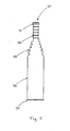
- Fig. 5 is a side view of a product
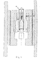
- Fig. 1 discloses a cross-sectional view of an injection-molding tool for manufacturing a urisheath.
- the injection-molding tool 1 comprises a left, movable form section 2 and a right, fixed form section 3. It is mentioned that left and right and other directions are only in relation to Fig. 1 , while the injection molding tool may be arranged in any desired direction, vertically as shown in Fig. 1 or 90° or 180° in relation to the position shown in Fig. 1 .
- the injection-molding tool may alternatively comprise one or several form sections.
- Each form section 2, 3 comprise one or several support plates 4, 5 and a heat-insulating plate 6.
- the support plates 4, 5 and the insulating plate 6 together support a form plate 7.
- Form plate 7 comprises a recess 8 in which an insertion plate 9 is arranged.
- the insertion plate 9 is provided with recesses or shapes that form the outer shape of the product to be formed, i.e. the urisheath, or at least a part of the outer shape thereof.
- Form section 2 and 3 are designed in a corresponding way, which is not described in detail here other than when there are differences between the form sections 2 and 3.
- a core 10 is arranged and shaped for defining the inner dimensions of the urisheath.
- Form plates 7 of form sections 2, 3 are heated by electrical heaters (not shown), arranged in the form plates 7.
- core 10 is heated by an electrical heater (not shown) inserted in the center of the core.
- electrical heaters e.g. hot water or oil under pressure circulating in a duct system in the form plates and the core.
- An injection nozzle 20 is arranged in the fixed form section 3 for injection of material into a cavity formed between core 10 and the form plates 9 of form sections 2 and 3.
- the nozzle is arranged at one end of the cavity, the proximal end of the proximal portion 15 of the cavity.
- the injection nozzle may be designed as shown in EP 710 535 , the contents of which is incorporated herein by reference.
- the injection nozzle is fixed in the cold support plates 5, 4 of the form section 3 and extends through the insulating plate 6 into the hot region of form plate 7 of the form section 3.
- the injection nozzle 20 comprises a central injection channel 21 having a diameter of e.g. 2 mm as shown in Fig. 2 . Exterior of the injection channel there is arranged a cooling jacket 22 enclosing several cooling channels 27 for a cooling medium such as water. Thus, the injection channel is maintained at a low temperature over its entire length.
- the injection channel ends in an injection channel portion 23 with a reduced diameter.
- the injection channel with reduced diameter ends slightly before an injection opening 24 to a cavity.
- An end portion 25 of the injection nozzle is supported by side walls 26 and forms a small cavity 29 which is filled by the injection material, which thereby forms a heat insulation for maintaining the reduced diameter channel portion 23 at a low temperature.
- the injection material can be fed to the injection cavity at a low temperature of e.g. about 25°C.
- Cold water is introduced in cooling channels 27 via a supply channel 30.
- the nozzle 20 is sealed by several O-ring sealings 28.
- the side walls 26 supporting the end portion 25 of the injection nozzle may be arranged in an insert 31 which is replaceable, so that injection nozzles having different diameters and shapes may be used in the same form section by exchanging the insert 31 and the injection nozzle 20.
- the proximal portion 15 of the cavity is designed to form the tip portion 52 of the urisheath, shown in fig 5 , having a relatively large wall thickness.
- the distal portion 17 of the cavity is designed to form the cylindrical portion 54 of the urisheath.
- the cavity has a narrow cross-sectional area, resulting in a cylindrical portion having small wall thickness.
- the thickness of the cylindrical portion may be constant. However, if the cross-sectional area of the cavity has a decreasing radial dimension, resulting in a cylindrical portion having a reduced thickness towards the distal end of the cylindrical portion, some advantages are added to the product.
- a very thin urisheath will provide increased wearing comfort, as well as it may provide a more breathable product and thereby increasing the skin friendliness.
- a larger thickness in the proximal end of the cylindrical portion prevents the urisheath from ballooning when in use, and thereby prevents a radial force on the adhesive, which eventually can loosen the adhesive from the skin and be the cause for a leakage.
- the cylindrical portion may have a constant radius or may have certain conicity.
- Fig. 1 shows the injection-molding tool in a closed position ready for injection of material in the cavity. This takes place by feeding material through the injection nozzle 20 to the cavity. The material is injected into the proximal portion 15 as seen in Fig. 1 .
- the proximal portion corresponds to the tip portion 52 of the ready-made urisheath.
- the tip portion has the largest wall thickness.
- the proximal end of the proximal portion 15 has an enlarged portion 18, in which the injected material can be distributed circumferentially around the entire periphery of the cavity. This ensures that the cavity is filled with material in a uniform manner.
- the enlarged portion 18 forms a protruding push rim 51 on the urisheath, shown in Fig. 5 .
- This protruding push rim protrudes outwards in a radial direction from the tip portion 52.
- the protruding push rim is usable when removing the urisheath from the form.
- the protruding push rim may provide frictional engagement for handling of the product during use. This is useful when connecting the urisheath to a urine bag.
- the push rim may, in an alternative embodiment, extend inwards partially, i.e. extend both inwards and outwards in the radial direction.
- the enlarged portion 18 in the cavity forms an area for receiving the material injected into the cavity and distribute the material around the periphery of the enlarged portion before the material proceeds downward into the rest of the cavity. The material then proceeds downward essentially parallel at all sides of the cavity. Thus, the air in the cavity is expelled more easily and uniformly, which means that the risk of entrapping air inside the cavity is reduced or completely eliminated.
- the material proceeds downward inside the cavity and finally reaches the distal end of the distal portion 17 of the cavity.
- An overflow area 13 is arranged at the distal end of the distal portion of the cavity. When the material reaches the overflow area, some material proceeds out in said area. In this way, it is assured that the cavity is always completely filled. Moreover, any air inside the cavity is expelled through the overflow area 13.
- the overflow area 13 may be connected to a space 12 via one or several channels 11 as shown in Fig. 3 .
- the cavity ends with a peripheral slit or groove 14, which is connected to the overflow area 13 over at least a portion. Thus, air inside the cavity is moved downward as seen in Fig. 1 to the groove 14 and further to the overflow area 13 and the space 12 via channel 11.
- the material collected in the groove 14 may form an outer roll rib 55 on the urisheath, shown in fig 5 .
- the roll rib may facilitate the handling of the urisheath after the production process.
- the roll rib gives good quality of the rolling, without wrinkles, and thus gives good unrolling for the user, and thereby secures a proper attachment on the user without having any wrinkles on the urisheath. This is essential for preventing a leakage.
- the roll rib may also increase the durability of the urisheath since the thin wall of the cylindrical portion 54 may have low tear strength and the roll rib may strengthen the distal end portion of cylindrical portion 54 of the urisheath.
- the material, which is collected in the overflow area 13, may simply be removed after the curing of the urisheath, such as during removal of the urisheath from the core.
- the overflow area 13 may extend over a portion of the periphery of the core or insert, such as over almost 180° as shown in Fig. 3 , or over a smaller portion, such as 90°.
- the space 12 may be sufficiently large to accommodate the air that needs to be expelled from the cavity, or may be connected to the atmosphere.
- the overflow area 13 may not be required, but the channel 11 and the space 12 may accommodate the surplus air.
- the material may be a liquid silicone elastomer material, such as a liquid silicone rubber LSR or a solid silicone (HCR, high consistency rubber).
- a silicone elastomer is used because it has a relatively high gas permeability compared to for example thermoplastics. Moreover, it includes no phthalates or other organic plasticizers that may be harmful for the user or the environment. The material is heat stable and may be autoclaved.
- a silicone elastomer No. C6-530 marketed by Dow Corning Co.
- the material is a two-component, platinum-catalyzed liquid silicone rubber elastomer. The two components are mixed in equal proportions, which are thoroughly blended.
- the elastomer is thermally cured via an addition-cure, platinum-catalyzed reaction.
- the resulting elastomer consists of cross-linked dimethyl and methyl-vinyl siloxane copolymers and reinforcing silica.
- the elastomer can be used without any post-cure.
- the elastomers are heat stable up to 204°C. Airless mixing, metering and dispensing equipment are recommended for production operations. Cure of the mixed elastomer is accelerated by heat. This material has been shown to be particularly suitable for the purpose of the present invention.
- the material is injected in a cold state by the coldrun nozzle 20.
- the temperature of the material before being injected is between 5°C and 50°C, specifically between 15°C and 40°C, more specifically between 20°C and 30°C, still more specifically about 25°C.
- the form plates surrounding the cavity are heated to a temperature of between 80°C and 200°C, specifically between 100°C and 160°C, more specifically between 110°C and 150°C, still more specifically between 135°C and 145°C.
- the material is injected rapidly into the cavity under high pressure of more than 1000 Bar, such as between 1500 to 2200 Bar. At this pressure, the material is a slightly viscous flowing material that can be injected at room temperature.
- the material fills the cavity in less than a second, such as less than a few tenths of a second.
- the material cures rapidly, in less than three seconds.
- the material is metered by a pump, not shown, so that a sufficient quantity is injected to fill the cavity.
- the injection can be time operated, so that injection takes place a sufficient time period to fill the cavity.
- the form is opened as shown in Figs. 3 and 4 .
- the injection-molded urisheath may be removed by grasping it at the enlarged tip portion 52 at the top of the core by a remover 40, as shown in Fig. 4 .
- the remover 40 comprises a grip member 41 which may grasp the urisheath.
- the grip member comprises ridges, which interfere with small ribs arranged at the outer surface of the tip portion 52 of the urisheath.
- the grip member is arranged in a sleeve 42, which is moved down over the urisheath, when the form is opened.
- air under pressure may be injected to make free the urisheath from the core and aid in the removal of the urisheath.
- the remover pulls the urisheath from the core. Since the urisheath is elastic, it is no problem to withdraw it from the core, although the urisheath includes some portions that have to expand to pass the core, viz. pleated or folded portions in the middle part 53 connecting the tip portion 52 with the cylindrical portion 54 as shown in fig 5 . Any material extending into the overflow area 13 may be cut off or torn off during the pulling out of the urisheath.
- the cylindrical portion of the urisheath may be rolled before removing the urisheath from the core, which will make easier the removal of the urisheath from the core.
- the remover includes an indication device 42, 43 for indicating that the entire urisheath has been removed and that no material is left in the cavity. This may be accomplished by sensors, such as LED:s and light sensors arranged to measure the entire length of the urisheath after removal from the core. If the urisheath has the expected length over the entire periphery, it is an indication that no material has been left in the cavity.
- the urisheath may be exposed to further treatments after the production, either immediately, or at another site.
- Such later treatment may be the addition of an adhesive material and rolling the cylindrical portion.
- any material left in the overflow area 13 is removed, for example by introducing airflow into the area 13 and the channel/s 11. Thus, the removal of such material is ensured. This ensures that any material left from the previous injection molding operation, do not interfere with the closing operation of the form plates and cavity. Then, the cavity is closed in the opposite order for the next cycle.
- the injection machine has several guides for controlling the movement of the form portions so that no jamming may occur.
- the mold portions are manufactured with a very high precision so that no or negligible burrs occur in the areas of intersection between the form portions.
- any residual material in the injection area should be as small as possible. Thus, the injection opening is made as small as possible, only some hundred micrometers.
- the material thickness in the cylindrical portion may be from 0.1 to 0.5 mm, such as 0.15 to 0.30 mm, for example, 0.25 mm.
- the inner surfaces of the form sections 2, 3 delimiting the cavity may be surface treated in order to provide a certain roughness of the product.
- the surface may be grit blasted to level out any sharp surface irregularities, for preventing that the surface of the product will be damaged when the product is removed.
- any pores in the cavity surface are closed.
- Grit blasting is a mold finishing process in which abrasive particles are blasted onto the mold surfaces in order to produce a roughened surface.
- the grit may consist of iron, aluminum oxide or any crushed or irregular abrasive.
- the blasted surface of the cavity will also provide a certain roughness of the surface of the ready-made product, which will prevent the product from adhering to it or to other products when they are stored or packed.
- the insertion plates 9 may be exchanged if a urisheath with another dimension should be manufactured.
- the core In order to remove the urisheath from the core, the core can be rotated 180° from the position shown in Fig. 4 , so that the tip portion faces downward.
- pivoting axes may be arranged.
- the entire procedure of injection molding the urisheath may take only about 30 to 40 seconds, which is the cycle time. If two or up to eight cores are arranged in parallel in the machine, a high capacity may be obtained. No post-curing is normally required. However, post-curing may be used for some types of material.
- a urisheath has been described.
- the same procedure may be used for producing other types of thin-walled products, such as a balloon or any hollow product having at least one opening.
- One such exemplifying product is a gastrobelt, which is a type of balloon for strangling the stomach.
Landscapes
- Engineering & Computer Science (AREA)
- Health & Medical Sciences (AREA)
- Mechanical Engineering (AREA)
- Manufacturing & Machinery (AREA)
- Veterinary Medicine (AREA)
- General Health & Medical Sciences (AREA)
- Public Health (AREA)
- Heart & Thoracic Surgery (AREA)
- Vascular Medicine (AREA)
- Life Sciences & Earth Sciences (AREA)
- Animal Behavior & Ethology (AREA)
- Nursing (AREA)
- Biomedical Technology (AREA)
- Epidemiology (AREA)
- Reproductive Health (AREA)
- Orthopedic Medicine & Surgery (AREA)
- Robotics (AREA)
- Moulds For Moulding Plastics Or The Like (AREA)
- Injection Moulding Of Plastics Or The Like (AREA)
- Pistons, Piston Rings, And Cylinders (AREA)
- Orthopedics, Nursing, And Contraception (AREA)
- Fuel-Injection Apparatus (AREA)
- Materials For Medical Uses (AREA)
Claims (3)
- Blasenkatheter-Endstück (50), umfassend einen Spitzenbereich (52) zur Verbindung mit einem Schlauch, der in einem Urinsammelbeutel endet, und einem zylindrischen Bereich (54) zum Einschließen eines Schafts eines Penis, wobei ein Schubrand (51) am Spitzenbereich (52), der sich in radialer Richtung nach außen vom Spitzenbereich (52) erstreckt, am Blasenkatheter-Endstück ausgebildet ist, dadurch gekennzeichnet, dass das Blasenkatheter-Endstück (50) spritzgegossen ist, und wobei eine äußere verrundete Rippe (55) an dem distalen Endbereich des zylindrischen Bereichs (54) auf dem Blasenkatheter-Endstück ausgebildet ist.
- Das Blasenkatheter-Endstück (50) nach Anspruch 1, wobei der zylindrische Bereich (54) mit einer verringerten Dicke in Richtung des distalen Endes des zylindrischen Bereichs (54) ausgebildet ist.
- Das Blasenkatheter-Endstück (50) nach Anspruch 1 oder 2, wobei das Blasenkatheter-Endstück (50) mit einer aufgerauten Oberfläche versehen ist.
Applications Claiming Priority (2)
| Application Number | Priority Date | Filing Date | Title |
|---|---|---|---|
| SE0502188 | 2005-10-03 | ||
| EP06799723.9A EP1931505B1 (de) | 2005-10-03 | 2006-10-03 | Verfahren und maschine zur herstellung einer harnableitungsvorrichtung |
Related Parent Applications (2)
| Application Number | Title | Priority Date | Filing Date |
|---|---|---|---|
| EP06799723.9 Division | 2006-10-03 | ||
| EP06799723.9A Division EP1931505B1 (de) | 2005-10-03 | 2006-10-03 | Verfahren und maschine zur herstellung einer harnableitungsvorrichtung |
Publications (3)
| Publication Number | Publication Date |
|---|---|
| EP2095799A2 EP2095799A2 (de) | 2009-09-02 |
| EP2095799A3 EP2095799A3 (de) | 2010-04-07 |
| EP2095799B1 true EP2095799B1 (de) | 2013-04-03 |
Family
ID=37906404
Family Applications (2)
| Application Number | Title | Priority Date | Filing Date |
|---|---|---|---|
| EP06799723.9A Active EP1931505B1 (de) | 2005-10-03 | 2006-10-03 | Verfahren und maschine zur herstellung einer harnableitungsvorrichtung |
| EP09156101A Active EP2095799B1 (de) | 2005-10-03 | 2006-10-03 | Spritzgegossene Harnableitungsvorrichtung |
Family Applications Before (1)
| Application Number | Title | Priority Date | Filing Date |
|---|---|---|---|
| EP06799723.9A Active EP1931505B1 (de) | 2005-10-03 | 2006-10-03 | Verfahren und maschine zur herstellung einer harnableitungsvorrichtung |
Country Status (7)
| Country | Link |
|---|---|
| US (2) | US8821780B2 (de) |
| EP (2) | EP1931505B1 (de) |
| JP (2) | JP2009509805A (de) |
| CN (2) | CN101291790A (de) |
| AU (2) | AU2006297891B2 (de) |
| CA (1) | CA2624878A1 (de) |
| WO (1) | WO2007040441A1 (de) |
Families Citing this family (7)
| Publication number | Priority date | Publication date | Assignee | Title |
|---|---|---|---|---|
| AU2006297891B2 (en) * | 2005-10-03 | 2012-01-19 | Nolato Meditech Ab | Method and machine for producing a hollow product |
| CA2644531A1 (en) | 2006-03-01 | 2007-09-07 | Coloplast A/S | Urisheath with moulded unrolling strip |
| US20110137272A1 (en) * | 2009-12-03 | 2011-06-09 | Medical Action Industries, Incorporated | Safety Ring Lid Closure |
| CN102950714B (zh) * | 2011-08-31 | 2014-11-19 | 吴江市荣顺精密铸件有限公司 | 一种连接座的注塑模具 |
| US8721322B2 (en) | 2011-11-30 | 2014-05-13 | Johnson & Johnson Vision Care, Inc. | Injection molding device and method |
| US9874022B2 (en) * | 2014-03-24 | 2018-01-23 | Oatey Co. | Moldable roof flashing |
| CN106671328B (zh) * | 2015-11-10 | 2019-09-03 | 无锡市凯顺医疗器械制造有限公司 | 一种模具及在开模过程中实现抽芯的方法 |
Family Cites Families (77)
| Publication number | Priority date | Publication date | Assignee | Title |
|---|---|---|---|---|
| DE1026044B (de) | 1957-03-22 | 1958-03-13 | Charlotte Staege Geb Rensch | Abrollbarer elastischer Hohlkoerper, wie Fingerling, Praeservativ |
| US2940450A (en) * | 1957-08-20 | 1960-06-14 | Urex Company | Male urine drain |
| US3608552A (en) * | 1970-02-05 | 1971-09-28 | Arthur B Broerman | Male urinal device |
| US3901965A (en) * | 1972-02-14 | 1975-08-26 | Iii Henry W Honeyman | Method of making an inflatable catheter |
| US3835857A (en) * | 1973-02-12 | 1974-09-17 | Rogers Ind Inc | Male urinal device |
| US4041122A (en) | 1976-06-01 | 1977-08-09 | International Paper Company | Process for molding of hollow articles |
| IE52880B1 (en) * | 1981-06-05 | 1988-03-30 | Hollister Inc | A male urinary collection system and axternal catheter therefor |
| US4378018A (en) | 1981-06-05 | 1983-03-29 | Hollister Incorporated | Male urinary drainage device |
| US4581026A (en) | 1981-06-05 | 1986-04-08 | Hollister Incorporated | Male urinary collection system and external catheter therefor |
| JPS581529U (ja) * | 1981-06-25 | 1983-01-07 | エヌオーケー株式会社 | ゴム成形品用離型装置 |
| JPS581529A (ja) | 1981-06-26 | 1983-01-06 | Yoji Araki | 中空成形機において2室以上ある容器を一体成形する方法及び装置 |
| US4475910A (en) | 1981-10-02 | 1984-10-09 | Mentor Corporation | Male condom catheter having adhesive transfer on roller portion |
| IT1152962B (it) | 1982-06-11 | 1987-01-14 | Manuli Autoadesivi Spa | Perfezionamento dei nastri autoadesivi con supporto in polipropilene od altro polimero o copolimero olefinico e relativo procedimento di fabbricazione |
| US4594761A (en) * | 1984-02-13 | 1986-06-17 | General Electric Company | Method of fabricating hollow composite airfoils |
| EP0162037B1 (de) | 1984-03-21 | 1989-04-26 | Franz Sterner | Verfahren zum Herstellen von Spritzgussteilen und Spritzgussform zur Durchführung des Verfahrens |
| JPS60229716A (ja) | 1984-04-27 | 1985-11-15 | Toyoda Gosei Co Ltd | 筒状ゴム製品の取出装置 |
| US4734241A (en) | 1984-09-26 | 1988-03-29 | Synergist Limited | Method for protecting a pre-formed projecting appendage during plastic molding |
| JPS61277419A (ja) * | 1985-06-03 | 1986-12-08 | Nissan Motor Co Ltd | 射出成形用金型 |
| JPS6270012A (ja) * | 1985-09-24 | 1987-03-31 | Matsushita Electric Works Ltd | 電子部品封止成形における成形品取り出し装置 |
| US4865595A (en) | 1986-02-28 | 1989-09-12 | Heyden Eugene L | Drainage device for urine |
| JPH0233765Y2 (de) | 1986-09-12 | 1990-09-11 | ||
| JPH01110116A (ja) * | 1987-10-24 | 1989-04-26 | Mitsubishi Monsanto Chem Co | 中空成形品の成形装置 |
| JP2537528B2 (ja) * | 1987-12-24 | 1996-09-25 | 三菱化学株式会社 | 2−(0−アミノフェニル)エタノ―ルの製造法 |
| US5829440A (en) | 1989-01-23 | 1998-11-03 | Broad, Jr.; Robert L. | Contracepive device and methods and apparatus for assembling the same |
| US4972850A (en) | 1989-01-23 | 1990-11-27 | Broad Jr Robert L | No hands contraceptive device |
| US5459879A (en) | 1989-05-22 | 1995-10-24 | Board Of Regents, The University Of Texas System | Protective coverings |
| US4934382A (en) | 1989-07-03 | 1990-06-19 | Barone Jr Richard J | Protective sheath with manipulation tabs |
| FR2649315A1 (fr) | 1989-07-10 | 1991-01-11 | Action Musicale Internationale | Preservatif masculin perfectionne |
| JPH0333617U (de) * | 1989-08-09 | 1991-04-03 | ||
| DK120190A (da) | 1990-05-15 | 1991-11-16 | Coloplast As | Elastisk hylsterformet indretning, navnlig uridom samt fremgangsmaade og apparat til fremstilling heraf |
| JPH0624745B2 (ja) * | 1990-05-15 | 1994-04-06 | 信越化学工業株式会社 | 乳首の製造方法 |
| US5334175A (en) | 1990-11-09 | 1994-08-02 | Rochester Medical Corporation | Male urinary incontinence device |
| US5176666A (en) | 1990-11-09 | 1993-01-05 | Rochester Medical Corporation | External urinary catheter having integral adhesive means |
| WO1992008426A1 (en) | 1990-11-09 | 1992-05-29 | Rochester Medical Corporation | External urinary catheter having integral adhesive means |
| US5163448A (en) * | 1991-04-30 | 1992-11-17 | Family Health International | Condom comprising dispensing structure, and method of making and using the same |
| DK121791D0 (da) | 1991-06-21 | 1991-06-21 | Coloplast As | Anordning til opsamling af urin |
| EP0601058A4 (de) | 1991-08-27 | 1995-05-31 | Cygnus Therapeutic Systems | Transdermale formulierungen zur prazosinverabreichung. |
| US5779964A (en) | 1991-09-03 | 1998-07-14 | Mentor Corporation | Method of making a male catheter |
| GB9222865D0 (en) * | 1992-10-31 | 1992-12-16 | Smith & Nephew | Medical apparatus |
| JPH072019U (ja) * | 1993-06-10 | 1995-01-13 | しなのポリマー株式会社 | 押釦スイッチ用カバー部材成形用金型 |
| JPH079317A (ja) | 1993-06-30 | 1995-01-13 | Hitachi Chem Co Ltd | 面取り研削された繊維強化プラスチック管の製造法および繊維強化プラスチック管の面取り研削装置 |
| DK79493A (da) * | 1993-07-02 | 1995-01-03 | Coloplast As | Eksternt urinkateter |
| GB2286339A (en) | 1994-02-02 | 1995-08-16 | Squibb & Sons Inc | Male incontinence device |
| AT401253B (de) | 1994-11-07 | 1996-07-25 | Rico Elastomere Projecting Gmb | Spritzgussform |
| JPH08252277A (ja) | 1995-03-16 | 1996-10-01 | Nobuko Uchiyama | 装着を容易にしたコンドーム |
| FR2734754A1 (fr) * | 1995-05-31 | 1996-12-06 | Ugray Claude | Procede et dispositif de fabrication d'une prothese chirurgicale a coque creuse et souple |
| JPH08336842A (ja) * | 1995-06-14 | 1996-12-24 | Toyoda Gosei Co Ltd | 成形品及びその製造方法並びに成形用金型装置 |
| US5713880A (en) | 1996-04-02 | 1998-02-03 | Medpoint Corporation | External male catheter |
| IT1286978B1 (it) | 1996-04-29 | 1998-07-24 | Luca Passarelli | Profilattico fornito di due appendici laterali che permettono di indossarlo senza che vengano meneggiate direttamente le parti a |
| EP0946349A1 (de) | 1996-11-22 | 1999-10-06 | Ethicon, Inc. | Verfahren und vorrichtung zum herstellen von dünnwandigen gegenständen mit barriereeigenschaften |
| GB9624573D0 (en) | 1996-11-27 | 1997-01-15 | Delaney Gregory P | A male condom |
| JPH10183162A (ja) * | 1996-12-26 | 1998-07-14 | Kyodo Yushi Kk | シリコーンゴム製ブーツを有する等速ジョイント用グリース組成物 |
| JP3640762B2 (ja) * | 1997-04-18 | 2005-04-20 | ジーイー東芝シリコーン株式会社 | 金型用ノズル |
| FR2771923A1 (fr) | 1997-12-04 | 1999-06-11 | Vincent Domenech | Systeme d'application de preservatifs |
| EP0979718A1 (de) | 1998-08-06 | 2000-02-16 | Franz Sterner | Verfahren zum Herstellen von Spritzgussteilen und Spritzgussform zur Durchführung des Verfahrens |
| JP2000232988A (ja) | 1998-12-08 | 2000-08-29 | Kazunori Tanabe | 新規なコンドーム包装体 |
| CH692980A5 (de) | 1999-01-21 | 2003-01-15 | Alcan Tech & Man Ag | Verpackung. |
| FR2794998B1 (fr) | 1999-06-21 | 2001-07-27 | Oreal | Organogels et leurs utilisations notamment cosmetiques |
| GB2357725A (en) * | 1999-12-02 | 2001-07-04 | Blatchford & Sons Ltd | Silicone cosmesis |
| US20020026163A1 (en) * | 2000-03-14 | 2002-02-28 | Reinhold Grundke | Male incontinence device, application tool, and methods of assembly |
| JP2002102110A (ja) | 2000-09-28 | 2002-04-09 | Kao Corp | 使い捨て排泄用容器 |
| AR027501A1 (es) | 2000-12-13 | 2003-04-02 | Sanchez Emilio Rufino | Dispositivo para el desenrollado y tendido de preservativos |
| DE60126822T2 (de) | 2001-01-03 | 2007-12-06 | Coloplast A/S | Externe harnkathetervorrichtung und verfahren zu ihrer herstellung |
| US6376432B1 (en) * | 2001-03-26 | 2002-04-23 | Exxonmobil Research And Engineering Company | Low friction grease for constant velocity universal joints, particularly plunging type joints that is compatible with silicone elastomer boots |
| WO2003005940A1 (en) | 2001-05-30 | 2003-01-23 | Michael Robert Matthis | Prophylactic device |
| JP2003211500A (ja) | 2002-01-23 | 2003-07-29 | Matsushita Electric Ind Co Ltd | プラスチックレンズの成形金型及び成形方法 |
| US6805690B2 (en) | 2002-05-10 | 2004-10-19 | Mentor Corporation | Male external catheters |
| EP1531877A1 (de) | 2002-07-08 | 2005-05-25 | Coloplast A/S | Externer harnkatheter |
| MY135504A (en) * | 2002-11-26 | 2008-04-30 | Inst Medical Res | Method for detecting sensitivity to acetycholine esterase in insects. |
| US20050101923A1 (en) | 2003-11-10 | 2005-05-12 | Leading Edge Innovations, Inc. | Male urinary incontinence sheath |
| WO2006021591A1 (en) | 2004-08-27 | 2006-03-02 | Coloplast A/S | Unrolling strips |
| JP2008511360A (ja) | 2004-08-30 | 2008-04-17 | コロプラスト アクティーゼルスカブ | 外部泌尿器カテーテル |
| ATE548998T1 (de) * | 2005-06-15 | 2012-03-15 | Hollister Inc | Aussensteckkatheter und herstellungsverfahren dafür |
| US20070000020A1 (en) * | 2005-06-30 | 2007-01-04 | Kimberly-Clark Worldwide, Inc. | Surgical glove with modified frictional interface and method for producing same |
| CN101309717A (zh) * | 2005-08-17 | 2008-11-19 | 科罗拉多州导管有限公司 | 导管插入术组件 |
| AU2006297891B2 (en) | 2005-10-03 | 2012-01-19 | Nolato Meditech Ab | Method and machine for producing a hollow product |
| CA2644531A1 (en) | 2006-03-01 | 2007-09-07 | Coloplast A/S | Urisheath with moulded unrolling strip |
-
2006
- 2006-10-03 AU AU2006297891A patent/AU2006297891B2/en not_active Ceased
- 2006-10-03 EP EP06799723.9A patent/EP1931505B1/de active Active
- 2006-10-03 EP EP09156101A patent/EP2095799B1/de active Active
- 2006-10-03 WO PCT/SE2006/001123 patent/WO2007040441A1/en active Application Filing
- 2006-10-03 CN CN 200680036469 patent/CN101291790A/zh active Pending
- 2006-10-03 US US12/089,031 patent/US8821780B2/en active Active
- 2006-10-03 JP JP2008533292A patent/JP2009509805A/ja active Pending
- 2006-10-03 CA CA002624878A patent/CA2624878A1/en not_active Abandoned
- 2006-10-03 CN CN 200910210612 patent/CN101703431A/zh active Pending
-
2009
- 2009-09-30 JP JP2009227969A patent/JP2010042680A/ja active Pending
- 2009-12-22 AU AU2009251092A patent/AU2009251092A1/en not_active Abandoned
-
2011
- 2011-01-19 US US13/009,381 patent/US20110118685A1/en not_active Abandoned
Also Published As
| Publication number | Publication date |
|---|---|
| US8821780B2 (en) | 2014-09-02 |
| EP1931505B1 (de) | 2013-07-10 |
| US20090118688A1 (en) | 2009-05-07 |
| CA2624878A1 (en) | 2007-04-12 |
| EP2095799A2 (de) | 2009-09-02 |
| EP2095799A3 (de) | 2010-04-07 |
| CN101703431A (zh) | 2010-05-12 |
| EP1931505A1 (de) | 2008-06-18 |
| CN101291790A (zh) | 2008-10-22 |
| EP1931505A4 (de) | 2010-04-07 |
| WO2007040441A1 (en) | 2007-04-12 |
| AU2006297891A1 (en) | 2007-04-12 |
| AU2009251092A1 (en) | 2010-01-28 |
| AU2006297891B2 (en) | 2012-01-19 |
| US20110118685A1 (en) | 2011-05-19 |
| JP2010042680A (ja) | 2010-02-25 |
| JP2009509805A (ja) | 2009-03-12 |
Similar Documents
| Publication | Publication Date | Title |
|---|---|---|
| EP2095799B1 (de) | Spritzgegossene Harnableitungsvorrichtung | |
| DK1420845T4 (en) | Process for the production of a catheter and a catheter | |
| US20190152109A1 (en) | Cushion, method of and apparatus for molding a cushion for a respiratory mask | |
| CN110621469B (zh) | 用于导尿管的注射模制的方法和设备 | |
| CN107441611B (zh) | 导尿管的制造方法 | |
| US5073347A (en) | Unitary volumetric pipette and method for making the same | |
| EP1904003B1 (de) | Aussensteckkatheter und herstellungsverfahren dafür | |
| EP0286320A2 (de) | Verfahren zum Herstellen eines Rohrleitungsmolchs mit einer texturierten rauhen Oberfläche | |
| JP2009509805A5 (de) | ||
| DE69906933D1 (de) | Rohrförmiges element zur entnahme von flüssigkeit sowie verfahren zu seiner herstellung | |
| EP3003188B1 (de) | Wärmeablationsgerät | |
| EP3718508B1 (de) | Form und formverfahren für körperimplantate, insbesondere für brustimplantate | |
| EP3220839B1 (de) | Vorrichtung für thermische ablation | |
| JPH06142241A (ja) | ゴルフクラブシャフトの製造方法 | |
| Peeters | Moulding Elastomers Using Heat-Destructible Polystyrene Core | |
| JPH0127847B2 (de) | ||
| WEISNER et al. | Method for molding structural parts utilizing modified silicone rubber(Patent Application) |
Legal Events
| Date | Code | Title | Description |
|---|---|---|---|
| PUAI | Public reference made under article 153(3) epc to a published international application that has entered the european phase |
Free format text: ORIGINAL CODE: 0009012 |
|
| AC | Divisional application: reference to earlier application |
Ref document number: 1931505 Country of ref document: EP Kind code of ref document: P |
|
| AK | Designated contracting states |
Kind code of ref document: A2 Designated state(s): AT BE BG CH CY CZ DE DK EE ES FI FR GB GR HU IE IS IT LI LT LU LV MC NL PL PT RO SE SI SK TR |
|
| AX | Request for extension of the european patent |
Extension state: AL BA HR MK RS |
|
| RIN1 | Information on inventor provided before grant (corrected) |
Inventor name: MAGNUSSON, PER-ERIK Inventor name: LINDENSKOV NIELSON, HENRIK |
|
| RAP1 | Party data changed (applicant data changed or rights of an application transferred) |
Owner name: COLOPLAST A/S |
|
| REG | Reference to a national code |
Ref country code: HK Ref legal event code: DE Ref document number: 1132168 Country of ref document: HK |
|
| PUAL | Search report despatched |
Free format text: ORIGINAL CODE: 0009013 |
|
| AK | Designated contracting states |
Kind code of ref document: A3 Designated state(s): AT BE BG CH CY CZ DE DK EE ES FI FR GB GR HU IE IS IT LI LT LU LV MC NL PL PT RO SE SI SK TR |
|
| AX | Request for extension of the european patent |
Extension state: AL BA HR MK RS |
|
| 17P | Request for examination filed |
Effective date: 20101007 |
|
| 17Q | First examination report despatched |
Effective date: 20101102 |
|
| AKX | Designation fees paid |
Designated state(s): AT BE BG CH CY CZ DE DK EE ES FI FR GB GR HU IE IS IT LI LT LU LV MC NL PL PT RO SE SI SK TR |
|
| RIC1 | Information provided on ipc code assigned before grant |
Ipc: B29C 45/42 20060101ALI20110510BHEP Ipc: A61F 5/453 20060101AFI20110510BHEP Ipc: B29C 45/27 20060101ALI20110510BHEP |
|
| GRAP | Despatch of communication of intention to grant a patent |
Free format text: ORIGINAL CODE: EPIDOSNIGR1 |
|
| GRAS | Grant fee paid |
Free format text: ORIGINAL CODE: EPIDOSNIGR3 |
|
| GRAA | (expected) grant |
Free format text: ORIGINAL CODE: 0009210 |
|
| AC | Divisional application: reference to earlier application |
Ref document number: 1931505 Country of ref document: EP Kind code of ref document: P |
|
| AK | Designated contracting states |
Kind code of ref document: B1 Designated state(s): AT BE BG CH CY CZ DE DK EE ES FI FR GB GR HU IE IS IT LI LT LU LV MC NL PL PT RO SE SI SK TR |
|
| REG | Reference to a national code |
Ref country code: GB Ref legal event code: FG4D |
|
| REG | Reference to a national code |
Ref country code: CH Ref legal event code: EP Ref country code: AT Ref legal event code: REF Ref document number: 604232 Country of ref document: AT Kind code of ref document: T Effective date: 20130415 |
|
| REG | Reference to a national code |
Ref country code: IE Ref legal event code: FG4D |
|
| REG | Reference to a national code |
Ref country code: DE Ref legal event code: R096 Ref document number: 602006035476 Country of ref document: DE Effective date: 20130529 |
|
| REG | Reference to a national code |
Ref country code: AT Ref legal event code: MK05 Ref document number: 604232 Country of ref document: AT Kind code of ref document: T Effective date: 20130403 |
|
| PG25 | Lapsed in a contracting state [announced via postgrant information from national office to epo] |
Ref country code: SI Free format text: LAPSE BECAUSE OF FAILURE TO SUBMIT A TRANSLATION OF THE DESCRIPTION OR TO PAY THE FEE WITHIN THE PRESCRIBED TIME-LIMIT Effective date: 20130403 |
|
| REG | Reference to a national code |
Ref country code: NL Ref legal event code: VDEP Effective date: 20130403 |
|
| REG | Reference to a national code |
Ref country code: LT Ref legal event code: MG4D |
|
| PG25 | Lapsed in a contracting state [announced via postgrant information from national office to epo] |
Ref country code: NL Free format text: LAPSE BECAUSE OF FAILURE TO SUBMIT A TRANSLATION OF THE DESCRIPTION OR TO PAY THE FEE WITHIN THE PRESCRIBED TIME-LIMIT Effective date: 20130403 Ref country code: IS Free format text: LAPSE BECAUSE OF FAILURE TO SUBMIT A TRANSLATION OF THE DESCRIPTION OR TO PAY THE FEE WITHIN THE PRESCRIBED TIME-LIMIT Effective date: 20130803 Ref country code: PT Free format text: LAPSE BECAUSE OF FAILURE TO SUBMIT A TRANSLATION OF THE DESCRIPTION OR TO PAY THE FEE WITHIN THE PRESCRIBED TIME-LIMIT Effective date: 20130805 Ref country code: SE Free format text: LAPSE BECAUSE OF FAILURE TO SUBMIT A TRANSLATION OF THE DESCRIPTION OR TO PAY THE FEE WITHIN THE PRESCRIBED TIME-LIMIT Effective date: 20130403 Ref country code: ES Free format text: LAPSE BECAUSE OF FAILURE TO SUBMIT A TRANSLATION OF THE DESCRIPTION OR TO PAY THE FEE WITHIN THE PRESCRIBED TIME-LIMIT Effective date: 20130714 Ref country code: BE Free format text: LAPSE BECAUSE OF FAILURE TO SUBMIT A TRANSLATION OF THE DESCRIPTION OR TO PAY THE FEE WITHIN THE PRESCRIBED TIME-LIMIT Effective date: 20130403 Ref country code: GR Free format text: LAPSE BECAUSE OF FAILURE TO SUBMIT A TRANSLATION OF THE DESCRIPTION OR TO PAY THE FEE WITHIN THE PRESCRIBED TIME-LIMIT Effective date: 20130704 Ref country code: FI Free format text: LAPSE BECAUSE OF FAILURE TO SUBMIT A TRANSLATION OF THE DESCRIPTION OR TO PAY THE FEE WITHIN THE PRESCRIBED TIME-LIMIT Effective date: 20130403 Ref country code: LT Free format text: LAPSE BECAUSE OF FAILURE TO SUBMIT A TRANSLATION OF THE DESCRIPTION OR TO PAY THE FEE WITHIN THE PRESCRIBED TIME-LIMIT Effective date: 20130403 Ref country code: AT Free format text: LAPSE BECAUSE OF FAILURE TO SUBMIT A TRANSLATION OF THE DESCRIPTION OR TO PAY THE FEE WITHIN THE PRESCRIBED TIME-LIMIT Effective date: 20130403 |
|
| PG25 | Lapsed in a contracting state [announced via postgrant information from national office to epo] |
Ref country code: CY Free format text: LAPSE BECAUSE OF FAILURE TO SUBMIT A TRANSLATION OF THE DESCRIPTION OR TO PAY THE FEE WITHIN THE PRESCRIBED TIME-LIMIT Effective date: 20130403 Ref country code: PL Free format text: LAPSE BECAUSE OF FAILURE TO SUBMIT A TRANSLATION OF THE DESCRIPTION OR TO PAY THE FEE WITHIN THE PRESCRIBED TIME-LIMIT Effective date: 20130403 Ref country code: LV Free format text: LAPSE BECAUSE OF FAILURE TO SUBMIT A TRANSLATION OF THE DESCRIPTION OR TO PAY THE FEE WITHIN THE PRESCRIBED TIME-LIMIT Effective date: 20130403 Ref country code: BG Free format text: LAPSE BECAUSE OF FAILURE TO SUBMIT A TRANSLATION OF THE DESCRIPTION OR TO PAY THE FEE WITHIN THE PRESCRIBED TIME-LIMIT Effective date: 20130703 |
|
| PG25 | Lapsed in a contracting state [announced via postgrant information from national office to epo] |
Ref country code: DK Free format text: LAPSE BECAUSE OF FAILURE TO SUBMIT A TRANSLATION OF THE DESCRIPTION OR TO PAY THE FEE WITHIN THE PRESCRIBED TIME-LIMIT Effective date: 20130403 Ref country code: EE Free format text: LAPSE BECAUSE OF FAILURE TO SUBMIT A TRANSLATION OF THE DESCRIPTION OR TO PAY THE FEE WITHIN THE PRESCRIBED TIME-LIMIT Effective date: 20130403 Ref country code: CZ Free format text: LAPSE BECAUSE OF FAILURE TO SUBMIT A TRANSLATION OF THE DESCRIPTION OR TO PAY THE FEE WITHIN THE PRESCRIBED TIME-LIMIT Effective date: 20130403 Ref country code: SK Free format text: LAPSE BECAUSE OF FAILURE TO SUBMIT A TRANSLATION OF THE DESCRIPTION OR TO PAY THE FEE WITHIN THE PRESCRIBED TIME-LIMIT Effective date: 20130403 |
|
| PLBE | No opposition filed within time limit |
Free format text: ORIGINAL CODE: 0009261 |
|
| STAA | Information on the status of an ep patent application or granted ep patent |
Free format text: STATUS: NO OPPOSITION FILED WITHIN TIME LIMIT |
|
| PG25 | Lapsed in a contracting state [announced via postgrant information from national office to epo] |
Ref country code: IT Free format text: LAPSE BECAUSE OF FAILURE TO SUBMIT A TRANSLATION OF THE DESCRIPTION OR TO PAY THE FEE WITHIN THE PRESCRIBED TIME-LIMIT Effective date: 20130403 Ref country code: RO Free format text: LAPSE BECAUSE OF FAILURE TO SUBMIT A TRANSLATION OF THE DESCRIPTION OR TO PAY THE FEE WITHIN THE PRESCRIBED TIME-LIMIT Effective date: 20130403 |
|
| 26N | No opposition filed |
Effective date: 20140106 |
|
| REG | Reference to a national code |
Ref country code: DE Ref legal event code: R097 Ref document number: 602006035476 Country of ref document: DE Effective date: 20140106 |
|
| PG25 | Lapsed in a contracting state [announced via postgrant information from national office to epo] |
Ref country code: MC Free format text: LAPSE BECAUSE OF FAILURE TO SUBMIT A TRANSLATION OF THE DESCRIPTION OR TO PAY THE FEE WITHIN THE PRESCRIBED TIME-LIMIT Effective date: 20130403 |
|
| REG | Reference to a national code |
Ref country code: CH Ref legal event code: PL |
|
| REG | Reference to a national code |
Ref country code: IE Ref legal event code: MM4A |
|
| PG25 | Lapsed in a contracting state [announced via postgrant information from national office to epo] |
Ref country code: CH Free format text: LAPSE BECAUSE OF NON-PAYMENT OF DUE FEES Effective date: 20131031 Ref country code: LI Free format text: LAPSE BECAUSE OF NON-PAYMENT OF DUE FEES Effective date: 20131031 |
|
| PG25 | Lapsed in a contracting state [announced via postgrant information from national office to epo] |
Ref country code: IE Free format text: LAPSE BECAUSE OF NON-PAYMENT OF DUE FEES Effective date: 20131003 |
|
| PG25 | Lapsed in a contracting state [announced via postgrant information from national office to epo] |
Ref country code: TR Free format text: LAPSE BECAUSE OF FAILURE TO SUBMIT A TRANSLATION OF THE DESCRIPTION OR TO PAY THE FEE WITHIN THE PRESCRIBED TIME-LIMIT Effective date: 20130403 |
|
| PG25 | Lapsed in a contracting state [announced via postgrant information from national office to epo] |
Ref country code: LU Free format text: LAPSE BECAUSE OF NON-PAYMENT OF DUE FEES Effective date: 20131003 Ref country code: HU Free format text: LAPSE BECAUSE OF FAILURE TO SUBMIT A TRANSLATION OF THE DESCRIPTION OR TO PAY THE FEE WITHIN THE PRESCRIBED TIME-LIMIT; INVALID AB INITIO Effective date: 20061003 |
|
| REG | Reference to a national code |
Ref country code: HK Ref legal event code: WD Ref document number: 1132168 Country of ref document: HK |
|
| REG | Reference to a national code |
Ref country code: FR Ref legal event code: PLFP Year of fee payment: 11 |
|
| REG | Reference to a national code |
Ref country code: FR Ref legal event code: PLFP Year of fee payment: 12 |
|
| REG | Reference to a national code |
Ref country code: FR Ref legal event code: PLFP Year of fee payment: 13 |
|
| REG | Reference to a national code |
Ref country code: DE Ref legal event code: R082 Ref document number: 602006035476 Country of ref document: DE Representative=s name: PATENTANWAELTE ISENBRUCK BOESL HOERSCHLER PART, DE |
|
| PGFP | Annual fee paid to national office [announced via postgrant information from national office to epo] |
Ref country code: GB Payment date: 20231010 Year of fee payment: 18 |
|
| PGFP | Annual fee paid to national office [announced via postgrant information from national office to epo] |
Ref country code: FR Payment date: 20231016 Year of fee payment: 18 Ref country code: DE Payment date: 20231016 Year of fee payment: 18 |