EP2094464B1 - Elektrische heizeinrichtung für heisskanalsysteme und verfahren zu ihrer herstellung - Google Patents
Elektrische heizeinrichtung für heisskanalsysteme und verfahren zu ihrer herstellung Download PDFInfo
- Publication number
- EP2094464B1 EP2094464B1 EP07801861A EP07801861A EP2094464B1 EP 2094464 B1 EP2094464 B1 EP 2094464B1 EP 07801861 A EP07801861 A EP 07801861A EP 07801861 A EP07801861 A EP 07801861A EP 2094464 B1 EP2094464 B1 EP 2094464B1
- Authority
- EP
- European Patent Office
- Prior art keywords
- layer
- heating device
- resistance wire
- hot runner
- insulating layer
- Prior art date
- Legal status (The legal status is an assumption and is not a legal conclusion. Google has not performed a legal analysis and makes no representation as to the accuracy of the status listed.)
- Active
Links
- 238000000034 method Methods 0.000 title claims description 19
- 238000004519 manufacturing process Methods 0.000 title claims description 8
- 238000005485 electric heating Methods 0.000 title claims 2
- 238000010438 heat treatment Methods 0.000 claims description 77
- 239000000463 material Substances 0.000 claims description 50
- 239000004020 conductor Substances 0.000 claims description 26
- 239000000919 ceramic Substances 0.000 claims description 11
- 239000002184 metal Substances 0.000 claims description 9
- 229910052751 metal Inorganic materials 0.000 claims description 9
- 238000007650 screen-printing Methods 0.000 claims description 9
- 229910000831 Steel Inorganic materials 0.000 claims description 4
- 229910001092 metal group alloy Inorganic materials 0.000 claims description 4
- 239000010959 steel Substances 0.000 claims description 4
- 150000001875 compounds Chemical class 0.000 claims description 3
- 230000001419 dependent effect Effects 0.000 claims description 3
- 229910000851 Alloy steel Inorganic materials 0.000 claims description 2
- 239000010410 layer Substances 0.000 description 86
- 238000000576 coating method Methods 0.000 description 7
- 239000011248 coating agent Substances 0.000 description 5
- 238000010276 construction Methods 0.000 description 5
- 238000013461 design Methods 0.000 description 5
- 238000005516 engineering process Methods 0.000 description 5
- 230000002349 favourable effect Effects 0.000 description 5
- 239000011521 glass Substances 0.000 description 5
- 238000012546 transfer Methods 0.000 description 4
- 229910001315 Tool steel Inorganic materials 0.000 description 3
- 238000009826 distribution Methods 0.000 description 3
- 238000001746 injection moulding Methods 0.000 description 3
- 239000002346 layers by function Substances 0.000 description 3
- 238000007639 printing Methods 0.000 description 3
- 229910018072 Al 2 O 3 Inorganic materials 0.000 description 2
- PXHVJJICTQNCMI-UHFFFAOYSA-N Nickel Chemical compound [Ni] PXHVJJICTQNCMI-UHFFFAOYSA-N 0.000 description 2
- 229910004298 SiO 2 Inorganic materials 0.000 description 2
- 238000000137 annealing Methods 0.000 description 2
- 238000001816 cooling Methods 0.000 description 2
- 230000000694 effects Effects 0.000 description 2
- 238000010292 electrical insulation Methods 0.000 description 2
- 230000009969 flowable effect Effects 0.000 description 2
- 229910044991 metal oxide Inorganic materials 0.000 description 2
- 150000004706 metal oxides Chemical class 0.000 description 2
- 239000002994 raw material Substances 0.000 description 2
- 239000007787 solid Substances 0.000 description 2
- 230000035882 stress Effects 0.000 description 2
- 238000004804 winding Methods 0.000 description 2
- 239000000853 adhesive Substances 0.000 description 1
- 230000001070 adhesive effect Effects 0.000 description 1
- PNEYBMLMFCGWSK-UHFFFAOYSA-N aluminium oxide Inorganic materials [O-2].[O-2].[O-2].[Al+3].[Al+3] PNEYBMLMFCGWSK-UHFFFAOYSA-N 0.000 description 1
- QVQLCTNNEUAWMS-UHFFFAOYSA-N barium oxide Inorganic materials [Ba]=O QVQLCTNNEUAWMS-UHFFFAOYSA-N 0.000 description 1
- 230000005540 biological transmission Effects 0.000 description 1
- 230000015572 biosynthetic process Effects 0.000 description 1
- 238000009529 body temperature measurement Methods 0.000 description 1
- 239000012876 carrier material Substances 0.000 description 1
- 238000010344 co-firing Methods 0.000 description 1
- 239000002131 composite material Substances 0.000 description 1
- 239000000470 constituent Substances 0.000 description 1
- 239000002178 crystalline material Substances 0.000 description 1
- 230000032798 delamination Effects 0.000 description 1
- 238000005474 detonation Methods 0.000 description 1
- 238000003618 dip coating Methods 0.000 description 1
- 238000007598 dipping method Methods 0.000 description 1
- 230000005489 elastic deformation Effects 0.000 description 1
- 238000005265 energy consumption Methods 0.000 description 1
- 238000011065 in-situ storage Methods 0.000 description 1
- 238000002347 injection Methods 0.000 description 1
- 239000007924 injection Substances 0.000 description 1
- 239000000203 mixture Substances 0.000 description 1
- 238000012986 modification Methods 0.000 description 1
- 230000004048 modification Effects 0.000 description 1
- 229910052759 nickel Inorganic materials 0.000 description 1
- 238000013021 overheating Methods 0.000 description 1
- 239000004033 plastic Substances 0.000 description 1
- 238000012545 processing Methods 0.000 description 1
- 238000007788 roughening Methods 0.000 description 1
- 239000000126 substance Substances 0.000 description 1
- 238000005494 tarnishing Methods 0.000 description 1
- 230000008646 thermal stress Effects 0.000 description 1
- 229920001169 thermoplastic Polymers 0.000 description 1
- 239000004416 thermosoftening plastic Substances 0.000 description 1
- 230000009466 transformation Effects 0.000 description 1
- 238000009736 wetting Methods 0.000 description 1
Images


Classifications
-
- B—PERFORMING OPERATIONS; TRANSPORTING
- B29—WORKING OF PLASTICS; WORKING OF SUBSTANCES IN A PLASTIC STATE IN GENERAL
- B29C—SHAPING OR JOINING OF PLASTICS; SHAPING OF MATERIAL IN A PLASTIC STATE, NOT OTHERWISE PROVIDED FOR; AFTER-TREATMENT OF THE SHAPED PRODUCTS, e.g. REPAIRING
- B29C45/00—Injection moulding, i.e. forcing the required volume of moulding material through a nozzle into a closed mould; Apparatus therefor
- B29C45/17—Component parts, details or accessories; Auxiliary operations
- B29C45/72—Heating or cooling
- B29C45/74—Heating or cooling of the injection unit
-
- B—PERFORMING OPERATIONS; TRANSPORTING
- B29—WORKING OF PLASTICS; WORKING OF SUBSTANCES IN A PLASTIC STATE IN GENERAL
- B29C—SHAPING OR JOINING OF PLASTICS; SHAPING OF MATERIAL IN A PLASTIC STATE, NOT OTHERWISE PROVIDED FOR; AFTER-TREATMENT OF THE SHAPED PRODUCTS, e.g. REPAIRING
- B29C45/00—Injection moulding, i.e. forcing the required volume of moulding material through a nozzle into a closed mould; Apparatus therefor
- B29C45/17—Component parts, details or accessories; Auxiliary operations
- B29C45/26—Moulds
- B29C45/27—Sprue channels ; Runner channels or runner nozzles
- B29C45/2737—Heating or cooling means therefor
-
- B—PERFORMING OPERATIONS; TRANSPORTING
- B29—WORKING OF PLASTICS; WORKING OF SUBSTANCES IN A PLASTIC STATE IN GENERAL
- B29C—SHAPING OR JOINING OF PLASTICS; SHAPING OF MATERIAL IN A PLASTIC STATE, NOT OTHERWISE PROVIDED FOR; AFTER-TREATMENT OF THE SHAPED PRODUCTS, e.g. REPAIRING
- B29C45/00—Injection moulding, i.e. forcing the required volume of moulding material through a nozzle into a closed mould; Apparatus therefor
- B29C45/17—Component parts, details or accessories; Auxiliary operations
- B29C45/26—Moulds
- B29C45/27—Sprue channels ; Runner channels or runner nozzles
- B29C45/2737—Heating or cooling means therefor
- B29C2045/274—Thermocouples or heat sensors
-
- B—PERFORMING OPERATIONS; TRANSPORTING
- B29—WORKING OF PLASTICS; WORKING OF SUBSTANCES IN A PLASTIC STATE IN GENERAL
- B29C—SHAPING OR JOINING OF PLASTICS; SHAPING OF MATERIAL IN A PLASTIC STATE, NOT OTHERWISE PROVIDED FOR; AFTER-TREATMENT OF THE SHAPED PRODUCTS, e.g. REPAIRING
- B29C45/00—Injection moulding, i.e. forcing the required volume of moulding material through a nozzle into a closed mould; Apparatus therefor
- B29C45/17—Component parts, details or accessories; Auxiliary operations
- B29C45/26—Moulds
- B29C45/27—Sprue channels ; Runner channels or runner nozzles
- B29C45/2737—Heating or cooling means therefor
- B29C2045/2743—Electrical heating element constructions
- B29C2045/2748—Insulating layers covering the electrical heating element
-
- Y—GENERAL TAGGING OF NEW TECHNOLOGICAL DEVELOPMENTS; GENERAL TAGGING OF CROSS-SECTIONAL TECHNOLOGIES SPANNING OVER SEVERAL SECTIONS OF THE IPC; TECHNICAL SUBJECTS COVERED BY FORMER USPC CROSS-REFERENCE ART COLLECTIONS [XRACs] AND DIGESTS
- Y10—TECHNICAL SUBJECTS COVERED BY FORMER USPC
- Y10T—TECHNICAL SUBJECTS COVERED BY FORMER US CLASSIFICATION
- Y10T29/00—Metal working
- Y10T29/49—Method of mechanical manufacture
- Y10T29/49002—Electrical device making
- Y10T29/49082—Resistor making
- Y10T29/49083—Heater type
Definitions
- the invention relates to an electrical heating device for hot runner systems, in particular for hot runner nozzles and / or hot runner manifolds.
- Hot runner systems are used in injection molds in order to supply a flowable mass - for example a plastic melt - at a predeterminable temperature under high pressure to a separable mold insert. They usually have a material tube with a flow channel that ends in a nozzle orifice. The latter forms a nozzle outlet opening at the end, which opens via a gate in the mold insert (mold cavity). So that the flowable mass does not cool prematurely within the material tube, one or more electrical heating devices are provided which ensure a temperature distribution which is as uniform as possible into the nozzle mouthpiece.
- the electrical heating device may be formed, for example, as a separate component with a helical heating element, which is integrated in a tubular sheath and peripherally on the material pipe can be placed.
- the sheathing is, as in DE-U-295 07 848 or US Patent No. 4,558,210 discloses a rigid structure formed by additional holding or clamping elements on the material tube in axial direction is determined.
- one can form the heater as a flexible heating strip or flexible heating mat between electrically insulating layers with optionally different thermal conductivity, which are fixed on the outer circumference of the material tube.
- EP-B1-0 028 153 this provides heat-conducting adhesive strips, while WO 97/03540 flexible straps used with Velcro or snap fasteners.
- a disadvantage of these known heaters is the relatively large dimensions, so that the hot runner nozzles when installing a lot of space must be made available, which is not desirable in most applications, especially when small nest spacings are required.
- the relatively large dimensions also require a higher heating power, which has a negative impact on energy consumption.
- the large thermal masses extend the heating and cooling phases, resulting in limitations in terms of increased productivity rates.
- the heating device takes up only a small amount of space overall, so that extremely compact designs can be realized in comparison to the aforementioned heating devices with almost identical performance features.
- the power density can be increased significantly, since the heat is generated and removed directly on the surface of the hot runner element to be heated. Overheating of the most sensitive heating elements is thereby avoided.
- the nozzle can heat up quickly and precisely and also cool down again, which has a favorable effect on the entire production process.
- a disadvantage of these heaters is that the material selection for the heating layer is limited to the fact that only such materials may be used, the baking temperature is so low that the microstructure of the material pipe, which is usually made of tool steel and also exposed to the baking temperatures is not changed during the baking process. The stoving temperatures of the heating conductor layers must therefore not exceed the annealing temperature of the material raw material.
- the aim of the invention is to avoid these and other disadvantages of the prior art and to provide an improved heating device that is simple and inexpensive to produce.
- the aim is in particular a corresponding manufacturing method, an improved hot runner system and an improved hot runner nozzle.
- An electrical heating device for hot runner systems in particular for hot runner nozzles and / or hot runner manifold, according to the present invention, at least one tubular or sleeve-like support member carrying at least one heat conductor, wherein the heating conductor is formed by a resistance wire
- the entire heating device can be pushed onto a material pipe of a hot runner nozzle, resulting in a total two-part structure consisting of heating and material tube.
- the heater is correspondingly interchangeable.
- the entire heater occupies little space, so that can be realized in comparison to other heaters with almost the same performance features extremely compact hot runner nozzles.
- the heater can be easily and inexpensively manufactured, which has a favorable effect on the production costs.
- At least one electrically insulating cover layer is provided, which covers the heating conductor and the support element to the outside and electrically insulated.
- the covering layer is advantageously provided as the outermost layer of the heating device.
- the baking temperature is so low that the microstructure of the material pipe, which is usually made of tool steel and also exposed to the baking temperatures is not changed during the baking process. The stoving temperatures of the heating conductor layers must therefore not exceed the annealing temperature of the material raw material.
- WO 01/66333 A1 describes an electric heater, which is applied directly to the material tube of an injection molding nozzle, wherein a resistance wire over an electrical insulating layer, with which the material tube is coated, is spirally wound around the material tube.
- the resistance wire is covered with both a thermal and an electrical insulating layer.
- DE 103 33 206 A1 discloses an electric heater, which is provided with a continuous central fitting bore for the gap-free recording of an injection molding nozzle to be heated.
- the heater has an inner and an outer metal sheath. These form a frontally sealed annular chamber which is filled with a ceramic insulating compound or a metal oxide. In the mass or the metal oxide, a heating wire is embedded.
- the aim of the invention is to avoid these and other disadvantages of the prior art and to provide an improved heating device that is simple and inexpensive to produce.
- the aim is in particular a corresponding manufacturing method, an improved hot runner system and an improved hot runner nozzle.
- An electrical heating device for hot runner systems in particular for hot runner nozzles and / or hot runner manifold, according to the present invention, at least one tubular or sleeve-like support member carrying at least one heat conductor, wherein the heating conductor is formed by a resistance wire
- the entire heating device can be pushed onto a material pipe of a hot runner nozzle, resulting in a total two-part structure consisting of heating and material tube.
- the heater is correspondingly interchangeable. It results in a total compact design, which ensures a permanently fixed connection and thus a firm hold on the hot runner manifold or the hot runner nozzle. In any case, the entire heater occupies little space, so that can be realized in comparison to other heaters with almost the same performance features extremely compact hot runner nozzles. In addition, the heater can be easily and inexpensively manufactured, which has a favorable effect on the production costs.
- At least one electrically insulating cover layer is provided, which covers the heating conductor and the support element to the outside and electrically insulated.
- the covering layer is advantageously provided as the outermost layer of the heating device.
- At least one temperature sensor whose electrical resistance is temperature-dependent.
- the temperature sensor may be conventionally formed or formed as an electrically conductive layer whose electrical resistance is temperature-dependent.
- the actual temperature can be determined continuously, wherein the measured values can be used to control the heating device according to the invention.
- the serving as a temperature sensor layer preferably comprises a PTC or NTC material.
- a thermocouple is possible as a temperature sensor with the same structuring as a resistance sensor and the measuring point near the nozzle tip.
- the temperature sensor and the heating conductor are advantageously in the radial direction in a common plane, whereby the space of the heating device according to the invention can be additionally reduced.
- the support element is advantageously made of a sintered material, such as a ceramic or a sintered metal. But you can also use a metal metal alloy, a steel or a steel alloy.
- a ceramic has the advantage that the heating conductor or the resistance wire can be applied directly to the carrier element.
- a metal e.g. a tool steel, a cemented carbide or the like., Or a steel
- an insulating layer is disposed between the support member and the heating conductor to electrically isolate the resistance wire relative to the support member.
- such an insulating or intermediate layer can also be provided on a ceramic carrier element, for example to improve the adhesion.
- Both the cover layer and the insulating layer serving as the intermediate layer are preferably a glassy and / or ceramic dielectric layer, which is under compressive prestressing after at least one baking process, so that delamination forces occurring within the insulating layer at a different height are compensated for depending on the internal pressure of the carrier element ,
- the compressive prestressing is preferably generated by a respective specific mismatching of the linear expansion coefficient of the ceramic insulating layer TEC DE or the linear thermal expansion coefficient TEC DEA depending on the strain-relevant characteristics of the carrier element Cover layer is given to the corresponding value of the support element TEC M , wherein the differential expansion TEC DE -TEC M or TEC DEA -TEC M does not exceed a value of 5 ⁇ 10 -6 K -1 .
- the insulating layer and / or the covering layer preferably has the property of wetting the carrier surface at the respective stoving temperature. In certain circumstances, it is advantageous that the material system at least partially passes into the crystalline state.
- the insulating layer and / or the covering layer may comprise a glassy or glassy-crystalline material system which contains at least one preformed glass which wets the surface of the carrier element at a predefinable baking temperature.
- the material system may further comprise at least one preformed glass, which at least partially passes into a crystalline state at a predefinable baking temperature.
- the material system may contain at least one further glass which does not crystallize under stoving conditions and / or at least one a priori crystalline compound, wherein by optimizing the proportions of the preformed glassy and crystalline constituents of the material system taking into account their respective TEC increments under the conditions of the respective baking process, a ceramic dielectric layer with a TEC value in the range between 0 and 13 ⁇ 10 -6 K -1 is obtained.
- a compensation layer is arranged, which consists for example of chemical nickel. Such a compensation layer also serves to compensate for different thermal expansion coefficients between the carrier material and the insulating layer.
- the leveling layer can be applied in the same way as the insulating layer and the covering layer.
- the insulating layer, the covering layer and / or the leveling layer are baked-on films or baked thick-film pastes. Alternatively, a dip coating (dipping) with subsequent burn-in is possible.
- the resistance wire forms a Schuleiter Listel, wherein the formation and / or the arrangement of the resistance wire is adapted to the respective Schuzes station.
- This allows the in a particularly strong to be heated area be arranged to be arranged windings or turns of the resistance wire, for example, particularly dense, in order to introduce correspondingly more heat energy in this section.
- the resistance wire is also helical or meander-shaped, the helix pitch may also be selected to be smaller or larger, in sections, in order to vary the heat energy output.
- the cross section of the resistance wire can also vary as needed.
- a contact layer can be arranged between the insulating layer, the heating conductor and / or the temperature sensor. Also in this and / or in the temperature sensor and / or arranged between the carrier element and heat conductor insulating or adhesion-promoting intermediate layer (insulating layer) is preferably either baked-on films or baked thick-film pastes. These can be easily and inexpensively apply, in particular structure and handle, so that can produce extremely reliable and inexpensive heating device.
- the insulating layer and / or the covering layer and / or the compensating layer and / or the contact layer and / or the layer serving as a temperature sensor form a layer composite embedding the resistance wire, so that a compact construction of the heating device according to the invention is always achieved. This applies in particular when the resistance wire forming the heating conductor is embedded in the insulating layer and / or in the contact layer.
- the present invention further relates to a hot runner system, in particular a hot runner nozzle or a hot runner manifold with an electric heater of the type described above.
- the tubular or sleeve-like support member is on a material tube, a rod, a distributor, a nozzle or the like. put on or postponed.
- the present invention relates to a hot runner nozzle with an electric heater according to the invention, wherein the tubular or sleeve-like support member is mounted on a material pipe to form a fit with predetermined play.
- the carrier element may form the material tube, which has a favorable effect on the heat transfer.
- the present invention relates to a method for producing an electrical heating device according to the invention for hot runner systems, in particular for hot runner nozzles and / or hot runner manifold, wherein the heating wire forming resistance wire is applied to the support member and that subsequently the cover layer is applied by film or screen printing technology. Both the application of the resistance wire and the cover layer is easy to control and in combination surprisingly low feasible.
- the heater produced works precisely and permanently reliable, which has a favorable overall effect on the temperature distribution and the service life of the heating elements.
- the insulating layer is applied in film or screen printing technique on the support member before winding of the Schuleiterhausl forming resistance wire, wherein the resistance wire is suitably embedded in the insulating layer.
- the applied in screen printing technology layers are advantageously applied using the round printing technology in the form of pastes, which ensures a total economic process management.
- Each layer can be applied separately and then baked; the stoving temperature can vary for each layer.
- the baking temperature can also be varied individually for each layer and lowered after each baking step.
- a further embodiment of the method according to the invention provides that all layers are applied separately and baked simultaneously (co-firing).
- the burn-in temperature range is between 800 and 1400 ° C.
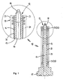
- hot runner nozzle 12 has as part of an injection molding system for thermoplastic processing for fixing to a (not shown distributor) (also not shown) housing, in which a total cylindrical material tube 13 is inserted in. A formed at this end base 17 terminates flush with the housing In the longitudinally extending material tube 13 in the axial direction, a nozzle tip 18 is inserted, preferably screwed in, which rotates the flow channel 14 formed in the material tube 13 as far as the plane (not shown) of a likewise invisible The nozzle tip 18 can also be formed in one piece with the material tube 13, even with the same mode of operation.
- a heater 10 is placed on the outer circumference of the wall 16 of the example made of steel material tube 13, a heater 10 is placed.
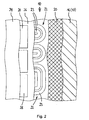
- This comprises a sleeve-like, ceramic support member 20, which also serves as electrical insulation, a wound thereon resistance wire 23 forms a Schuleiter Listel 22, the - as in Fig. 2 schematically indicated - depending on the desired temperature density can also be laid meandering.
- an outer cover layer 24 is applied, which covers the Schuleiter Listel 22 and the underlying support member 20 to the outside and electrically insulated.
- the arbitrarily deployable resistance wire 23 may be applied depending on the required power in different thickness and / or arrangement on the support member 20. As a result, a defined temperature distribution within the material tube 13 can be achieved if required.
- a temperature sensor 28 is provided from a PTC material whose resistance increases with increasing temperature ( Fig. 2 ).
- an electrically insulating contact layer 26 may be provided between other layers if necessary.
- the temperature sensor 28 may be made of resistance wire 29 as well as the heating conductor coil 22 (see Fig. 3 and 4 ).
- the resistance wire 29 forming the temperature sensor 28 expediently lies in the same plane as the resistance wire 23 forming the heating conductor spiral 22. They are jointly protected from the covering layer 24 to the outside. In this way, the height of the heater 10 is reduced to a minimum.
- the Fig. 3 . 4 and 5 show alternative possibilities for a design of Schuleiterdietaryl 22 and the conductors 29 for the temperature measurement.
- the covering layer 24 and / or the contact layer 26 are preferably applied by means of direct coating to the carrier element 20 in a material-locking manner and then baked under the particular material-specific baking conditions, so that a cohesive bond is formed which forms the heating device 10. Since the resistance wire 23 of the Edelleiter Listel 22 and the individual functional layers 24, 26 (optionally 28) have an extremely good adhesion to each other, the heater 10 holds a total of even extreme mechanical and / or thermal stresses durable.
- the heating device 10 is pushed from below onto the material pipe 13 with a predetermined play, which is selected such that the heating device 10 is not damaged in the heated operating state by the material pipe 13 expanding under the effect of heat, but always an optimum heat transfer between the carrier element 20 and the material tube 13 is ensured.
- a better heat transfer can be effected by an additional roughening the inside of the support element or the outside of the material tube.
- the inside of the carrier element or the outside of the material tube can be provided with a dark or black layer.
- This layer may consist of a black color, as used in the construction of radiant heating elements.
- a dark material may be used for the support tube, such as black alumina.
- the film and the thick-film screen printing technique for the application of the insulating layer or the cover layer, if necessary, the detonation coating or thermal coating methods.
- the thick-film screen printing technique using the round printing technology.
- the baking of the layers can be done individually or together.
- the electrical connections 23 'and 29' for the resistance wires 23, 29 of Schuetzmannl 22 and temperature sensor 28 may also be implemented in thick film technology or conventional, wherein the contacts required for this purpose are designed such that the power supply or information transmission can be made via pluggable cable connections.
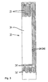
- Fig. 6 shows an alternative embodiment of a heating device 30 according to the invention in a developed and partially fanned-out representation.
- the heater 30 comprises a tubular or sleeve-like support member 32, which is substantially the support member 20 of the in the Fig. 1 and 2 shown heater 10 corresponds, but not made of ceramic but that is made of a metal or a metal alloy.
- an insulating layer or dielectric layer 34 is arranged on the carrier element 20, on which then the row Schuleitervvendel 22, possibly the contact layer 26, the temperature sensor 28 and the cover layer 24 are applied, as well as in Fig. 2
- the heating means 10. The application of the individual functional layer takes place in the same manner as in the heating device 10.
- a thick-film dielectric paste is applied in order to produce the dielectric layer 34 in the round-printing method.
- Their solids content can consist, for example, of a glass crystallizing in situ in the temperature range above 900 ° C. with the main components BaO, Al 2 O 3 and SiO 2 in the approximately molar composition BaO Al 2 O 3 4 SiO 2 .
- the dielectric layer 32 obtained after baking has a TEC of 6 ⁇ 10 -6 K -1 in the temperature range from 20 to 300 ° C.
Landscapes
- Engineering & Computer Science (AREA)
- Manufacturing & Machinery (AREA)
- Mechanical Engineering (AREA)
- Resistance Heating (AREA)
- Moulds For Moulding Plastics Or The Like (AREA)
Priority Applications (1)
| Application Number | Priority Date | Filing Date | Title |
|---|---|---|---|
| PL07801861T PL2094464T3 (pl) | 2006-10-18 | 2007-08-24 | Elektryczne urządzenie grzejne dla systemów gorącokanałowych oraz sposób jego wytwarzania |
Applications Claiming Priority (2)
| Application Number | Priority Date | Filing Date | Title |
|---|---|---|---|
| DE102006049669A DE102006049669A1 (de) | 2006-10-18 | 2006-10-18 | Elektrische Heizeinrichtung für Heißkanalsysteme |
| PCT/EP2007/007433 WO2008046465A1 (de) | 2006-10-18 | 2007-08-24 | Elektrische heizeinrichtung für heisskanalsysteme |
Publications (2)
| Publication Number | Publication Date |
|---|---|
| EP2094464A1 EP2094464A1 (de) | 2009-09-02 |
| EP2094464B1 true EP2094464B1 (de) | 2013-03-27 |
Family
ID=38654749
Family Applications (1)
| Application Number | Title | Priority Date | Filing Date |
|---|---|---|---|
| EP07801861A Active EP2094464B1 (de) | 2006-10-18 | 2007-08-24 | Elektrische heizeinrichtung für heisskanalsysteme und verfahren zu ihrer herstellung |
Country Status (12)
Families Citing this family (9)
| Publication number | Priority date | Publication date | Assignee | Title |
|---|---|---|---|---|
| DE202008015979U1 (de) * | 2008-12-03 | 2010-05-06 | Türk & Hillinger GmbH | Rohrförmiges Heizelement |
| DE102010049467B4 (de) | 2010-10-27 | 2022-08-04 | Günther Heisskanaltechnik Gmbh | Elektrische Anschlusseinrichtung für ein elektrisches Heizelement einer Heißkanaldüse und Heißkanaldüse |
| DE102012101400B4 (de) | 2012-02-22 | 2013-10-31 | Günther Heisskanaltechnik Gmbh | Heißkanaldüse mit einem elektrischen Heizelement |
| DE102012103839A1 (de) | 2012-05-02 | 2013-11-07 | Günther Heisskanaltechnik Gmbh | Heißkanaldüse mit Thermofühler |
| JP5702841B2 (ja) * | 2013-09-13 | 2015-04-15 | ファナック株式会社 | 成形材料温度調節ジャケットを有する成形機 |
| CN104029337B (zh) * | 2014-05-14 | 2017-01-04 | 苏州好特斯模具有限公司 | 一种防开裂主射嘴 |
| DE102015112748A1 (de) | 2015-08-03 | 2017-02-09 | Günther Heisskanaltechnik Gmbh | Heizelement für einen Strömungskanal oder ein Formnest und Spritzgießdüse mit einem solchen Heizelement |
| IT201800007339A1 (it) * | 2018-07-19 | 2020-01-19 | Riscaldatore elettrico per serbatoio | |
| CN111002538A (zh) * | 2019-11-26 | 2020-04-14 | 佛山市康铂特精密机械有限公司 | 一种具有精准加热功能的热流通道系统 |
Family Cites Families (14)
| Publication number | Priority date | Publication date | Assignee | Title |
|---|---|---|---|---|
| DE7922618U1 (de) * | 1979-08-08 | 1979-10-31 | Ibus Apparate-, Maschinenbau& Handelsgesellschaft Mbh, 7521 Forst | Heizpatrone |
| US4253011A (en) * | 1979-12-13 | 1981-02-24 | Tempco Electric Heater Corporation | Plastic injection molding system having a temperature controlled electric heater element |
| DE3141128C1 (de) * | 1981-10-16 | 1983-02-24 | Hotset Heizpatronen und Zubehör GmbH, 5880 Lüdenscheid | Verfahren zur Herstellung eines elektrischen Widerstands-Heizkörpers |
| US4558210A (en) * | 1984-08-03 | 1985-12-10 | Watlow Electric Manufacturing Company | Electric cast-metal heater |
| US4795337A (en) * | 1987-07-15 | 1989-01-03 | Gellert Jobst U | Coated injection molding nozzle |
| CA1267514A (en) * | 1987-07-15 | 1990-04-10 | Jobst Ulrich Gellert | Coated injection molding nozzle and method |
| JPH10272653A (ja) * | 1997-03-28 | 1998-10-13 | Sumitomo Heavy Ind Ltd | 射出成形機の射出ノズル |
| DE19941038A1 (de) * | 1999-08-28 | 2001-03-01 | Guenther Heiskanaltechnik Gmbh | Elektrische Heizung für Heißkanalsysteme und Verfahren zur Herstellung einer solchen Heizung |
| US6405785B1 (en) * | 2000-01-28 | 2002-06-18 | Mold-Masters Limited | Injection molding component with heating element and method of making |
| US6394784B1 (en) * | 2000-03-08 | 2002-05-28 | Mold-Masters Limited | Compact cartridge hot runner nozzle |
| JP3542121B2 (ja) * | 2001-01-30 | 2004-07-14 | 日精樹脂工業株式会社 | 粘度の温度依存性が高い樹脂の射出成形用ノズル |
| JP2006511035A (ja) * | 2002-03-13 | 2006-03-30 | ワトロウ エレクトリック マニュファクチュアリング カンパニー | ホット・ランナ加熱デバイス及びその製造方法 |
| DE20215960U1 (de) * | 2002-09-13 | 2003-01-16 | Türk & Hillinger GmbH, 78532 Tuttlingen | Elektrische Heizpatrone für zylindrische Körper |
| DE10313253B4 (de) * | 2003-03-25 | 2005-06-23 | Hotset Heizpatronen U. Zubehör Gmbh | Rohrförmiges elektrisches Heizelement |
-
2006
- 2006-10-18 DE DE102006049669A patent/DE102006049669A1/de not_active Ceased
-
2007
- 2007-08-24 JP JP2009532688A patent/JP2010506754A/ja not_active Withdrawn
- 2007-08-24 BR BRPI0715005-9A patent/BRPI0715005A2/pt not_active Application Discontinuation
- 2007-08-24 CN CNA2007800387807A patent/CN101528439A/zh active Pending
- 2007-08-24 CA CA002666915A patent/CA2666915A1/en not_active Abandoned
- 2007-08-24 PL PL07801861T patent/PL2094464T3/pl unknown
- 2007-08-24 WO PCT/EP2007/007433 patent/WO2008046465A1/de active Application Filing
- 2007-08-24 MX MX2009003209A patent/MX2009003209A/es not_active Application Discontinuation
- 2007-08-24 TW TW096131428A patent/TW200904231A/zh unknown
- 2007-08-24 US US12/311,904 patent/US20100068331A1/en not_active Abandoned
- 2007-08-24 KR KR1020097007855A patent/KR20090079201A/ko not_active Withdrawn
- 2007-08-24 EP EP07801861A patent/EP2094464B1/de active Active
Also Published As
| Publication number | Publication date |
|---|---|
| TW200904231A (en) | 2009-01-16 |
| EP2094464A1 (de) | 2009-09-02 |
| CN101528439A (zh) | 2009-09-09 |
| WO2008046465A1 (de) | 2008-04-24 |
| KR20090079201A (ko) | 2009-07-21 |
| BRPI0715005A2 (pt) | 2013-05-28 |
| US20100068331A1 (en) | 2010-03-18 |
| MX2009003209A (es) | 2009-04-07 |
| PL2094464T3 (pl) | 2013-10-31 |
| DE102006049669A1 (de) | 2008-04-24 |
| JP2010506754A (ja) | 2010-03-04 |
| CA2666915A1 (en) | 2008-04-24 |
Similar Documents
| Publication | Publication Date | Title |
|---|---|---|
| EP2094464B1 (de) | Elektrische heizeinrichtung für heisskanalsysteme und verfahren zu ihrer herstellung | |
| EP2080415B1 (de) | Elektrische heizeinrichtung für heisskanalsysteme | |
| EP1206900B1 (de) | Elektrische heizung für heisskanalsysteme und verfahren zur herstellung einer solchen heizung | |
| DE60106579T2 (de) | Kompakte rohrheizkörperheisskanaldüse und verfahren zu ihrer herstellung | |
| EP2793008B1 (de) | Kalibrator zur Kalibrierung von Temperaturmesseinrichtungen | |
| WO2008006689A1 (de) | Resistive supraleitende strombegrenzereinrichtung mit bifilarer spulenwicklung aus hts-bandleitern und windungsabstandshalter | |
| DE102013111442A1 (de) | Mehrfachbeschichteter anodisierter Draht und Verfahren zu seiner Herstellung | |
| DE19510989A1 (de) | Bauteilkombination für elektrische Heizplatten, Zündeinrichtungen, Temperatursensoren o. dgl. | |
| DE3031751A1 (de) | Verfahren zur herstellung elektrotechnischer bauteile und nach diesem verfahren hergestellter schiebe- oder drehwiderstand | |
| DE102007010395A1 (de) | Verfahren zur Herstellung einer elektrischen Heizung und/oder eines Temperaturfühlers für Heißkanalsysteme | |
| DE19600069C2 (de) | Elektrischer PTC-Heizkörper | |
| EP1550353B1 (de) | Verbundkörper und verfahren zu dessen herstellung | |
| EP2253181B1 (de) | Anschlussstift und elektrischer anschluss | |
| DE102008015376B4 (de) | Elektrische Verbindung | |
| AT514082B1 (de) | Strukturbauelement mit elektrischem Heizelement, Heizvorrichtung mit einem solchen Strukturbauelement und Verfahren zur Herstellung eines solchen Strukturbauelements | |
| EP0670209B1 (de) | Heizeinrichtung, insbesondere zum Einsatz in Spritzgiessformen zum Verarbeiten thermoplastischer Materialien | |
| DE1141737B (de) | Verfahren zur Herstellung von flachen elektrischen Heizelementen fuer hohe Temperaturen bis zu 600°C und nach dem Verfahren hergestelltes elektrisches Heizelement | |
| DE102022205495A1 (de) | Heizeinrichtung und Verfahren zur Herstellung einer solchen Heizeinrichtung | |
| EP2487022A2 (de) | Heizelement für Heißkanaldüsen und Verfahren zu dessen Herstellung | |
| EP3317888B1 (de) | Verfahren zur herstellung eines elektrischen bauelements | |
| DE102012105467A1 (de) | Verfahren zur Herstellung eines Werkzeuges | |
| DE102006053001A1 (de) | Heizvorrichtung zur Beheizung von Werkstücken | |
| DE2112595A1 (de) | Verfahren zur Herstellung eines aufloetbaren Temperaturmesswiderstandes und aufleotbare Temperaturmesswiderstaende | |
| DE102004012364A1 (de) | Keramische Glühstiftkerze mit in Glühstift integriertem Drucksensor | |
| DE2622435A1 (de) | Keramischer elektrischer einbett- heizwiderstand und verfahren zu seiner herstellung |
Legal Events
| Date | Code | Title | Description |
|---|---|---|---|
| PUAI | Public reference made under article 153(3) epc to a published international application that has entered the european phase |
Free format text: ORIGINAL CODE: 0009012 |
|
| 17P | Request for examination filed |
Effective date: 20090514 |
|
| AK | Designated contracting states |
Kind code of ref document: A1 Designated state(s): AT BE BG CH CY CZ DE DK EE ES FI FR GB GR HU IE IS IT LI LT LU LV MC MT NL PL PT RO SE SI SK TR |
|
| 17Q | First examination report despatched |
Effective date: 20090916 |
|
| DAX | Request for extension of the european patent (deleted) | ||
| GRAP | Despatch of communication of intention to grant a patent |
Free format text: ORIGINAL CODE: EPIDOSNIGR1 |
|
| GRAS | Grant fee paid |
Free format text: ORIGINAL CODE: EPIDOSNIGR3 |
|
| GRAA | (expected) grant |
Free format text: ORIGINAL CODE: 0009210 |
|
| AK | Designated contracting states |
Kind code of ref document: B1 Designated state(s): AT BE BG CH CY CZ DE DK EE ES FI FR GB GR HU IE IS IT LI LT LU LV MC MT NL PL PT RO SE SI SK TR |
|
| REG | Reference to a national code |
Ref country code: GB Ref legal event code: FG4D Free format text: NOT ENGLISH |
|
| REG | Reference to a national code |
Ref country code: CH Ref legal event code: EP |
|
| REG | Reference to a national code |
Ref country code: AT Ref legal event code: REF Ref document number: 603081 Country of ref document: AT Kind code of ref document: T Effective date: 20130415 |
|
| REG | Reference to a national code |
Ref country code: IE Ref legal event code: FG4D Free format text: LANGUAGE OF EP DOCUMENT: GERMAN |
|
| REG | Reference to a national code |
Ref country code: DE Ref legal event code: R096 Ref document number: 502007011525 Country of ref document: DE Effective date: 20130529 |
|
| PG25 | Lapsed in a contracting state [announced via postgrant information from national office to epo] |
Ref country code: SE Free format text: LAPSE BECAUSE OF FAILURE TO SUBMIT A TRANSLATION OF THE DESCRIPTION OR TO PAY THE FEE WITHIN THE PRESCRIBED TIME-LIMIT Effective date: 20130327 Ref country code: LT Free format text: LAPSE BECAUSE OF FAILURE TO SUBMIT A TRANSLATION OF THE DESCRIPTION OR TO PAY THE FEE WITHIN THE PRESCRIBED TIME-LIMIT Effective date: 20130327 Ref country code: BG Free format text: LAPSE BECAUSE OF FAILURE TO SUBMIT A TRANSLATION OF THE DESCRIPTION OR TO PAY THE FEE WITHIN THE PRESCRIBED TIME-LIMIT Effective date: 20130627 |
|
| REG | Reference to a national code |
Ref country code: NL Ref legal event code: T3 |
|
| REG | Reference to a national code |
Ref country code: LT Ref legal event code: MG4D |
|
| PG25 | Lapsed in a contracting state [announced via postgrant information from national office to epo] |
Ref country code: GR Free format text: LAPSE BECAUSE OF FAILURE TO SUBMIT A TRANSLATION OF THE DESCRIPTION OR TO PAY THE FEE WITHIN THE PRESCRIBED TIME-LIMIT Effective date: 20130628 Ref country code: SI Free format text: LAPSE BECAUSE OF FAILURE TO SUBMIT A TRANSLATION OF THE DESCRIPTION OR TO PAY THE FEE WITHIN THE PRESCRIBED TIME-LIMIT Effective date: 20130327 Ref country code: LV Free format text: LAPSE BECAUSE OF FAILURE TO SUBMIT A TRANSLATION OF THE DESCRIPTION OR TO PAY THE FEE WITHIN THE PRESCRIBED TIME-LIMIT Effective date: 20130327 Ref country code: FI Free format text: LAPSE BECAUSE OF FAILURE TO SUBMIT A TRANSLATION OF THE DESCRIPTION OR TO PAY THE FEE WITHIN THE PRESCRIBED TIME-LIMIT Effective date: 20130327 |
|
| REG | Reference to a national code |
Ref country code: SK Ref legal event code: T3 Ref document number: E 14332 Country of ref document: SK |
|
| PG25 | Lapsed in a contracting state [announced via postgrant information from national office to epo] |
Ref country code: IS Free format text: LAPSE BECAUSE OF FAILURE TO SUBMIT A TRANSLATION OF THE DESCRIPTION OR TO PAY THE FEE WITHIN THE PRESCRIBED TIME-LIMIT Effective date: 20130727 Ref country code: PT Free format text: LAPSE BECAUSE OF FAILURE TO SUBMIT A TRANSLATION OF THE DESCRIPTION OR TO PAY THE FEE WITHIN THE PRESCRIBED TIME-LIMIT Effective date: 20130729 Ref country code: RO Free format text: LAPSE BECAUSE OF FAILURE TO SUBMIT A TRANSLATION OF THE DESCRIPTION OR TO PAY THE FEE WITHIN THE PRESCRIBED TIME-LIMIT Effective date: 20130327 Ref country code: EE Free format text: LAPSE BECAUSE OF FAILURE TO SUBMIT A TRANSLATION OF THE DESCRIPTION OR TO PAY THE FEE WITHIN THE PRESCRIBED TIME-LIMIT Effective date: 20130327 Ref country code: ES Free format text: LAPSE BECAUSE OF FAILURE TO SUBMIT A TRANSLATION OF THE DESCRIPTION OR TO PAY THE FEE WITHIN THE PRESCRIBED TIME-LIMIT Effective date: 20130708 |
|
| REG | Reference to a national code |
Ref country code: PL Ref legal event code: T3 |
|
| PG25 | Lapsed in a contracting state [announced via postgrant information from national office to epo] |
Ref country code: CY Free format text: LAPSE BECAUSE OF FAILURE TO SUBMIT A TRANSLATION OF THE DESCRIPTION OR TO PAY THE FEE WITHIN THE PRESCRIBED TIME-LIMIT Effective date: 20130327 |
|
| PG25 | Lapsed in a contracting state [announced via postgrant information from national office to epo] |
Ref country code: DK Free format text: LAPSE BECAUSE OF FAILURE TO SUBMIT A TRANSLATION OF THE DESCRIPTION OR TO PAY THE FEE WITHIN THE PRESCRIBED TIME-LIMIT Effective date: 20130327 |
|
| PLBE | No opposition filed within time limit |
Free format text: ORIGINAL CODE: 0009261 |
|
| STAA | Information on the status of an ep patent application or granted ep patent |
Free format text: STATUS: NO OPPOSITION FILED WITHIN TIME LIMIT |
|
| BERE | Be: lapsed |
Owner name: GUNTHER HEISSKANALTECHNIK G.M.B.H. Effective date: 20130831 |
|
| 26N | No opposition filed |
Effective date: 20140103 |
|
| REG | Reference to a national code |
Ref country code: CH Ref legal event code: PL |
|
| REG | Reference to a national code |
Ref country code: DE Ref legal event code: R097 Ref document number: 502007011525 Country of ref document: DE Effective date: 20140103 |
|
| PG25 | Lapsed in a contracting state [announced via postgrant information from national office to epo] |
Ref country code: SK Free format text: LAPSE BECAUSE OF NON-PAYMENT OF DUE FEES Effective date: 20130824 Ref country code: CZ Free format text: LAPSE BECAUSE OF NON-PAYMENT OF DUE FEES Effective date: 20130824 Ref country code: CH Free format text: LAPSE BECAUSE OF NON-PAYMENT OF DUE FEES Effective date: 20130831 Ref country code: MC Free format text: LAPSE BECAUSE OF FAILURE TO SUBMIT A TRANSLATION OF THE DESCRIPTION OR TO PAY THE FEE WITHIN THE PRESCRIBED TIME-LIMIT Effective date: 20130327 Ref country code: LI Free format text: LAPSE BECAUSE OF NON-PAYMENT OF DUE FEES Effective date: 20130831 |
|
| REG | Reference to a national code |
Ref country code: SK Ref legal event code: MM4A Ref document number: E 14332 Country of ref document: SK Effective date: 20130824 |
|
| REG | Reference to a national code |
Ref country code: IE Ref legal event code: MM4A |
|
| PG25 | Lapsed in a contracting state [announced via postgrant information from national office to epo] |
Ref country code: BE Free format text: LAPSE BECAUSE OF NON-PAYMENT OF DUE FEES Effective date: 20130831 |
|
| PG25 | Lapsed in a contracting state [announced via postgrant information from national office to epo] |
Ref country code: IE Free format text: LAPSE BECAUSE OF NON-PAYMENT OF DUE FEES Effective date: 20130824 |
|
| REG | Reference to a national code |
Ref country code: AT Ref legal event code: MM01 Ref document number: 603081 Country of ref document: AT Kind code of ref document: T Effective date: 20130824 |
|
| PG25 | Lapsed in a contracting state [announced via postgrant information from national office to epo] |
Ref country code: AT Free format text: LAPSE BECAUSE OF NON-PAYMENT OF DUE FEES Effective date: 20130824 Ref country code: PL Free format text: LAPSE BECAUSE OF NON-PAYMENT OF DUE FEES Effective date: 20130824 |
|
| REG | Reference to a national code |
Ref country code: PL Ref legal event code: LAPE |
|
| PG25 | Lapsed in a contracting state [announced via postgrant information from national office to epo] |
Ref country code: MT Free format text: LAPSE BECAUSE OF FAILURE TO SUBMIT A TRANSLATION OF THE DESCRIPTION OR TO PAY THE FEE WITHIN THE PRESCRIBED TIME-LIMIT Effective date: 20130327 |
|
| PG25 | Lapsed in a contracting state [announced via postgrant information from national office to epo] |
Ref country code: HU Free format text: LAPSE BECAUSE OF FAILURE TO SUBMIT A TRANSLATION OF THE DESCRIPTION OR TO PAY THE FEE WITHIN THE PRESCRIBED TIME-LIMIT; INVALID AB INITIO Effective date: 20070824 Ref country code: LU Free format text: LAPSE BECAUSE OF NON-PAYMENT OF DUE FEES Effective date: 20130824 |
|
| REG | Reference to a national code |
Ref country code: FR Ref legal event code: PLFP Year of fee payment: 10 |
|
| REG | Reference to a national code |
Ref country code: DE Ref legal event code: R082 Ref document number: 502007011525 Country of ref document: DE Representative=s name: PATENTANWAELTE OLBRICHT, BUCHHOLD, KEULERTZ PA, DE |
|
| REG | Reference to a national code |
Ref country code: FR Ref legal event code: PLFP Year of fee payment: 11 |
|
| REG | Reference to a national code |
Ref country code: FR Ref legal event code: PLFP Year of fee payment: 12 |
|
| PGFP | Annual fee paid to national office [announced via postgrant information from national office to epo] |
Ref country code: TR Payment date: 20200819 Year of fee payment: 14 |
|
| PGFP | Annual fee paid to national office [announced via postgrant information from national office to epo] |
Ref country code: NL Payment date: 20240821 Year of fee payment: 18 |
|
| PG25 | Lapsed in a contracting state [announced via postgrant information from national office to epo] |
Ref country code: TR Free format text: LAPSE BECAUSE OF NON-PAYMENT OF DUE FEES Effective date: 20210824 |
|
| PGFP | Annual fee paid to national office [announced via postgrant information from national office to epo] |
Ref country code: DE Payment date: 20240831 Year of fee payment: 18 |
|
| PGFP | Annual fee paid to national office [announced via postgrant information from national office to epo] |
Ref country code: GB Payment date: 20240823 Year of fee payment: 18 |
|
| PGFP | Annual fee paid to national office [announced via postgrant information from national office to epo] |
Ref country code: FR Payment date: 20240828 Year of fee payment: 18 |
|
| PGFP | Annual fee paid to national office [announced via postgrant information from national office to epo] |
Ref country code: IT Payment date: 20240827 Year of fee payment: 18 |