EP2094174B1 - Verfahren und maschine zur handhabung giftiger stoffe - Google Patents
Verfahren und maschine zur handhabung giftiger stoffe Download PDFInfo
- Publication number
- EP2094174B1 EP2094174B1 EP07848922A EP07848922A EP2094174B1 EP 2094174 B1 EP2094174 B1 EP 2094174B1 EP 07848922 A EP07848922 A EP 07848922A EP 07848922 A EP07848922 A EP 07848922A EP 2094174 B1 EP2094174 B1 EP 2094174B1
- Authority
- EP
- European Patent Office
- Prior art keywords
- needle
- pixels
- image
- ordinates
- determining
- Prior art date
- Legal status (The legal status is an assumption and is not a legal conclusion. Google has not performed a legal analysis and makes no representation as to the accuracy of the status listed.)
- Active
Links
Images


Classifications
-
- G—PHYSICS
- G06—COMPUTING OR CALCULATING; COUNTING
- G06T—IMAGE DATA PROCESSING OR GENERATION, IN GENERAL
- G06T1/00—General purpose image data processing
- G06T1/0014—Image feed-back for automatic industrial control, e.g. robot with camera
-
- A—HUMAN NECESSITIES
- A61—MEDICAL OR VETERINARY SCIENCE; HYGIENE
- A61B—DIAGNOSIS; SURGERY; IDENTIFICATION
- A61B17/00—Surgical instruments, devices or methods
- A61B17/34—Trocars; Puncturing needles
-
- A—HUMAN NECESSITIES
- A61—MEDICAL OR VETERINARY SCIENCE; HYGIENE
- A61M—DEVICES FOR INTRODUCING MEDIA INTO, OR ONTO, THE BODY; DEVICES FOR TRANSDUCING BODY MEDIA OR FOR TAKING MEDIA FROM THE BODY; DEVICES FOR PRODUCING OR ENDING SLEEP OR STUPOR
- A61M5/00—Devices for bringing media into the body in a subcutaneous, intra-vascular or intramuscular way; Accessories therefor, e.g. filling or cleaning devices, arm-rests
- A61M5/178—Syringes
- A61M5/20—Automatic syringes, e.g. with automatically actuated piston rod, with automatic needle injection, filling automatically
-
- G—PHYSICS
- G06—COMPUTING OR CALCULATING; COUNTING
- G06T—IMAGE DATA PROCESSING OR GENERATION, IN GENERAL
- G06T1/00—General purpose image data processing
-
- Y—GENERAL TAGGING OF NEW TECHNOLOGICAL DEVELOPMENTS; GENERAL TAGGING OF CROSS-SECTIONAL TECHNOLOGIES SPANNING OVER SEVERAL SECTIONS OF THE IPC; TECHNICAL SUBJECTS COVERED BY FORMER USPC CROSS-REFERENCE ART COLLECTIONS [XRACs] AND DIGESTS
- Y10—TECHNICAL SUBJECTS COVERED BY FORMER USPC
- Y10T—TECHNICAL SUBJECTS COVERED BY FORMER US CLASSIFICATION
- Y10T436/00—Chemistry: analytical and immunological testing
- Y10T436/25—Chemistry: analytical and immunological testing including sample preparation
- Y10T436/2575—Volumetric liquid transfer
Definitions
- the present invention relates to a method and to a machine for manipulating toxic substances.
- the present invention finds advantageous, but non-exclusive application, in a machine for automatic manipulation of toxic substances used for automatic preparation of cytostatic drugs, to which the following description will make explicit reference, without this implying any loss in generality.
- a magazine for containers such as sacs, flasks and the like, each provided with a mouth closed by a respective cap made of perforable material and containing substances necessary for the preparation of drugs
- a dosage station present in which is at least one seat designed to withhold a corresponding syringe of a commercial type
- an anthropomorphic robot provided with a gripping head for picking up a container from the magazine, transferring it to the dosage station at a point corresponding to a syringe, and approaching it to the needle of the syringe in such a way that the needle, by perforating the cap, penetrates into the container to be able to inject therein or draw therefrom a substance.
- an optical sensor of the photocell type for facilitating axial alignment of the mouth with the needle of the syringe.
- said positional correlation is performed by using at least one camera located on the robot arm and subsequently taking two images at two spaced apart positions.
- the two positions at which said images are taken should be as much spaced apart as possible, i.e. at two extreme positions the robotic arm can be moved to.
- the aim of the present invention is to provide a method and a machine for automatic manipulation of toxic substances in order to prepare cytostatic drugs, as well as a computer program product implementing said method, said method and machine being free from the drawbacks described above and, at the same time, being easy and inexpensive to provide.
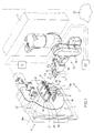
- a machine for manipulating toxic substances comprising: a magazine 2 (schematically illustrated by a parallelepiped) for containers 3, such as sacs, flasks, and the like, for toxic and non-toxic substances, necessary for the preparation of drugs, each of said containers being provided with a mouth 4 having an axis 4a and closed by a respective cap 5 made of perforable material; a dosage station 6, set in which is a dosage assembly 7 provided with three seats 8 designed to withhold as many syringes 9 of a commercial type of various format, i.e., of the type comprising a body 10 having a cylindrical shape, a needle.
- a gripping head 14 comprising a gripper member 15 designed to grip the containers 3, and an articulated arm 16 with six degrees of freedom, designed to support the head 14 to be able to transfer a container 3 from the magazine 2 to the dosage station 6 at a point corresponding to a syringe 9 and approach the container 3 itself to the needle 11 of said syringe 9 in such a way that the needle 11, by perforating the cap 5, penetrates into the container 3.
- the machine 1 is, moreover, provided with a control unit 17 for controlling actuation of the robot 13, of the dosage assembly 7, and of members (not illustrated) for moving the magazine 2.
- the dosage assembly 7 and the robot 13 are housed in a sterile compartment (not illustrated), communicating with the magazine 2, to prevent germs or micro-organisms from contaminating the drugs during their preparation.
- the dosage assembly 7 comprises a platform 18 rotating about a horizontal axis 18a, there being mounted on said platform 18 three seats 8 for syringes.
- Each seat 8 comprises a gripping element 19 fixed with respect to the platform 18 for withholding the body 10 of the syringe 9 with a longitudinal axis 9a of the syringe 9 substantially vertical, and an actuation element 20 for extracting the plunger 12 so as to draw an amount of substance into the syringe 9 or to press the plunger 12 in order to inject an amount of substance into the container 3.
- the actuation elements 20 are rigidly connected to one another by a bar 21 designed to move vertically along a rectilinear guide 22 made on the platform 18.
- Rotation of the platform 18 enables change of orientation of the syringes 9 between a position where the substance is drawn in, in which the tip of the needle 11 faces upwards, and a position (illustrated in Figure 1 ) of injection of the substance into the container, in which the tip of the needle 11 faces downwards.
- the machine moreover comprises: a fixed-focus black-and-white analogical telecamera 23, which is provided with a video-composite output (not illustrated) and is mounted in a fixed way on the head 14; and a computer 24, for example of the PC-architecture type, connected to a hospital computer system 25 for exchanging data on the preparation of drugs with the telecamera 23 for acquiring the images detected thereby and with the control unit 17 for controlling the members of the machine 1 that are described above.
- a fixed-focus black-and-white analogical telecamera 23 which is provided with a video-composite output (not illustrated) and is mounted in a fixed way on the head 14
- a computer 24 for example of the PC-architecture type, connected to a hospital computer system 25 for exchanging data on the preparation of drugs with the telecamera 23 for acquiring the images detected thereby and with the control unit 17 for controlling the members of the machine 1 that are described above.
- the gripper member 15 of the head 14 comprises two jaws 26 mobile along an axis of sliding 26a with a movement of mutual approach and recession for gripping and, respectively, releasing the container 3.
- the telecamera 23 is mounted on the head 14 with an optical axis 23a of its own perpendicular to a plane on which the axis of sliding 26a lies.
- the computer 24 comprises: an image-acquisition card 27, which is of the type known as "framegrabber" and has a video-composite input (not illustrated) connected to the video-composite output of the telecamera 23; an interface unit 28, for example a touch screen, to enable an operator to interact with the machine 1; a processing unit 29, which is designed to process the data on the drugs and the images acquired in order to determine the commands to be sent to the control unit 17; and a communication unit 30 connected to the control unit 17 and to the hospital computer system 25.
- an image-acquisition card 27 which is of the type known as "framegrabber" and has a video-composite input (not illustrated) connected to the video-composite output of the telecamera 23
- an interface unit 28 for example a touch screen, to enable an operator to interact with the machine 1
- a processing unit 29, which is designed to process the data on the drugs and the images acquired in order to determine the commands to be sent to the control unit 17
- a communication unit 30 connected to the control unit 17 and
- Loaded into the processing unit 29 is a control program designed for implementing, when run on the processing unit 29 itself, the method for manipulating toxic substances according to the present invention.
- the method envisages control of the arm 16 of the robot 13 for picking up the container 3 from the magazine 2 and transferring it into the dosage station 6, and, substantially at the same time, the platform 18 is rotated to bring the syringe 9 into the injection position, i.e., with the needle 11 facing downwards.
- the arm 16 positions the container 3 underneath the needle 11 with the mouth 4 facing upwards. It axially aligns the mouth 4 of the container 3 with the needle 11, i.e., it brings the axis 4a of the mouth 4 substantially to coincide with an axis of the needle 11. Then, it raises the container 3 longitudinally towards the needle 11 in such a way that a considerable part of the needle 11, after perforating the cap 5, penetrates into the container 3.
- the actuation element 20 is brought down in order to press the plunger 12 into the body 10 of the syringe 9 just enough to inject the desired amount of substance into the container 3.
- the step of axial alignment of the mouth 4 of the container 3 with the needle 11 envisages: acquiring two images of the needle 11 from two respective distinct observation points; processing said images to determine the position of the tip of the needle 11 and the inclination of the needle 11, i.e., the inclination of an axis of the needle 11 with respect to the axis 9a of the syringe 9; and actuating the arm 16 of the robot 13 so as to correct the position of the head 14, and hence of the container 3, according to the position of the tip of the needle 11 and of the inclination of the needle 11.
- processing of the two images basically consists in determining, for each of the images, the spatial co-ordinates of two points along the needle 11 and in calculating the position of the tip of the needle 11 and the inclination of the needle 11 as a function of said co-ordinates on the basis of the known principle of optical triangulation.
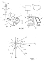
- FT and FS are two distinct directions of framing orthogonal to the axis Z. Defined on the directions of framing FT and FS are two respective observation points OT and OS set substantially at the same distance from the point P.
- the arm 16 of the robot 13 displaces and rotates, about the axis Z, the head 14 so as to position the telecamera 23 first in the observation point OT with the optical axis 23a parallel to the direction of framing FT and then in the observation point OS with the optical axis parallel to the direction of framing FS.
- the directions of framing FT and FS form between them an acute angle.
- the directions of framing FT and FS form with the axis Y two respective angles a and ⁇ and are orthogonal to two respective planes of framing, each defined by the axis Z and by a respective axis t, s orthogonal to the axis Z.
- the value of the angles a and ⁇ is such that their sum (a+ ⁇ ) is less than 90°, and in particular less than or equal to 40°.
- the co-ordinates of the point P with respect to the cartesian axes X and Y are designated by Xp and Yp, and the co-ordinates of the point P with respect to the axes t and s are designated by tp and sp.
- Figure 4 illustrates a flowchart that describes processing of the two images acquired from the respective observation points OT and OS in order to determine the position of the tip of the needle 11 and the inclination of the needle 11.
- the subsequent Figures 5, 6 and 7 are schematic illustrations of some steps of said processing.
- Image processing is implemented in a portion of said control program written in a programming language known as LabVIEW ® and compiled, in the Microsoft ® Windows ® environment, as data-link library (DLL).
- DLL data-link library
- the image of the needle 11 is first acquired in a digital format (block 100), after which an area of interest 31 of the image ( Figure 5 ), i.e., a rectangular portion of the image, is defined, within which area of interest 31 the needle 11 will be sought (block 101), and an image-contrast threshold is adjusted to a minimum value, beyond which it is possible to detect the needle (block 102).
- the area of interest 31 is defined by carrying out filtering operations of a known type on the image of the needle 11.
- IMAQ Edge Tool a function, known as "IMAQ Edge Tool”
- IMAQ Vision a library, known as IMAQ Vision
- a check is made to assess whether said edge is compatible with the tip of the needle 11, i.e., whether said edge falls within a compatibility area 32 ( Figure 5 ) defined as a given rectangular portion of the area of interest 31 in which the tip of the needle 11 is expected to be located (block 106).
- the edge found is compatible (output YES from block 106)
- the co-ordinates of said edge are extracted from the image, said edge corresponding to the first point P1 sought and defining the tip of the needle 11 ( Figure 5 ) (block 110); otherwise, the contrast threshold (block 111) is increased by a given amount in order to adapt the search for the needle 11 to the quality of the image and the examination of the area of interest is repeated starting from the first row (block 103).
- the maximum value of the contrast threshold is reached without any edge having been found in the compatibility area (output YES from block 112), then an error message is produced of the type "needle in an unexpected position" (block 109).
- the second point P2 through which the needle 11 passes is determined.
- examination passes to a row that is distant from the row of the point P1 by a pre-set number OFFSET of rows ( Figure 6 ) (block 113), the contrast threshold is adjusted to a maximum value (block 114), and the scan is made of the row in question to seek edge using the "IMAQ Edge Tool" function mentioned above (block 115).
- a check is made to assess whether the distance between a first edge EF and a last edge EL found in the row in question is compatible with the transverse dimensions of the needle 11, i..e., if said distance is equal, within a given tolerance, to the diameter of the needle 11 (block 117).
- the contrast threshold is reduced by a given amount (block 118) and the scan of the row in question is repeated (block 115).
- the point P2 is calculated as intermediate point between the points identified by the edges EF and EL ( Figure 7 ) (block 120).
- the co-ordinates of the points P1 and P2 supplied by blocks 110 and 120 are expressed in pixels.
- the determination of the point P2 is followed by an operation of transformation of the co-ordinates of the points P1 and P2 from pixels to millimetres (block 121) by applying transformation coefficients obtained during a step of calibration that will be described hereinafter.
- the algorithm defined by blocks 100 to 121 is repeated for each of the two images acquired (block 122).
- obtained from the image acquired from the observation point OT are the co-ordinates of the points P1 and P2 with respect to the axes t and Z
- obtained from the image acquired from observation point OS are the co-ordinates with respect to the axes s and Z.
- the co-ordinates t1, s1, Z1 for the point P1 and the co-ordinates t2, s2, Z2 for the point P2 are obtained.
- expressions (1) and (2) are applied to obtain the cartesian co-ordinates X1 and Y1 as a function of the co-ordinates s1 and t1, and the cartesian co-ordinates X2 and Y2 as a function of the co-ordinates s2 and t2 (block 123), and expressions (3) and (4) are applied to calculate the inclination of the needle 11 as a function of the co-ordinates of the two points P1 and P2 (block 124).
- the calibration step mentioned previously it is performed prior to any preparation of drugs and envisages acquiring three further images of the needle 11 of a syringe 9 fixed in a standard position, for example, housed in a corresponding seat 8 with the tip of the needle 11 facing downwards.
- a first one of said further images is recorded after positioning, via the arm 16 of the robot 13, the telecamera 23 in one of the observation points, for example in the point OT, with the optical axis 23a parallel to the corresponding direction of framing FT.
- a second image and a third image are acquired after displacing, once again by means of the arm 16, the telecamera 23 a first time only along the axis t and a second time only along the axis Z by respective known amounts expressed in millimetres, maintaining the distance from the axis 9a substantially constant.
- FIG 8 which shows a new flowchart, in which, however, some blocks that correspond to the ones already described are designated by the same numbers as those used in Figure 4 , and again illustrated in Figures 9 to 11 , where elements corresponding to the ones described are designated by the same reference numbers as those used in Figures 5 to 7 , respectively, the points P1 and P2 sought are determined by processing in a different way the area of interest 31 of each digital image of the needle 11.
- Each digital image of the needle 11 is constituted by a matrix of pixels obtained according to known digital acquisition techniques. Consequently, the corresponding area of interest 31 is constituted by a sub-matrix of said matrix of pixels.
- Figure 9 illustrates, in a simplified way, a portion of image 33 of the area of interest 31, in which the tip of the needle 11 may be noted.
- the portion of image 33 is shown divided into a plurality of pixels. Those corresponding to the tip of the needle 11 are represented with an oblique line.
- the position of a generic pixel PX in the compatibility area 32 is identified by a pair of co-ordinates in pixels, the first one of which is expressed with respect to the axis Z and is designated by r and the second one of which is expressed with respect to the axis t, s and is designated by c.
- the co-ordinate r identifies a row of pixels
- the co-ordinate c identifies a column of pixels.
- a pixel intensity threshold is set to a pre-set value (block 200).
- the value of the intensity threshold is adjustable by the operator.
- the co-ordinates c, r of the pixel PXF are stored in a corresponding position of a first pixel vector VF, and the co-ordinates of the pixel PXL are stored in a corresponding position of a second pixel vector VL (block 203).
- the two pixel vectors VF and VL are implemented in an internal memory (not illustrated) of the processing unit 29 ( Figure 2 ).
- a cycle of linearization is carried out to determine, according to the two vectors VF and VL, two straight lines that enable precise identification of the position of the tip of the needle 11 and the inclination of the needle 11.
- the cycle envisages, first of all, calculation of a first straight line, designated by LF in Figure 11 , on the basis of a linear interpolation of the co-ordinates stored in the vector VF, and a second straight line, designated by LL in Figure 11 , on the basis of a linear interpolation of the co-ordinates stored in the other vector VL (block 207).
- a check is made to verify whether the calculation of the straight lines LF and LL has been made correctly on the basis of whether two conditions are met or not (block 208), a first one of which is made on the angular coefficients MF and ML, i.e., on whether the absolute value of their difference is smaller than a pre-set limit difference DM, MF - ML ⁇ DM , and the second one of which is made on the offsets QF and QL, i.e., on whether their difference is comprised between a pre-set minimum difference DQmin and a pre-set maximum difference Dqmax, DQmin ⁇ QF - QL ⁇ DQmax .
- the limit difference DM is preferably equal to 0.2.
- the minimum difference is preferably equal to 10, and the maximum difference DQmax is preferably equal to 200 pixels.
- the pairs of pixels PXF, PXL that fall outside a shape of the tip of the needle 11 defined by a portion of plane comprised between the straight lines LF and LL and that are distant, along the respective rows of pixels, from the straight lines LF and LL themselves by a pre-set amount (block 209).
- the pairs of pixels PXF, PXL to be eliminated must satisfy at least one of the following two conditions.
- a first one of said conditions is that the co-ordinate c of the pixel PXF, designated by c_PXF, increased by a pre-set deviation S is smaller than a co-ordinate c_LF given by Equation (5) corresponding to the co-ordinate r of the pixel PXF itself, i.e., c_PXF_ + S ⁇ c_LF ,
- PXLe is one of the pairs of pixels to eliminated.
- the first point P1 sought is determined as a function of a pair of pixels PXF1, PXL1, which, from among all the pairs of pixels PXF, PXL stored in the vectors VF and VL, has the co-ordinate r of lowest value, hereinafter designated by r1, and that remains substantially within the shape defined by the straight lines LF and FF (block 212).
- the pair of pixels PXF1, PXL1 selected must satisfy two further conditions: the distance between the corresponding co-ordinates c_PXF and c_PXL is less than a pre-set distance DPX, namely c_PXF - c_PXL ⁇ DPX ; and a mean value of the co-ordinates c_PXF and c_PXL, hereinafter designated by c1, is comprised, but for a tolerance TPX, between the straight lines LF and LL corresponding to the co-ordinates r1, namely c_LF ⁇ c ⁇ 1 - TPX ⁇ c_LL .
- the co-ordinates in pixels c1 and r1 thus determined identify the point P1 on the plane of the image acquired.
- a third straight line LN is calculated ( Figure 11 ) as vector sum of the directions identified by the two straight lines LF and LL (block 213).
- the direction identified by the straight line LN represents the inclination of the needle 11 with respect to the axis 9a in the plane of the portion of image 33.
- the vector sum consists in calculating a mean angular coefficient Mm as average of the two angular coefficients MF and ML and a mean offset Qm as average between the offsets QF and QL.
- the straight line LN is, hence, defined by the mean angular coefficient Mm and by the mean offset Qm.
- This step is obtained via simple trigonometric calculations.
- the co-ordinates in pixels of the points P1 and P2 are converted into co-ordinates in millimetres (block 121), and the algorithm defined by blocks 100, 121, 200 to 214, and 121 is repeated for each of the two images acquired (block 122), and the inclination of the needle 11 in the cartesian space is calculated as a function of the cartesian co-ordinates of P1 and P2 (blocks 123 and 124).
- the axial alignment of the mouth 4 of the container 3 with the needle 11 of the syringe 9 in accordance with the present invention is identically applicable in any position of the syringe 9, for example, in the position where it is drawing in the substance, in which the syringe 9 is oriented with the tip of the needle 11 facing upwards.
- the arm 16 of the robot 13 is controlled for displacing and rotating the head 14 so as to turn the container 3 upside down with the mouth 4 facing downwards and set above the tip of the needle 11, and at the same time turning also the telecamera 23 mounted on the head 14 upside down. Consequently, the images acquired via the telecamera 23 represent the needle 11 once again with the tip facing the bottom part of the image.
- the main advantage of the method and of the machine 1 for manipulating toxic substances described above is that of obtaining a precise axial alignment between the mouth 4 of the container 3 and the needle 11 of the syringe 9 such as to enable insertion of the needle 11 also through mouths 4 with extremely small dimensions. In fact, it is possible to achieve an error of alignment of less than 0.5 mm. In addition, a proper axial alignment allows the needle 11 to draw the substance in effectively even if the needle is bent.
Landscapes
- Engineering & Computer Science (AREA)
- Health & Medical Sciences (AREA)
- Theoretical Computer Science (AREA)
- Life Sciences & Earth Sciences (AREA)
- General Physics & Mathematics (AREA)
- Physics & Mathematics (AREA)
- Animal Behavior & Ethology (AREA)
- Robotics (AREA)
- Surgery (AREA)
- General Health & Medical Sciences (AREA)
- Public Health (AREA)
- Veterinary Medicine (AREA)
- Heart & Thoracic Surgery (AREA)
- Biomedical Technology (AREA)
- Pathology (AREA)
- Hematology (AREA)
- Anesthesiology (AREA)
- Nuclear Medicine, Radiotherapy & Molecular Imaging (AREA)
- Molecular Biology (AREA)
- Vascular Medicine (AREA)
- Medical Informatics (AREA)
- Infusion, Injection, And Reservoir Apparatuses (AREA)
- Medical Preparation Storing Or Oral Administration Devices (AREA)
- Automatic Analysis And Handling Materials Therefor (AREA)
- Image Processing (AREA)
- Length Measuring Devices By Optical Means (AREA)
- Sampling And Sample Adjustment (AREA)
- Filling Of Jars Or Cans And Processes For Cleaning And Sealing Jars (AREA)
- Organic Low-Molecular-Weight Compounds And Preparation Thereof (AREA)
- Image Analysis (AREA)
- Manipulator (AREA)
Claims (18)
- Verfahren zur Handhabung giftiger Stoffe, wobei das Verfahren die folgenden Schritte aufweist:- unter Benutzung von anthropomorphen Manipulationsmitteln (13), Entnehmen eines Behältnisses (3) aus einem Magazin (2) für Behältnisse und Überführen desselben zu einer Dosierstation (6), in welche eine Dosiereinrichtung (9) eingesetzt ist, die eine Längsachse (9a) aufweist und mit einer Nadel (11) versehen ist; wobei das Behältnis (3) eine Mundöffnung (4) aufweist, welche durch ein durchstechbares Element (5) verschlossen ist;- axiales Ausrichten der Mundöffnung (4) zu der Nadel (11) mittels der Manipulationsmittel (13);- mittels der Manipulationsmittel (13), Annähern des Behältnisses (3) an die Dosiereinrichtung (9) derart, dass die Nadel (11) das durchstechbare Element (5) durchsticht und in das Behältnis (3) eindringt, um einen Stoff in das Behältnis (3) injizieren oder einen Stoff aus diesem heraussaugen zu können; und dadurch gekennzeichnet, dass der Schritt des axialen Ausrichtens der Mundöffnung (4) zu der Nadel (11) die nachfolgenden Schritte aufweist:- Aufnehmen einer Vielzahl von Bildern der Nadel (11) von zumindest zwei verschiedenen Beobachtungspunkten (OT, OS) aus und aus zumindest zwei Framing-Richtungen (FT, FS), welche in einer zu der Längsachse (9a) orthogonalen Ebene liegen, wobei die Framing-Richtungen (FT, FS) jeweils derart durch einen zugehörigen der Beobachtungspunkte (OT, OS) verlaufen, dass zwischen den Framing-Richtungen (FT, FS) ein spitzer Winkel gebildet wird;- Verarbeiten der Bilder zum Bestimmen einer Position der Spitze der Nadel (11) und einer Neigung der Nadel (11) in Bezug auf die Längsachse (9a); und- Betreiben der Manipulationsmittel (13) zum Korrigieren einer Position der Mundöffnung (4) entsprechend der Position der Spitze der Nadel (11) und der Neigung der Nadel (11).
- Verfahren nach Anspruch 1, wobei der Schritt des Aufnehmens einer Vielzahl von Bildern der Nadel (11) ein Aufnehmen (100, 122) eines Bildes in einem digitalen Format von jedem der Beobachtungspunkte (OT, OS) aus vorsieht; wobei der Schritt der Bildverarbeitung einen Schritt eines Bestimmens (101-112; 101, 200-212) von ersten Koordinaten (s1, t1, Z1) aus jedem Bild für einen ersten Punkt (P1), welcher die Position der Spitze der Nadel (11) in Bezug auf ein in einer zu der Framing-Richtung (FT, FS) orthogonalen Ebene definiertes Referenzsystem definiert, aufweist.
- Verfahren nach Anspruch 2, wobei der Schritt des Bestimmens (101-112) der ersten Koordinaten (s1, t1, Z1) aus jedem Bild die folgenden Schritte aufweist:- Definieren (101) eines interessierenden Bereiches (31) des Bildes;- Durchführen (102-108) einer Abtastung in jeder Zeile des interessierenden Bereiches (31), um eine erste Kante zu finden, welche mit einer wahrscheinlichen Position der Spitze der Nadel (11) kompatibel ist; und- Bestimmen (110) von Koordinaten der ersten gefundenen Kante, wobei die ersten Koordinaten (t1, s1, Z1) als eine Funktion der Koordinaten der ersten Kante definiert sind.
- Verfahren nach Anspruch 3, wobei der Schritt des Bestimmens (101-112) der ersten Koordinaten (s1, t1, Z1) aus jedem Bild die folgenden Schritte aufweist:- in dem Fall, dass eine erste nicht-kompatible Kante gefunden wird, Erhöhen (111) einer Kontrastschwelle des Bildes um einen vorbestimmten Betrag und Wiederholen der Abtastung des Bildes Zeile um Zeile; und- in dem Fall, dass ein Maximalwert der Kontrastschwelle erreicht wird (112), ohne dass eine erste kompatible Kante gefunden wurde, Erzeugen (109) einer Fehlermeldung.
- Verfahren nach irgendeinem der Ansprüche 2 bis 4, wobei der Schritt der Bildverarbeitung einen Schritt eines Bestimmens (113-120; 213, 214) von zweiten Koordinaten (s2, t2, Z2) eines zweiten Punktes (P2), durch welchen die Nadel (11) verläuft und welcher in einem vorbestimmten Abstand (OFFSET) von dem ersten Punkt (P1) entlang der Längsachse (9a) angeordnet ist, aus jedem Bild in Bezug auf das Referenzsystem aufweist; wobei der Schritt des Bestimmens der Neigung der Nadel (11) in Bezug auf die Längsachse (9a) ein Bestimmen (123, 124) der Neigung als eine Funktion der ersten Koordinaten (s1, t1, Z1) und der zweiten Koordinaten (s2, t2, Z2) vorsieht.
- Verfahren nach Anspruch 5, wobei das Bestimmen (113-120) der zweiten Koordinaten (s2, t2, Z2) aus jedem Bild die folgenden Schritte aufweist:- Durchführen (114-117) einer Abtastung einer Zeile, welche um eine vorbestimmte Anzahl von Zeilen (OFFSET) von dem ersten Punkt (P1) entfernt ist, um zumindest zwei zweite Kanten (EF, EL) zu finden, welche um einen Abstand getrennt angeordnet sind, der mit den Querabmessungen der Nadel (11) kompatibel ist; und- Berechnen (120) der zweiten Koordinaten (s2, t2, Z2) als Koordinaten eines Zwischenpunktes zwischen den beiden zweiten Kanten (EF, EL).
- Verfahren nach Anspruch 6, wobei das Bestimmen (113-120) der zweiten Koordinaten (s2, t2, Z2) aus jedem Bild die folgenden Schritte aufweist:- in dem Fall, dass keine zweite Kante (EF, EL) gefunden wird oder ansonsten der Abstand zwischen den zweiten Kanten (EF, EL) mit den Querabmessungen der Nadel (11) nicht kompatibel ist, Vermindern (118) einer Kontrastschwelle des Bildes und Wiederholen der Abtastung der Zeile;- in dem Fall, dass ein Minimalwert der Kontrastschwelle erreicht wird (119), ohne dass irgendeine zweite Kante (EF, EL) gefunden wurde oder ansonsten ohne dass der Abstand zwischen den zweiten Kanten (EF, EL) mit den Querabmessungen der Nadel (11) kompatibel ist, Erzeugen (109) einer Fehlermeldung.
- Verfahren nach Anspruch 2, wobei das Bild in dem digitalen Format durch eine Matrix von Pixeln gebildet ist; wobei das Bestimmen (101, 200-212) der ersten Koordinaten (s1, t1, Z1) aus jedem Bild die folgenden Schritte aufweist:- Definieren (101) eines interessierenden Bereiches (31) des Bildes;- Suchen (200-205), innerhalb jeder Pixelzeile des interessierenden Bereiches (31) in einer vorbestimmten Suchrichtung (34), eines durch das erste Pixel (PXF) und durch das letzte Pixel (PXL), welche eine Intensität aufweisen, die höher ist als eine vorbestimmte Intensitätsschwelle, gebildeten Pixelpaares;- Bestimmen (206-211) einer Form der Spitze der Nadel (11) auf der Grundlage einer linearen Interpolation der Position (c, r) der gefundenen Pixelpaare (PXF, PXL) in dem interessierenden Bereich (31);- Auswählen (212) eines ersten Pixelpaares (PXF1, PXL1) unter den gefundenen Pixelpaaren (PXF, PXL), welches im Wesentlichen innerhalb der Form verbleibt und welches in einer Pixelzeile angeordnet ist, die mit einer wahrscheinlichen Position der Spitze der Nadel (11) kompatibel ist; wobei die ersten Koordinaten (s1, t1, Z1) als eine Funktion des ersten Pixelpaares (PXF, PXL) definiert werden.
- Verfahren nach Anspruch 8, wobei die Spitze der Nadel (11) nach unten weist; wobei das erste Pixelpaar (PXF1, PXL1) bezüglich aller anderen der Pixelpaare (PXF, PXL) innerhalb der Form in der niedrigsten Pixelzeile angeordnet ist.
- Verfahren nach Anspruch 8 oder Anspruch 9, wobei das Bestimmen (206-211) einer Form der Spitze der Nadel (11) aufweist:- Bestimmen (207) einer ersten Geraden (LF) und einer zweiten Geraden (LL) mittels linearer Interpolation der Positionen (c, r) in dem interessierenden Bereich (31) der ersten Pixel (PXF) bzw. der letzten Pixel (PXL) aller gefundenen Pixelpaare (PXF, PXL); wobei die Form durch die Geraden (LF, LL) definiert wird.
- Verfahren nach Anspruch 10, wobei das Bestimmen (206-211) einer Form der Spitze der Nadel (11) aufweist:- Ausscheiden (209) aus den gefundenen Pixelpaaren (PXF, PXL) jener Pixelpaare (PXF, PXL), welche auf die Außenseite der Form fallen und welche entlang der zugehörigen Pixelzeile von den Geraden (LF, LL) um einen vorbestimmten Betrag (S) beabstandet sind; und- Wiederholen (210, 211) des Bestimmens (207) der Geraden (LF, LL).
- Verfahren nach Anspruch 5, wobei das Bild in dem digitalen Format durch eine Matrix von Pixeln gebildet wird; wobei der Schritt der Bildverarbeitung die folgenden Schritte aufweist:- Definieren (101) eines interessierenden Bereiches (31) des Bildes für jedes Bild;- Suchen (200-205), innerhalb jeder Pixelzeile des interessierenden Bereiches (31) in einer vorbestimmten Suchrichtung (34), eines durch das erste Pixel (PXF) und durch das letzte Pixel (PXL), welche eine Intensität aufweisen, die höher ist als eine vorbestimmte Intensitätsschwelle, gebildeten Pixelpaares; und- Bestimmen (207) einer ersten Geraden (LF) und einer zweiten Geraden (LL) durch lineares Interpolieren der Positionen (c, r) in dem interessierenden Bereich (31) der ersten Pixel (PXF) bzw. der letzten Pixel (PXL) aller gefundenen Pixelpaare (PXF, PXL);
wobei der Schritt des Bestimmens (213, 214) der zweiten Koordinaten (s2, t2, Z2) aus jedem Bild die folgenden Schritte aufweist:- Berechnen (213) einer dritten Geraden (LN) als Vektorsumme der durch die ersten und zweiten Geraden (LF, LL) identifizierten Richtungen; und- Bestimmen (214) der zweiten Koordinaten (s2, t2, Z2) als eine Funktion eines Schnittes der dritten Geraden (LN) mit einer Pixelzeile, welche um eine vorbestimmte Anzahl von Zeilen (OFFSET) von dem ersten Punkt (P1) beabstandet ist. - Computerprogrammprodukt, welches in den Speicher eines Computers (24) einer Maschine (1) zur Handhabung giftiger Stoffe geladen werden kann, und welches dazu ausgebildet ist, wenn es auf dem Computer (24) ausgeführt wird, das Verfahren gemäß irgendeinem der vorstehenden Ansprüche auszuführen.
- Maschine zur Handhabung giftiger Stoffe, welche aufweist: eine Dosierstation (6), in welche eine mit einer Nadel (11) versehene Dosiereinrichtung (9) eingesetzt ist; ein Magazin (2) zum Aufbewahren von Behältnissen (3), wobei jedes von diesen eine zugehörige Mundöffnung (4) aufweist, welche durch ein durchstechbares Element (5) verschlossen ist; anthropomorphe Manipulationsmittel (13), welche dazu ausgebildet sind, zumindest ein Behältnis (3) aus dem Magazin (2) aufzunehmen und das Behältnis (3) in die Dosierstation (6) zu einem der Dosiereinrichtung (9) entsprechenden Punkt zu überführen; und Steuerungsmittel (17), welche dazu ausgebildet sind, die Bewegungen der Manipulationsmittel (13) zu steuern; und dadurch gekennzeichnet, dass sie aufweist: Bildaufnahmemittel (23) zum Aufnehmen von Bildern der Nadel (11); und Verarbeitungsmittel (24), welche zum Senden von Befehlen an die Maschine mit den Steuerungsmitteln (17) und zum Empfangen der Bilder der Nadel (11) mit den Bildaufnahmemitteln (23) verbunden sind, und welche ausgebildet sind, um das Verfahren gemäß irgendeinem der Ansprüche 1 bis 12 auszuführen.
- Maschine nach Anspruch 14, wobei die Bildaufnahmemittel (23) an den Manipulationsmitteln (13) befestigt sind.
- Maschine nach Anspruch 14, wobei die Manipulationsmittel einen anthropomorphen Roboter (13) aufweisen, welcher einen zum Greifen des Behältnisses (3) ausgebildeten Greifkopf (14) und einen gelenkigen Arm (16) mit sechs Freiheitsgraden, der zur Lagerung des Kopfes (14) ausgebildet ist, aufweist; wobei die Bildaufnahmemittel eine in einer festen Weise an dem Kopf (14) befestigte Fernsehkamera (23) aufweisen.
- Maschine nach Anspruch 16, wobei der Kopf (14) zwei entlang einer Verschiebeachse (26a) mit einer Bewegung gegenseitigen Annäherns und Zurücktretens zum Greifen bzw. Loslassen des Behältnisses (3) bewegliche Backen (26) aufweist; wobei die Fernsehkamera (23) eine optische Achse (23a) aufweist und an dem Kopf (14) derart befestigt ist, dass die optische Achse (23a) zu einer Ebene, in welcher die Verschiebeachse (26a) liegt, senkrecht ist.
- Maschine nach Anspruch 16 oder Anspruch 17, wobei die Fernsehkamera (23) vom Schwarz-Weiß-Typ mit Fixfokus ist und einen Composite-Videoausgang aufweist, welcher mit einem entsprechenden Eingang der Verarbeitungsmittel (24) verbunden ist.
Applications Claiming Priority (3)
| Application Number | Priority Date | Filing Date | Title |
|---|---|---|---|
| PCT/IT2006/000816 WO2008062485A1 (en) | 2006-11-22 | 2006-11-22 | Device for detecting elongated bodies |
| ITBO20060840 ITBO20060840A1 (it) | 2006-12-06 | 2006-12-06 | Metodo e macchina per manipolare sostanze tossiche |
| PCT/IB2007/003577 WO2008062285A2 (en) | 2006-11-22 | 2007-11-21 | Method and machine for manipulating toxic substances |
Publications (2)
| Publication Number | Publication Date |
|---|---|
| EP2094174A2 EP2094174A2 (de) | 2009-09-02 |
| EP2094174B1 true EP2094174B1 (de) | 2010-05-19 |
Family
ID=39226975
Family Applications (1)
| Application Number | Title | Priority Date | Filing Date |
|---|---|---|---|
| EP07848922A Active EP2094174B1 (de) | 2006-11-22 | 2007-11-21 | Verfahren und maschine zur handhabung giftiger stoffe |
Country Status (10)
| Country | Link |
|---|---|
| US (1) | US8404492B2 (de) |
| EP (1) | EP2094174B1 (de) |
| JP (1) | JP5171839B2 (de) |
| KR (1) | KR20090093979A (de) |
| AT (1) | ATE468076T1 (de) |
| AU (1) | AU2007323131A1 (de) |
| CA (1) | CA2669926C (de) |
| DE (1) | DE602007006687D1 (de) |
| RU (1) | RU2009123302A (de) |
| WO (1) | WO2008062285A2 (de) |
Families Citing this family (17)
| Publication number | Priority date | Publication date | Assignee | Title |
|---|---|---|---|---|
| AU2007323131A1 (en) * | 2006-11-22 | 2008-05-29 | Health Robotics S.R.L. | Method and machine for manipulating toxic substances |
| JP5210903B2 (ja) * | 2009-01-30 | 2013-06-12 | 株式会社日立ハイテクノロジーズ | 試料分析装置 |
| JP2012120761A (ja) | 2010-12-10 | 2012-06-28 | Panasonic Corp | 注射針保護具、注射針ユニットおよびこれを装着した注射器 |
| WO2013016037A1 (en) * | 2011-07-22 | 2013-01-31 | Constitution Medical, Inc. | Sample applicator sensing and positioning |
| US9450152B2 (en) * | 2012-05-29 | 2016-09-20 | Micron Technology, Inc. | Solid state transducer dies having reflective features over contacts and associated systems and methods |
| US9269138B2 (en) | 2012-07-13 | 2016-02-23 | Roche Diagnostics Hematology, Inc. | Controlled dispensing of samples onto substrates |
| EP2705863A1 (de) * | 2012-09-11 | 2014-03-12 | Sanofi-Aventis Deutschland GmbH | Medikamentenabgabevorrichtung mit Nadelausrichtungserkennungsmechanismus |
| CN104602665B (zh) * | 2012-10-25 | 2018-09-18 | 株式会社汤山制作所 | 混注装置 |
| JP5867665B1 (ja) * | 2014-07-15 | 2016-02-24 | 株式会社湯山製作所 | 混注装置 |
| US9623405B2 (en) | 2015-03-03 | 2017-04-18 | HighRes Biosolutions, Inc. | Pipettor system |
| ES2572163B1 (es) * | 2015-12-04 | 2016-11-16 | Grifols Engineering, S.A. | Método de corrección de la posición y desviación de una aguja de una jeringa en una máquina para la preparación automática de medicación intravenosa |
| CN111742227B (zh) * | 2018-02-27 | 2025-04-08 | 埃佩多夫欧洲股份公司 | 实验室自动设备的用于对物体进行测量的测量仪器、用于该测量仪器的物体和测量方法 |
| WO2019207844A1 (ja) * | 2018-04-23 | 2019-10-31 | 株式会社島津製作所 | オートサンプラ |
| CN109490830B (zh) * | 2018-11-23 | 2024-08-02 | 北京天智航医疗科技股份有限公司 | 手术机器人定位系统精度检测方法及检测装置 |
| US11680954B2 (en) | 2020-06-12 | 2023-06-20 | HighRes Biosolutions, Inc. | Automatic assaying system and methods therefor |
| WO2023100529A1 (ja) * | 2021-12-02 | 2023-06-08 | 株式会社日立ハイテク | 自動分析装置用カメラ保持装置 |
| JP2025509154A (ja) | 2022-03-08 | 2025-04-11 | エクアシールド メディカル リミテッド | ロボット医薬品調製システムにおける流体移送ステーション |
Family Cites Families (15)
| Publication number | Priority date | Publication date | Assignee | Title |
|---|---|---|---|---|
| JPS62191743A (ja) * | 1986-02-19 | 1987-08-22 | Hitachi Ltd | 針状物品の先端部検査方法 |
| JPH02158151A (ja) | 1988-12-12 | 1990-06-18 | Canon Inc | プローバ |
| JPH07500521A (ja) * | 1992-08-19 | 1995-01-19 | ブリテイツシユ・ニユクリアー・フユールズ・ピー・エル・シー | 生物学的に危険な物質を調合するための装置 |
| JP3420367B2 (ja) * | 1994-12-20 | 2003-06-23 | 日本フエルト株式会社 | ニードル針自動検査装置 |
| JPH1114310A (ja) | 1997-06-24 | 1999-01-22 | Hitachi Ltd | 3次元位置測定装置 |
| US6323035B1 (en) * | 1997-09-24 | 2001-11-27 | Glaxo Wellcome, Inc. | Systems and methods for handling and manipulating multi-well plates |
| JP3446597B2 (ja) * | 1998-04-02 | 2003-09-16 | 松下電器産業株式会社 | 自動分注装置および分注方法 |
| US6973202B2 (en) * | 1998-10-23 | 2005-12-06 | Varian Medical Systems Technologies, Inc. | Single-camera tracking of an object |
| US6585746B2 (en) * | 2000-04-20 | 2003-07-01 | Philip L. Gildenberg | Hair transplantation method and apparatus |
| US6932943B1 (en) * | 2001-01-26 | 2005-08-23 | Third Wave Technologies | Nucleic acid synthesizers |
| ES2246999T3 (es) | 2001-11-23 | 2006-03-01 | Nucletron B.V. | Dispositivo autocontrolado guiado por imagenes para insertar una aguja en el cuerpo de un animal para realizar radioterapia en dicho cuerpo. |
| DE10249786A1 (de) * | 2002-10-24 | 2004-05-13 | Medical Intelligence Medizintechnik Gmbh | Referenzierung eines Roboters zu einem Werkstück und Vorrichtung hierfür |
| JP3973614B2 (ja) * | 2003-10-14 | 2007-09-12 | オリンパス株式会社 | マニピュレータ装置及び当該装置における操作手段の先端位置の推定方法 |
| US20080006653A1 (en) * | 2006-03-13 | 2008-01-10 | Biomachines, Inc. | Small volume liquid handling system |
| AU2007323131A1 (en) * | 2006-11-22 | 2008-05-29 | Health Robotics S.R.L. | Method and machine for manipulating toxic substances |
-
2007
- 2007-11-21 AU AU2007323131A patent/AU2007323131A1/en not_active Abandoned
- 2007-11-21 RU RU2009123302/14A patent/RU2009123302A/ru unknown
- 2007-11-21 CA CA2669926A patent/CA2669926C/en active Active
- 2007-11-21 KR KR1020097011817A patent/KR20090093979A/ko not_active Withdrawn
- 2007-11-21 DE DE602007006687T patent/DE602007006687D1/de active Active
- 2007-11-21 AT AT07848922T patent/ATE468076T1/de not_active IP Right Cessation
- 2007-11-21 US US12/516,149 patent/US8404492B2/en active Active
- 2007-11-21 EP EP07848922A patent/EP2094174B1/de active Active
- 2007-11-21 WO PCT/IB2007/003577 patent/WO2008062285A2/en not_active Ceased
- 2007-11-21 JP JP2009537711A patent/JP5171839B2/ja active Active
Also Published As
| Publication number | Publication date |
|---|---|
| AU2007323131A1 (en) | 2008-05-29 |
| CA2669926C (en) | 2015-01-27 |
| EP2094174A2 (de) | 2009-09-02 |
| WO2008062285A3 (en) | 2008-08-14 |
| CA2669926A1 (en) | 2008-05-29 |
| DE602007006687D1 (de) | 2010-07-01 |
| WO2008062285A2 (en) | 2008-05-29 |
| JP2010510513A (ja) | 2010-04-02 |
| RU2009123302A (ru) | 2010-12-27 |
| JP5171839B2 (ja) | 2013-03-27 |
| US8404492B2 (en) | 2013-03-26 |
| ATE468076T1 (de) | 2010-06-15 |
| KR20090093979A (ko) | 2009-09-02 |
| US20100021348A1 (en) | 2010-01-28 |
Similar Documents
| Publication | Publication Date | Title |
|---|---|---|
| EP2094174B1 (de) | Verfahren und maschine zur handhabung giftiger stoffe | |
| JP6960980B2 (ja) | 視覚システムにおける画像ベーストレイ位置合わせ及びチューブスロット位置特定 | |
| CN113910219B (zh) | 运动臂系统以及控制方法 | |
| DE102017123877B4 (de) | Robotersystem | |
| CN101568307B (zh) | 操纵有毒物质的方法和机器 | |
| JP6180087B2 (ja) | 情報処理装置及び情報処理方法 | |
| EP2768637B1 (de) | Bedienungseingabevorrichtung und verfahren zur initialisierung einer bedienungseingabevorrichtung | |
| CN111775146A (zh) | 一种工业机械臂多工位作业下的视觉对准方法 | |
| EP2581178B1 (de) | Werkstückentnahmesystem und Verfahren zur Herstellung eines zu verarbeitenden Materials | |
| US20150142171A1 (en) | Methods and apparatus to calibrate an orientation between a robot gripper and a camera | |
| JP2019537077A (ja) | 指標を使用した同時位置決め地図作成ナビゲーション方法、装置及びシステム | |
| EP3025158A2 (de) | Verfahren zum handhaben eines probenröhrchens und vorrichtung zum handhaben | |
| KR20040097904A (ko) | 화상 처리 장치 | |
| WO2008058280A2 (en) | Control of fluid transfer operations | |
| EP2227356A1 (de) | Verfahren und system zum hochpräzisen positionieren mindestens eines objekts in eine endlage im raum | |
| CN115708128A (zh) | 操作臂的控制方法和手术机器人系统 | |
| CN1721141A (zh) | 形状模型生成装置 | |
| EP3176540B1 (de) | Spritzennadelpositions- und abweichungskorrekturverfahren in einer maschine zur automatischen herstellung von intravenöser medikation | |
| CN115057190B (zh) | 目标移动方法、系统、电子设备和计算机可读存储介质 | |
| Xie et al. | A high-precision assembly system of 3C parts based on 6D pose estimation and visual servoing | |
| JP2010214546A (ja) | 組立装置および組立方法 | |
| ITBO20060840A1 (it) | Metodo e macchina per manipolare sostanze tossiche | |
| CN116079726A (zh) | 机器人标定方法、装置和数据采集装置 | |
| WO2024121845A1 (en) | Pharmaceutical preparation device utilizing imaging-enhanced preparation process component placement | |
| KR102665372B1 (ko) | 겐트리 탑재형 3d 형상 스캐닝 장치 및 이를 이용한 스캐닝 방법 |
Legal Events
| Date | Code | Title | Description |
|---|---|---|---|
| PUAI | Public reference made under article 153(3) epc to a published international application that has entered the european phase |
Free format text: ORIGINAL CODE: 0009012 |
|
| 17P | Request for examination filed |
Effective date: 20090530 |
|
| AK | Designated contracting states |
Kind code of ref document: A2 Designated state(s): AT BE BG CH CY CZ DE DK EE ES FI FR GB GR HU IE IS IT LI LT LU LV MC MT NL PL PT RO SE SI SK TR |
|
| GRAP | Despatch of communication of intention to grant a patent |
Free format text: ORIGINAL CODE: EPIDOSNIGR1 |
|
| DAX | Request for extension of the european patent (deleted) | ||
| GRAS | Grant fee paid |
Free format text: ORIGINAL CODE: EPIDOSNIGR3 |
|
| GRAA | (expected) grant |
Free format text: ORIGINAL CODE: 0009210 |
|
| AK | Designated contracting states |
Kind code of ref document: B1 Designated state(s): AT BE BG CH CY CZ DE DK EE ES FI FR GB GR HU IE IS IT LI LT LU LV MC MT NL PL PT RO SE SI SK TR |
|
| REG | Reference to a national code |
Ref country code: GB Ref legal event code: FG4D |
|
| REG | Reference to a national code |
Ref country code: CH Ref legal event code: EP |
|
| REG | Reference to a national code |
Ref country code: IE Ref legal event code: FG4D |
|
| REF | Corresponds to: |
Ref document number: 602007006687 Country of ref document: DE Date of ref document: 20100701 Kind code of ref document: P |
|
| REG | Reference to a national code |
Ref country code: NL Ref legal event code: VDEP Effective date: 20100519 |
|
| LTIE | Lt: invalidation of european patent or patent extension |
Effective date: 20100519 |
|
| PG25 | Lapsed in a contracting state [announced via postgrant information from national office to epo] |
Ref country code: SE Free format text: LAPSE BECAUSE OF FAILURE TO SUBMIT A TRANSLATION OF THE DESCRIPTION OR TO PAY THE FEE WITHIN THE PRESCRIBED TIME-LIMIT Effective date: 20100519 Ref country code: ES Free format text: LAPSE BECAUSE OF FAILURE TO SUBMIT A TRANSLATION OF THE DESCRIPTION OR TO PAY THE FEE WITHIN THE PRESCRIBED TIME-LIMIT Effective date: 20100830 Ref country code: LT Free format text: LAPSE BECAUSE OF FAILURE TO SUBMIT A TRANSLATION OF THE DESCRIPTION OR TO PAY THE FEE WITHIN THE PRESCRIBED TIME-LIMIT Effective date: 20100519 |
|
| PG25 | Lapsed in a contracting state [announced via postgrant information from national office to epo] |
Ref country code: AT Free format text: LAPSE BECAUSE OF FAILURE TO SUBMIT A TRANSLATION OF THE DESCRIPTION OR TO PAY THE FEE WITHIN THE PRESCRIBED TIME-LIMIT Effective date: 20100519 Ref country code: FI Free format text: LAPSE BECAUSE OF FAILURE TO SUBMIT A TRANSLATION OF THE DESCRIPTION OR TO PAY THE FEE WITHIN THE PRESCRIBED TIME-LIMIT Effective date: 20100519 Ref country code: IS Free format text: LAPSE BECAUSE OF FAILURE TO SUBMIT A TRANSLATION OF THE DESCRIPTION OR TO PAY THE FEE WITHIN THE PRESCRIBED TIME-LIMIT Effective date: 20100919 Ref country code: LV Free format text: LAPSE BECAUSE OF FAILURE TO SUBMIT A TRANSLATION OF THE DESCRIPTION OR TO PAY THE FEE WITHIN THE PRESCRIBED TIME-LIMIT Effective date: 20100519 Ref country code: SI Free format text: LAPSE BECAUSE OF FAILURE TO SUBMIT A TRANSLATION OF THE DESCRIPTION OR TO PAY THE FEE WITHIN THE PRESCRIBED TIME-LIMIT Effective date: 20100519 |
|
| PG25 | Lapsed in a contracting state [announced via postgrant information from national office to epo] |
Ref country code: CY Free format text: LAPSE BECAUSE OF FAILURE TO SUBMIT A TRANSLATION OF THE DESCRIPTION OR TO PAY THE FEE WITHIN THE PRESCRIBED TIME-LIMIT Effective date: 20100616 Ref country code: PL Free format text: LAPSE BECAUSE OF FAILURE TO SUBMIT A TRANSLATION OF THE DESCRIPTION OR TO PAY THE FEE WITHIN THE PRESCRIBED TIME-LIMIT Effective date: 20100519 |
|
| PG25 | Lapsed in a contracting state [announced via postgrant information from national office to epo] |
Ref country code: EE Free format text: LAPSE BECAUSE OF FAILURE TO SUBMIT A TRANSLATION OF THE DESCRIPTION OR TO PAY THE FEE WITHIN THE PRESCRIBED TIME-LIMIT Effective date: 20100519 Ref country code: DK Free format text: LAPSE BECAUSE OF FAILURE TO SUBMIT A TRANSLATION OF THE DESCRIPTION OR TO PAY THE FEE WITHIN THE PRESCRIBED TIME-LIMIT Effective date: 20100519 Ref country code: PT Free format text: LAPSE BECAUSE OF FAILURE TO SUBMIT A TRANSLATION OF THE DESCRIPTION OR TO PAY THE FEE WITHIN THE PRESCRIBED TIME-LIMIT Effective date: 20100920 Ref country code: NL Free format text: LAPSE BECAUSE OF FAILURE TO SUBMIT A TRANSLATION OF THE DESCRIPTION OR TO PAY THE FEE WITHIN THE PRESCRIBED TIME-LIMIT Effective date: 20100519 |
|
| PG25 | Lapsed in a contracting state [announced via postgrant information from national office to epo] |
Ref country code: SK Free format text: LAPSE BECAUSE OF FAILURE TO SUBMIT A TRANSLATION OF THE DESCRIPTION OR TO PAY THE FEE WITHIN THE PRESCRIBED TIME-LIMIT Effective date: 20100519 Ref country code: RO Free format text: LAPSE BECAUSE OF FAILURE TO SUBMIT A TRANSLATION OF THE DESCRIPTION OR TO PAY THE FEE WITHIN THE PRESCRIBED TIME-LIMIT Effective date: 20100519 Ref country code: CZ Free format text: LAPSE BECAUSE OF FAILURE TO SUBMIT A TRANSLATION OF THE DESCRIPTION OR TO PAY THE FEE WITHIN THE PRESCRIBED TIME-LIMIT Effective date: 20100519 Ref country code: BE Free format text: LAPSE BECAUSE OF FAILURE TO SUBMIT A TRANSLATION OF THE DESCRIPTION OR TO PAY THE FEE WITHIN THE PRESCRIBED TIME-LIMIT Effective date: 20100519 |
|
| PLBE | No opposition filed within time limit |
Free format text: ORIGINAL CODE: 0009261 |
|
| STAA | Information on the status of an ep patent application or granted ep patent |
Free format text: STATUS: NO OPPOSITION FILED WITHIN TIME LIMIT |
|
| 26N | No opposition filed |
Effective date: 20110222 |
|
| PG25 | Lapsed in a contracting state [announced via postgrant information from national office to epo] |
Ref country code: GR Free format text: LAPSE BECAUSE OF FAILURE TO SUBMIT A TRANSLATION OF THE DESCRIPTION OR TO PAY THE FEE WITHIN THE PRESCRIBED TIME-LIMIT Effective date: 20100820 |
|
| REG | Reference to a national code |
Ref country code: DE Ref legal event code: R097 Ref document number: 602007006687 Country of ref document: DE Effective date: 20110221 |
|
| PG25 | Lapsed in a contracting state [announced via postgrant information from national office to epo] |
Ref country code: MC Free format text: LAPSE BECAUSE OF NON-PAYMENT OF DUE FEES Effective date: 20101130 |
|
| PG25 | Lapsed in a contracting state [announced via postgrant information from national office to epo] |
Ref country code: IE Free format text: LAPSE BECAUSE OF NON-PAYMENT OF DUE FEES Effective date: 20101121 |
|
| PG25 | Lapsed in a contracting state [announced via postgrant information from national office to epo] |
Ref country code: IT Free format text: LAPSE BECAUSE OF NON-PAYMENT OF DUE FEES Effective date: 20101121 Ref country code: MT Free format text: LAPSE BECAUSE OF FAILURE TO SUBMIT A TRANSLATION OF THE DESCRIPTION OR TO PAY THE FEE WITHIN THE PRESCRIBED TIME-LIMIT Effective date: 20100519 |
|
| REG | Reference to a national code |
Ref country code: CH Ref legal event code: PL |
|
| PG25 | Lapsed in a contracting state [announced via postgrant information from national office to epo] |
Ref country code: LI Free format text: LAPSE BECAUSE OF NON-PAYMENT OF DUE FEES Effective date: 20111130 Ref country code: CH Free format text: LAPSE BECAUSE OF NON-PAYMENT OF DUE FEES Effective date: 20111130 |
|
| PG25 | Lapsed in a contracting state [announced via postgrant information from national office to epo] |
Ref country code: BG Free format text: LAPSE BECAUSE OF FAILURE TO SUBMIT A TRANSLATION OF THE DESCRIPTION OR TO PAY THE FEE WITHIN THE PRESCRIBED TIME-LIMIT Effective date: 20100519 Ref country code: LU Free format text: LAPSE BECAUSE OF NON-PAYMENT OF DUE FEES Effective date: 20101121 Ref country code: HU Free format text: LAPSE BECAUSE OF FAILURE TO SUBMIT A TRANSLATION OF THE DESCRIPTION OR TO PAY THE FEE WITHIN THE PRESCRIBED TIME-LIMIT Effective date: 20101120 |
|
| PG25 | Lapsed in a contracting state [announced via postgrant information from national office to epo] |
Ref country code: TR Free format text: LAPSE BECAUSE OF FAILURE TO SUBMIT A TRANSLATION OF THE DESCRIPTION OR TO PAY THE FEE WITHIN THE PRESCRIBED TIME-LIMIT Effective date: 20100519 |
|
| PG25 | Lapsed in a contracting state [announced via postgrant information from national office to epo] |
Ref country code: BG Free format text: LAPSE BECAUSE OF FAILURE TO SUBMIT A TRANSLATION OF THE DESCRIPTION OR TO PAY THE FEE WITHIN THE PRESCRIBED TIME-LIMIT Effective date: 20100819 |
|
| REG | Reference to a national code |
Ref country code: FR Ref legal event code: PLFP Year of fee payment: 9 |
|
| REG | Reference to a national code |
Ref country code: FR Ref legal event code: PLFP Year of fee payment: 10 |
|
| REG | Reference to a national code |
Ref country code: FR Ref legal event code: PLFP Year of fee payment: 11 |
|
| P01 | Opt-out of the competence of the unified patent court (upc) registered |
Effective date: 20230527 |
|
| REG | Reference to a national code |
Ref country code: DE Ref legal event code: R081 Ref document number: 602007006687 Country of ref document: DE Owner name: OMNICELL S.R.L., IT Free format text: FORMER OWNER: HEALTH ROBOTICS S.R.L., BOLZANO, IT |
|
| PGFP | Annual fee paid to national office [announced via postgrant information from national office to epo] |
Ref country code: DE Payment date: 20241008 Year of fee payment: 18 |
|
| PGFP | Annual fee paid to national office [announced via postgrant information from national office to epo] |
Ref country code: GB Payment date: 20241010 Year of fee payment: 18 |
|
| PGFP | Annual fee paid to national office [announced via postgrant information from national office to epo] |
Ref country code: FR Payment date: 20241008 Year of fee payment: 18 |
|
| PGFP | Annual fee paid to national office [announced via postgrant information from national office to epo] |
Ref country code: IT Payment date: 20241010 Year of fee payment: 18 |