EP2093795A1 - Schwebebühne für Überkopffahrwagen - Google Patents
Schwebebühne für Überkopffahrwagen Download PDFInfo
- Publication number
- EP2093795A1 EP2093795A1 EP09002276A EP09002276A EP2093795A1 EP 2093795 A1 EP2093795 A1 EP 2093795A1 EP 09002276 A EP09002276 A EP 09002276A EP 09002276 A EP09002276 A EP 09002276A EP 2093795 A1 EP2093795 A1 EP 2093795A1
- Authority
- EP
- European Patent Office
- Prior art keywords
- article
- platform
- suspended platform
- overturning
- tilt regulating
- Prior art date
- Legal status (The legal status is an assumption and is not a legal conclusion. Google has not performed a legal analysis and makes no representation as to the accuracy of the status listed.)
- Granted
Links
- 230000001105 regulatory effect Effects 0.000 claims abstract description 55
- 238000010586 diagram Methods 0.000 description 26
- 230000003028 elevating effect Effects 0.000 description 7
- 239000000725 suspension Substances 0.000 description 4
- 239000000463 material Substances 0.000 description 3
- 230000002093 peripheral effect Effects 0.000 description 3
- 239000002184 metal Substances 0.000 description 2
- 238000012986 modification Methods 0.000 description 2
- 230000004048 modification Effects 0.000 description 2
- 238000005452 bending Methods 0.000 description 1
- 238000005555 metalworking Methods 0.000 description 1
- 230000002265 prevention Effects 0.000 description 1
Images


Classifications
-
- B—PERFORMING OPERATIONS; TRANSPORTING
- B65—CONVEYING; PACKING; STORING; HANDLING THIN OR FILAMENTARY MATERIAL
- B65G—TRANSPORT OR STORAGE DEVICES, e.g. CONVEYORS FOR LOADING OR TIPPING, SHOP CONVEYOR SYSTEMS OR PNEUMATIC TUBE CONVEYORS
- B65G37/00—Combinations of mechanical conveyors of the same kind, or of different kinds, of interest apart from their application in particular machines or use in particular manufacturing processes
- B65G37/02—Flow-sheets for conveyor combinations in warehouses, magazines or workshops
-
- B—PERFORMING OPERATIONS; TRANSPORTING
- B65—CONVEYING; PACKING; STORING; HANDLING THIN OR FILAMENTARY MATERIAL
- B65G—TRANSPORT OR STORAGE DEVICES, e.g. CONVEYORS FOR LOADING OR TIPPING, SHOP CONVEYOR SYSTEMS OR PNEUMATIC TUBE CONVEYORS
- B65G1/00—Storing articles, individually or in orderly arrangement, in warehouses or magazines
-
- B—PERFORMING OPERATIONS; TRANSPORTING
- B61—RAILWAYS
- B61B—RAILWAY SYSTEMS; EQUIPMENT THEREFOR NOT OTHERWISE PROVIDED FOR
- B61B13/00—Other railway systems
- B61B13/04—Monorail systems
-
- B—PERFORMING OPERATIONS; TRANSPORTING
- B65—CONVEYING; PACKING; STORING; HANDLING THIN OR FILAMENTARY MATERIAL
- B65G—TRANSPORT OR STORAGE DEVICES, e.g. CONVEYORS FOR LOADING OR TIPPING, SHOP CONVEYOR SYSTEMS OR PNEUMATIC TUBE CONVEYORS
- B65G1/00—Storing articles, individually or in orderly arrangement, in warehouses or magazines
- B65G1/02—Storage devices
- B65G1/04—Storage devices mechanical
- B65G1/0457—Storage devices mechanical with suspended load carriers
-
- B—PERFORMING OPERATIONS; TRANSPORTING
- B65—CONVEYING; PACKING; STORING; HANDLING THIN OR FILAMENTARY MATERIAL
- B65G—TRANSPORT OR STORAGE DEVICES, e.g. CONVEYORS FOR LOADING OR TIPPING, SHOP CONVEYOR SYSTEMS OR PNEUMATIC TUBE CONVEYORS
- B65G1/00—Storing articles, individually or in orderly arrangement, in warehouses or magazines
- B65G1/02—Storage devices
- B65G1/04—Storage devices mechanical
- B65G1/0485—Check-in, check-out devices
-
- B—PERFORMING OPERATIONS; TRANSPORTING
- B66—HOISTING; LIFTING; HAULING
- B66B—ELEVATORS; ESCALATORS OR MOVING WALKWAYS
- B66B11/00—Main component parts of lifts in, or associated with, buildings or other structures
- B66B11/04—Driving gear ; Details thereof, e.g. seals
- B66B11/06—Driving gear ; Details thereof, e.g. seals with hoisting rope or cable positively attached to a winding drum
-
- H—ELECTRICITY
- H01—ELECTRIC ELEMENTS
- H01L—SEMICONDUCTOR DEVICES NOT COVERED BY CLASS H10
- H01L21/00—Processes or apparatus adapted for the manufacture or treatment of semiconductor or solid state devices or of parts thereof
- H01L21/67—Apparatus specially adapted for handling semiconductor or electric solid state devices during manufacture or treatment thereof; Apparatus specially adapted for handling wafers during manufacture or treatment of semiconductor or electric solid state devices or components ; Apparatus not specifically provided for elsewhere
- H01L21/677—Apparatus specially adapted for handling semiconductor or electric solid state devices during manufacture or treatment thereof; Apparatus specially adapted for handling wafers during manufacture or treatment of semiconductor or electric solid state devices or components ; Apparatus not specifically provided for elsewhere for conveying, e.g. between different workstations
- H01L21/67763—Apparatus specially adapted for handling semiconductor or electric solid state devices during manufacture or treatment thereof; Apparatus specially adapted for handling wafers during manufacture or treatment of semiconductor or electric solid state devices or components ; Apparatus not specifically provided for elsewhere for conveying, e.g. between different workstations the wafers being stored in a carrier, involving loading and unloading
- H01L21/67766—Mechanical parts of transfer devices
-
- H—ELECTRICITY
- H01—ELECTRIC ELEMENTS
- H01L—SEMICONDUCTOR DEVICES NOT COVERED BY CLASS H10
- H01L21/00—Processes or apparatus adapted for the manufacture or treatment of semiconductor or solid state devices or of parts thereof
- H01L21/67—Apparatus specially adapted for handling semiconductor or electric solid state devices during manufacture or treatment thereof; Apparatus specially adapted for handling wafers during manufacture or treatment of semiconductor or electric solid state devices or components ; Apparatus not specifically provided for elsewhere
- H01L21/677—Apparatus specially adapted for handling semiconductor or electric solid state devices during manufacture or treatment thereof; Apparatus specially adapted for handling wafers during manufacture or treatment of semiconductor or electric solid state devices or components ; Apparatus not specifically provided for elsewhere for conveying, e.g. between different workstations
- H01L21/67763—Apparatus specially adapted for handling semiconductor or electric solid state devices during manufacture or treatment thereof; Apparatus specially adapted for handling wafers during manufacture or treatment of semiconductor or electric solid state devices or components ; Apparatus not specifically provided for elsewhere for conveying, e.g. between different workstations the wafers being stored in a carrier, involving loading and unloading
- H01L21/67775—Docking arrangements
-
- B—PERFORMING OPERATIONS; TRANSPORTING
- B65—CONVEYING; PACKING; STORING; HANDLING THIN OR FILAMENTARY MATERIAL
- B65G—TRANSPORT OR STORAGE DEVICES, e.g. CONVEYORS FOR LOADING OR TIPPING, SHOP CONVEYOR SYSTEMS OR PNEUMATIC TUBE CONVEYORS
- B65G2201/00—Indexing codes relating to handling devices, e.g. conveyors, characterised by the type of product or load being conveyed or handled
- B65G2201/02—Articles
- B65G2201/0297—Wafer cassette
-
- B—PERFORMING OPERATIONS; TRANSPORTING
- B65—CONVEYING; PACKING; STORING; HANDLING THIN OR FILAMENTARY MATERIAL
- B65G—TRANSPORT OR STORAGE DEVICES, e.g. CONVEYORS FOR LOADING OR TIPPING, SHOP CONVEYOR SYSTEMS OR PNEUMATIC TUBE CONVEYORS
- B65G2207/00—Indexing codes relating to constructional details, configuration and additional features of a handling device, e.g. Conveyors
- B65G2207/20—Earthquake protection
-
- Y—GENERAL TAGGING OF NEW TECHNOLOGICAL DEVELOPMENTS; GENERAL TAGGING OF CROSS-SECTIONAL TECHNOLOGIES SPANNING OVER SEVERAL SECTIONS OF THE IPC; TECHNICAL SUBJECTS COVERED BY FORMER USPC CROSS-REFERENCE ART COLLECTIONS [XRACs] AND DIGESTS
- Y10—TECHNICAL SUBJECTS COVERED BY FORMER USPC
- Y10S—TECHNICAL SUBJECTS COVERED BY FORMER USPC CROSS-REFERENCE ART COLLECTIONS [XRACs] AND DIGESTS
- Y10S414/00—Material or article handling
- Y10S414/135—Associated with semiconductor wafer handling
- Y10S414/14—Wafer cassette transporting
Definitions
- the present invention relates to suspended platforms on which articles conveyed by overhead traveling carriages are mounted, and in particular to suspended platforms which can prevent overturning of articles.
- An overhead traveling carriage and suspended platforms for the overhead traveling carriage are arranged such that the overhead traveling carriage can convey an article along a traveling rail and temporarily place the article on the suspended platforms.
- the article is delivered between the platforms and the overhead traveling carriage.
- Conventionally proposed platforms include safety members against overturning intended to prevent articles mounted on the platforms from overturning and falling (for example, see Patent Reference: Japanese Unexamined Patent Application Publication No. 2005-206371 ).
- the platforms are provided with side walls having certain heights as safety members against overturning as mentioned above, thereby preventing articles from overturning and falling.
- the conventionally proposed suspended platforms have a problem that articles mounted on the platforms overturn and fall when a great quake such as an earthquake occurs. This problem arises because the side walls as the safety members against overturning do not have sufficient heights.
- FIGS. 10A to 10C illustrate the problem of the conventional suspended platforms.
- the X-axis direction is the transfer direction on the horizontal plane in the case where an overhead traveling carriage mounts an article 500 on suspended platforms 300
- the Y-axis direction is the vertical direction.
- the overhead traveling carriage transfers the article 500 in the minus direction of the X-axis and lowers the article 500 in the minus direction of the Y-axis when mounting the article 500 on the platforms 300.
- the time to mount the article 500 can be reduced by reducing the distance ("A" shown in FIG. 10A ) by which the article 500 is lowered.
- A the distance by which the article 500 is lowered.
- the front walls 320 of the respective platforms 300 are low.
- the front walls 320 are arranged at the entrance/exit for the article 500 mounted and transferred by the overhead traveling carriage.
- the overhead traveling carriage mounts the article 500 on the platforms 300.
- the article 500 may overturn and fall when a great quake such as an earthquake occurs.
- the article 500 tilts in the direction of the front wall 320 of either one of the platforms 300, the article 500 overturns toward the front wall 320 and then fall over the low front wall 320.
- the conventional suspended platforms have a problem that articles mounted on the platforms overturn and fall sometimes.
- the present invention has been made in view of this problem, and has an aim to provide a suspended platform which can prevent an article mounted by an overhead traveling carriage from overturning and falling even when a great quake such as an earthquake occurs.
- the suspended platform according to the present invention is intended for an overhead traveling carriage which transfers an article having an abutting surface facing upward in a transfer direction on a horizontal plane when traveling along a traveling rail fixed on a ceiling and mounts the article on the suspended platform, the suspended platform including a tilt regulating part positioned, in relation to a receiving part on which the article is mounted, such that the tilt regulating part (i) does not touch the article when the article is transferred and mounted on the suspended platform, (ii) is above the abutting surface of the article when the article is transferred and mounted on the suspended platform, (iii) and regulates, by abutting the mounted article at the abutting surface, the tilt range of the article.
- the article conveyed by the overhead traveling carriage is transferred without touching the tilt regulating part.
- the tilt regulating part regulates the tilt range of the article by abutting the abutting surface of the article when the article tilts in the case where a great quake such as an earthquake occurs.
- the receiving part includes an upper surface having convex portions interfit with concave portions formed on the bottom surface of the article.
- the article includes two abutting surfaces respectively formed in relation to opposing side surfaces of the article, and that two tilt regulating parts are respectively positioned in relation to the abutting surfaces.
- Each of these two tilt regulating parts which is placed along the corresponding one of the side surfaces of the article can prevent the article from overturning and falling when the article tilts in the corresponding one of the directions of the side surfaces.
- the tilt regulating part is placed at a position in the depth direction of the suspended platform in the transfer direction.
- the tilt regulating part placed in this way can prevent the article from overturning and falling by abutting the abutting surface when the article tilts in the front wall direction even when the tilt regulating part is short in the transfer direction.
- the abutting surface is a portion of an upper surface of a protruding part formed on a side surface of the article.
- the tilt regulating part can be positioned to interfit with the protruding part. In other words, it is possible to prevent articles having various shapes from overturning and falling as long as each of the articles has a protruding part at the predetermined position.
- the suspended platform further comprises: a fixing part which is plate-shaped, and fixed in relation to the receiving part; and a tie part which is plate-shaped, and stands on the fixing part, (ii) that the tilt regulating part is plate-shaped, extends in a horizontal direction, and is connected to an upper end of the tie part, and (iii) that the fixing part, the tie part, and the tilt regulating part are integrally formed.
- the safety member against overturning can be formed by simply bending a plate material to integrally form three portions corresponding to the fixing part, tie part, and tilt regulating part. It is easy to form such safety member against overturning having a simple shape.
- the suspended platform can prevent the article mounted by the overhead traveling carriage from overturning and falling even when a great quake such as an earthquake occurs.
- the suspended platforms according to the present invention can prevent the article mounted by the overhead traveling carriage from overturning and falling even when a great quake such as an earthquake occurs. Therefore, the present invention is highly practical.
- FIG. 1 is a perspective view showing appearance of an overhead traveling carriage 100 and suspended platforms 300 for the overhead traveling carriage 100 in this embodiment according to the present invention.
- the overhead traveling carriage 100 is a device for conveying an article when traveling along a traveling rail 200.
- the platforms 300 are intended to mount on which the article conveyed by the overhead traveling carriage 100 is mounted.
- two platforms 300 are provided. These platforms 300 are arranged side-by-side and suspended by suspension parts 400 each having an upper end fixed on a ceiling.
- the platforms 300 are arranged along a traveling rail 200 such that an article can be conveyed along the traveling rail 200 and temporarily placed on the platforms 300.
- FIGS. 2A to 2C is a diagram showing the structure of one of the platforms 300 in this embodiment according to the present invention.
- FIG. 2A is a plan view schematically showing the structure of the platform 300.
- FIG. 2B is a side view of the platform 300 shown in FIG. 2A when seen from the left side of FIG. 2A .
- Each platform 300 includes a receiving part 310, a front wall 320, depth walls 330, side walls 340, safety members against overturning 350, and fixed by beams 360 suspended by the suspension parts 400.
- the receiving part 310 is intended to support the article from below when the article is mounted.
- the receiving part 310 includes three convex portions 311 on its upper surface. These convex portions 311 are arranged to interfit with the three concave portions formed on the bottom surface of the article.
- the shapes and sizes of the convex portions 311 may be any as long as they interfit with the convex portions, respectively.
- each of the exemplary convex portions 311 is formed to have a round upper periphery. The arrangement of the convex portions 311 positions the article accurately.
- the front wall 320 is intended to prevent falling of the article mounted on the platform 300.
- the front wall 320 is a wall which stands on the front border of the receiving part 310, that is, is placed at the entrance/exit for the article 500 mounted by the overhead traveling carriage 100.
- the front wall 320 is made lower than the depth walls 330 in order to reduce the time for elevation and lowering at the time of delivery.
- the depth walls 330 are intended to prevent falling of the article mounted on the platform 300.
- the depth walls 330 are walls which stand on the depth border of the receiving part 310, that is, which are arranged at the deeper-most positions in the platform in the transfer direction. In other words, the depth walls 330 are arranged opposite to the front wall 320 placed around the entrance/exit for the article 500.
- the side walls 340 are intended to prevent falling of the article mounted on the platform 300.
- the side walls 340 are the side surfaces of the platform 300 adjoining to the front wall 320 and the depth walls 330.
- the platform 300 includes two side walls 340.
- the safety members against overturning 350 are intended to prevent falling of the article mounted on the platform 300.
- the safety members against overturning 350 are rigid bodies made of metal.
- the safety members against overturning 350 are two in number, and arranged to abut the respective side walls 340 and arranged at positions in the depth direction of the platform 300 in the transfer direction.
- Each of the safety members against overturning 350 is fixed on the beam 360 for fixing the receiving part 310 of the platform 300. More specifically, the safety member against overturning 350 is screw-fixed on the beam 360 fixed on the lower ends of the suspension parts 400 (not shown in FIG. 2A and FIG. 2B ).
- FIG. 2C is a cross-section view of the platform 300 shown in FIG. 2A when cut along the A-A line.
- Each of the safety members against overturning 350 includes a tilt regulating part 350a, a tie part 350b, and a fixing part 350c.
- the fixing part 350c is plate-shaped, and is intended to screw-fix the safety member against overturning 350 on the beam 360. More specifically, an oval-shaped hole (not shown) is formed on the fixing part 350c, and the fixing part 350c is screw-fixed on the beam 360 through the oval-shaped hole. Thus, it is easy to adjust the position at which the safety member against overturning 350 is fixed.
- the tie part 350b is plate-shaped, and is fixed to vertically abut the fixing part 350c.
- the tilt regulating part 350a is plate-shaped, fixed on the receiving part 310, and extends in the approximately horizontal direction. More specifically, the tilt regulating part 350a is connected to the upper end of the tie part 350b.
- the safety member against overturning 350 is a U-shaped member formed to integrate the tilt regulating part 350a, the tie part 350b, and the fixing part 350c. It is easy to form such safety member against overturning having a simple U-shape. For example, it can be formed by performing a sheet metal working to bend a metal plate material. As shown in FIG. 2C , two safety members against overturning 350 are arranged opposite to each other.
- FIG. 3 is a side view schematically showing the structure of the overhead traveling carriage 100 in this embodiment according to the present invention.
- the overhead traveling carriage 100 conveys and transfers the article 500 to the platform 300.
- the overhead traveling carriage 100 includes a traveling unit 110, a delivery unit 120, an elevating unit 130, and a holding unit 140.
- the transfer direction on the horizontal plane at the time when the overhead traveling carriage 100 mounts the article 500 on the platform 300 is the X-axis direction and the vertical direction is the Y-axis direction.
- the overhead traveling carriage 100 conveys the article 500 when traveling in the direction vertical to the X-Y plane.
- the traveling unit 110 is intended to travel along the traveling rail 200.
- the delivery unit 120 is intended to move the article 500 in the minus direction of the X-axis in order to mount the article 500 on the platform 300, and position the article 500 above the platform 300.
- the delivery unit 120 is further intended to move the article 500 positioned above the platform 300 in the plus direction of the X-axis in order to receive the article 500.
- the elevating unit 130 is intended to elevate the article 500 in the Y-axis direction and receive the article 500 on the platform 300.
- the elevating unit 130 is further intended to lower the article 500 in the Y-direction and mount the article 500 on the platform 300.
- the holding unit 140 is intended to hold the article 500.
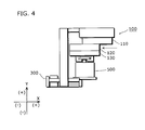
- FIG. 4 is a side view illustrating operations of the overhead traveling carriage in this embodiment according to the present invention.
- the holding unit 140 holds the article 500. Subsequently, the traveling unit 110 travels along the traveling rail 200 and stops in front of the platform 300.
- the delivery unit 120 moves the article 500 to the platform 300.
- the article 500 is held by the holding unit 140 of the overhead traveling carriage 100 such that the bottom of the article 500 is higher than the upper surface of the front wall 320 of the platform 300.
- the elevating unit 130 lowers the article 500, and mounts it on the platform 300.
- the elevating unit 130 of the overhead traveling carriage 100 lowers the article 500 so that the bottom of the article 500 becomes higher than the upper surface of the front wall 320 of the platform 300, and then the delivery unit 120 moves the article 500 above the platform 300.
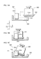
- FIGS. 5A to 5C is a diagram illustrating an operation of mounting the article 500 on the platform 300 and a position at which the safety member against overturning of the platform 300 is placed.
- the side walls 340 are not shown in each of FIGS. 5A to 5C .
- the article 500 is rectangular-shaped.
- the article 500 has abutting surfaces 510a facing upward, and has a protruding part 510 on the lower-most part of the side surface of the article 500.
- the abutting surfaces 510a are portions of the upper surface of the protruding part 510 formed on the side surface.
- the upper surface of the protruding part 510 of the article 500 includes the abutting surfaces 510a facing upward and having a predetermined height.
- the article 500 is stopped in front of the platform 300 through the operation performed by the traveling unit 110 of the overhead traveling carriage 100.
- the article 500 is placed such that the bottom of the article 500 is higher than the upper surface of the front wall 320 of the platform 300.
- the article 500 is moved, by the delivery unit 120 of the overhead traveling carriage 100, toward the platform 300 in the minus direction of the X-axis which approximately corresponds to the transfer direction on the horizontal plane.
- the tilt regulating part 350a is placed above the corresponding one of the abutting surfaces 510a of the article 500 while the article 500 is being transferred.
- the tilt regulating part 350a is placed at the position sufficiently higher than the abutting surface 510a such that the tilt regulating part 350a does not touch the abutting surface 510a even in the case where the tilt regulating part 350a sways.
- the tilt regulating part 350a is lowered to the lower-most position on condition that the tilt regulating part 350a does not touch the abutting surface 510a.
- the article 500 is moved above the platform 300, and then lowered by the elevating unit 130 of the overhead traveling carriage 100.
- the article 500 is mounted on the platform 300.
- the article 500 is transferred in the transfer direction, lowered, and mounted on the platform 300.
- the tilt regulating part 350a is placed so as not to touch the article 500.
- the tie part 350b and the fixing part 350c are arranged so as not to touch the article 500.
- FIGS. 6A to 6C is a diagram illustrating convex portions 311 of the receiving part 310 of the platform 300 in this embodiment according to the present invention.
- FIG. 6A is a view of the article 500 when seen from the bottom surface of the article 500. As shown in FIG. 6A , the article 500 has concave portions 520 on the bottom surface.
- FIG. 6B is a side view of the article 500 mounted on the platform 300.
- FIG. 6C is a cross-section view of the platform 300 and the article 500 shown in FIG. 6C when cut along the B-B line.
- the side walls 340 and the safety members against overturning 350 are not shown in FIG. 6C .
- the article 500 is mounted on the platform 300 such that three concave portions 520 on the bottom surface of the article 500 interfit with three convex portions 311 of the receiving part 310 of the platform 300, respectively.
- the article 500 is precisely positioned when the three concave portions 520 interfit with the three convex portions 311, respectively.
- FIGS. 7A and 7B are a diagram illustrating that the safety members against overturning 350 of the platform 300 prevent overturning of the article, and positions at which the safety members against overturning 350 are arranged.
- the side walls 340 are not shown in FIG. 7A
- the front wall 320 is not shown in FIG. 7B .
- the transfer direction of the article 500 is the X-axis direction
- the vertical direction is the Y-axis direction
- the direction vertical to the X-Y plane is the Z-axis direction.
- the article 500 may tilt toward the front wall 320 when a great quake such as an earthquake occurs. More specifically, the article 500 tilts toward the front wall 320 such that the article 500 rotates about the axis of the peripheral side abutting the front wall 320 among the four peripheral sides of the bottom surface of the article 500.
- the tilt regulating part 350a of the safety member against overturning is placed such that it can regulate the tilt range of the article 500 mounted on the platform 300 by abutting the corresponding one of the abutting surfaces 510a of the article 500.
- the tilt regulating part 350a is placed such that it abuts the abutting surface 510a of the article 500 when the article 500 tilts by a predetermined angle.
- the position of the X-axis direction of the tilt regulating part 350a is determined based on the position of the abutting surface 510a at the time when the article 500 tilts.
- the length of the X-axis direction of the tilt regulating part 350a is determined based on the position of the abutting surface 510a at the time when the article 500 tilts.
- the safety members against overturning 350 are arranged at positions in the depth direction of the platform 300 in the transfer direction. In other words, the safety members against overturning 350 are arranged such that it can prevent the article 500 from tilting in the direction of the front wall 320 and falling even when the tilt regulating part 350a is short in the X-axis direction.
- the tilt regulating part 350a can prevent the article 500 from tilting by a predetermined angle or more, it can prevent the article 500 from overturning and falling.
- FIG. 7B is a schematic side view of FIG. 7A when seen at the side of the front wall 320.
- two tilt regulating parts 350a are positioned respectively in relation to the abutting surfaces 510a formed in relation to the side surfaces of the article 500.
- the article 500 may tilt toward either one of the safety members against overturning 350 when a great quake such as an earthquake occurs. More specifically, the article 500 tilts toward either one of the side walls 340 such that it rotates about the axis of the side abutting the side wall 340 among the four peripheral sides of the bottom surface of the article 500.
- each of the tilt regulating parts 350a of the safety members against overturning 350 is arranged such that it can regulate the tilt range of the article 500 mounted on the platform 300 by abutting the corresponding one of the abutting surfaces 510a of the article 500.
- the tilt regulating part 350a is arranged such that it abuts the abutting surface 510a of the article 500 when the article 500 tilts by a predetermined angle.
- the position of the Z-axis direction of the tilt regulating part 350a is determined based on the position of the abutting surface 510a at the time when the article 500 tilts.
- the length of the Z-axis direction of the tilt regulating part 350a is determined based on the position of the abutting surface 510a at the time when the article 500 tilts.
- the tilt regulating part 350a can prevent the article 500 from tilting by a predetermined angle or more, it can prevent the article 500 from overturning and falling.
- the two safety members against overturning 350 are arranged opposite to each other sandwiching the article 500, each of them can prevent the article 500 from overturning and falling when the article 500 tilts toward the corresponding one of the side walls 340. Furthermore, even when the article 500 includes a single protruding part 510 protruding from the side abutting either one of the two side walls 340, the corresponding safety member against overturning 350 can prevent the article 500 from overturning and falling.
- the safety members against overturning 350 of the platform 300 can prevent the article 500 from overturning and falling when a great quake such as an earthquake occurs.
- the article 500 mounted on the receiving part 310 may be swayed greatly because the receiving part 310 are suspended by the suspension parts 400, the safety members against overturning 350 can prevent the article 500 from overturning and falling even in such a case.
- the safety members against overturning 350 can prevent articles 500 having various shapes from overturning and falling as long as each article 500 has a protruding part 510 at the predetermined position.
- the safety members against overturning 350 prevent overturning of an article 500 having a protruding part 510 at its lower-most part.
- the safety members against overturning 350 are arranged at positions different from those in the embodiment in order to prevent overturning of an article 500 having a protruding part 510 at a position other than the lower-most part.
- FIGS. 8A to 8C is a diagram showing the arrangement of the safety members against overturning 350 of the suspended platform 300 according to this variation.
- FIG. 8A is a plan view schematically showing the arrangement of one of the safety members against overturning 350 of the platform 300 according to this variation.
- FIG. 8A the arrangement in FIG. 8A is the same as the arrangement in the embodiment described with reference to FIG. 2A .
- FIG. 8B is a side view schematically showing the arrangement of the safety member against overturning 350 of the platform 300 according to this variation.
- the safety members against overturning 350 are arranged at the positions higher than those in the embodiment described with reference to FIGS. 2A and 2B .
- the safety members against overturning 350 are fixed on beams 360 and arranged such that the lower surfaces of the fixing parts 350c are flush with the lower surfaces of the receiving parts 310.
- the respective safety members against overturning 350 are arranged such that the lower surfaces of the fixing parts 350c are arranged at positions higher than those of the lower surfaces of the receiving parts 310, and the fixing parts 350c are attached to the side walls 340, respectively.
- FIGS. 9A to 9C are a diagram illustrating that the safety member against overturning 350 of the platform 300 prevents overturning of the article, and a position at which the safety member against overturning 350 is placed.
- the side walls 340 are not shown in FIGS. 9A to 9C .
- the article 500 has a protruding part 510 at the position appropriately higher than the lower-most part of the side surface.
- This protruding part 510 includes an upper surface including abutting surfaces 510a facing upward.
- the article 500 is stopped in front of the platform 300 through an operation performed by the traveling unit 110 of the overhead traveling carriage 100.
- the article 500 is placed such that the bottom surface of the article 500 is higher than the upper surface of the front wall 320 of the platform 300.
- the article 500 is transferred, by an operation performed by the delivery unit 120 of the overhead traveling carriage 100, in the minus direction of the X-axis which approximately corresponds to the transfer direction on the horizontal plane.
- the safety members against overturning 350 are arranged above the abutting surfaces 510a of the article 500 while the article 500 is being transferred.
- the article 500 is lowered in the minus direction of the Y-axis by the elevating unit 130, and mounted on the platform 300.
- the tilt regulating parts 350a are positioned such that they do not touch the article 500 when the article 500 is transferred and mounted.
- the tie parts 350b, and the fixing parts 350c are positioned such that they do not touch the article 500 when the article 500 is transferred and mounted.
- the tilt regulating parts 350a are positioned such that each of them abuts the corresponding one of the abutting surfaces 510a of the protruding part 510 of the article 500 in the case where the article 500 tilts toward the front wall 320 or where the article 500 tilts toward the side walls 340.
- the positions and sizes of the tilt regulating parts 350a are determined based on the position of the corresponding ones of the abutting surfaces 510a at the time when the article 500 tilts.
- the tilt regulating parts 350a can prevent the article 500 from tilting by a predetermined angle in this way, and thus it can prevent the article 500 from overturning and falling.
- the platforms 300 in the embodiment and this variation have two safety members against overturning 350, but it is also good that a single, or three or more safety members against overturning 350 is/are provided with the platforms 300.
- the safety members against overturning 350 are U-shaped in the embodiment and this variation, but the shape is not limited to U-shape as long as the safety members against overturning 350 can abut the abutting surface 510a of the protruding part 510 of the article 500, and thereby preventing falling of the article 500.
- Exemplary shapes include a shape formed only of a tilt regulating part 350a or of a tilt regulating part 350a and a tie part 350b.
- the safety members against overturning 350 are plates which extend in the approximately horizontal direction, and the safety members against overturning 350 may have any other shapes as long as the safety members against overturning 350 can abut the abutting surface 510a of the protruding part 510 of the article 500, and thereby preventing falling of the article 500.
- each of the safety members against overturning 350 prevents the article 500 from overturning by means that its tilt regulating part 350a abuts the corresponding one of the abutting surfaces 510a of the protruding part 510 of the article 500.
- each of the safety members against overturning 350 prevents an article 500 from overturning by means that its tilt regulating part 350a abuts the corresponding one of the abutting surfaces 510a which are portions of the upper surface of the article 500 without any protruding part 510.
- These safety members against overturning 350 can prevent overturning of the article 500 even in the case of the article 500 without any protruding part 510.
- the safety members against overturning 350 are arranged at positions closer to the depth walls 330 than to the front wall 320 of the platforms 300. However, it is also good that the safety members against overturning 350 are arranged at positions closer to the front wall 320 than to the depth walls 330 of the platforms 300, or at the midpoint between the front wall 320 and the depth walls 330. In addition, the safety members against overturning 350 may short or long in the depth direction. For example, the safety members against overturning 350 having the same length in the depth direction as that of the platforms 300 may be arranged.
- the safety members against overturning 350 are rigid bodies in the embodiment and this variation, but they are not limited to rigid bodies. More specifically, each of the safety members against overturning 350 may be made of materials which transform to a certain degree as long as they can regulate the tilt range of the article 500 mounted on the platforms 300 by abutting the corresponding one of the abutting surfaces 510a of the article 500.
- the receiving parts 310 of the respective platforms 300 have three convex portions 311 in the embodiment and this variation, but the number of convex portions 311 may be any including zero.
- the present invention is applicable as platforms on which articles conveyed by overhead traveling carriages are mounted, and in particular as platforms which can prevent articles from overturning and falling even when a great quake such as an earthquake occurs.
Landscapes
- Engineering & Computer Science (AREA)
- Mechanical Engineering (AREA)
- Computer Hardware Design (AREA)
- Power Engineering (AREA)
- Microelectronics & Electronic Packaging (AREA)
- Physics & Mathematics (AREA)
- Condensed Matter Physics & Semiconductors (AREA)
- General Physics & Mathematics (AREA)
- Manufacturing & Machinery (AREA)
- Robotics (AREA)
- Transportation (AREA)
- Structural Engineering (AREA)
- Civil Engineering (AREA)
- Warehouses Or Storage Devices (AREA)
- Control And Safety Of Cranes (AREA)
- Handcart (AREA)
Applications Claiming Priority (1)
| Application Number | Priority Date | Filing Date | Title |
|---|---|---|---|
| JP2008039177A JP2009196748A (ja) | 2008-02-20 | 2008-02-20 | 載置台 |
Publications (2)
| Publication Number | Publication Date |
|---|---|
| EP2093795A1 true EP2093795A1 (de) | 2009-08-26 |
| EP2093795B1 EP2093795B1 (de) | 2011-04-13 |
Family
ID=40552007
Family Applications (1)
| Application Number | Title | Priority Date | Filing Date |
|---|---|---|---|
| EP09002276A Expired - Fee Related EP2093795B1 (de) | 2008-02-20 | 2009-02-18 | Schwebebühne für Überkopffahrwagen |
Country Status (8)
| Country | Link |
|---|---|
| US (1) | US7828164B2 (de) |
| EP (1) | EP2093795B1 (de) |
| JP (1) | JP2009196748A (de) |
| KR (1) | KR20090090258A (de) |
| CN (1) | CN101513958B (de) |
| DE (1) | DE602009001016D1 (de) |
| SG (1) | SG155135A1 (de) |
| TW (1) | TWI438124B (de) |
Cited By (1)
| Publication number | Priority date | Publication date | Assignee | Title |
|---|---|---|---|---|
| EP2554494A1 (de) * | 2010-04-02 | 2013-02-06 | Murata Machinery, Ltd. | Seitlicher dämpfer für ein entlang einer decke fahrendes transportfahrzeug und transportfahrzeugsystem |
Families Citing this family (2)
| Publication number | Priority date | Publication date | Assignee | Title |
|---|---|---|---|---|
| DE102009031099A1 (de) * | 2009-06-29 | 2010-12-30 | Ista International Gmbh | Rauchwarnmelder und Verfahren zur Überprüfung der Verschmutzung der Rauchdurchtrittsöffnungen |
| TWI415785B (zh) * | 2011-01-12 | 2013-11-21 | Inotera Memories Inc | 天車輸送系統與其操作方法 |
Citations (6)
| Publication number | Priority date | Publication date | Assignee | Title |
|---|---|---|---|---|
| JPH05201506A (ja) * | 1992-01-27 | 1993-08-10 | Shinko Electric Co Ltd | クリーンルーム用保管庫 |
| US20020114685A1 (en) * | 2001-02-22 | 2002-08-22 | Yoshitaka Inui | Article storage system |
| US6468021B1 (en) * | 1998-12-18 | 2002-10-22 | Asyst Technologies, Inc. | Integrated intra-bay transfer, storage, and delivery system |
| JP2004315191A (ja) * | 2003-04-18 | 2004-11-11 | Daifuku Co Ltd | 物品保管設備の落下防止装置 |
| JP2005206371A (ja) | 2003-12-26 | 2005-08-04 | Murata Mach Ltd | 天井走行車システム |
| JP2008039177A (ja) | 2006-07-12 | 2008-02-21 | Yamaha Motor Co Ltd | ベルト式無段変速機、鞍乗型車両、およびベルト式無段変速機のシーブの製造方法 |
Family Cites Families (3)
| Publication number | Priority date | Publication date | Assignee | Title |
|---|---|---|---|---|
| US5363867A (en) | 1992-01-21 | 1994-11-15 | Shinko Electric Co., Ltd. | Article storage house in a clean room |
| TWI233913B (en) * | 2002-06-06 | 2005-06-11 | Murata Machinery Ltd | Automated guided vehicle system |
| JP2004059223A (ja) * | 2002-07-29 | 2004-02-26 | Murata Mach Ltd | 物品収納装置 |
-
2008
- 2008-02-20 JP JP2008039177A patent/JP2009196748A/ja active Pending
- 2008-10-30 TW TW097141779A patent/TWI438124B/zh not_active IP Right Cessation
- 2008-12-15 KR KR1020080127191A patent/KR20090090258A/ko not_active Application Discontinuation
-
2009
- 2009-02-17 SG SG200901123-0A patent/SG155135A1/en unknown
- 2009-02-18 EP EP09002276A patent/EP2093795B1/de not_active Expired - Fee Related
- 2009-02-18 US US12/379,292 patent/US7828164B2/en not_active Expired - Fee Related
- 2009-02-18 DE DE602009001016T patent/DE602009001016D1/de active Active
- 2009-02-18 CN CN2009100093170A patent/CN101513958B/zh not_active Expired - Fee Related
Patent Citations (6)
| Publication number | Priority date | Publication date | Assignee | Title |
|---|---|---|---|---|
| JPH05201506A (ja) * | 1992-01-27 | 1993-08-10 | Shinko Electric Co Ltd | クリーンルーム用保管庫 |
| US6468021B1 (en) * | 1998-12-18 | 2002-10-22 | Asyst Technologies, Inc. | Integrated intra-bay transfer, storage, and delivery system |
| US20020114685A1 (en) * | 2001-02-22 | 2002-08-22 | Yoshitaka Inui | Article storage system |
| JP2004315191A (ja) * | 2003-04-18 | 2004-11-11 | Daifuku Co Ltd | 物品保管設備の落下防止装置 |
| JP2005206371A (ja) | 2003-12-26 | 2005-08-04 | Murata Mach Ltd | 天井走行車システム |
| JP2008039177A (ja) | 2006-07-12 | 2008-02-21 | Yamaha Motor Co Ltd | ベルト式無段変速機、鞍乗型車両、およびベルト式無段変速機のシーブの製造方法 |
Cited By (2)
| Publication number | Priority date | Publication date | Assignee | Title |
|---|---|---|---|---|
| EP2554494A1 (de) * | 2010-04-02 | 2013-02-06 | Murata Machinery, Ltd. | Seitlicher dämpfer für ein entlang einer decke fahrendes transportfahrzeug und transportfahrzeugsystem |
| EP2554494A4 (de) * | 2010-04-02 | 2014-07-30 | Murata Machinery Ltd | Seitlicher dämpfer für ein entlang einer decke fahrendes transportfahrzeug und transportfahrzeugsystem |
Also Published As
| Publication number | Publication date |
|---|---|
| DE602009001016D1 (de) | 2011-05-26 |
| US7828164B2 (en) | 2010-11-09 |
| US20090206048A1 (en) | 2009-08-20 |
| JP2009196748A (ja) | 2009-09-03 |
| CN101513958B (zh) | 2013-03-20 |
| TW200936467A (en) | 2009-09-01 |
| TWI438124B (zh) | 2014-05-21 |
| EP2093795B1 (de) | 2011-04-13 |
| CN101513958A (zh) | 2009-08-26 |
| KR20090090258A (ko) | 2009-08-25 |
| SG155135A1 (en) | 2009-09-30 |
Similar Documents
| Publication | Publication Date | Title |
|---|---|---|
| CN107614397B (zh) | 平面保管设备的出入库装置的控制方法 | |
| US10625938B2 (en) | Article transport facility | |
| KR101359682B1 (ko) | 천장을 주행하는 반송차의 사이드 버퍼 및 반송차 시스템 | |
| JP2008081301A (ja) | スタッカクレーン | |
| TWI508911B (zh) | Stacker | |
| CN107804641B (zh) | 物品输送装置 | |
| JP6773123B2 (ja) | 搬送システム | |
| EP2093795B1 (de) | Schwebebühne für Überkopffahrwagen | |
| EP3680201A1 (de) | Vorrichtung und verfahren zum handeln von scheibenelementen | |
| US20160176461A1 (en) | Vehicle assembly line | |
| JP2016155659A (ja) | 搬送装置 | |
| JP6579190B2 (ja) | 物品搬送装置 | |
| JP2012051674A (ja) | 昇降装置 | |
| JP5045186B2 (ja) | スタッカクレーン及び自動倉庫 | |
| CN212330336U (zh) | 横梁结构及具有其的机床 | |
| JP6287698B2 (ja) | 物品搬送装置 | |
| US9764898B2 (en) | Automated warehouse and operation method for same | |
| JP2013230911A (ja) | 立体自動倉庫のラックに用いるパレット落下防止装置 | |
| JP4458732B2 (ja) | 枠組体の立設方法 | |
| JP2021046271A (ja) | ラック | |
| KR102451382B1 (ko) | 반송 시스템 | |
| JP6287699B2 (ja) | 物品搬送装置 | |
| JP5428153B2 (ja) | 収容棚及び自動倉庫 | |
| JP2012126238A (ja) | 自動搬送車 | |
| JP7149036B2 (ja) | パネル受け台、及びパネル取り出し方法 |
Legal Events
| Date | Code | Title | Description |
|---|---|---|---|
| PUAI | Public reference made under article 153(3) epc to a published international application that has entered the european phase |
Free format text: ORIGINAL CODE: 0009012 |
|
| AK | Designated contracting states |
Kind code of ref document: A1 Designated state(s): AT BE BG CH CY CZ DE DK EE ES FI FR GB GR HR HU IE IS IT LI LT LU LV MC MK MT NL NO PL PT RO SE SI SK TR |
|
| AX | Request for extension of the european patent |
Extension state: AL BA RS |
|
| 17P | Request for examination filed |
Effective date: 20090910 |
|
| AKX | Designation fees paid |
Designated state(s): DE FR IT |
|
| GRAP | Despatch of communication of intention to grant a patent |
Free format text: ORIGINAL CODE: EPIDOSNIGR1 |
|
| GRAS | Grant fee paid |
Free format text: ORIGINAL CODE: EPIDOSNIGR3 |
|
| GRAA | (expected) grant |
Free format text: ORIGINAL CODE: 0009210 |
|
| AK | Designated contracting states |
Kind code of ref document: B1 Designated state(s): DE FR IT |
|
| REF | Corresponds to: |
Ref document number: 602009001016 Country of ref document: DE Date of ref document: 20110526 Kind code of ref document: P |
|
| REG | Reference to a national code |
Ref country code: DE Ref legal event code: R096 Ref document number: 602009001016 Country of ref document: DE Effective date: 20110526 |
|
| PLBE | No opposition filed within time limit |
Free format text: ORIGINAL CODE: 0009261 |
|
| STAA | Information on the status of an ep patent application or granted ep patent |
Free format text: STATUS: NO OPPOSITION FILED WITHIN TIME LIMIT |
|
| 26N | No opposition filed |
Effective date: 20120116 |
|
| REG | Reference to a national code |
Ref country code: DE Ref legal event code: R097 Ref document number: 602009001016 Country of ref document: DE Effective date: 20120116 |
|
| PGFP | Annual fee paid to national office [announced via postgrant information from national office to epo] |
Ref country code: IT Payment date: 20150227 Year of fee payment: 7 |
|
| REG | Reference to a national code |
Ref country code: FR Ref legal event code: PLFP Year of fee payment: 8 |
|
| PGFP | Annual fee paid to national office [announced via postgrant information from national office to epo] |
Ref country code: FR Payment date: 20160218 Year of fee payment: 8 |
|
| PG25 | Lapsed in a contracting state [announced via postgrant information from national office to epo] |
Ref country code: IT Free format text: LAPSE BECAUSE OF NON-PAYMENT OF DUE FEES Effective date: 20160218 |
|
| REG | Reference to a national code |
Ref country code: FR Ref legal event code: ST Effective date: 20171031 |
|
| PG25 | Lapsed in a contracting state [announced via postgrant information from national office to epo] |
Ref country code: FR Free format text: LAPSE BECAUSE OF NON-PAYMENT OF DUE FEES Effective date: 20170228 |
|
| PGFP | Annual fee paid to national office [announced via postgrant information from national office to epo] |
Ref country code: DE Payment date: 20180219 Year of fee payment: 10 |
|
| REG | Reference to a national code |
Ref country code: DE Ref legal event code: R119 Ref document number: 602009001016 Country of ref document: DE |
|
| PG25 | Lapsed in a contracting state [announced via postgrant information from national office to epo] |
Ref country code: DE Free format text: LAPSE BECAUSE OF NON-PAYMENT OF DUE FEES Effective date: 20190903 |