EP2092869A2 - Nozzle for floor vacuum cleaner - Google Patents
Nozzle for floor vacuum cleaner Download PDFInfo
- Publication number
- EP2092869A2 EP2092869A2 EP09001365A EP09001365A EP2092869A2 EP 2092869 A2 EP2092869 A2 EP 2092869A2 EP 09001365 A EP09001365 A EP 09001365A EP 09001365 A EP09001365 A EP 09001365A EP 2092869 A2 EP2092869 A2 EP 2092869A2
- Authority
- EP
- European Patent Office
- Prior art keywords
- axis
- chassis
- suction
- suction head
- nozzle
- Prior art date
- Legal status (The legal status is an assumption and is not a legal conclusion. Google has not performed a legal analysis and makes no representation as to the accuracy of the status listed.)
- Granted
Links
- 238000007789 sealing Methods 0.000 claims description 4
- 238000011144 upstream manufacturing Methods 0.000 claims 1
- 235000004443 Ricinus communis Nutrition 0.000 abstract 1
- 239000000428 dust Substances 0.000 description 5
- 230000002349 favourable effect Effects 0.000 description 5
- 230000002411 adverse Effects 0.000 description 2
- 238000004140 cleaning Methods 0.000 description 2
- 150000001875 compounds Chemical class 0.000 description 2
- 238000010521 absorption reaction Methods 0.000 description 1
- 230000005540 biological transmission Effects 0.000 description 1
- 230000000052 comparative effect Effects 0.000 description 1
- 239000002131 composite material Substances 0.000 description 1
- 230000008092 positive effect Effects 0.000 description 1
- 239000000725 suspension Substances 0.000 description 1
- 239000004753 textile Substances 0.000 description 1
- 239000013598 vector Substances 0.000 description 1
Images

Classifications
-
- A—HUMAN NECESSITIES
- A47—FURNITURE; DOMESTIC ARTICLES OR APPLIANCES; COFFEE MILLS; SPICE MILLS; SUCTION CLEANERS IN GENERAL
- A47L—DOMESTIC WASHING OR CLEANING; SUCTION CLEANERS IN GENERAL
- A47L9/00—Details or accessories of suction cleaners, e.g. mechanical means for controlling the suction or for effecting pulsating action; Storing devices specially adapted to suction cleaners or parts thereof; Carrying-vehicles specially adapted for suction cleaners
- A47L9/02—Nozzles
- A47L9/06—Nozzles with fixed, e.g. adjustably fixed brushes or the like
Definitions
- the invention relates to a nozzle for vacuum cleaner.
- the invention relates to a floor nozzle with a chassis, which has a rear chassis section with at least one roller and a front projecting in the suction direction front portion for connecting a suction head.
- the suction head is tiltably mounted about a horizontal axis at the front portion of the chassis.
- a SaugrohranQuery Swiss is provided, which is arranged pivotably about a horizontal hinge axis on the chassis.
- a floor nozzle with the features described is out DE-A 28 46 847 known.
- the hinge axis of the Saugrohran gleich Swisses coincides with the axis of the roller.
- the chassis forms a suction channel, at the front portion of the suction head is mounted tiltably about a horizontal axis.
- the force introduced during use of the floor nozzle via the Saugrohran gleich congress is transmitted to the roller, which receives the vertical forces.
- the function of the floor nozzle during a backward movement of the chassis is in need of improvement. Due to the very low point of articulation of Saugrohran gleich publishedes there is a risk that the landing gear is lifted in a backward movement of the bottom surface and the suction head is inclined to the bottom surface, which adversely affects the dust intake.
- WO 03/039315 is a floor nozzle for vacuum cleaner known which has better performance in a backward movement.
- the nozzle also consists of a chassis that a rear chassis section having two rollers arranged on an axis and a front projecting in the suction direction front portion for connection of a suction head, and a suction head which is tiltably mounted about a horizontal axis on the front portion of the chassis.
- the Saugrohran gleich Swiss is connected to a rocker which is pivotally mounted on the front chassis section about a horizontal axis. The hinge axis of the rocker and the axis for the movable mounting of the suction head coincide.
- the Saugrohran gleich Swiss connected to the rocker is vertically movably guided on the rear chassis section and occupies different positions relative to the axis of the rollers during forward and backward movements of the chassis.
- the rocker and the Saugrohran gleich Swiss go into an extended position, without the risk that the landing gear is lifted from the ground.
- the forces occurring during the handling of the floor nozzle are introduced via the suction pipe connection piece and the rocker into the front section of the chassis. In a forward movement, this leads to a load on the suction head, which increases the pushing force. In a backward movement of the suction head of the suction head is relieved, which can adversely affect the dust pickup.
- the force distribution in the handling of the nozzle is still in need of improvement.
- the invention has for its object to provide a nozzle for vacuum cleaner, which always rests flat on the floor surface in forward and backward movements. Furthermore, a favorable force distribution of the introduced via the Saugrohran gleich Swiss force is aimed at both a forward movement of the floor nozzle as well as a backward movement of the floor nozzle.
- connection between the hinge axle and the rear chassis section is in an area which starts in the suction direction 20 mm in front of the axis of the rollers and ends 20 mm behind the axis of the rollers.
- the connection by which the forces are transmitted from a suction pipe connected to the Saugrohran gleich Swiss on the chassis, arranged approximately in a vertical axis laid by the roller axis.
- the force application point of the connection is mounted vertically movable and assumes at a forward movement of the floor nozzle and a backward movement of the nozzle different positions, which do not coincide with the roller axis. Due to the distance of the force introduction point of the roller axis, a lever arm, which results as a product with the force introduced through the suction pipe torque.
- the force application points can be determined by the vertical mobility of the compound so that when forward and backward movements of the floor nozzle different torques arise, which have a favorable effect on the suction properties of the nozzle.
- the connection between the hinge axis and the chassis is designed so that the hinge axis occupies a position below the axis of the rollers during a forward movement of the chassis and a position above the roller axis during a backward movement.
- the connection between the joint axis of the Saugrohran gleich Swisses and the rear suspension section can be realized in a simple manner constructively characterized in that the hinge axis of the Saugrohran gleich Swisses is guided vertically movable in the guide recesses.
- the guide recesses are arranged on the rear chassis section and the rear chassis section forming roller carrier and expediently have an upper stop and a lower stop for the hinge axis.
- the stops are set so that, when the nozzle is in use, the hinge axis bears against the lower stop during forward movement of the chassis and against the upper stop during rearward movement of the chassis.
- the guide recesses are perpendicular or inclined at an angle of 60 ° maximum to the vertical. In the context of the invention, it is also that they are arcuately curved.
- the suction pipe connecting the suction pipe with the pipe for guiding the suction air is flexible in order not to hinder the force distribution achieved with the vertically movable force application point and to influence.
- the air duct and the power transmission are preferably functionally separated.
- a preferred embodiment of the invention provides that the flexible conduit consists of a corrugated hose or a multipart channel movably composed of segments.
- the suction head has a sliding sole with one or more suction slots which extend across the width of the suction head.
- the sliding sole can rest directly on the surface to be cleaned or be supported on front rollers.
- Preferred is a sole with a sole Suction slot which extends over the entire width of the suction head and rests directly on the floor surface when cleaning textile floor surfaces.
- the suction head on the bottom side retractable and sealing strips, for example in the form of a bristle ring, in the form of bristle strips or sealing lips.
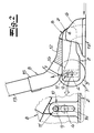
- the floor nozzle shown in the figures has a chassis 1, which has a rear chassis section 2 with a roller 3 or two arranged on an axis 4 rollers 3 and a projecting in the suction direction front portion 5 for connecting a suction head 6.
- the suction head 6 is tiltably mounted about a horizontal axis 7 on the front portion 5 of the chassis.
- a Saugrohran gleich conspiracy 8 is provided, which is arranged about a horizontal hinge axis 9 pivotally mounted on the chassis 1.
- the hinge axis 9 of the Saugrohran gleich dealtes 8 is connected by a connection 10, which transmits sliding forces between the Saugrohran gleich institutions 8 and the chassis 1, vertically movably connected to the rear chassis section 2.
- a flexible conduit 12 is provided, which is formed for example as a corrugated hose or may consist of a segmentally movable composite multi-part channel.
- connection 10 between the hinge axle 9 and the rear chassis section 2 is in a region which starts in the suction direction 20 mm in front of the axis 4 of the rollers 3 and ends 20 mm behind the axis of the rollers.
- the connection 10 is located substantially in a vertical plane passing through the roller axle 4.
- the connection between the hinge axis 9 and the rear chassis section 2 transmits forces that occur in the handling of a suction pipe connected to the suction pipe 8 suction pipe 13 and in the Fig. 1 and 2 are shown as force vectors F 1 , F 2 .
- the connection between the hinge axis 9 and the chassis 1 is formed so that the hinge axis 9 assumes a position 11 under a forward movement of the chassis 1 below the axis 4 of the rollers 3 ( Fig. 1 ) and in a backward movement, a position 11 'above the roller axis 4 is set ( Fig. 2 ).
- a lever arm is formed which, as a product, results in a torque with the force introduced through the suction tube.
- a torque is generated, which reduces the contact force of the suction head 6 on the bottom surface and thereby reduces the applied for the forward movement of sliding force.
- the backward movement creates a moment which counteracts the occurring during the backward movement relief of the suction head 6 and has a positive effect on the dust pickup during the backward movement.
- the hinge axis 9 of the Saugrohran gleich Swisses 8 To connect the hinge axis 9 of the Saugrohran gleich Swisses 8 with the rear chassis section 2 guide recesses 14 are provided in which the hinge axis 9 is guided vertically movable.
- the guide recesses 14 are arranged on a wall surface of the rear chassis section 2.
- the rear chassis section 2 consists of a roller carrier on which webs with the guide recesses 14 are arranged.
- the guide recesses 14 extend in the embodiment vertically. They may also be inclined at an angle to the vertical or arcuately curved.
- the guide recesses 14 form an upper stop and a lower stop for the hinge axis 9 of the Saugrohran gleich Swisses 8.
- the hinge axis 9 is during forward movement of the chassis at the lower stop and during a backward movement of the chassis to the upper stop.
- the SaugrohranInstitut Nursing 8 is formed in a conventional manner as a rotary joint. It has a curved connection end 15 and a pipe stub 16 connected to the flexible pipe 12, which is inserted in a rotatable manner into the curved pipe connection end 15.
- the suction head 6 has a sliding sole 17 with one or more suction slots, which extend transversely to the direction of movement of the floor nozzle over the entire width of the suction head.
- the sliding sole 17 is in the embodiment on the bottom surface. It is not excluded that the sliding sole is also supported on rollers on the bottom side. Finally, in the suction head on the bottom side retractable and sealing strips may be provided, which are extended to clean smooth floor coverings.
Abstract
Description
Die Erfindung betrifft eine Düse für Bodenstaubsauger.The invention relates to a nozzle for vacuum cleaner.
Die Erfindung geht aus von einer Bodendüse mit einem Fahrwerk, das einen rückwärtigen Fahrwerksabschnitt mit mindestens einer Laufrolle und einem in Saugrichtung vorkragenden vorderen Abschnitt zum Anschluss eines Saugkopfes aufweist. Der Saugkopf ist um eine horizontale Achse kippbeweglich an dem vorderen Abschnitt des Fahrwerks gelagert. Ferner ist ein Saugrohranschlussstück vorgesehen, welches um eine horizontale Gelenkachse verschwenkbar an dem Fahrwerk angeordnet ist.The invention relates to a floor nozzle with a chassis, which has a rear chassis section with at least one roller and a front projecting in the suction direction front portion for connecting a suction head. The suction head is tiltably mounted about a horizontal axis at the front portion of the chassis. Furthermore, a Saugrohranschlussstück is provided, which is arranged pivotably about a horizontal hinge axis on the chassis.
Eine Bodendüse mit den beschriebenen Merkmalen ist aus
Aus
Der Erfindung liegt die Aufgabe zugrunde, eine Düse für Bodenstaubsauger anzugeben, die bei Vorwärts- und Rückwärtsbewegungen stets flächig auf der Bodenfläche aufliegt. Ferner wird eine günstige Kraftverteilung der über das Saugrohranschlussstück eingeleiteten Kraft sowohl bei einer Vorwärtsbewegung der Bodendüse als auch bei einer Rückwärtsbewegung der Bodendüse angestrebt.The invention has for its object to provide a nozzle for vacuum cleaner, which always rests flat on the floor surface in forward and backward movements. Furthermore, a favorable force distribution of the introduced via the Saugrohranschlussstück force is aimed at both a forward movement of the floor nozzle as well as a backward movement of the floor nozzle.
Gegenstand der Erfindung und Lösung dieser Aufgabe ist eine Düse für Bodenstaubsauger mit
- einem Fahrwerk, das einen rückwärtigen Fahrwerksabschnitt mit mindestens einer Laufrolle und einen in Saugrichtung vorkragenden vorderen Abschnitt zum Anschluss eines Saugkopfes aufweist,
- einem Saugkopf, der um eine horizontale Achse kippbeweglich an dem vorderen Abschnitt des Fahrwerks gelagert ist, und
- einem Saugrohranschlussstück, welches um eine horizontale Gelenkachse verschwenkbar an dem Fahrwerk angeordnet ist,
- a chassis which has a rear chassis section with at least one roller and a front section protruding in the suction direction for connecting a suction head,
- a suction head, which is mounted tiltably about a horizontal axis on the front portion of the chassis, and
- a Saugrohranschlussstück which is arranged pivotably about a horizontal hinge axis on the chassis,
Die Verbindung zwischen der Gelenkachse und dem rückwärtigen Fahrwerksabschnitt liegt in einem Bereich, der in Saugrichtung 20 mm vor der Achse der Laufrollen beginnt und 20 mm hinter der Achse der Laufrollen endet. Vorzugsweise ist die Verbindung, durch welche die Kräfte von einem an das Saugrohranschlussstück angeschlossenen Saugrohr auf das Fahrwerk übertragen werden, etwa in einer durch die Rollenachse gelegten vertikalen Ebene angeordnet. Der Krafteinleitungspunkt der Verbindung ist jedoch vertikal beweglich gelagert und nimmt bei einer Vorwärtsbewegung der Bodendüse und bei einer Rückwärtsbewegung der Düse unterschiedliche Positionen ein, die nicht mit der Rollenachse zusammenfallen. Durch den Abstand des Krafteinleitungspunktes von der Rollenachse entsteht ein Hebelarm, der als Produkt mit der durch das Saugrohr eingeleiteten Kraft ein Drehmoment ergibt. Die Krafteinleitungspunkte können dabei durch die vertikale Beweglichkeit der Verbindung so festgelegt werden, dass bei Vorwärts- und Rückwärtsbewegungen der Bodendüse unterschiedliche Drehmomente entstehen, die sich günstig auf die Saugeigenschaften der Düse auswirken. Gemäß einer bevorzugten Ausführung der Erfindung ist die Verbindung zwischen der Gelenkachse und dem Fahrwerk so ausgebildet, dass die Gelenkachse bei einer Vorwärtsbewegung des Fahrwerkes eine Position unterhalb der Achse der Laufrollen und bei einer Rückwärtsbewegung eine Position oberhalb der Laufrollenachse einnimmt. Durch die Position des Krafteinleitungspunktes unterhalb der Rollenachse während einer Vorwärtsbewegung des Fahrwerkes kann ein Drehmoment erzeugt werden, welches die Auflagekraft des Saugkopfes auf der Bodenfläche reduziert und die Schiebekraft bei einer Vorwärtsbewegung mindert. Durch den höheren Krafteinleitungspunkt, der sich bei einer Rückwärtsbewegung einstellt, kann ein Moment erzeugt werden, welches der üblicherweise bei einer Rückwärtsbewegung auftretenden Entlastung des Saugkopfes entgegenwirkt und sich günstig auf die Staubaufnahme während einer Rückwärtsbewegung des Fahrwerkes auswirkt.The connection between the hinge axle and the rear chassis section is in an area which starts in the suction direction 20 mm in front of the axis of the rollers and ends 20 mm behind the axis of the rollers. Preferably, the connection, by which the forces are transmitted from a suction pipe connected to the Saugrohranschlussstück on the chassis, arranged approximately in a vertical axis laid by the roller axis. However, the force application point of the connection is mounted vertically movable and assumes at a forward movement of the floor nozzle and a backward movement of the nozzle different positions, which do not coincide with the roller axis. Due to the distance of the force introduction point of the roller axis, a lever arm, which results as a product with the force introduced through the suction pipe torque. The force application points can be determined by the vertical mobility of the compound so that when forward and backward movements of the floor nozzle different torques arise, which have a favorable effect on the suction properties of the nozzle. According to a preferred embodiment of the invention, the connection between the hinge axis and the chassis is designed so that the hinge axis occupies a position below the axis of the rollers during a forward movement of the chassis and a position above the roller axis during a backward movement. By the position of the force application point below the roller axis during forward movement of the chassis, a torque can be generated which reduces the contact force of the suction head on the floor surface and reduces the sliding force in a forward movement. Due to the higher force introduction point, which sets in a backward movement, a moment can be generated, which counteracts the usually occurring in a backward movement relief of the suction head and has a favorable effect on the dust absorption during a rearward movement of the chassis.
Die erfindungsgemäße Verbindung zwischen der Gelenkachse des Saugrohranschlussstückes und dem rückwärtigen Fahrwerksabschnitt kann auf einfache Weise konstruktiv dadurch realisiert werden, dass die Gelenkachse des Saugrohranschlussstückes endseitig in Führungsausnehmungen vertikal beweglich geführt ist. Die Führungsausnehmungen sind an dem rückwärtigen Fahrwerksabschnitt bzw. einem den rückwärtigen Fahrwerksabschnitt bildenden Laufrollenträger angeordnet und weisen zweckmäßig einen oberen Anschlag und einen unteren Anschlag für die Gelenkachse auf. Die Anschläge sind so festgelegt, dass die Gelenkachse beim Gebrauch der Düse während einer Vorwärtsbewegung des Fahrwerks an dem unteren Anschlag und während einer Rückwärtsbewegung des Fahrwerks an dem oberen Anschlag anliegt. Die Führungsausnehmungen verlaufen senkrecht oder sind unter einem Winkel von maximal 60° zur Senkrechten geneigt. Im Rahmen der Erfindung liegt es auch, dass sie bogenförmig gekrümmt sind.The connection between the joint axis of the Saugrohranschlussstückes and the rear suspension section can be realized in a simple manner constructively characterized in that the hinge axis of the Saugrohranschlussstückes is guided vertically movable in the guide recesses. The guide recesses are arranged on the rear chassis section and the rear chassis section forming roller carrier and expediently have an upper stop and a lower stop for the hinge axis. The stops are set so that, when the nozzle is in use, the hinge axis bears against the lower stop during forward movement of the chassis and against the upper stop during rearward movement of the chassis. The guide recesses are perpendicular or inclined at an angle of 60 ° maximum to the vertical. In the context of the invention, it is also that they are arcuately curved.
Die den Saugkopf mit dem Saugrohranschlussstück verbindende Leitung zur Führung der Saugluft ist flexibel ausgebildet, um die mit dem vertikal beweglichen Krafteinleitungspunkt erreichte Kraftverteilung nicht zu behindern und zu beeinflussen. Die Luftführung und die Kraftübertragung werden vorzugsweise funktionstechnisch getrennt. Eine bevorzugte Ausführung der Erfindung sieht vor, dass die flexible Leitung aus einem Wellschlauch oder einem aus Segmenten beweglich zusammengesetzten mehrteiligen Kanal besteht.The suction pipe connecting the suction pipe with the pipe for guiding the suction air is flexible in order not to hinder the force distribution achieved with the vertically movable force application point and to influence. The air duct and the power transmission are preferably functionally separated. A preferred embodiment of the invention provides that the flexible conduit consists of a corrugated hose or a multipart channel movably composed of segments.
Der Saugkopf weist eine Gleitsohle mit einem oder mehreren Saugschlitzen auf, die sich über die Breite des Saugkopfes erstrecken. Die Gleitsohle kann unmittelbar auf der zu reinigenden Fläche aufliegen oder an vorderseitigen Laufrollen abgestützt sein. Bevorzugt ist eine Gleitsohle mit einem einzigen Saugschlitz der sich über die gesamte Breite des Saugkopfes erstreckt und beim Reinigen von textilen Bodenflächen unmittelbar auf der Bodenfläche aufliegt. Zur Reinigung von Glattböden kann der Saugkopf bodenseitig ein- und ausfahrbare Dichtstreifen, z.B. in Form eines Borstenkranzes, in Form von Borstenstreifen oder Dichtungslippen aufweisen.The suction head has a sliding sole with one or more suction slots which extend across the width of the suction head. The sliding sole can rest directly on the surface to be cleaned or be supported on front rollers. Preferred is a sole with a sole Suction slot which extends over the entire width of the suction head and rests directly on the floor surface when cleaning textile floor surfaces. For cleaning smooth floors, the suction head on the bottom side retractable and sealing strips, for example in the form of a bristle ring, in the form of bristle strips or sealing lips.
Im Folgenden wird die Erfindung anhand einer lediglich ein Ausführungsbeispiel darstellenden Zeichnung erläutert. Es zeigen schematisch:
- Fig. 1
- die Seitenansicht einer Düse für Bodenstaubsauger während einer Vorwärtsbewegung und
- Fig. 2
- die in
Fig. 1 dargestellte Düse während einer Rückwärtsbewegung.
- Fig. 1
- the side view of a nozzle for vacuum cleaner during a forward movement and
- Fig. 2
- in the
Fig. 1 illustrated nozzle during a backward movement.
Die in den Figuren dargestellte Bodendüse weist ein Fahrwerk 1 auf, das einen rückwärtigen Fahrwerksabschnitt 2 mit einer Laufrolle 3 bzw. zwei auf einer Achse 4 angeordneten Laufrollen 3 sowie einen in Saugrichtung vorkragenden vorderen Abschnitt 5 zum Anschluss eines Saugkopfes 6 aufweist. Der Saugkopf 6 ist um eine horizontale Achse 7 kippbeweglich an dem vorderen Abschnitt 5 des Fahrwerks gelagert. Ferner ist ein Saugrohranschlussstück 8 vorgesehen, welches um eine horizontale Gelenkachse 9 verschwenkbar an dem Fahrwerk 1 angeordnet ist. Die Gelenkachse 9 des Saugrohranschlussstückes 8 ist durch eine Verbindung 10, welche Schiebekräfte zwischen dem Saugrohranschlussstück 8 und dem Fahrwerk 1 überträgt, vertikal beweglich an den rückwärtigen Fahrwerksabschnitt 2 angeschlossen. Einer vergleichenden Betrachtung der
Die Verbindung 10 zwischen der Gelenkachse 9 und dem rückwärtigen Fahrwerksabschnitt 2 liegt in einem Bereich, der in Saugrichtung 20 mm vor der Achse 4 der Laufrollen 3 beginnt und 20 mm hinter der Achse der Laufrollen endet. Im Ausführungsbeispiel und gemäß einer bevorzugten Ausführung der Erfindung liegt die Verbindung 10 im Wesentlichen in einer durch die Laufrollenachse 4 verlaufenden vertikalen Ebene.The
Die Verbindung zwischen der Gelenkachse 9 und dem rückwärtigen Fahrwerksabschnitt 2 überträgt Kräfte, die bei der Handhabung eines an das Saugrohranschlussstück 8 angeschlossenen Saugrohres 13 auftreten und in den
Zur Verbindung der Gelenkachse 9 des Saugrohranschlussstückes 8 mit dem rückwärtigen Fahrwerksabschnitt 2 sind Führungsausnehmungen 14 vorgesehen, in denen die Gelenkachse 9 vertikal beweglich geführt ist. Die Führungsausnehmungen 14 sind an einer Wandfläche des rückwärtigen Fahrwerksabschnittes 2 angeordnet. Im Ausführungsbeispiel besteht der rückwärtige Fahrwerksabschnitt 2 aus einem Laufrollenträger, an dem Stege mit den Führungsausnehmungen 14 angeordnet sind. Die Führungsausnehmungen 14 verlaufen im Ausführungsbeispiel senkrecht. Sie können auch unter einem Winkel zur Senkrechten geneigt oder bogenförmig gekrümmt sein. Die Führungsausnehmungen 14 bilden einen oberen Anschlag und einen unteren Anschlag für die Gelenkachse 9 des Saugrohranschlussstückes 8. Beim Gebrauch der Düse liegt die Gelenkachse 9 während einer Vorwärtsbewegung des Fahrwerks an dem unteren Anschlag und während einer Rückwärtsbewegung des Fahrwerks an dem oberen Anschlag an.To connect the hinge axis 9 of the
Das Saugrohranschlussstück 8 ist in an sich bekannter Weise als Drehgelenk ausgebildet. Es weist ein gekrümmtes Anschlussende 15 sowie einen mit der flexiblen Leitung 12 verbundenen Rohrstutzen 16 auf, der in das gekrümmte Rohranschlussende 15 drehbeweglich eingesetzt ist.The
Der Saugkopf 6 weist eine Gleitsohle 17 mit einem oder mehreren Saugschlitzen auf, die sich quer zur Bewegungsrichtung der Bodendüse über die gesamte Breite des Saugkopfes erstrecken. Die Gleitsohle 17 liegt im Ausführungsbeispiel auf der Bodenfläche auf. Es ist nicht ausgeschlossen, dass die Gleitsohle auch an Rollen bodenseitig abgestützt ist. Schließlich können im Saugkopf bodenseitig ein- und ausfahrbare Dichtstreifen vorgesehen sein, die zum Reinigen von glatten Bodenbelägen ausgefahren werden.The suction head 6 has a sliding sole 17 with one or more suction slots, which extend transversely to the direction of movement of the floor nozzle over the entire width of the suction head. The sliding sole 17 is in the embodiment on the bottom surface. It is not excluded that the sliding sole is also supported on rollers on the bottom side. Finally, in the suction head on the bottom side retractable and sealing strips may be provided, which are extended to clean smooth floor coverings.
Claims (9)
Applications Claiming Priority (1)
| Application Number | Priority Date | Filing Date | Title |
|---|---|---|---|
| DE200810010897 DE102008010897A1 (en) | 2008-02-23 | 2008-02-23 | Nozzle for vacuum cleaner |
Publications (3)
| Publication Number | Publication Date |
|---|---|
| EP2092869A2 true EP2092869A2 (en) | 2009-08-26 |
| EP2092869A3 EP2092869A3 (en) | 2011-05-04 |
| EP2092869B1 EP2092869B1 (en) | 2015-06-24 |
Family
ID=40668414
Family Applications (1)
| Application Number | Title | Priority Date | Filing Date |
|---|---|---|---|
| EP09001365.7A Active EP2092869B1 (en) | 2008-02-23 | 2009-01-31 | Nozzle for floor vacuum cleaner |
Country Status (3)
| Country | Link |
|---|---|
| EP (1) | EP2092869B1 (en) |
| CN (1) | CN101513335B (en) |
| DE (1) | DE102008010897A1 (en) |
Cited By (8)
| Publication number | Priority date | Publication date | Assignee | Title |
|---|---|---|---|---|
| EP2449936A1 (en) * | 2010-11-05 | 2012-05-09 | Seb S.A. | Vacuum cleaner nozzle with rotatably limited base plate |
| EP2338399A3 (en) * | 2009-12-17 | 2012-06-13 | Miele & Cie. KG | Floor nozzle for a vacuum cleaner |
| EP2532291A3 (en) * | 2011-06-09 | 2014-03-26 | BSH Bosch und Siemens Hausgeräte GmbH | Suction nozzle with undercarriage assembly |
| ITUA20163223A1 (en) * | 2016-05-06 | 2017-11-06 | New Ermes Europe Srl | Suction head with improved adherence to the surface to be aspirated |
| WO2021040195A1 (en) * | 2019-08-26 | 2021-03-04 | 엘지전자 주식회사 | Robotic cleaner |
| USD922014S1 (en) | 2018-09-18 | 2021-06-08 | New Ermes S.r.l. | Accessory for vacuum cleaners |
| US11224319B2 (en) | 2017-12-11 | 2022-01-18 | New Ermes Europe S.R.L. | Base plate for a vacuum cleaner suction head for the suction of fine dust and large debris |
| USD953673S1 (en) | 2020-02-17 | 2022-05-31 | New Ermes Europe S.R.L. | Head of a vacuum cleaner |
Families Citing this family (5)
| Publication number | Priority date | Publication date | Assignee | Title |
|---|---|---|---|---|
| CN107105953A (en) * | 2014-12-29 | 2017-08-29 | 伊莱克斯公司 | The tiltable vacuum cleaner nozzle of flexible stop element |
| CN105595917A (en) * | 2015-12-31 | 2016-05-25 | 苏州市伟克斯电器有限公司 | Suction nozzle of dust collector and dust collector |
| CN105725922A (en) * | 2016-04-15 | 2016-07-06 | 宁波锦隆电器有限公司 | Floor brush of dust collector |
| IT202000001555A1 (en) | 2020-01-28 | 2021-07-28 | New Ermes Europe Srl | Adapter device for cordless electric vacuum cleaner |
| DE102022103372A1 (en) | 2022-02-14 | 2023-08-17 | Wessel-Werk Gmbh | vacuum cleaner nozzle |
Citations (3)
| Publication number | Priority date | Publication date | Assignee | Title |
|---|---|---|---|---|
| DE2846847A1 (en) | 1978-10-27 | 1980-05-08 | Miele & Cie | FLOOR NOZZLE FOR VACUUM CLEANER |
| EP0304609A1 (en) | 1987-07-28 | 1989-03-01 | Siemens Aktiengesellschaft | Vacuum cleaner nozzle with a tiltable nozzle body |
| WO2003039315A1 (en) | 2001-11-03 | 2003-05-15 | Dyson Limited | A floor tool |
Family Cites Families (2)
| Publication number | Priority date | Publication date | Assignee | Title |
|---|---|---|---|---|
| US2807824A (en) * | 1955-05-03 | 1957-10-01 | Hoover Co | Suction cleaning tools |
| DE102006031486A1 (en) * | 2006-07-07 | 2008-01-10 | Wessel-Werk Gmbh | Nozzle for vacuum cleaner |
-
2008
- 2008-02-23 DE DE200810010897 patent/DE102008010897A1/en not_active Withdrawn
-
2009
- 2009-01-31 EP EP09001365.7A patent/EP2092869B1/en active Active
- 2009-02-23 CN CN 200910118010 patent/CN101513335B/en not_active Expired - Fee Related
Patent Citations (3)
| Publication number | Priority date | Publication date | Assignee | Title |
|---|---|---|---|---|
| DE2846847A1 (en) | 1978-10-27 | 1980-05-08 | Miele & Cie | FLOOR NOZZLE FOR VACUUM CLEANER |
| EP0304609A1 (en) | 1987-07-28 | 1989-03-01 | Siemens Aktiengesellschaft | Vacuum cleaner nozzle with a tiltable nozzle body |
| WO2003039315A1 (en) | 2001-11-03 | 2003-05-15 | Dyson Limited | A floor tool |
Cited By (13)
| Publication number | Priority date | Publication date | Assignee | Title |
|---|---|---|---|---|
| EP2338399A3 (en) * | 2009-12-17 | 2012-06-13 | Miele & Cie. KG | Floor nozzle for a vacuum cleaner |
| EP2449936A1 (en) * | 2010-11-05 | 2012-05-09 | Seb S.A. | Vacuum cleaner nozzle with rotatably limited base plate |
| FR2967042A1 (en) * | 2010-11-05 | 2012-05-11 | Seb Sa | VACUUM SQUEEGEE WITH ROTATING SEAT |
| KR20120048512A (en) * | 2010-11-05 | 2012-05-15 | 세브 에스.아. | Vacuum cleaner sucker with rotary fixed sole |
| KR101958480B1 (en) | 2010-11-05 | 2019-03-14 | 세브 에스.아. | Vacuum cleaner sucker with rotary fixed sole |
| EP2532291A3 (en) * | 2011-06-09 | 2014-03-26 | BSH Bosch und Siemens Hausgeräte GmbH | Suction nozzle with undercarriage assembly |
| EP3241475A2 (en) | 2016-05-06 | 2017-11-08 | New Ermes Europe S.r.l. | Suction head with improved adherence to the surface to be vacuumed |
| EP3241475A3 (en) * | 2016-05-06 | 2017-11-22 | New Ermes Europe S.r.l. | Suction head with improved adherence to the surface to be vacuumed |
| ITUA20163223A1 (en) * | 2016-05-06 | 2017-11-06 | New Ermes Europe Srl | Suction head with improved adherence to the surface to be aspirated |
| US11224319B2 (en) | 2017-12-11 | 2022-01-18 | New Ermes Europe S.R.L. | Base plate for a vacuum cleaner suction head for the suction of fine dust and large debris |
| USD922014S1 (en) | 2018-09-18 | 2021-06-08 | New Ermes S.r.l. | Accessory for vacuum cleaners |
| WO2021040195A1 (en) * | 2019-08-26 | 2021-03-04 | 엘지전자 주식회사 | Robotic cleaner |
| USD953673S1 (en) | 2020-02-17 | 2022-05-31 | New Ermes Europe S.R.L. | Head of a vacuum cleaner |
Also Published As
| Publication number | Publication date |
|---|---|
| CN101513335B (en) | 2013-02-06 |
| DE102008010897A1 (en) | 2009-08-27 |
| EP2092869B1 (en) | 2015-06-24 |
| CN101513335A (en) | 2009-08-26 |
| EP2092869A3 (en) | 2011-05-04 |
Similar Documents
| Publication | Publication Date | Title |
|---|---|---|
| EP2092869B1 (en) | Nozzle for floor vacuum cleaner | |
| EP1875846B1 (en) | Nozzle for floor vacuum cleaner | |
| DE102014112141B4 (en) | Suction nozzle for vacuum cleaner | |
| EP2449934B1 (en) | Suction nozzle assembly for a floor vacuum cleaner | |
| EP0611544A1 (en) | One piece vacuum cleaner nozzle | |
| EP3367866B1 (en) | Floor nozzle for a vacuum cleaner device | |
| EP2338399B1 (en) | Floor nozzle for a vacuum cleaner | |
| EP2449935B1 (en) | Suction nozzle and vacuum cleaner | |
| EP1967114B1 (en) | Nozzle for floor vacuum cleaner | |
| EP1714599A1 (en) | Nozzle for a floor vacuum cleaner | |
| EP3025626A1 (en) | Floor nozzle for floor treating machine and method for producing a floor nozzle for floor treating machine | |
| EP1110496B1 (en) | Floor nozzle for vacuum cleaner | |
| EP2587977B1 (en) | Nozzle for vacuum cleaner | |
| EP3042597B1 (en) | Floor nozzle for a vacuum cleaner | |
| DE19738046A1 (en) | Static vacuum cleaner nozzle, especially for household vacuum cleaners | |
| EP1595485A1 (en) | Nozzle for vaccum cleaner | |
| DE102006060855A1 (en) | Floor nozzle for vacuum cleaner | |
| WO2009065698A2 (en) | Exhaust suction device for motor vehicles | |
| EP1962660B1 (en) | Floor nozzle for vacuum cleaners | |
| DE10305611B4 (en) | Floor cleaning machine | |
| DE102005041808A1 (en) | Staubsaugerbodendüse | |
| DE102018201237A1 (en) | Attachment for a vacuum cleaner | |
| EP0983742B1 (en) | Vacuum cleaner | |
| EP0668044A1 (en) | Suction nozzle for vacuum cleaner | |
| DE102015102544B4 (en) | Floor nozzle for vacuum cleaner |
Legal Events
| Date | Code | Title | Description |
|---|---|---|---|
| PUAI | Public reference made under article 153(3) epc to a published international application that has entered the european phase |
Free format text: ORIGINAL CODE: 0009012 |
|
| AK | Designated contracting states |
Kind code of ref document: A2 Designated state(s): AT BE BG CH CY CZ DE DK EE ES FI FR GB GR HR HU IE IS IT LI LT LU LV MC MK MT NL NO PL PT RO SE SI SK TR |
|
| AX | Request for extension of the european patent |
Extension state: AL BA RS |
|
| PUAL | Search report despatched |
Free format text: ORIGINAL CODE: 0009013 |
|
| AK | Designated contracting states |
Kind code of ref document: A3 Designated state(s): AT BE BG CH CY CZ DE DK EE ES FI FR GB GR HR HU IE IS IT LI LT LU LV MC MK MT NL NO PL PT RO SE SI SK TR |
|
| AX | Request for extension of the european patent |
Extension state: AL BA RS |
|
| 17P | Request for examination filed |
Effective date: 20110901 |
|
| AKX | Designation fees paid |
Designated state(s): DE FR GB IT TR |
|
| GRAP | Despatch of communication of intention to grant a patent |
Free format text: ORIGINAL CODE: EPIDOSNIGR1 |
|
| INTG | Intention to grant announced |
Effective date: 20150113 |
|
| GRAS | Grant fee paid |
Free format text: ORIGINAL CODE: EPIDOSNIGR3 |
|
| GRAA | (expected) grant |
Free format text: ORIGINAL CODE: 0009210 |
|
| AK | Designated contracting states |
Kind code of ref document: B1 Designated state(s): DE FR GB IT TR |
|
| REG | Reference to a national code |
Ref country code: GB Ref legal event code: FG4D Free format text: NOT ENGLISH |
|
| REG | Reference to a national code |
Ref country code: DE Ref legal event code: R096 Ref document number: 502009011165 Country of ref document: DE |
|
| REG | Reference to a national code |
Ref country code: FR Ref legal event code: PLFP Year of fee payment: 8 |
|
| REG | Reference to a national code |
Ref country code: DE Ref legal event code: R097 Ref document number: 502009011165 Country of ref document: DE |
|
| PLBE | No opposition filed within time limit |
Free format text: ORIGINAL CODE: 0009261 |
|
| STAA | Information on the status of an ep patent application or granted ep patent |
Free format text: STATUS: NO OPPOSITION FILED WITHIN TIME LIMIT |
|
| 26N | No opposition filed |
Effective date: 20160329 |
|
| REG | Reference to a national code |
Ref country code: FR Ref legal event code: PLFP Year of fee payment: 9 |
|
| REG | Reference to a national code |
Ref country code: FR Ref legal event code: PLFP Year of fee payment: 10 |
|
| PGFP | Annual fee paid to national office [announced via postgrant information from national office to epo] |
Ref country code: GB Payment date: 20220119 Year of fee payment: 14 |
|
| PGFP | Annual fee paid to national office [announced via postgrant information from national office to epo] |
Ref country code: TR Payment date: 20220128 Year of fee payment: 14 Ref country code: IT Payment date: 20220120 Year of fee payment: 14 Ref country code: FR Payment date: 20220119 Year of fee payment: 14 |
|
| PGFP | Annual fee paid to national office [announced via postgrant information from national office to epo] |
Ref country code: DE Payment date: 20221230 Year of fee payment: 15 |
|
| GBPC | Gb: european patent ceased through non-payment of renewal fee |
Effective date: 20230131 |
|
| PG25 | Lapsed in a contracting state [announced via postgrant information from national office to epo] |
Ref country code: GB Free format text: LAPSE BECAUSE OF NON-PAYMENT OF DUE FEES Effective date: 20230131 |
|
| PG25 | Lapsed in a contracting state [announced via postgrant information from national office to epo] |
Ref country code: FR Free format text: LAPSE BECAUSE OF NON-PAYMENT OF DUE FEES Effective date: 20230131 |
|
| PG25 | Lapsed in a contracting state [announced via postgrant information from national office to epo] |
Ref country code: IT Free format text: LAPSE BECAUSE OF NON-PAYMENT OF DUE FEES Effective date: 20230131 |