EP2079121A1 - Elektrodenanordnung und Sekundärbatterie damit - Google Patents
Elektrodenanordnung und Sekundärbatterie damit Download PDFInfo
- Publication number
- EP2079121A1 EP2079121A1 EP09150049A EP09150049A EP2079121A1 EP 2079121 A1 EP2079121 A1 EP 2079121A1 EP 09150049 A EP09150049 A EP 09150049A EP 09150049 A EP09150049 A EP 09150049A EP 2079121 A1 EP2079121 A1 EP 2079121A1
- Authority
- EP
- European Patent Office
- Prior art keywords
- ceramic
- electrode assembly
- cathode
- anode
- coating layer
- Prior art date
- Legal status (The legal status is an assumption and is not a legal conclusion. Google has not performed a legal analysis and makes no representation as to the accuracy of the status listed.)
- Granted
Links
Images


Classifications
-
- H—ELECTRICITY
- H01—ELECTRIC ELEMENTS
- H01M—PROCESSES OR MEANS, e.g. BATTERIES, FOR THE DIRECT CONVERSION OF CHEMICAL ENERGY INTO ELECTRICAL ENERGY
- H01M10/00—Secondary cells; Manufacture thereof
- H01M10/05—Accumulators with non-aqueous electrolyte
- H01M10/052—Li-accumulators
- H01M10/0525—Rocking-chair batteries, i.e. batteries with lithium insertion or intercalation in both electrodes; Lithium-ion batteries
-
- H—ELECTRICITY
- H01—ELECTRIC ELEMENTS
- H01M—PROCESSES OR MEANS, e.g. BATTERIES, FOR THE DIRECT CONVERSION OF CHEMICAL ENERGY INTO ELECTRICAL ENERGY
- H01M10/00—Secondary cells; Manufacture thereof
- H01M10/05—Accumulators with non-aqueous electrolyte
- H01M10/058—Construction or manufacture
- H01M10/0587—Construction or manufacture of accumulators having only wound construction elements, i.e. wound positive electrodes, wound negative electrodes and wound separators
-
- H—ELECTRICITY
- H01—ELECTRIC ELEMENTS
- H01M—PROCESSES OR MEANS, e.g. BATTERIES, FOR THE DIRECT CONVERSION OF CHEMICAL ENERGY INTO ELECTRICAL ENERGY
- H01M10/00—Secondary cells; Manufacture thereof
- H01M10/42—Methods or arrangements for servicing or maintenance of secondary cells or secondary half-cells
- H01M10/4235—Safety or regulating additives or arrangements in electrodes, separators or electrolyte
-
- H—ELECTRICITY
- H01—ELECTRIC ELEMENTS
- H01M—PROCESSES OR MEANS, e.g. BATTERIES, FOR THE DIRECT CONVERSION OF CHEMICAL ENERGY INTO ELECTRICAL ENERGY
- H01M4/00—Electrodes
- H01M4/02—Electrodes composed of, or comprising, active material
- H01M4/13—Electrodes for accumulators with non-aqueous electrolyte, e.g. for lithium-accumulators; Processes of manufacture thereof
- H01M4/139—Processes of manufacture
-
- H—ELECTRICITY
- H01—ELECTRIC ELEMENTS
- H01M—PROCESSES OR MEANS, e.g. BATTERIES, FOR THE DIRECT CONVERSION OF CHEMICAL ENERGY INTO ELECTRICAL ENERGY
- H01M4/00—Electrodes
- H01M4/02—Electrodes composed of, or comprising, active material
- H01M4/36—Selection of substances as active materials, active masses, active liquids
- H01M4/362—Composites
- H01M4/366—Composites as layered products
-
- Y—GENERAL TAGGING OF NEW TECHNOLOGICAL DEVELOPMENTS; GENERAL TAGGING OF CROSS-SECTIONAL TECHNOLOGIES SPANNING OVER SEVERAL SECTIONS OF THE IPC; TECHNICAL SUBJECTS COVERED BY FORMER USPC CROSS-REFERENCE ART COLLECTIONS [XRACs] AND DIGESTS
- Y02—TECHNOLOGIES OR APPLICATIONS FOR MITIGATION OR ADAPTATION AGAINST CLIMATE CHANGE
- Y02E—REDUCTION OF GREENHOUSE GAS [GHG] EMISSIONS, RELATED TO ENERGY GENERATION, TRANSMISSION OR DISTRIBUTION
- Y02E60/00—Enabling technologies; Technologies with a potential or indirect contribution to GHG emissions mitigation
- Y02E60/10—Energy storage using batteries
-
- Y—GENERAL TAGGING OF NEW TECHNOLOGICAL DEVELOPMENTS; GENERAL TAGGING OF CROSS-SECTIONAL TECHNOLOGIES SPANNING OVER SEVERAL SECTIONS OF THE IPC; TECHNICAL SUBJECTS COVERED BY FORMER USPC CROSS-REFERENCE ART COLLECTIONS [XRACs] AND DIGESTS
- Y02—TECHNOLOGIES OR APPLICATIONS FOR MITIGATION OR ADAPTATION AGAINST CLIMATE CHANGE
- Y02P—CLIMATE CHANGE MITIGATION TECHNOLOGIES IN THE PRODUCTION OR PROCESSING OF GOODS
- Y02P70/00—Climate change mitigation technologies in the production process for final industrial or consumer products
- Y02P70/50—Manufacturing or production processes characterised by the final manufactured product
Definitions
- the present invention relates to a secondary battery, and more particularly, to an electrode assembly and a secondary battery having the same that improves thermal stability significantly by including a ceramic coating layer.
- a secondary battery can be reused repeatedly by charging, as opposed to a disposable battery that can be used only once.
- the secondary battery is generally used as a main power supply of portable devices for communication, information processing and audio/video.
- great interest has been concentrated on the secondary battery, and the secondary battery has been developed rapidly because it has an ultra-light weight, high energy density, high output voltage, a low self-discharging rate, environment-friendliness, and a long lifetime as a power supply.
- lithium ion batteries are divided into nickel-hydrogen (Ni-MH) batteries and lithium ion (Li-ion) batteries according to the electrode active material.
- lithium ion batteries can be also divided, according to the kind of the electrolyte used, into batteries using a liquid electrolyte, batteries using a solid polymer electrolyte or batteries using a gel phase electrolyte.
- lithium ion batteries may be divided into a can type and a pouch type according to a shape of a container receiving an electrode assembly.
- the lithium ion battery can provide an ultra-lightweight battery because its energy density per weight is much higher than that of a disposable battery Average voltages per cell of the lithium ion battery and average voltages of other secondary batteries, such as a NiCad battery or a nickel-hydrogen battery, are respectively 3.6V and 1.2 V Thus, the lithium ion battery is three times more compact than other secondary batteries.
- the self-discharging rate of the lithium ion battery is less than 5% a month at 20°C, with corresponds to about 1/3 of the self-discharging rate of the NiCad battery or the nickel-hydrogen battery.
- the lithium ion battery is environment-friendly because it does not use heavy metals such as cadmium (Cd) or mercury (Hg), and has an advantage in that it is rechargeable more than 1000 times under normal conditions.
- the lithium ion battery has been developed rapidly to keep pace with recent developments in information and communication technologies due to the advantages as described above.
- a bare cell is formed by providing an electrode assembly including a cathode plate, an anode plate and a separator in a can made of aluminum or aluminum alloy, finishing an upper opening of the can with a cap assembly, and injecting an electrolytic solution into the can, and sealing the can.
- the separator is a polyolefin type film separator that is provided to prevent an electrical short between the cathode and anode plates.
- the separator itself functions as a safety device preventing overheating of the battery.
- micro-holes of the separator are closed when the battery temperature is suddenly increased for any reason, such as, for example, external heat transfer.
- the separator may be damaged by an increase in battery temperature that continues for a prolonged period of time.
- the separator may be continuously melted by already generated heat, even though micro-holes of the separator are closed, when large current flows in the secondary battery in a short time due to the high capacity of the battery Thus, a possibility of an electrical short caused by damage of the separator is increased
- the ceramic coating layer should be uniformly coated without defects.
- the ceramic powder be coated to a uniform thickness on the electrode active material without defects such as uncoated parts, pin holes and cracks.
- the secondary battery may be catch on fire or explode due to thermal decomposition of the electrode active material and decomposition of the electrolytic solution by initial heat generated by a short.
- the present invention seeks to provide an electrode assembly and a secondary battery having the same that can improve thermal stability prominently by including a ceramic coating layer.
- an electrode assembly which includes: a cathode comprising a cathode active material layer; an anode comprising an anode active material layer; and a ceramic coating layer formed on at least one of surfaces of the cathode and anode that face each other.
- the ceramic coating layer includes a ceramic powder and a binder, wherein the specific surface area of the ceramic powder is more than 1.5m 2 /g and less than 15.0m 2 /g.
- an electrode assembly which includes: a cathode comprising a cathode active material layer; an anode comprising an anode active material layer; and a ceramic coating layer formed on at least one of surfaces of the cathode and anode that face each other.
- the ceramic coating layer includes a ceramic powder and a binder, wherein particle size distribution of the ceramic powder may have a D10 value of more than 0.05 ⁇ m and a D90 value of less than 3.0 ⁇ m.
- the ceramic coating layer may be formed by coating a ceramic paste comprising the ceramic powder, the binder and solvent onto the cathode or anode.
- the viscosity of the ceramic paste may be 20 to 3,000cps.
- the thickness distribution of the ceramic coating layer dried after coating may be less than 10%.
- the ceramic powder may be at least one selected from alumina, silica, zirconia, zeolite, magnesia, titanium oxide and barium titanate, and the binder may be an acrylate group rubber.
- the specific surface area of the ceramic powder may be more than 1.5m 2 /g and less than 15.0m 2 /g, and the particle size distribution of the ceramic powder may have a D10 value of more than 0.05 ⁇ m and a D90 value of less than 3.0 ⁇ m.
- a secondary battery which includes: an electrode assembly according to any aspect of the invention; a can that receives the electrode assembly; and a cap assembly that seals the can.
- FIG. 1 shows an exploded perspective view illustrating a secondary battery according to one exemplary embodiment of the present invention
- FIG. 2 shows a magnified view illustrating 'A' region of FIG. 1 .
- the secondary battery includes a can 100, an electrode assembly 200 received in the can and including a ceramic coating layer 215, and a cap assembly 300 sealing an opening of the can. It is to be understood that although a rectangular secondary battery is shown in FIGs. 1 and 2 , a battery according to aspects of the present invention may have other shapes and configurations.
- the can 100 may be made of metal having a roughly rectangular parallelepiped shape, but is not limited thereto.
- the can 100 may function as a terminal in itself.
- the can 100 may include a radiant heat area expansion unit (not shown) of a predetermined shape for increasing radiant heat area so as to easily discharge heat generated in the can to the outside.
- the can 100 includes an upper opening 101 through which the electrode assembly 200 is received.
- the cap assembly 300 includes an electrode terminal 330, a cap plate 340, an insulation plate 350, and a terminal plate 360.
- the cap assembly 300 is attached to the upper opening 101 of the can 100 while being insulated from the electrode assembly 200 by a separate insulation case 370, thereby sealing the can 100.
- the electrode terminal 330 functions as a cathode terminal or an anode terminal by being connected to a cathode tab 217 of a cathode to be described later or an anode tab 227 of an anode 220 to be described later.
- the cap plate 340 is formed of a metal plate having a size and shape corresponding to the upper opening 101 of the can 100.
- a terminal hole 341 of a predetermined size is formed in the middle of the cap plate 340.
- the electrode terminal 330 is inserted into the terminal hole 341.
- a tube type gasket 335 that contacts an outer surface of the electrode terminal 330 is also inserted into the terminal hole 341.
- An electrolytic solution injection hole 342 may be formed in a predetermined size at one side of the cap plate 340, and a safety vent (not shown) may be formed at the other side.
- the safety vent may be formed integrally with the cap plate 340 by providing a reduced thickness portion of a sectional surface of the cap plate 340.
- the electrode assembly 200 may include a cathode 210, an anode 220 and a ceramic coating layer 215 formed on at least one of surfaces of the cathode and anode that face to each other, which are wound in a jelly-roll type.
- the secondary battery may further include a separator 230 interposed between the cathode 210 and anode 220 and wound together as shown in the drawing. However, the separator 230 may be omitted.
- the cathode 210 includes a cathode collector 211 made of aluminum foil and an cathode active material layer 213 containing a lithium oxide, such as, for example, LiCoO 2 , coated on both surfaces of the cathode collector 211 as a main component.
- Cathode uncoated parts (not shown) are respectively formed at both ends of the cathode collector 211.
- the cathode uncoated parts are regions on one or both surfaces of the cathode 210 where the cathode active material layer 213 is not formed.
- a cathode tab 217 is provided on the cathode uncoated part (not shown).
- An insulation tape 218 is wound on a part of the cathode tab 217 that extends from the electrode assembly 200 to prevent an electrical short.
- the anode 220 includes an anode collector 221 made of thin copper foil and an anode active material layer 223 containing a carbonaceous material such as, for example, graphite coated on both surfaces of the anode collector 221 as a main component.
- Anode uncoated parts (not shown) are respectively formed at both ends of the anode collector 221, where the anode uncoated parts are regions on one or both surfaces of the anode 220 where the anode active material layer 223 is not formed.
- An anode tab 227 is provided on the anode uncoated part (not shown).
- An insulation tape is wound on a part of the anode tab 227 that extends the electrode assembly 200 to prevent an electrical short.
- the ceramic coating layer 215 is formed by coating a ceramic paste made by mixing binder and solvent with ceramic powder onto at least one of the surfaces of the cathode and anode that face to each other.
- the ceramic coating layer 215 may be formed on at least one of electrode surfaces of the cathode and anode that face to each other, i) by forming the ceramic coating layer on each outer surface of the two electrodes, or ii) by forming the ceramic coating layer on each inner surface of the two electrodes, or iii) by forming the ceramic coating layer on both inner and outer surfaces of any one of the two electrodes.
- the ceramic coating layer 215 is formed on both inner and outer surfaces of the cathode 210, but aspects of the present invention are not limited thereto.
- the ceramic coating layer 215 may function as a film separator such that a film separator 230 made from polypropylene (PP) or polyethylene (PE) may be omitted.
- a film separator 230 made from polypropylene (PP) or polyethylene (PE) may be omitted.
- the ceramic powder in the ceramic coating layer 215 includes at least one selected from a group including alumina, silica, zirconia, zeolite, magnesia, titanium oxide and barium titanate. Decomposition temperatures of these materials are higher than 1,000°C. Thus, thermal stability of the secondary battery formed by using the ceramic coating layer 215 is prominently improved.
- a polyolefin type film separator 230 has a problem that it contracts or melts at a high temperature, such as a temperature of more than 100°C.
- a high temperature such as a temperature of more than 100°C.
- the ceramic coating layer 215 does not contract or melt when an internal short occurs even if the temperature is increased over 100°C.
- peripheral areas of the film are subsequently contracted or melted by initial heat generation at the time of the internal short.
- the burned or melted portion of the film separator 230 becomes wider, thereby causing a more severe increase of the short.
- the electrode 210 including the ceramic coating layer 215 even if an internal short is generated, merely a small portion is damaged around the short, but the peripheral areas ceramic coating layer 215 do not contract or melt. Thus, the internal short portion does not expand.
- a secondary battery having a high charge/discharge rate may be provided by including a ceramic powder of high porosity.
- the electrolytic solution injection speed is improved because the ceramic coating layer 215 quickly absorbs the electrolytic solution.
- productivity of the secondary battery can be improved.
- the electrolytic solution between the electrode plates may become decomposed and exhausted.
- the ceramic coating layer 215 having a high absorption property absorbs the electrolytic solution around it and supplies the electrolytic solution to the electrode. Thus, the lifetime of the battery is improved.
- the ceramic coating layer 215 may be used in place of a polyolefin type film separator 230 made of PP or PE.
- the polyolefin type film separator 230 and the ceramic coating layer 215 may be used together for improving safety.
- the solvent forming the ceramic paste may include at least one selected from a group of NMP (N-methyl pyrrolidone), cyclohexanone, water, toluene and xylene.
- NMP N-methyl pyrrolidone
- cyclohexanone water, toluene and xylene.
- the solvent is totally evaporated in the drying process after the solvent functions as a dispersing medium for helping to disperse the ceramic powder and binder.
- the ceramic powder and binder forms the ceramic coating layer.
- An optimum weight ratio of the ceramic powder to the binder may vary according to kinds of the ceramic powder and binder.
- the binder may be used in an amount that maintains a minimum adhesive force so as to prevent separation of the ceramic powder.
- the binder may be used in an amount of less than 10wt% of the total amount of the ceramic powder and binder.
- the binder is an organic material containing carbon and may be formed of rubber.
- the binder may be one or more of the following compounds or a polymer formed therefrom: 2-ethylhexylacrylate, methoxymethyl acrylate, methyl acrylate, methoxyethylacrylate, ethylacrylate, ethoxyethylacrylate, propyl acrylate, butoxyethylacrylate, butyl acrylate, methoxyethoxyethyl acrylate, octylacrylate, vinyl methacrylate, vinyl acrylate, 2-chloroethylvinylether, allyl methacrylate, chloroacetic acid vinyl, dicyclopentenyloxyethyl acrylate, chloroacetic acid acrylate, 1,1-dimethylpropenylmethacrylate, chloromethyl styrene, 1,1-dimethylpropenylacrylate, glycidylacrylate, vinylglycidylether, acryl glycidylacrylate, vinylgly
- the binder may be butyl acrylate.
- the binder may burn when the temperature of the secondary battery is increased over the decomposition temperature of the binder by generation of an internal short. Therefore, since the ceramic powder is an inorganic metal oxide and has heat resistance to temperatures higher than 1,000°C, it is desirable that the ceramic powder makes up more than 90wt% of the total amount of the ceramic powder and binder.
- the property of the ceramic paste is determined by the ceramic powder.
- the ceramic powder should be uniformly coated without defects for improving thermal stability of the secondary battery as described above. In other words, the ceramic powder should be coated with an even thickness on the electrode active material without defects such as uncoated parts, pin holes and cracks.
- the physical properties of the ceramic powder should be controlled. Flowability, stability and dispersibility of the ceramic paste are relevant considerations to be taken into account.
- the quality of the ceramic coating layer is affected by the properties described above.
- flowability refers to a property showing an extent of movement of the paste that can be identified by viscosity. A low viscosity indicates a high flowability, and a high viscosity indicates a low flowability.
- the term "stability” refers to the extent of uniform mixing of the ceramic powder, solvent and binder. If those are not uniformly mixed, layer separations respectively occur between the solvent and binder and ceramic powder, which can be identified by a settlement test. The settlement test is performed by putting the ceramic paste in a mess cylinder and then identifying changes of the layer separation after a predetermined time. Light materials float to the top layer and heavy materials settle in the lower layer. If the solvent, binder and ceramic powder are uniformly mixed, layer separations do not occur.
- the term "dispersibility” refers to that the extent to which the ceramic powder is uniformly dispersed between the solvent and binder without clumping. If the ceramic powder is clumped and not dissolved, the ceramic powder forms large granules. Pin holes, stripes and granular projections may be generated by the presence of the large granule. The dispersibility can be measured by identifying granule sizes in the ceramic paste by using a gap gauge.
- the physical properties as described above are affected by the specific surface area and particle size distribution of the ceramic powder. Accordingly, the lifetime and thermal stability of the secondary battery can be improved by controlling the specific surface area and particle size distribution of the ceramic powder.
- the specific surface area of the ceramic powder included in the ceramic coating layer may be more than 1.5m 2 /g and less than 15.0m 2 /g.
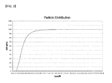
- the particle size distribution of the ceramic powder may have a D10 value of more than 0.05 ⁇ m and a D90 value of less than 3.0 ⁇ m.
- the term "specific surface area” refers to the entire surface area per unit weight, using m 2 /g as the units. Generally, when the specific surface area is large, the powder has a small particle diameter and is more porous. On the other hand, when the specific surface area is small, the powder has a large particle diameter and is less porous. Thus, the specific surface area and porosity are in inverse proportion to the particle size.
- the specific surface area of the ceramic powder is more than 15.0m 2 /g when the binder of a predetermined amount is added, the viscosity of the paste is decreased because the binder is attached to wide surfaces of the particles and binder does not remain in the solvent of the ceramic paste.
- interfacial adhesive force between the ceramic coating layer and the active material layer or adhesive force between the particles of the ceramic powder is decreased when the ceramic coating layer is coated on the active material.
- the specific surface area of the ceramic powder is less than 1.5m 2 /g when the binder of a predetermined amount is added, viscosity of the paste is increased because the binder remains in the solvent of the ceramic paste.
- the specific surface area of the ceramic powder may be selected to be more than 1.5m 2 /g and less than 15.0m 2 /g.
- the viscosity of the ceramic paste may be 20 to 3000cps. If the viscosity of the ceramic paste is less than 20cps, coating may be difficult because of the low viscosity. If the viscosity of the ceramic paste is more than 3000cps, coating may be difficult because of high viscosity.
- the particle size distribution has a D10 value of less than 0.05 ⁇ m, this indicates that many fine particles exist. If the fine particles exist in a large amount, the fine particles tend to clump with each other to form granules. Thus, it is difficult to form a uniformly dispersed paste. The viscosity of the paste is also increased because of the fine particles. In a worst case, the paste may be partially gelated over time. Granules are formed by clumping of the fine particles, and stripes are formed by the granules. Thus, the coating quality is degraded. In the worst case, when the gelated paste is coated, the thickness of the coating is uneven and many defects are generated.
- the particle size distribution of the ceramic powder may have a D10 value of more than 0.05 ⁇ m and a D90 value of less than 3.0 ⁇ m.
- the thickness distribution of the ceramic coating layer formed of the ceramic powder having the specific surface area and particle size distribution described above may be less than 10%. A smaller thickness distribution of the ceramic coating layer is more desirable. Thus, a lower limit value for the thickness distribution is not necessary.
- the ceramic powder can be coated on the electrode to uniform thickness without defects such as pin holes and cracks by controlling the specific surface area and particle size distribution of the ceramic powder. Accordingly, generation of an internal short is prevented by preventing current from being concentrated at defective portions. Thus, thermal decomposition of the active material and electrolytic solution and combustion or explosion of the secondary battery can be prevented.
- the ceramic coating layer is coated in uniform thickness.
- the electrode plates are precisely formed in desired size when the electrode plates are wound in a jelly-roll type.
- the ceramic coating layer is formed too thick, it may not be possible to insert the electrode assembly into the can or it may be necessary to apply a strong external force to the electrode assembly.
- the jelly-roll type electrode assembly may be torn or scratched by the rim of the inlet of the can.
- the electrode assembly according to aspects described above can prevent damages as described above.
- Comparison examples 1 to 16 relate to ceramic powders having small specific surface areas (not more than 1.50 m 2 /g) or large specific surface areas (not less than 15.0 m 2 /g).
- Experimental examples 1 to 16 relate to ceramic powders having specific surface areas within the range of more than 1.50 m 2 /g and less than 15.0 m 2 /g.
- ceramic pastes were prepared by mixing the ceramic powder with a binder (butyl acrylate) and a solvent (NMP), wherein the amount of the ceramic powder was 95wt%, the amount of binder was 5wt%, and the amount of solvent was 400wt% of the weight of the ceramic powder and binder.
- NMP solvent
- flowability, stability and dispersibility of each ceramic paste were measured, and then the ceramic coating layer was coated onto the active material layer of the anode plate and dried.
- the coating quality of the ceramic coating layer can be identified by thickness uniformity and formation of defects. In other words, the coating quality is good when the thickness is uniform and defects do not exist.
- Batteries were constructed according to FIGS. 2 , each having a ceramic coating layer formed by coating one of the ceramic pastes of the comparison examples or experimental examples on the both surfaces of the cathode.
- the positive active material layer 213 comprised LiCoO 2
- the negative active material layer 223 comprised graphite.
- the specific surface area of the ceramic powder was measured by ASAP2020 surface analyzer from Micromeritics Co. (USA) using N 2 gas.
- the viscosity (cps) of the ceramic paste was measured at 25 °C with a Brookfield (USA) DV-II+PRO viscometer at 50rpm by using #62 spindle.
- the measured viscosity of the ceramic paste was less than 20 cps, it was also noted that forming a coating with the ceramic paste was difficult. In such as case, the result was recorded as NG.
- Ceramic pastes having a viscosity of 20 through 3000cps were suitable for forming a coating, and ceramic pastes having a viscosity within this range were marked as OK.
- the viscosity of a ceramic paste was more than 3000 cps forming a coating was difficult, and the result was marked as NG.
- the ceramic paste was coated to a desired thickness by controlling a gap of a gap gauge. Then, the formation of ceramic paste granules was identified by the naked eye. If a stripe was formed in the coating by the presence of a granule larger than the gap of the gap gauge, the sample was marked as NG. If stripes did not exist, the sample was marked as OK.
- the thickness uniformity of the ceramic coating layer was measured after the ceramic paste was coated onto a thin copper foil base material and then dried. A sample was marked as OK when the thickness distribution was less than 10%, and marked as NG when the thickness distribution was not less than 10%.
- Pin holes, cracks, uncoated parts and stripes were defined as defects.
- a sample was marked as OK when an area of the defect was less than 5% of a normal area, and marked as NG when the area of the defect was not less than 5% of the normal area.
- the nail penetration test was conducted by overcharging the battery by 120% and penetrating the battery with a nail. Thirty batteries were tested for each example. If more than 24 batteries out of 30 did not explode, the result was marked as OK; otherwise, the result was marked as NG.
- the 150°C penetration test was conducted by charging a battery to 100%, heating the battery to 150°C at a rate of 5°C/min and then leaving the battery at 150°C for one hour. Thirty batteries were tested for each example. If more than 24 batteries out of 30 did not explode, the result was marked as OK; otherwise, the result was marked as NG.
- the bar crush test was conducted by charging a battery to 100%, placing an iron bar having a diameter of 5mm on the battery and dropping a 9kN iron mass on the iron bar from a 1m height. Thirty batteries were tested for each example. If more than 24 batteries out of 30 did not explode, the result was marked as OK; otherwise, the result was marked as NG.
- the particle size distribution of the ceramic powder was measured by an HRA model particle size distribution analyzer from Microtrack company (Japan). D10 and D90 values respectively indicate particle size distributions of relative particle contents of 10% and 90%. Measurement conditions for the viscosity of ceramic paste, layer separation, formation of granules, thickness uniformity of the ceramic coating layer and defects of the ceramic coating layer were the same as the Experiment 1.
- Comparison examples 17, 19, 21, 23, 25, 27, 29 and 31 relate to ceramic powders having a D10 particle size distribution of not more than 0.05 ⁇ m
- Comparison examples 18, 20, 22, 24, 26, 28, 30 and 32 relate to ceramic particles having a D90 particle size distribution of not less than 3 ⁇ m
- Experimental examples 17 to 32 relate to ceramic powders having a D10 value of more than 0.05 ⁇ m and a D90 value of less than 3 ⁇ m.
- Comparison examples 33 to 48 relate to ceramic powders having specific surface areas not more than 1.5 m2/g or not less than 15.0 m2/g, and particle size distribution values of D10 not more than 0.05 ⁇ m or D90 not less than 3 ⁇ m.
- Experimental examples 33 to 48 relate to ceramic powders having specific surface areas more than 1.5m2/g and less than 15m2/g, and the particle size distribution values of D10 more than 0.05 ⁇ m or D90 less than 3 ⁇ m.
- the electrode assembly and secondary battery including the electrode assembly according to aspects of the present invention produces the following effects.
- the ceramic powder can be coated onto the electrode to a uniform thickness without defects such as pin holes and cracks by controlling the specific surface area and particle size distribution of the ceramic powder.
- the ceramic coating layer is formed on the electrode in a uniform thickness without defects.
- expansion of internal short circuits can be prevented by preventing current from being concentrated at defective portions even when the separator melts to cause an internal short.
- thermal decomposition of the active material and electrolytic solution and combustion or explosion of the secondary battery can be prevented by preventing expansion of the internal short.
Landscapes
- Chemical & Material Sciences (AREA)
- Engineering & Computer Science (AREA)
- Chemical Kinetics & Catalysis (AREA)
- Electrochemistry (AREA)
- General Chemical & Material Sciences (AREA)
- Manufacturing & Machinery (AREA)
- Materials Engineering (AREA)
- Composite Materials (AREA)
- Battery Electrode And Active Subsutance (AREA)
- Cell Separators (AREA)
- Secondary Cells (AREA)
Applications Claiming Priority (1)
| Application Number | Priority Date | Filing Date | Title |
|---|---|---|---|
| KR1020080003489A KR100983161B1 (ko) | 2008-01-11 | 2008-01-11 | 전극조립체 및 이를 구비한 이차전지 |
Publications (2)
| Publication Number | Publication Date |
|---|---|
| EP2079121A1 true EP2079121A1 (de) | 2009-07-15 |
| EP2079121B1 EP2079121B1 (de) | 2019-06-05 |
Family
ID=40561755
Family Applications (1)
| Application Number | Title | Priority Date | Filing Date |
|---|---|---|---|
| EP09150049.6A Active EP2079121B1 (de) | 2008-01-11 | 2009-01-05 | Elektrodenanordnung und Sekundärbatterie damit |
Country Status (6)
| Country | Link |
|---|---|
| US (1) | US8399133B2 (de) |
| EP (1) | EP2079121B1 (de) |
| JP (1) | JP5090380B2 (de) |
| KR (1) | KR100983161B1 (de) |
| CN (1) | CN101499523A (de) |
| HU (1) | HUE045114T2 (de) |
Cited By (5)
| Publication number | Priority date | Publication date | Assignee | Title |
|---|---|---|---|---|
| US9100150B2 (en) | 2009-10-21 | 2015-08-04 | Qualcomm Incorporated | Time and frequency acquisition and tracking for OFDMA wireless systems |
| US9100843B2 (en) | 2009-11-19 | 2015-08-04 | Qualcomm Incorporated | Per-cell timing and/or frequency acquisition and their use on channel estimation in wireless networks |
| EP2784843A4 (de) * | 2012-11-30 | 2015-08-05 | Lg Chemical Ltd | Schlamm mit verbesserter dispergierbarkeit und verwendung dafür |
| EP2838140A4 (de) * | 2012-04-10 | 2015-09-09 | Lg Chemical Ltd | Elektrode mit einer porösen beschichtung, herstellungsverfahren dafür und elektrochemische vorrichtung damit |
| US9972816B2 (en) | 2008-01-29 | 2018-05-15 | Microconnect Corp. | Slurry for forming insulating layer, separator for electrochemical device, method for producing the same, and electrochemical device |
Families Citing this family (31)
| Publication number | Priority date | Publication date | Assignee | Title |
|---|---|---|---|---|
| US7749647B1 (en) * | 2009-07-17 | 2010-07-06 | Tesla Motors, Inc. | Method and apparatus for maintaining cell wall integrity during thermal runaway using a high yield strength outer sleeve |
| JP5415215B2 (ja) * | 2009-10-02 | 2014-02-12 | タテホ化学工業株式会社 | 分散性に優れる酸化マグネシウム粉末及びその製造方法 |
| KR101093916B1 (ko) * | 2009-12-15 | 2011-12-13 | 삼성에스디아이 주식회사 | 세퍼레이터, 그 제조방법 및 리튬 이차전지 |
| EP2596538B1 (de) | 2010-07-19 | 2018-12-19 | Optodot Corporation | Separatoren für batteriezellen |
| CN103035940B (zh) * | 2011-09-30 | 2016-09-07 | 深圳市比克电池有限公司 | 一种锂离子电池及其制备方法 |
| CN103035920B (zh) * | 2011-09-30 | 2016-01-20 | 深圳市比克电池有限公司 | 一种锂离子电池及其制备方法 |
| JP5614592B2 (ja) * | 2011-10-12 | 2014-10-29 | トヨタ自動車株式会社 | 二次電池用電極の製造方法 |
| TWI482340B (zh) | 2011-12-14 | 2015-04-21 | Ind Tech Res Inst | 鋰二次電池的電極模組 |
| WO2013147006A1 (ja) * | 2012-03-30 | 2013-10-03 | 日本ゼオン株式会社 | 二次電池用多孔膜、二次電池用多孔膜スラリー、非導電性粒子、二次電池用電極、二次電池用セパレータ及び二次電池 |
| WO2014017662A1 (ja) | 2012-07-27 | 2014-01-30 | 住友化学株式会社 | アルミナスラリーおよびその製造方法並びに塗工液 |
| JP6045121B2 (ja) * | 2012-11-30 | 2016-12-14 | エルジー・ケム・リミテッド | 表面特徴の異なる無機物粒子の二重多孔性コーティング層を含む二次電池用分離膜、それを含む二次電池、及び分離膜の製造方法 |
| US20140170479A1 (en) * | 2012-12-14 | 2014-06-19 | Bill Todorof | Saline battery |
| JP6370885B2 (ja) * | 2013-07-30 | 2018-08-08 | エルジー・ケム・リミテッド | 電解液との反応を防止するためのコーティング層を含む電極 |
| TWI609518B (zh) * | 2013-12-09 | 2017-12-21 | Lg化學股份有限公司 | 分散性經改善之淤漿及其用途 |
| TWI580098B (zh) | 2013-12-10 | 2017-04-21 | 財團法人工業技術研究院 | 用於鋰電池之有機-無機複合層及電極模組 |
| CN104449011A (zh) * | 2014-12-04 | 2015-03-25 | 中航锂电(洛阳)有限公司 | 一种锂离子电池绝缘涂料、制备方法及使用该绝缘涂料的极片和锂离子电池 |
| JP6415312B2 (ja) * | 2014-12-26 | 2018-10-31 | 積水化学工業株式会社 | セパレータ及び電気化学デバイス |
| CN105789537A (zh) * | 2016-03-25 | 2016-07-20 | 江苏富朗特新能源有限公司 | 锂离子电池正负极极卷外置陶瓷层组分及应用方法 |
| CN107316977A (zh) * | 2017-06-07 | 2017-11-03 | 天津市捷威动力工业有限公司 | 一种新型锂离子动力电池负极以及锂离子动力电池 |
| KR102132756B1 (ko) * | 2017-12-06 | 2020-07-13 | 주식회사 엘지화학 | 이차전지 분리막 코팅용 슬러리 조성물 및 이를 이용한 이차전지 분리막 |
| JP7047465B2 (ja) | 2018-03-02 | 2022-04-05 | 三洋電機株式会社 | 非水電解質二次電池およびその製造方法 |
| CN108649182A (zh) * | 2018-05-11 | 2018-10-12 | 江西中汽瑞华新能源科技有限公司 | 一种高安全性锂离子电池 |
| CN108878775A (zh) * | 2018-06-29 | 2018-11-23 | 桑顿新能源科技有限公司 | 一种安全补锂复合负极极片及其制备方法 |
| JP6634133B2 (ja) * | 2018-09-26 | 2020-01-22 | 積水化学工業株式会社 | セパレータ及び電気化学デバイス |
| EP3690993B1 (de) * | 2019-02-01 | 2023-10-04 | Samsung SDI Co., Ltd. | Zusammensetzungen zur herstellung einer porösen isolierschicht, elektrode für eine wiederaufladbare batterie mit nichtwässrigem elektrolyt, wiederaufladbare batterie mit der elektrode und verfahren zur herstellung der elektrode |
| CN110957464B (zh) * | 2019-09-25 | 2021-08-17 | 东莞赣锋电子有限公司 | 一种涂覆极片的制备方法 |
| CA3072784A1 (fr) * | 2020-02-14 | 2021-08-14 | Hydro-Quebec | Electrodes a surface modifiee, procedes de preparation, et utilisations dans des cellules electrochimiques |
| EP4254636A4 (de) * | 2021-08-27 | 2025-06-18 | LG Energy Solution, Ltd. | Separator für elektrochemische vorrichtung sowie elektrodenanordnung und elektrochemische vorrichtung damit |
| EP4573621A1 (de) * | 2022-08-19 | 2025-06-25 | Techtronic Cordless GP | Lithium-ionen-batterie ohne trennelement |
| KR102904505B1 (ko) * | 2023-01-30 | 2025-12-24 | 삼성에스디아이 주식회사 | 전극조립체 및 이를 포함하는 이차전지 |
| CN118825547B (zh) * | 2024-06-19 | 2025-12-26 | 广东碳语新材料有限公司 | 一种高耐热高粘接复合浆料及其制备方法和应用 |
Citations (9)
| Publication number | Priority date | Publication date | Assignee | Title |
|---|---|---|---|---|
| JP2001110454A (ja) | 1999-10-08 | 2001-04-20 | Matsushita Electric Ind Co Ltd | リチウムイオン二次電池 |
| EP1146576A1 (de) * | 2000-04-10 | 2001-10-17 | Celgard Inc. | Separator für wiederaufladbare Lithiumbatterie hoher Energiedichte |
| EP1667254A1 (de) | 2004-11-17 | 2006-06-07 | Samsung SDI Co., Ltd. | Separator zur Verwendung in einer Lithiumionensekundärbatterie |
| US20060246355A1 (en) * | 2005-04-27 | 2006-11-02 | Samsung Sdi Co., Ltd. | Lithium secondary battery |
| US20080241674A1 (en) * | 2007-03-29 | 2008-10-02 | Jinhee Kim | Electrode assembly and secondary battery including electrode assembly |
| EP1998391A2 (de) * | 2007-05-29 | 2008-12-03 | Samsung SDI Co., Ltd. | Lithium Sekundärbatterie |
| EP1998401A2 (de) * | 2007-05-25 | 2008-12-03 | Samsung SDI Co., Ltd. | Elektrodenanordnung und Sekundärbatterie damit |
| US20080299461A1 (en) * | 2007-06-01 | 2008-12-04 | Jinhee Kim | Secondary battery including positive electrode or negative electrode coated with a ceramic coating portion |
| EP2048736A1 (de) * | 2007-10-09 | 2009-04-15 | Samsung SDI Co., Ltd. | Lithium-Sekundärbatterie |
Family Cites Families (13)
| Publication number | Priority date | Publication date | Assignee | Title |
|---|---|---|---|---|
| US6001761A (en) | 1994-09-27 | 1999-12-14 | Nippon Shokubai Co., Ltd. | Ceramics sheet and production method for same |
| JP3359164B2 (ja) | 1994-10-19 | 2002-12-24 | キヤノン株式会社 | 二次電池 |
| US5914094A (en) * | 1995-12-19 | 1999-06-22 | Samsung Display Devices Co., Ltd. | Process for preparing cathode active material by a sol-gel method |
| JPH10223195A (ja) | 1997-02-03 | 1998-08-21 | Asahi Chem Ind Co Ltd | 新規な電池 |
| US6773847B2 (en) | 2000-06-07 | 2004-08-10 | Gs-Melcotec Co., Ltd. | Battery |
| DE10238941B4 (de) | 2002-08-24 | 2013-03-28 | Evonik Degussa Gmbh | Elektrischer Separator, Verfahren zu dessen Herstellung und Verwendung in Lithium-Hochleistungsbatterien sowie eine den Separator aufweisende Batterie |
| WO2005029614A1 (ja) | 2003-09-18 | 2005-03-31 | Matsushita Electric Industrial Co., Ltd. | リチウムイオン二次電池 |
| WO2005098997A1 (ja) * | 2004-03-30 | 2005-10-20 | Matsushita Electric Industrial Co., Ltd. | 非水電解液二次電池 |
| JP5061417B2 (ja) * | 2004-04-23 | 2012-10-31 | パナソニック株式会社 | リチウムイオン二次電池 |
| JP4763253B2 (ja) | 2004-05-17 | 2011-08-31 | パナソニック株式会社 | リチウムイオン二次電池 |
| JP4184404B2 (ja) | 2005-12-08 | 2008-11-19 | 日立マクセル株式会社 | 電気化学素子用セパレータおよび電気化学素子 |
| JP5055865B2 (ja) | 2006-07-19 | 2012-10-24 | パナソニック株式会社 | リチウムイオン二次電池 |
| KR100778975B1 (ko) | 2007-03-08 | 2007-11-28 | 삼성에스디아이 주식회사 | 리튬 이차 전지 |
-
2008
- 2008-01-11 KR KR1020080003489A patent/KR100983161B1/ko active Active
- 2008-12-18 US US12/338,145 patent/US8399133B2/en active Active
-
2009
- 2009-01-05 HU HUE09150049A patent/HUE045114T2/hu unknown
- 2009-01-05 EP EP09150049.6A patent/EP2079121B1/de active Active
- 2009-01-06 CN CNA2009100003507A patent/CN101499523A/zh active Pending
- 2009-01-13 JP JP2009004716A patent/JP5090380B2/ja active Active
Patent Citations (9)
| Publication number | Priority date | Publication date | Assignee | Title |
|---|---|---|---|---|
| JP2001110454A (ja) | 1999-10-08 | 2001-04-20 | Matsushita Electric Ind Co Ltd | リチウムイオン二次電池 |
| EP1146576A1 (de) * | 2000-04-10 | 2001-10-17 | Celgard Inc. | Separator für wiederaufladbare Lithiumbatterie hoher Energiedichte |
| EP1667254A1 (de) | 2004-11-17 | 2006-06-07 | Samsung SDI Co., Ltd. | Separator zur Verwendung in einer Lithiumionensekundärbatterie |
| US20060246355A1 (en) * | 2005-04-27 | 2006-11-02 | Samsung Sdi Co., Ltd. | Lithium secondary battery |
| US20080241674A1 (en) * | 2007-03-29 | 2008-10-02 | Jinhee Kim | Electrode assembly and secondary battery including electrode assembly |
| EP1998401A2 (de) * | 2007-05-25 | 2008-12-03 | Samsung SDI Co., Ltd. | Elektrodenanordnung und Sekundärbatterie damit |
| EP1998391A2 (de) * | 2007-05-29 | 2008-12-03 | Samsung SDI Co., Ltd. | Lithium Sekundärbatterie |
| US20080299461A1 (en) * | 2007-06-01 | 2008-12-04 | Jinhee Kim | Secondary battery including positive electrode or negative electrode coated with a ceramic coating portion |
| EP2048736A1 (de) * | 2007-10-09 | 2009-04-15 | Samsung SDI Co., Ltd. | Lithium-Sekundärbatterie |
Cited By (8)
| Publication number | Priority date | Publication date | Assignee | Title |
|---|---|---|---|---|
| US9972816B2 (en) | 2008-01-29 | 2018-05-15 | Microconnect Corp. | Slurry for forming insulating layer, separator for electrochemical device, method for producing the same, and electrochemical device |
| US9100150B2 (en) | 2009-10-21 | 2015-08-04 | Qualcomm Incorporated | Time and frequency acquisition and tracking for OFDMA wireless systems |
| US9401784B2 (en) | 2009-10-21 | 2016-07-26 | Qualcomm Incorporated | Time and frequency acquisition and tracking for OFDMA wireless systems |
| US9628228B2 (en) | 2009-10-21 | 2017-04-18 | Qualcomm Incorporated | Time and frequency acquisition and tracking for OFDMA wireless systems |
| US9100843B2 (en) | 2009-11-19 | 2015-08-04 | Qualcomm Incorporated | Per-cell timing and/or frequency acquisition and their use on channel estimation in wireless networks |
| US10111111B2 (en) | 2009-11-19 | 2018-10-23 | Qualcomm Incorporated | Per-cell timing and/or frequency acquisition and their use on channel estimation in wireless networks |
| EP2838140A4 (de) * | 2012-04-10 | 2015-09-09 | Lg Chemical Ltd | Elektrode mit einer porösen beschichtung, herstellungsverfahren dafür und elektrochemische vorrichtung damit |
| EP2784843A4 (de) * | 2012-11-30 | 2015-08-05 | Lg Chemical Ltd | Schlamm mit verbesserter dispergierbarkeit und verwendung dafür |
Also Published As
| Publication number | Publication date |
|---|---|
| JP5090380B2 (ja) | 2012-12-05 |
| CN101499523A (zh) | 2009-08-05 |
| JP2009170421A (ja) | 2009-07-30 |
| KR100983161B1 (ko) | 2010-09-20 |
| KR20090077502A (ko) | 2009-07-15 |
| HUE045114T2 (hu) | 2019-12-30 |
| US20090181300A1 (en) | 2009-07-16 |
| US8399133B2 (en) | 2013-03-19 |
| EP2079121B1 (de) | 2019-06-05 |
Similar Documents
| Publication | Publication Date | Title |
|---|---|---|
| EP2079121B1 (de) | Elektrodenanordnung und Sekundärbatterie damit | |
| US7758998B2 (en) | Lithium ion secondary battery | |
| US12555778B2 (en) | Negative electrode plate and lithium-ion battery | |
| KR100732803B1 (ko) | 리튬이온 2차전지 | |
| KR100450109B1 (ko) | 비수계 이차전지와 그 제조법 | |
| CN101796668B (zh) | 电池用隔膜及非水电解液电池 | |
| EP2048734B1 (de) | Elektrodenanordnung und Sekundärbatterie | |
| US20140023908A1 (en) | Lithium-ion secondary battery | |
| US10014505B2 (en) | Separator having high heat resistance, manufacturing method thereof and secondary battery including the separator | |
| WO2005112180A1 (ja) | リチウムイオン二次電池 | |
| CN101276895A (zh) | 锂离子二次电池多孔隔膜层用组合物及锂离子二次电池 | |
| US8349482B2 (en) | Electrode assembly and secondary battery with the same | |
| KR100992248B1 (ko) | 리튬이온 이차전지용 전극 | |
| KR20160061167A (ko) | 무기물층이 코팅된 전극, 그 제조 방법 및 이를 구비한 이차 전지 | |
| US20090208838A1 (en) | Electrode assembly and secondary battery having the same | |
| US20080206645A1 (en) | Non-aqueous electrolyte secondary battery and method for producing same | |
| CN100492720C (zh) | 锂离子二次电池 | |
| KR20140015841A (ko) | 이중 코팅층이 형성된 전극을 포함하는 리튬이차전지 | |
| JPH09265990A (ja) | 非水電解液電池及びその製造方法 | |
| KR20080066234A (ko) | 전극 조립체와 이를 구비하는 이차 전지 및 그 제조 방법 | |
| CN116454539A (zh) | 一种电池和用电设备 | |
| KR100749626B1 (ko) | 이차전지 | |
| KR101308195B1 (ko) | 전극조립체와 이를 포함하는 리튬 이차전지 및 리튬이차전지의 제조방법 | |
| CN115832610A (zh) | 一种功能化的锂电池隔膜及其制备方法和应用 | |
| KR101438696B1 (ko) | 전극조립체 및 이를 구비하는 이차전지 |
Legal Events
| Date | Code | Title | Description |
|---|---|---|---|
| PUAI | Public reference made under article 153(3) epc to a published international application that has entered the european phase |
Free format text: ORIGINAL CODE: 0009012 |
|
| 17P | Request for examination filed |
Effective date: 20090105 |
|
| AK | Designated contracting states |
Kind code of ref document: A1 Designated state(s): AT BE BG CH CY CZ DE DK EE ES FI FR GB GR HR HU IE IS IT LI LT LU LV MC MK MT NL NO PL PT RO SE SI SK TR |
|
| AX | Request for extension of the european patent |
Extension state: AL BA RS |
|
| AKX | Designation fees paid |
Designated state(s): DE FR GB HU |
|
| STAA | Information on the status of an ep patent application or granted ep patent |
Free format text: STATUS: EXAMINATION IS IN PROGRESS |
|
| 17Q | First examination report despatched |
Effective date: 20170215 |
|
| GRAJ | Information related to disapproval of communication of intention to grant by the applicant or resumption of examination proceedings by the epo deleted |
Free format text: ORIGINAL CODE: EPIDOSDIGR1 |
|
| GRAP | Despatch of communication of intention to grant a patent |
Free format text: ORIGINAL CODE: EPIDOSNIGR1 |
|
| GRAP | Despatch of communication of intention to grant a patent |
Free format text: ORIGINAL CODE: EPIDOSNIGR1 |
|
| STAA | Information on the status of an ep patent application or granted ep patent |
Free format text: STATUS: GRANT OF PATENT IS INTENDED |
|
| INTG | Intention to grant announced |
Effective date: 20190220 |
|
| GRAS | Grant fee paid |
Free format text: ORIGINAL CODE: EPIDOSNIGR3 |
|
| GRAA | (expected) grant |
Free format text: ORIGINAL CODE: 0009210 |
|
| STAA | Information on the status of an ep patent application or granted ep patent |
Free format text: STATUS: THE PATENT HAS BEEN GRANTED |
|
| AK | Designated contracting states |
Kind code of ref document: B1 Designated state(s): DE FR GB HU |
|
| REG | Reference to a national code |
Ref country code: GB Ref legal event code: FG4D |
|
| REG | Reference to a national code |
Ref country code: DE Ref legal event code: R096 Ref document number: 602009058593 Country of ref document: DE |
|
| REG | Reference to a national code |
Ref country code: HU Ref legal event code: AG4A Ref document number: E045114 Country of ref document: HU |
|
| REG | Reference to a national code |
Ref country code: DE Ref legal event code: R097 Ref document number: 602009058593 Country of ref document: DE |
|
| PLBE | No opposition filed within time limit |
Free format text: ORIGINAL CODE: 0009261 |
|
| STAA | Information on the status of an ep patent application or granted ep patent |
Free format text: STATUS: NO OPPOSITION FILED WITHIN TIME LIMIT |
|
| 26N | No opposition filed |
Effective date: 20200306 |
|
| REG | Reference to a national code |
Ref country code: DE Ref legal event code: R079 Ref document number: 602009058593 Country of ref document: DE Free format text: PREVIOUS MAIN CLASS: H01M0002160000 Ipc: H01M0050409000 |
|
| P01 | Opt-out of the competence of the unified patent court (upc) registered |
Effective date: 20230528 |
|
| PGFP | Annual fee paid to national office [announced via postgrant information from national office to epo] |
Ref country code: FR Payment date: 20251231 Year of fee payment: 18 |
|
| PGFP | Annual fee paid to national office [announced via postgrant information from national office to epo] |
Ref country code: HU Payment date: 20260130 Year of fee payment: 18 |
|
| PGFP | Annual fee paid to national office [announced via postgrant information from national office to epo] |
Ref country code: GB Payment date: 20260106 Year of fee payment: 18 |
|
| PGFP | Annual fee paid to national office [announced via postgrant information from national office to epo] |
Ref country code: DE Payment date: 20251230 Year of fee payment: 18 |