EP2075552B1 - Tintenstrahldrucker mit tintenflussgeschwindigkeitsmessgerät - Google Patents
Tintenstrahldrucker mit tintenflussgeschwindigkeitsmessgerät Download PDFInfo
- Publication number
- EP2075552B1 EP2075552B1 EP08022323A EP08022323A EP2075552B1 EP 2075552 B1 EP2075552 B1 EP 2075552B1 EP 08022323 A EP08022323 A EP 08022323A EP 08022323 A EP08022323 A EP 08022323A EP 2075552 B1 EP2075552 B1 EP 2075552B1
- Authority
- EP
- European Patent Office
- Prior art keywords
- light
- ink
- section
- emitting
- flow
- Prior art date
- Legal status (The legal status is an assumption and is not a legal conclusion. Google has not performed a legal analysis and makes no representation as to the accuracy of the status listed.)
- Ceased
Links
Images


Classifications
-
- G—PHYSICS
- G01—MEASURING; TESTING
- G01F—MEASURING VOLUME, VOLUME FLOW, MASS FLOW OR LIQUID LEVEL; METERING BY VOLUME
- G01F1/00—Measuring the volume flow or mass flow of fluid or fluent solid material wherein the fluid passes through a meter in a continuous flow
- G01F1/05—Measuring the volume flow or mass flow of fluid or fluent solid material wherein the fluid passes through a meter in a continuous flow by using mechanical effects
- G01F1/20—Measuring the volume flow or mass flow of fluid or fluent solid material wherein the fluid passes through a meter in a continuous flow by using mechanical effects by detection of dynamic effects of the flow
- G01F1/28—Measuring the volume flow or mass flow of fluid or fluent solid material wherein the fluid passes through a meter in a continuous flow by using mechanical effects by detection of dynamic effects of the flow by drag-force, e.g. vane type or impact flowmeter
-
- B—PERFORMING OPERATIONS; TRANSPORTING
- B41—PRINTING; LINING MACHINES; TYPEWRITERS; STAMPS
- B41J—TYPEWRITERS; SELECTIVE PRINTING MECHANISMS, i.e. MECHANISMS PRINTING OTHERWISE THAN FROM A FORME; CORRECTION OF TYPOGRAPHICAL ERRORS
- B41J2/00—Typewriters or selective printing mechanisms characterised by the printing or marking process for which they are designed
- B41J2/005—Typewriters or selective printing mechanisms characterised by the printing or marking process for which they are designed characterised by bringing liquid or particles selectively into contact with a printing material
- B41J2/01—Ink jet
- B41J2/17—Ink jet characterised by ink handling
- B41J2/175—Ink supply systems ; Circuit parts therefor
-
- G—PHYSICS
- G01—MEASURING; TESTING
- G01L—MEASURING FORCE, STRESS, TORQUE, WORK, MECHANICAL POWER, MECHANICAL EFFICIENCY, OR FLUID PRESSURE
- G01L1/00—Measuring force or stress, in general
- G01L1/04—Measuring force or stress, in general by measuring elastic deformation of gauges, e.g. of springs
- G01L1/044—Measuring force or stress, in general by measuring elastic deformation of gauges, e.g. of springs of leaf springs
-
- G—PHYSICS
- G01—MEASURING; TESTING
- G01L—MEASURING FORCE, STRESS, TORQUE, WORK, MECHANICAL POWER, MECHANICAL EFFICIENCY, OR FLUID PRESSURE
- G01L1/00—Measuring force or stress, in general
- G01L1/24—Measuring force or stress, in general by measuring variations of optical properties of material when it is stressed, e.g. by photoelastic stress analysis using infrared, visible light, ultraviolet
-
- G—PHYSICS
- G01—MEASURING; TESTING
- G01L—MEASURING FORCE, STRESS, TORQUE, WORK, MECHANICAL POWER, MECHANICAL EFFICIENCY, OR FLUID PRESSURE
- G01L1/00—Measuring force or stress, in general
- G01L1/26—Auxiliary measures taken, or devices used, in connection with the measurement of force, e.g. for preventing influence of transverse components of force, for preventing overload
Definitions
- the present invention relates to an ink-jet printer which is provided with a flow velocity detector.
- a flow rate meter which is based on the Pitot tube system
- the flow rate meter flow velocity meter
- the flow rate meter including a Pitot tube which is arranged in a gas flow of a gas to be measured, a differential pressure detector which detects the differential pressure between the total pressure in a total pressure-detecting tube of the Pitot tube and the static pressure in a static pressure-detecting tube, and a calculating means which calculates the flow velocity of the gas in accordance with a detection output of the differential pressure detector (see Japanese Patent Application Laid-open No. JP-2004-294147 ).
- An ultrasonic flow rate meter is known as another example of the flow rate meter.
- an ultrasonic flow rate meter is known, wherein an ultrasonic wave signal, which is generated by an ultrasonic vibrator disposed on the upstream side of a tube passage, is received by an ultrasonic vibrator disposed on the downstream side, and an ultrasonic wave signal, which is generated by the ultrasonic vibrator disposed on the downstream side, is received by the ultrasonic vibrator disposed on the upstream side.
- Two pieces of digital data which are obtained by sampling the signals respectively, are determined, and then the total sum of differences between two signal arrays is determined in a calculating unit while deviating the time axes of the pieces of data.
- the transmission time difference is determined in CPU on the basis of the point at which the total sum of the differences is minimized to determine the flow velocity of the fluid (see Japanese Patent Application Laid-open No. JP-2007-298347 ).
- An ultrasonic Doppler flow rate meter is known as still another example of the flow velocity meter.
- an ultrasonic Doppler flow rate meter is known, which measures the flow rate of the fluid allowed to naturally flow downwardly in a tube passage in accordance with the following procedure.
- an ultrasonic wave having a constant frequency is transmitted at an angle of elevation in the flow direction from a transmitting element provided at a central portion of the bottom of the tube passage.
- An emission wave is received by a receiving element to obtain a beat waveform including the information of a Doppler shift frequency by means of a heterodyne detecting section.
- the signal except for the noise is allowed to pass by means of a bandpass filter, and the AD conversion is performed by means of an AD converter.
- a frequency spectrum of the beat waveform is determined by means of a high speed Fourier transformation section.
- a peak frequency in the frequency spectrum is determined by means of a peak detecting section.
- the average flow velocity and the flow rate are calculated on the basis of the peak frequency by means of a flow rate calculating section.
- JP-2004-170308 A discloses a pressure sensitive device comprising a flow passage-forming section which defines a flow passage; a stress light-emitting section arranged at the flow passage-forming section to receive a stress having a magnitude depending on the fluid pressure and which emits a light of which amount corresponds to a change caused by the received stress; and a light-receiving sensor which receives the light emitted by the stress light-emitting section, wherein a fluid pressure is detected based on an amount of the light received by the light-receiving sensor to generate a detection signal.
- the present invention has been made in order to solve the problems as described above, the object of which is to provide an ink-jet printer which is provided with a flow velocity detector which has a simple structure, which is small-sized, and which is provided at low cost. This object is achieved by the ink-jet printer having the features of claim 1.
- the stress light-emitting section when the ink flows through the flow passage, the stress light-emitting section receives the stress having the magnitude depending on the flow velocity of the ink. Therefore, the light is emitted at the luminance corresponding to the change of the received stress.
- the light-receiving sensor is capable of detecting the flow velocity of the ink by receiving the light emitted by the stress light-emitting section to generate the detection signal. Accordingly, it is possible to detect or sense the fact that the ink is allowed to flow through the flow passage.
- the flow velocity detector of the ink-jet printer according to the present invention may further include a deformation-facilitating structure which is formed on the flow passage-forming section and which is deformable at a magnitude depending on the flow velocity of the ink, and the deformation-facilitating structure may be provided with the stress light-emitting section.
- the deformation-facilitating structure when the ink flows through the flow passage, the deformation-facilitating structure is deformed at the magnitude corresponding to the flow velocity of the ink.
- the stress light-emitting section is deformed in accordance with the deformation of the deformation-facilitating structure to emit the light.
- the deformation-facilitating structure makes it possible to obtain the relatively large deformation even when the flow velocity of the ink is relatively small.
- the relatively large deformation can be applied to the stress light-emitting section. Therefore, it is possible to detect the relatively small flow velocity by means of the flow velocity detector of the ink-jet printer.
- the deformation-facilitating structure may have a protrusion which protrudes into the flow passage, or a thin-walled section or a low rigidity section which is formed in the flow passage-forming section.
- the projection, the thin-walled section, or the low rigidity section can be formed to be deformable at the necessary magnitude corresponding to the flow velocity of the ink allowed to flow through the flow passage.
- the stress light-emitting section is deformed in accordance with the deformation of the projection or the like. Therefore, the stress light-emitting section is successfully allowed to emit the light at the required luminance.
- a part of the flow passage-forming section, through which the light is transmitted may be formed of a light-transmissive material such that the light emitted by the stress light-emitting section arrives at the light-receiving sensor.
- the light-receiving sensor when the stress light-emitting section emits the light in accordance with the flow of the ink through the flow passage, the light can arrive at the light-receiving sensor by being transmitted through the predetermined route formed of the light-transmissive material and/or through the space in some cases.
- the route (flow passage-forming section), through which the light is transmitted is formed of the light-transmissive material so that the light, which is emitted by the stress light-emitting section, arrives at the light-receiving sensor. Accordingly, the light-receiving sensor can receive the light emitted by the stress light-emitting section.
- the ink-jet printer is capable of detecting the flow velocity of the ink. Therefore, for example, when the purge operation is performed to discharge the ink from nozzles of an ink-jet head as the maintenance for the ink-jet printer, it is possible to check whether or not the ink is discharged from the nozzles.
- the flow passage may be formed as a plurality of flow passages, and the flow passage-forming section may have a plurality of individual flow passage-forming sections each of which defines one of the flow passages;
- the stress light-emitting section may include a plurality of individual stress light-emitting sections each of which is arranged at one of the individual flow passage-forming sections;
- the light-receiving sensor may include a single light-receiving sensor; and the flow velocity detector may successively receive lights emitted from the respective individual stress light-emitting sections by the single light-receiving sensor to detect flow velocity of the ink in each of the flow passages.
- the single light-receiving sensor can be used to successively receive the lights emitted by the plurality of stress light-emitting sections provided for the respective flow passage-forming sections for forming the plurality of fluid flow passages. Accordingly, it is possible to detect the flow velocities of the inks contained in the respective flow passages. As described above, it is enough to provide one light-receiving sensor. Therefore, it is possible to simplify the structure of the printer, and it is possible to decrease the cost.
- the ink-jet printer according to the present invention may further include a movable section which movably supports the plurality of individual flow passage-forming sections having the individual stress light-emitting sections arranged therein, wherein the single light-receiving sensor may be fixed at a predetermined position; and the movable section may be moved so that the lights successively emitted by the plurality of individual stress light-emitting sections are successively received by the single light-receiving sensor and that the flow velocity of the ink in each of the respective flow passages is detected.
- the movable section When the flow velocities of the inks contained in the plurality of flow passages are detected respectively by means of the flow velocity detector, then the movable section is moved, and the lights, which are emitted from the plurality of stress light-emitting sections respectively, can be successively received by the one light-receiving sensor fixed to the fixed section. Accordingly, it is possible to detect the flow velocities of the inks contained in the respective flow passages.
- the movable section is, for example, a carriage on which the ink-jet head based on the serial system is provided, it is unnecessary to provide any exclusive moving mechanism for moving the movable section. Accordingly, it is possible to simplify the structure of the printer, and it is possible to lower the cost.
- the stress light-emitting section which is provided in the flow passage, receives the stress of the magnitude corresponding to the flow velocity of the ink.
- the light is emitted at the luminance corresponding to the change of the received stress.
- the flow velocity of the ink is detected by receiving the light by means of the light-receiving sensor. Therefore, the structure is simple and small-sized. It is possible to detect the flow velocity of the ink at the low cost.
- the ink-jet printer concerning the present invention, it is possible to detect the flow velocity of the ink. Therefore, for example, when the purge operation is performed to discharge the ink from the nozzles of the ink-jet head, it is possible to check whether or not the ink is discharged from the nozzles. Accordingly, it is possible to avoid any erroneous printing which would be otherwise caused by the fact that the ink is not discharged from the nozzles.
- an ink-jet printer 11 performs the printing such that inks 15, which are formed into minute droplets, are allowed to blow against a recording medium 12 such as the printing paper.
- a flow velocity detector 13 which is provided for the ink-jet printer 11, detects the flow velocity brought about when the ink 15 is allowed to flow through each of first to fourth ink flow passages 14a to 14d shown in Fig. 10 .
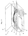
- the first to fourth ink flow passages 14a to 14d are communicated with a large number of nozzles (not shown) which are provided on the lower surface of a head unit 16 shown in Fig. 9 .
- Fig. 10 shows a magnified plan view illustrating the head unit 16.
- the purpose of detecting or sensing the flow velocity of the ink 15 is to check whether or not the ink 15 is discharged from the nozzles, for example, when the purge operation is performed to discharge the ink 15 from the nozzles of the ink-jet head 17 as the maintenance for the ink-jet printer 11.
- Fig. 8 shows a perspective view illustrating the appearance of the ink-jet printer 11
- Fig. 9 shows a perspective view illustrating a state in which a lid member 18 of the ink-jet printer 11 is open.
- a guide rail 19 is arranged substantially horizontally in the ink-jet printer (liquid droplet discharge apparatus) 11.
- the head unit 16 is supported by the guide rail 19 by the aid of a carriage (not shown) so that the head unit 16 is slidable in the scanning direction along the guide rail 19.
- the head unit 16 is connected to a rotary shaft of a motor by the aid of unillustrated pulleys and a timing belt. When the motor is driven and rotated in the forward or reverse direction, the head unit 16 is subjected to the reciprocating scanning along the guide rail 19.
- FIG. 9 As shown in Fig. 9 , four flexible ink supply tubes 21, which supply the four color inks (black, cyan, magenta, and yellow) from four ink cartridges (liquid supply sources) 20 installed to a cartridge installing section respectively, are connected to the head unit 16. Further, an ink-jet head 17 is carried on the head unit 16. The ink-jet head 17 discharges the inks (liquid droplets) 15 from the plurality of nozzles toward the surface of the recording medium 12 such as the printing paper to be transported in the predetermined paper feed direction perpendicular to the scanning direction therebelow.
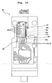
- the flow velocity detector 13 includes first to fourth projections 23 each of which serves as a deformation-facilitating structure (a structure which is susceptible to deform) provided to protrude on the inner surface of one of the flow passage-forming sections (individual flow passage-forming sections) 22 for forming one of the first to fourth ink flow passages (individual flow passages) 14a to 14d, stress light-emitting sections (individual stress light-emitting sections) 24 each of which is provided on the surface of one of the first to fourth projections 23, and one light-receiving sensor 25 which receives the light emitted from each of the stress light-emitting sections 24.
- Fig. 1A shows the first ink flow passage 14a.
- the first to fourth ink flow passages 14a to 14d are provided on the upper surface portions of the head unit 16.
- the first to fourth projections 23, which protrude toward the inside of the flow passages respectively, are provided one by one at predetermined positions for the first to fourth ink flow passages 14a to 14d.
- One end or first end of each of the first to fourth ink flow passages 14a to 14d provided for the head unit 16 is formed as an ink inlet port 26.
- One end of each of ink supply tubes 21, which corresponds to each of the ink inlet ports 26, is connected to each of the ink inlet ports 26.
- each of the first to fourth ink flow passages 14a to 14d is communicated with a plurality of nozzle holes which are provided on the lower surface of the ink-jet head 17 carried on the head unit 16 and which correspond to each of the first to fourth ink flow passages 14a to 14d.
- the light-receiving sensor 25 is provided fixedly on the inner surface of the side wall of a body 27 of the ink-jet printer 11.
- a light-receiving section 25a which is provided on the lower surface of the light-receiving sensor 25, is positioned at each of the positions disposed over or above each of the first to fourth projections 23 arranged for the four respective first to fourth ink flow passages 14a to 14d as shown in Fig. 10 .
- first maintenance position when the flow velocity of the ink 15 contained in the first ink flow passage 14a disposed at the right end, the head unit 16 is moved so that the first projection 23, which is arranged in the first ink flow passage 14a, is positioned under or below the light-receiving section 25a of the light-receiving sensor 25.
- first maintenance position The position of the head unit 16, which is provided in this situation, is referred to as "first maintenance position".
- the head unit 16 is moved so that corresponding one of the second to fourth projections 23, which is arranged in the one of the second to fourth ink flow passages 14b to 14d, is positioned under or below the light-receiving section 25a of the light-receiving sensor 25.
- the positions of the head unit 16, which are provided in these situations, are referred to as "second to fourth maintenance positions" respectively (not shown).
- the flow passage-forming sections 22, which form the first to fourth ink flow passages 14a to 14d, are formed of a synthetic resin having the light-transmissive property. Therefore, the lights, which are emitted from the stress light-emitting sections 24 provided on the surfaces of the first to fourth projections 23 arranged in the first to fourth ink flow passages 14a to 14d respectively, are capable of arriving at the light-receiving sensor 25.
- the first to fourth ink flow passages 14a to 14d shown in Fig. 10 are equivalent components, and the first to fourth projections 23 provided with the stress light-emitting sections 24 arranged in the first to fourth ink flow passages 14a to 14d respectively are also equivalent components.
- the following explanation will be made about the first ink flow passage 14a and the first projection 23 provided with the stress light-emitting section 24. Any explanation will be omitted about the second to fourth ink flow passages 14b to 14d and the second to fourth projections 23 provided with the stress light-emitting sections 24.
- Fig. 1A shows a sectional view as obtained when the flow passage-forming section 22 for forming the first ink flow passage 14a is cut in the direction parallel to the flow passage direction.
- Fig. 1B shows a vertical sectional view illustrating the flow passage-forming section 22 provided with the first projection 23 shown in Fig. 1A .
- the first ink flow passage 14a has a circular vertical cross-sectional shape, which is formed by the flow passage-forming section 22.
- the first projection 23 is the deformation-facilitating structure.
- the deformation-facilitating structure herein means a structure which is greatly deformed when the stress is applied.
- the first projection 23 is deformed so that the first projection 23 is flexibly warped or bent to a great extent in the direction of the flow of the ink.
- the first projection 23 is formed to have a cantilever support structure on the inner surface of the cylindrical flow passage-forming section 22 which forms the first ink flow passage 14a.
- the first projection 23 is formed to have a length extending from the portion which is closest to the light-receiving sensor 25 to the position which is slightly short of the central position of the first ink flow passage 14a.
- the first projection 23 is a substantially trapezoidal shaped plate member which is tapered at positions nearer to the forward end.
- the plate surface thereof is perpendicular to the extending direction of the first ink flow passage 14a (see Fig. 1B ).
- the thickness of the first projection 23 is also tapered at positions nearer to the forward end.
- the first projection 23 has a proximal end portion 123a which is joined to the wall surface of the first ink flow passage 14a, and an extending portion 123b which extends toward the inside of the first ink flow passage 14a in the plane perpendicular to the flow direction of the ink in the first ink flow passage 14a from the proximal end portion 123a.
- the thickness (length in the direction of the flow of the ink) and the width of the extending portion 123b are smaller than the thickness and the width of the proximal end portion 123a, respectively.
- the first projection 23 is arranged so that the plate surface is perpendicular to the direction of the first ink flow passage 14a.
- the first projection 23 behaves as the resistance to the flow of the ink 15 in the first ink flow passage 14a to provide a relatively large flexure or warpage.
- the reason, why the first projection 23 behaves as the resistance to the flow of the ink 15 to provide the relatively large flexure, is that it is intended to apply a relatively large stress to the stress light-emitting section 24 provided on the plate surface of the first projection 23 so that the luminance (intensity) of the light emitted by the stress light-emitting section 24 is increased.
- the stress light-emitting section 24 is secured to the plate surface of the first projection 23, for example, by means of the application or coating to provide a predetermined thickness.
- the plate surface of the first projection 23, to which the stress light-emitting section 24 is secured, is the surface disposed on the side on which the ink 15 allowed to flow through the first ink flow passage 14a is allowed to collide therewith.
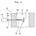
- the first projection 23 which is provided with the stress light-emitting section 24, is used, as shown in Fig. 2 , the first projection 23 is warped and deformed in the flow direction of the ink 15 at a magnitude corresponding to the flow velocity of the ink 15.
- the stress light-emitting section 24 receives the stress of the magnitude corresponding to the flow velocity of the ink 15, and the stress light-emitting section 24 emits the light at a luminance (intensity) corresponding to the change of the received stress.
- the luminance of the stress light-emitting section 24 is changed in correlation with the amount of change of the stress per unit time (stress velocity).
- the stress light-emitting section 24 in order to allow the stress light-emitting section 24 to emit the light at the high luminance, it is appropriate that the magnitude of the stress applied to the stress light-emitting section 24 is greatly changed in a short period of time.
- the arrow 28 shown in Fig. 2 indicates the light emitted by the stress light-emitting section 24.
- the arrow 29 indicates the flow direction of the ink 15.
- the light which is emitted by each of the stress light-emitting sections 24 provided on the surfaces of the second to fourth projections 23 arranged in the second to fourth ink flow passages 14a to 14d respectively, is transmitted through each of the flow passage-forming sections 22 having the light-transmissive property at each of different timings, and the light 23 is received by the light-receiving sensor 25.
- the head unit 16 is successively moved from the first maintenance position to the second, third, and fourth maintenance positions, and thus the flow velocities of the inks 15 contained in the first to fourth ink flow passages 14a to 14d can be detected or sensed by using one light-receiving sensor 25.
- the ink-jet printer 11 further includes a calculation control section (not shown).
- the calculation control section includes, for example, a central processing unit (CPU), which functions as a judging section as described later on.
- the light-receiving sensor 25 is electrically connected to the calculation control section.
- the judging section judges whether or not the light-receiving sensor 25 outputs the detection signal.
- the light-receiving sensor 25 outputs the detection signal when the light-receiving sensor 25 receives the light 28 of not less than the predetermined luminance (intensity) emitted by each of the stress light-emitting sections 24 provided on each of the surfaces of the first to fourth projections 23.
- the judging section when the luminance (intensity) of the light 28 emitted by a certain stress light-emitting section 24 is not less than the predetermined value, i.e., when the judging section judges that the light-receiving sensor 25 outputs the detection signal, then the judging section is capable of judging that the ink 15 of not less than a prescribed amount is discharged from the nozzle holes communicated with the ink flow passage in which the concerning stress light-emitting section 24 is arranged. In this situation, for example, the judging section is capable of judging that the purge operation is normal in relation to the concerning ink flow passage.
- the judging section is capable of judging that the ink 15 of not less than the prescribed amount is not discharged from the nozzle holes communicated with the ink flow passage in which the concerning stress light-emitting section 24 is arranged.
- the judging section is capable of judging that the purge operation is abnormal in relation to the concerning ink flow passage.
- the stress light-emitting section 24 is, for example, a substance obtained by adding europium (Eu) (rare earth substance) as the light emission center to Sr 3 Al 2 O 6 (aluminic acid salt) as the base material, or a material obtained by adding neodymium (Nd) (transition metal substance) as the light emission center to Ca 3 Al 2 O 6 (aluminic acid salt) as the base material.
- Eu europium
- Nd neodymium
- the stress light-emitting material can be prepared by adding 0.6 wt % Eu as the light emission center and 1 wt % boric acid as the flux to Sr 3 Al 2 O 6 as the base material, followed by being sintered at 1300 °C for about 4 hours in a reducing atmosphere (Ar + H 2 5 %).
- the obtained product can be utilized by converting it into a powder.
- those usable as the stress light-emitting material include, for example, Sr 0.90 Al 2 O 3.90 : Eu 0.01 (see Japanese Patent Application Laid-open No. JP 2000-63824 ), Ca 2 Al 2 SiO 7 : Ce, Ca 2 MgSi 2 O 7 : Ce (see Japanese Patent Application Laid-open No. JP 2001-49251 ), and ZnAl 2 O 4 : Mn, BaAl 2 O 4 : Ce (see Japanese Patent Application Laid-open No. JP 2001-64638 ).
- the stress light-emitting section 24 is provided on the plate surface of the first projection 23 (and the second to fourth projections 23), then the powder of the stress light-emitting material is mixed with an adhesive of, for example, the epoxy system having the light-transmissive property to prepare a paste, and the paste is applied to have a predetermined thickness onto the plate surface of the first projection 23 (and the second to fourth projections 23). In this way, the stress light-emitting section 24 is provided on the plate surface of the first projection 23 (and the second to fourth projections 23).
- the calculation control section controls the head unit 16 to move to the first maintenance position. Accordingly, it is possible to detect the flow velocity of the ink 15 contained in the first ink flow passage 14a disposed at the right end.
- the first projection 23, which is arranged in the first ink flow passage 14a and which is provided with the stress light-emitting section 24, is positioned under or below the light-receiving section 25a of the light-receiving sensor 25.
- the calculation control section performs the purge operation to discharge the inks 15, for example, from the plurality of nozzles of the ink-jet head 17 communicated with the first to fourth ink flow passages 14a to 14d respectively.
- the first projection 23 is deformed in an amount of deformation corresponding to the flow velocity of the ink 15, and the stress light-emitting section 24 is deformed to emit the light in accordance with the deformation of the first projection 23.
- the light-receiving sensor 25 is capable of receiving the light 28 emitted by the stress light-emitting section 24.
- the judging section can judge that the ink 15 of not less than the prescribed amount is discharged from the nozzle holes communicated with the first ink flow passage 14a in which the concerning stress light-emitting section 24 is arranged. In this situation, for example, the judging section can judge that the purge operation is normal in relation to the first ink flow passage 14a, and this fact can be displayed on a display section (not shown).
- the judging section can judge that the ink 15 of not less than the prescribed amount is not discharged from the nozzle holes communicated with the first ink flow passage 14a in which the concerning stress light-emitting section 24 is arranged. In this situation, for example, the judging section can judge that the purge operation is abnormal in relation to the first ink flow passage 14a, and this fact can be displayed on the display section (not shown).
- each of the second to fourth projections 23, which is arranged in each of the second to fourth ink flow passages 14b to 14d, is positioned under or below the light-receiving section 25a of the light-receiving sensor 25 at the predetermined timing.
- the judging section of the calculation control section judges whether or not the luminance (intensity) of the light 28 emitted by each of the stress light-emitting sections 24 provided for the second to fourth projections 23 is not less than the predetermined value, i.e., whether or not the light-receiving sensor 25 outputs the detection signal. Further, the judging section judges whether the purge operation is normal or abnormal in relation to each of the second to fourth ink flow passages 14b to 14d, and this fact is displayed on the display section (not shown).
- the luminance (intensity) of the light - emitted by the stress light-emitting section 24 is less than the predetermined value, i.e., in case the judging section judges that the light-receiving sensor 25 does not output the detection signal, even when the purge operation is performed, for example, for the predetermined period of time as described above, then it is found that the flow velocity of the ink is lowered in the ink flow passage.
- the cause of the decrease in the ink flow velocity includes, for example, the increase in the flow resistance of the ink contained in the ink flow passage due to the drying and/or the increase in viscosity of the ink 15 and the clog-up of the filter due to any foreign matter. In such a situation, this fact can be displayed on the display section and/or the operator can be informed of this fact in order to perform any process for removing each of the causes.
- a purge cap 30 is shown in Fig. 10 .
- the purge cap 30 makes tight contact with the nozzle forming surface of the head unit 16, when the head unit 16 is moved to each of the first to fourth maintenance positions to perform the purge operation.
- the inks 15 contained in the head unit 16 can be forcibly discharged from the plurality of respective nozzles by lowering the pressure in the purge cap by means of an unillustrated pump.
- the stress light-emitting sections 24 of the flow velocity detector 13 are arranged in the first to fourth ink flow passages 14a to 14d, respectively.
- the stress light-emitting section 24 receives the stress of the magnitude corresponding to the flow velocity of the ink 15, the stress light-emitting section 24 emits the light at the luminance corresponding to the change of the received stress.
- the flow velocity detector 13 detects the flow velocity of the ink 15 such that the light 28, which is emitted from the stress light-emitting section 24, is received by the light-receiving sensor 25. Therefore, the structure of the flow velocity detector 13 can be simplified and small-sized. It is possible to detect the flow velocity of the ink 15 at the low cost.
- the flow velocity detector 13 When the flow velocity detector 13 is applied to the ink-jet printer 11, it is possible to check whether or not the ink 15 is discharged from the nozzles, for example, when the purge operation is performed to discharge the ink 15 from the nozzles of the ink-jet head 17. Accordingly, it is possible to avoid any erroneous printing which would be otherwise caused by the failure of the discharge of the ink 15 from the nozzles.
- each of the first to fourth projections 23, which serves as the deformation-facilitating structure that is deformable at the magnitude corresponding to the flow velocity of the ink 15 allowed to flow through each of the ink flow passages, is provided for each of the flow passage-forming sections 22 of the first to fourth ink flow passages 14a to 14d.
- the stress light-emitting section 24 is provided for each of the first to fourth projections 23. Therefore, even when the flow velocity of the ink 15 is relatively small, the relatively large deformation is applied to the stress light-emitting section 24 owing to each of the first to fourth projections 23 as the deformation-facilitating structure. Therefore, it is possible to detect the relatively small flow velocity by means of the flow velocity detector 13.
- each of the first to fourth projections 23 allowed to protrude into the first to fourth ink flow passages 14a to 14d is formed as the deformation-facilitating structure.
- each of the first to fourth projections 23 can be formed to be deformable at the necessary magnitude corresponding to the flow velocity of the ink 15 allowed to flow through each of the first to fourth ink flow passages 14a to 14d by adjusting, for example, the thickness, the length, the shape, the material, and the protruding angle of each of the first to fourth projections 23.
- the stress light-emitting sections 24 are deformed in accordance with the deformation of the first to fourth projections 23. Therefore, when the first to fourth projections 23, which serve as the deformation-facilitating structures, are allowed to have the structures which are deformable with ease as described above, it is possible to allow the stress light-emitting sections 24 to emit the lights at the necessary luminance.
- the stress light-emitting section 24 emits the light as the ink 15 is allowed to flow through each of the first to fourth ink flow passages 14a to 14d
- the light 28 arrives at the light-receiving sensor 25 by being transmitted through the space and the predetermined route of the flow passage-forming section 22 formed of the light-transmissive material.
- the stress light-emitting section 24 when the stress light-emitting section 24 is provided at the inside of the flow passage-forming section 22 for forming each of the first to fourth ink flow passages 14a to 14d, the predetermined route of the flow passage-forming section 22, through which the light 28 is transmitted, is formed of the light-transmissive material so that the light 28, which is emitted by the stress light-emitting section 24, arrives at the light-receiving sensor 25. Accordingly, the light 28, which is emitted by the stress light-emitting section 24, can be received by the light-receiving sensor 25.
- one light-receiving sensor 25 can be used to successively receive the lights 28 emitted by the four stress light-emitting sections 24 arranged in the flow passage-forming sections 22 for forming the first to fourth ink flow passages 14a to 14d. Accordingly, it is possible to detect the flow velocities of the inks 15 contained in the first to fourth ink flow passages 14a to 14d respectively. As described above, it is enough to provide one light-receiving sensor 25. Therefore, it is possible to simplify the structure of the printer 11, and it is possible to decrease the cost.
- the head unit 16 is provided for the ink-jet printer 11 based on the serial system shown in Fig. 9 .
- the ink-jet printer 11 based on the serial system has a moving mechanism for moving the head unit 16 in order to perform the printing. Therefore, the moving mechanism can be utilized in order to move the first to fourth ink flow passages 14a to 14d (head unit 16) to the first to fourth maintenance positions. In other words, it is unnecessary to provide any exclusive moving mechanism for moving, to the first to fourth maintenance positions, the first to fourth ink flow passages 14a to 14d (head unit 16) arranged with the first to fourth projections 23. Accordingly, it is possible to simplify the structure of the printer 11, and it is possible to lower the cost.
- the plate surface of the first projection 23, to which the stress light-emitting section 24 is secured is the surface disposed on the side on which the ink 15 flowing through the first ink flow passage 14a is allowed to collide therewith.
- the stress light-emitting section 24 may be secured to the plate surface disposed on the side opposite to the surface with which the ink 15 is allowed to collide.
- the response of the deformation of the stress light-emitting section 24 is somewhat deteriorated.
- the dust, which is contained in the ink 15 hardly makes contact with the stress light-emitting section 24. Therefore, the stress light-emitting section 24 can be prevented from being damaged.
- a flow velocity detector 33 of an ink-jet printer 11 of a second embodiment of the present invention is different from the flow velocity detector 13 of the ink-jet printer of the first embodiment shown in Figs. 1 , 2 , and 8 to 10 with respect to the following points. That is, in the first embodiment, the stress light-emitting sections 24 with the predetermined thickness are provided on the respective plate surfaces of the first to fourth projections 23 (only the first projection 23 is shown) in the flow velocity detector 13 shown, for example, in Fig. 1 .
- first to fourth light-emitting projections 34 are provided in place of the first to fourth projections 23 and the stress light-emitting sections 24 in the flow velocity detector 33 of the second embodiment shown in Figs. 3A and 3B .
- the first to fourth light-emitting projections 34 are formed by mixing and dispersing a powder of the stress light-emitting material in a light-transmissive synthetic resin material.
- the first to fourth light-emitting projections 34 themselves are the stress light-emitting sections, and the stress light-emitting sections are formed as the deformation-facilitating structures.
- the first to fourth light-emitting projections 34 are formed by mixing and dispersing the powder of the stress light-emitting material in the light-transmissive synthetic resin material as described above. Therefore, the powder of the stress light-emitting material undergoes no fear of being disengaged from the first to fourth light-emitting projections 34, and it is possible to emit the light for a long period of time.
- the ink-jet printer provided with the flow velocity detector 33 of the ink-jet printer of the second embodiment is constructed equivalently to the flow velocity detector 13 in the ink-jet printer 11 of the first embodiment to provide the same or equivalent function except for the different points described above. Accordingly, the equivalent portions of the first and second embodiments are designated by the same reference numerals in the drawings, and any explanation about the equivalent portions are omitted.
- Fig. 3A shows a state in which the ink 15 contained in the first ink flow passage 14a does not flow and the ink 15 stays. In this state, the first projection 23 is not deformed by the flow of the ink 15. Therefore, the first light-emitting projection 34 does not emit the light, and the light-receiving sensor 25 receives no light from the first light emitting projection.
- Fig. 3B shows a state in which the ink 15 contained in the first ink flow passage 14a flows, and the first light-emitting projection 34 is deformed by the flow of the ink 15.
- the magnitude of the stress per unit time applied to the first light-emitting projection 34 is changed as well.
- the first light-emitting projection 34 emits the light, and hence the light-receiving sensor 25 can receive the light emitted by the first light-emitting projection 34.
- the first to fourth light-emitting projections 34 can be formed such that a powder of the stress light-emitting material is kneaded with a light-transmissive synthetic resin material including, for example, polyethylene (PE), polypropylene (PP), polymethyl methacrylate (PMMA), polycarbonate (PC), ABS resin, and polystyrene (PS), followed by performing, for example, the injection molding.
- a light-transmissive synthetic resin material including, for example, polyethylene (PE), polypropylene (PP), polymethyl methacrylate (PMMA), polycarbonate (PC), ABS resin, and polystyrene (PS), followed by performing, for example, the injection molding.
- First to fourth light-emitting projections 34 (only the first light-emitting projection 34 is shown) of the third embodiment shown in Fig. 4A are equivalent to the first to fourth light-emitting projections 34 of the second embodiment shown in Figs. 3A and 3B .
- Mirror surface layers 37 are provided on the entire surfaces of the first to fourth light-emitting projections 34 of the third embodiment respectively.
- a mirror surface is formed on the inner surface of the mirror surface layer 37.
- the mirror surface layer 37 can be formed by forming a film, for example, by means of the sputtering method, for example, with aluminum, nickel, or silver on the surface of each of the first to fourth light-emitting projections 34.
- the mirror surface layer 37 can be also formed by applying a paint containing a powder of the metal as described above.
- the third embodiment is equivalent to the second embodiment. Therefore, equivalent portions are designated by the same reference numerals in the drawing, and any explanation about the equivalent portions is omitted.
- the mirror surface layer 37 is provided on the entire surface of each of the first to fourth light-emitting projections 34, then the light 28, which is included in the light 28 emitted by each of the first to fourth light-emitting projections 34 and which is not directed to the light-receiving sensor 25 directly, can be reflected by the mirror surface layer 37, and the light 28 can be directed to the light-receiving sensor 25. Accordingly, the light 28 of each of the first to fourth light-emitting projections 34 to perform the light emission at a relatively small luminance (intensity) can be collected, and the light 28 can be received by the light-receiving sensor 25.
- a white reflective layer may be provided by using, for example, titanium oxide.
- the color of the reflective layer is not limited to white.
- the reflective layer can be formed with any arbitrary color and any arbitrary material provided that the light 28, which is included in the light 28 emitted by each of the first to fourth light-emitting projections 34 and which is not directed to the light-receiving sensor 25 directly, can be reflected and directed to the light-receiving sensor 25.
- First to fourth light-emitting projections 34 (only the first light-emitting projection 34 is shown) of the fourth embodiment shown in Fig. 4B are equivalent to the first to fourth light-emitting projections 34 of the second embodiment shown in Figs. 3A and 3B .
- Opaque layers 40 are provided on the entire surfaces of the first to fourth light-emitting projections 34 of the fourth embodiment respectively.
- the opaque layer 40 can be formed by applying an opaque paint to the surface of each of the first to fourth light-emitting projections 34.
- the fourth embodiment is equivalent to the second embodiment. Therefore, equivalent portions are designated by the same reference numerals in the drawing, and any explanation about the equivalent portions is omitted.
- the opaque layer 40 is provided on the entire surface of each of the first to fourth light-emitting projections 34, the light 28, which is emitted by each of the first to fourth light-emitting projections 34, cannot be radiated onto the ink 15 contained in each of the first to fourth ink flow passages 14a to 14d. It is possible to avoid, for example, any quality change of the ink 15 which would be otherwise caused, for example, by radiating the light onto the ink 15.
- First to fourth projections 23 (only the first projection 23 is shown), which are provided with stress light-emitting sections 24 included in the fifth embodiment shown in Fig. 5 , are equivalent to the first to fourth projections 23 provided with the stress light-emitting sections 24 included in the first embodiment shown in Fig. 2 .
- Mirror surface layers 37 are formed on the entire surfaces of the first to fourth projections 23 of the fifth embodiment.
- An inner surface (surface opposed to the first projection 23 or the stress light-emitting section 24) of the mirror surface layer 37 is formed as a mirror surface.
- An optical guide path 43 is formed on the outer surface of the flow passage-forming section 22, i.e., on the surface disposed on the side directed toward the light-receiving sensor 25.
- the optical guide path 43 is provided as follows. That is, a recess 44 is formed on the outer surface of the flow passage-forming section 22, and a mirror surface layer 45 is provided on the entire side surface of the recess 44 except for the bottom surface disposed on the side directed toward each of the first to fourth projections 23.
- An inner surface (surface not opposed to the flow passage-forming member 22) of the mirror surface layer 45 is formed to provide the mirror surface.
- the fifth embodiment is equivalent to the first embodiment. Therefore, equivalent portions are designated by the same reference numerals in the drawing, and any explanation about the equivalent portions is omitted.
- the light 28, which is included in the light emitted by each of the stress light-emitting sections 24 of the first to fourth projections 23 and which is not directed toward the light-receiving sensor 25 directly, can be reflected by the mirror surface layer 37, and the light 28 can be directed toward the light-receiving sensor 25.
- the light 28, which is directed toward the light-receiving sensor 25 can be allowed to pass through the optical guide path 43, and the light 28 can be directed to the light-receiving sensor 25.
- the optical guide path 43 makes it possible to reflect the light 28 allowed to come from the bottom surface of the recess 44 by the mirror surface layer 45 so that the light 28 is directed to the light-receiving sensor 25.
- the light 28 of the stress light-emitting section 24 which effects the light emission at a relatively small luminance (intensity) can be collected, and the light 28 can be received by the light-receiving sensor 25.
- the light-receiving sensor 25 As a result, it is possible to detect a relatively small flow velocity of the ink 15 contained in each of the first to fourth ink flow passages 14a to 14d.
- a flow velocity detector 47 of an ink-jet printer 11 of a sixth embodiment according to the present invention is different from the first embodiment shown, for example, in Fig. 2 as follows. That is, in the first embodiment shown, for example, in Fig. 2 , the light 28, which is emitted from each of the stress light-emitting sections 24 provided for the first to fourth projections 23, is transmitted through the flow passage-forming section 22 having the light-transmissive property, and the light 28 is received by the light-receiving sensor 25.
- first to fourth projections 23 are provided on outer surfaces (surface not facing the first ink flow passage) of thin-walled sections 48 formed for flow passage-forming sections 22, stress light-emitting sections 49 are provided to have a predetermined thickness on outer surfaces of the respective thin-walled sections 48, and the light 28, which is emitted from each of the stress light-emitting sections 49, is received by the light-receiving sensor 25 in the sixth embodiment shown in Figs. 6A and 6B .
- the stress light-emitting section 49 is equivalent to the stress light-emitting section of the first embodiment.
- the thin-walled section 48 and the stress light-emitting section 49 are deformed in accordance with the deformation of the first projection 23.
- the stress light-emitting section 49 emits the light at a luminance (intensity) depending on the change of the deformation of the stress light-emitting section 49, and the light 28 is received by the light-receiving sensor 25.
- the respective stress light-emitting sections 49 are provided on the outer surfaces of the thin-walled sections 48. Therefore, the light 28, which is emitted from the stress light-emitting section 49, can be received by the light-receiving sensor 25 without transmitting the light 28 through the flow passage-forming section 22. Accordingly, it is possible to avoid the decrease in the luminance (intensity) which would be otherwise caused such that the light 28 emitted from the stress light-emitting section 49 is transmitted through the flow passage-forming section 22. Further, an opaque material can be used as the material for the flow passage-forming section 22. Further, the stress light-emitting section 49 makes no contact with the ink.
- the first projection 23 is deformed by the stress received from the ink allowed to flow through the flow passage.
- the flow velocity detector 47 in the ink-jet printer 11 of the sixth embodiment is constructed equivalently to the flow velocity detector 13 in the ink-jet printer 11 of the first embodiment, wherein the function is effected equivalently. Therefore, equivalent portions are designated by the same reference numerals in the drawings, and any explanation about the equivalent portions is omitted.
- a flow velocity detector 51 of an ink-jet printer 11 of a seventh embodiment according to the present invention The seventh embodiment shown in Fig. 7A is different from the first embodiment shown, for example, in Fig. 2 in the following point.
- the stress light-emitting sections 24 are provided for the first to fourth projections 23 as the deformation-facilitating structures respectively, and the light 28, which is emitted by each of the stress light-emitting sections 24, is received by the light-receiving sensor 25.
- first to fourth light-emitting thin-walled sections 52 as deformation-facilitating structures are provided for flow passage-forming sections 22, and the light 28, which is emitted by each of the first to fourth light-emitting thin-walled sections 52, is received by the light-receiving sensor 25.
- the seventh embodiment as shown in Fig. 7A , for example, when the ink 15 in the first ink flow passage 14 flows, and the first light-emitting thin-walled section 52 is deformed inwardly, then the first light-emitting thin-walled section 52 emits the light at a luminance (intensity) corresponding to the change of the deformation, and the light is received by the light-receiving sensor 25.
- the first to fourth light-emitting thin-walled sections 52 can be manufactured in the same manner as the first to fourth light-emitting projections 34 of the second embodiment. That is, each of the first to fourth light-emitting thin-walled sections 52 can be formed by mixing and dispersing a powder of the stress light-emitting material in a synthetic resin material having the light-transmissive property. In other words, the first to fourth light-emitting thin-walled sections 52 themselves are the stress light-emitting sections, and the stress light-emitting sections are formed as the deformation-facilitating structures.
- the flow velocity detector 51 in the ink-jet printer 11 of the seventh embodiment is constructed equivalently to the flow velocity detector 13 in the ink-jet printer 11 of the first embodiment, wherein the function is effected equivalently. Therefore, equivalent portions are designated by the same reference numerals in the drawing, and any explanation about the equivalent portions is omitted.
- First to fourth light-emitting thin-walled sections 52 (only the first light-emitting thin-walled section 52 is shown) of the eighth embodiment shown in Fig. 7B are equivalent to those of the seventh embodiment shown in Fig. 7A .
- the first to fourth light-emitting thin-walled sections 52 are formed by bottom walls of recesses 55 provided on outer surfaces of flow passage-forming sections 22 for forming the first to fourth ink flow passages 14a to 14d respectively.
- a soft member 56 which is composed of, for example, a synthetic resin foam such as epoxy resin having the light-transmissive property, is provided and secured in each of the recesses 55.
- the soft member 56 and each of the first to fourth light-emitting thin-walled sections 52 constitute a low rigidity section 57 as a form of the deformation-facilitating structure.
- the eighth embodiment as shown in Fig. 7B , for example, when the ink 15 contained in the first ink flow passage 14a is allowed to flow, and the first light-emitting thin-walled section 52 is deformed inwardly, then the first light-emitting thin-walled section 52 emits the light at a luminance (intensity) corresponding to the change of the deformation, and the light is received by the light-receiving sensor 25.
- the flow velocity detector 54 in the ink-jet printer 11 of the eighth embodiment is constructed equivalently to the flow velocity detector 51 and the ink-jet printer 11 of the seventh embodiment, wherein the function is effected equivalently. Therefore, equivalent portions are designated by the same reference numerals in the drawing, and any explanation about the equivalent portions is omitted.
- First to fourth light-emitting thin-walled sections 52 (only the first light-emitting thin-walled section 52 is shown) and respective low rigidity sections 57 provided with soft members 56 of the ninth embodiment shown in Fig. 7C are equivalent to those of the eighth embodiment.
- the low rigidity section 57 of the ninth embodiment is provided at each of outer portions of respective flow passage-forming sections 22 for forming bent portions of first to fourth ink flow passages 14a to 14d.
- the ninth embodiment as shown in Fig. 7C , for example, when the ink 15 in the first ink flow passage 14a flows, and the first light-emitting thin-walled section 52 is deformed outwardly, then the first light-emitting thin-walled section 52 emits the light at a luminance (intensity) corresponding to the change of the deformation, and the light 28 is received by the light-receiving sensor 25.
- the flow velocity detector 59 in the ink-jet printer 11 of the ninth embodiment is constructed equivalently to the flow velocity detector 54 in the ink-jet printer 11 of the eighth embodiment, wherein the function is effected equivalently. Therefore, equivalent portions are designated by the same reference numerals in the drawing, and any explanation about the equivalent portions is omitted.
- the stress light-emitting section 24 is provided and/or the stress light-emitting material is applied with respect to each of the first to fourth projections 23, the first to fourth light-emitting projections 34, and the first to fourth light-emitting thin-walled sections 52 as the deformation-facilitating structures.
- the stress light-emitting section 24 may be provided at any place at which the stress is exerted on the stress light-emitting section 24 resulting from the flow of the ink, including, for example, the inner surface, the outer surface, or the inside of the flow passage-forming section 22.
- the cross-sectional shape of the ink flow passage (cross-sectional shape in the plane perpendicular to the direction of the flow of the ink) is circular.
- the ink flow passage may be formed to have, for example, a circular tube-shaped form.
- the ink flow passage may be formed such that a groove, which is formed on a plate member, for example, by means of the etching, is covered with a resin film or the like.
- each of the first to fourth projections 23, each of the first to fourth light-emitting projections 34, and each of the first to fourth light-emitting thin-walled sections 52 are arranged one by one for each of the first to fourth ink flow passages 14a to 14d. However, in place thereof, a plurality of them may be arranged in each of the ink flow passages 14a to 14d.
- one light-receiving sensor 25 is used to detect the flow velocities of the inks 15 contained in the first to fourth ink flow passages 14a to 14d.
- the following arrangement is also available. That is, four of the light-receiving sensors in total may be provided one by one for the first to fourth ink flow passages 14a to 14d respectively, and the flow velocities of the inks 15 in the first to fourth ink flow passages 14a to 14d may be detected by means of the light-receiving sensors provided corresponding to the respective flow passages.
- the flow velocities of the inks 15 flowing through the respective ink flow passages are measured in order to detect whether or not the inks flow normally in the purge operation.
- the present invention is not limited to only this way of use.
- the present invention is usable in order to detect the flow velocity of the ink in any arbitrary way of use.
- the ink-jet printer according to the present invention provided with the flow velocity detector have the simple structures and the small sizes. The excellent effect is provided such that the flow velocity of the ink can be detected at the low cost.
- the present invention is appropriate to be applied to the ink-jet printer provided with the flow velocity detector.
Landscapes
- Physics & Mathematics (AREA)
- General Physics & Mathematics (AREA)
- Fluid Mechanics (AREA)
- Ink Jet (AREA)
- Measuring Volume Flow (AREA)
Claims (6)
- Tintenstrahldrucker mit einem Strömungsgeschwindigkeitsdetektor (13; 33; 36; 39; 42; 47; 51; 54; 59), der eine Strömungsgeschwindigkeit einer Tinte (15) erfasst, die durch einen Strömungskanal (14a - 14d) hindurch strömt, wobei der Strömungsgeschwindigkeitsdetektor (13; 33; 36; 39; 42; 47; 51; 54; 59) gekennzeichnet ist durch:einen Strömungskanalausbildungsbereich (22), der den Strömungskanal (14a - 14d) definiert;einen Belastungslichtaussendebereich (24), der an dem Strömungskanalausbildungsbereich (22) angeordnet ist, um eine Belastung mit einer Größe aufzunehmen, die sich in Abhängigkeit von der Strömungsgeschwindigkeit der Tinte (15) ändert, und der Licht aussendet, deren Menge einer Änderung entspricht, die durch die aufgenommene Belastung verursacht wird; undeinen Lichtaufnahmesensor (25), der das durch den Belastungslichtaussendebereich (24) ausgesendete Licht aufnimmt, wobei die Strömungsgeschwindigkeit der Tinte (15) auf der Grundlage der durch den Lichtaufnahmesensor (25) aufgenommenen Lichtmenge erfasst wird, um ein Erfassungssignal zu erzeugen.
- Tintenstrahldrucker gemäß Anspruch 1, wobei der Strömungsgeschwindigkeitsdetektor (13; 33; 36; 39; 42; 47; 51; 54; 59) des Weiteren eine Verformungserleichterungsstruktur (23; 34; 52; 57) aufweist, die an dem Strömungskanalausbildungsbereich (22) ausgebildet ist und in einer Größe verformbar ist, die von der Strömungsgeschwindigkeit der Tinte (15) abhängt, wobei die Verformungserleichterungsstruktur (23; 34; 52; 57) mit dem Belastungslichtaussendebereich (24) versehen ist.
- Tintenstrahldrucker gemäß Anspruch 2, wobei die Verformungserleichterungsstruktur (23; 34; 52; 57) einen Vorsprung (34), der in den Strömungskanal (14a - 14d) hinein ragt, oder einen dünnwandigen Bereich (48; 52) oder einen Bereich (57) mit geringer Steifigkeit hat, der in dem Strömungskanalausbildungsbereich (22) ausgebildet ist.
- Tintenstrahldrucker gemäß einem der Ansprüche 1 bis 3, wobei ein Teil des Strömungskanalausbildungsbereichs (22), durch den das Licht übertragen wird, aus einem lichtdurchlässigen Material derart ausgebildet ist, dass das durch den Belastungslichtaussendebereich (24) ausgesendete Licht an dem Lichtaufnahmesensor (25) ankommt.
- Tintenstrahldrucker gemäß einem der Ansprüche 1 bis 4, wobei
der Strömungskanal (14a - 14d) aus einer Vielzahl von Strömungskanälen (14a - 14d) ausgebildet ist, und der Strömungskanalausbildungsbereich (22) eine Vielzahl an individuellen Strömungskanalausbildungsbereichen (22) hat, wobei jeder von ihnen einen der Strömungskanäle (14a - 14d) definiert;
der Belastungslichtaussendebereich (24) eine Vielzahl an individuellen Belastungslichtaussendebereichen (24) aufweist, wobei jeder von ihnen an einem der individuellen Strömungskanalausbildungsbereiche (22) angeordnet ist;
der Lichtaufnahmesensor (25) einen einzigen Lichtaufnahmesensor (25) aufweist; und
der Strömungsgeschwindigkeitsdetektor (13; 33; 36; 39; 42; 47; 51; 54; 59) das Licht, das von den jeweiligen, individuellen Belastungslichtaussendebereichen (24) ausgesendet wird, nacheinander durch den einzigen Lichtaufnahmesensor (25) aufnimmt, um die Strömungsgeschwindigkeit der Tinte (15) in jedem der Strömungskanäle (14a - 14d) zu erfassen. - Tintenstrahldrucker gemäß Anspruch 5, des Weiteren mit einem bewegbaren Bereich, der die Vielzahl an individuellen Strömungskanalausbildungsbereichen (22) bewegbar stützt, die die individuellen Belastungslichtaussendebereiche (24) darin angeordnet haben, wobei der einzige Lichtaufnahmesensor (25) an einer vorbestimmten Position befestigt ist; und der bewegbare Bereich so bewegt wird, dass das Licht, das durch die vielen individuellen Belastungslichtaussendebereiche (24) nacheinander ausgesendet wird, durch den einzigen Lichtaufnahmesensor (25) nacheinander aufgenommen wird, und dass die Strömungsgeschwindigkeit der Tinte (15) in jedem der jeweiligen Strömungskanäle (14a - 14d) erfasst wird.
Applications Claiming Priority (1)
| Application Number | Priority Date | Filing Date | Title |
|---|---|---|---|
| JP2007341563A JP2009162600A (ja) | 2007-12-29 | 2007-12-29 | 流速検知器及びインクジェットプリンタ |
Publications (3)
| Publication Number | Publication Date |
|---|---|
| EP2075552A2 EP2075552A2 (de) | 2009-07-01 |
| EP2075552A3 EP2075552A3 (de) | 2009-10-28 |
| EP2075552B1 true EP2075552B1 (de) | 2011-06-01 |
Family
ID=40383629
Family Applications (1)
| Application Number | Title | Priority Date | Filing Date |
|---|---|---|---|
| EP08022323A Ceased EP2075552B1 (de) | 2007-12-29 | 2008-12-22 | Tintenstrahldrucker mit tintenflussgeschwindigkeitsmessgerät |
Country Status (4)
| Country | Link |
|---|---|
| US (1) | US7633603B2 (de) |
| EP (1) | EP2075552B1 (de) |
| JP (1) | JP2009162600A (de) |
| CN (1) | CN101470129B (de) |
Families Citing this family (6)
| Publication number | Priority date | Publication date | Assignee | Title |
|---|---|---|---|---|
| JP2013159068A (ja) | 2012-02-07 | 2013-08-19 | Brother Industries Ltd | 液滴吐出装置 |
| CN105209572B (zh) * | 2013-03-29 | 2018-06-19 | 堺化学工业株式会社 | 应力发光材料和其应用、应力发光材料用原料组合物、以及应力发光材料的制造方法 |
| JP2017164964A (ja) * | 2016-03-16 | 2017-09-21 | 株式会社日立産機システム | インクジェット記録装置およびインクジェット記録装置の制御方法 |
| FR3049214B1 (fr) | 2016-03-22 | 2018-04-27 | Dover Europe Sarl | Debimetre et son utilisation dans une imprimante |
| FR3049343A1 (fr) * | 2016-03-22 | 2017-09-29 | Dover Europe Sarl | Dispositif de mesure de debit et de viscosite et son utilisation dans une imprimante |
| CN106949858B (zh) * | 2017-05-05 | 2019-09-10 | 山东大学 | 利用力敏粒子测量高速切削变形区应变性能的装置及方法 |
Citations (1)
| Publication number | Priority date | Publication date | Assignee | Title |
|---|---|---|---|---|
| US20070176984A1 (en) * | 2006-01-27 | 2007-08-02 | Seiko Epson Corporation | Liquid ejecting apparatus |
Family Cites Families (13)
| Publication number | Priority date | Publication date | Assignee | Title |
|---|---|---|---|---|
| US4727756A (en) * | 1986-10-24 | 1988-03-01 | Lew Hyok S | Vortex shedding flowmeter with lever action signal amplification |
| AUPN232195A0 (en) * | 1995-04-12 | 1995-05-04 | Eastman Kodak Company | Multiple simultaneous drop sizes in proximity lift printing |
| US6175416B1 (en) * | 1996-08-06 | 2001-01-16 | Brown University Research Foundation | Optical stress generator and detector |
| JPH09229734A (ja) | 1996-02-27 | 1997-09-05 | Aichi Tokei Denki Co Ltd | 超音波ドップラー流量計 |
| JP2992631B1 (ja) * | 1998-08-12 | 1999-12-20 | 工業技術院長 | 応力発光材料およびその製造方法 |
| JP3511083B2 (ja) | 1999-08-06 | 2004-03-29 | 独立行政法人産業技術総合研究所 | 高輝度応力発光材料、その製造方法及びそれを用いた発光方法 |
| JP3273317B2 (ja) | 1999-08-25 | 2002-04-08 | 独立行政法人産業技術総合研究所 | 応力発光材料およびその製造方法 |
| JP2004170308A (ja) | 2002-11-21 | 2004-06-17 | Omron Corp | 感圧デバイス |
| JP2004294147A (ja) | 2003-03-26 | 2004-10-21 | Yamatake Corp | 流速計 |
| EP1669812A3 (de) * | 2004-11-26 | 2010-04-21 | Konica Minolta Business Technologies, Inc. | Verfahren und Vorrichtung zur Bilderzeugung |
| JP4185906B2 (ja) * | 2004-12-01 | 2008-11-26 | キヤノン株式会社 | 画像耐ガス性試験方法 |
| US7283215B2 (en) * | 2006-03-03 | 2007-10-16 | Guiren Wang | Method and apparatus for fluid velocity measurement based on photobleaching |
| JP5113343B2 (ja) * | 2006-04-28 | 2013-01-09 | 東京計装株式会社 | 超音波流量計 |
-
2007
- 2007-12-29 JP JP2007341563A patent/JP2009162600A/ja active Pending
-
2008
- 2008-12-22 EP EP08022323A patent/EP2075552B1/de not_active Ceased
- 2008-12-22 US US12/341,729 patent/US7633603B2/en active Active
- 2008-12-25 CN CN2008101885914A patent/CN101470129B/zh not_active Expired - Fee Related
Patent Citations (1)
| Publication number | Priority date | Publication date | Assignee | Title |
|---|---|---|---|---|
| US20070176984A1 (en) * | 2006-01-27 | 2007-08-02 | Seiko Epson Corporation | Liquid ejecting apparatus |
Also Published As
| Publication number | Publication date |
|---|---|
| JP2009162600A (ja) | 2009-07-23 |
| CN101470129A (zh) | 2009-07-01 |
| CN101470129B (zh) | 2011-04-27 |
| US7633603B2 (en) | 2009-12-15 |
| EP2075552A3 (de) | 2009-10-28 |
| US20090168047A1 (en) | 2009-07-02 |
| EP2075552A2 (de) | 2009-07-01 |
Similar Documents
| Publication | Publication Date | Title |
|---|---|---|
| EP2075552B1 (de) | Tintenstrahldrucker mit tintenflussgeschwindigkeitsmessgerät | |
| US7628465B2 (en) | Image recording apparatus and image recording method | |
| US5988784A (en) | Method and apparatus for recording information with corrected drive timing | |
| US6783210B2 (en) | Ink jet recording apparatus and method of driving the same | |
| US8991957B2 (en) | Liquid ejecting apparatus | |
| US9056455B2 (en) | Liquid discharge device, testing method, and medium with recorded program | |
| JP2009039916A (ja) | 記録位置調整方法および記録装置 | |
| US20200207083A1 (en) | Liquid droplet ejecting apparatus and liquid droplet ejecting head | |
| US9199450B2 (en) | Liquid discharge apparatus and residual vibration detection method | |
| JP2000238339A (ja) | 記録装置および該装置用記録位置補正方法 | |
| US9156252B2 (en) | Liquid ejection apparatus and sensor unit | |
| US20020109754A1 (en) | Ink jet recording head, driving condition setting method thereof, and ink jet recording device | |
| US11247453B2 (en) | Liquid ejecting head and liquid-ejecting recording apparatus | |
| JPS6292850A (ja) | インクジエツト記録装置 | |
| US7422304B2 (en) | Liquid ejecting head and liquid ejecting apparatus incorporating the same | |
| US20180072068A1 (en) | Cartridge, liquid ejecting apparatus, and remaining liquid amount detection method | |
| CN103963473A (zh) | 液体排出装置、检查方法以及方法 | |
| JP2012000775A (ja) | 液体噴射装置および液体噴射方法 | |
| JP2005144949A (ja) | インク残量検出装置及びインクカートリッジ並びに液滴吐出装置 | |
| JP2012166507A (ja) | 液体吐出装置、検査方法およびプログラム | |
| US20070091133A1 (en) | Microinjection apparatus with thermochromic indicator | |
| JPH10786A (ja) | インクジェット記録装置 | |
| JP2005212324A (ja) | 記録装置 | |
| JP2012020428A (ja) | 液体噴射装置および液体噴射方法 | |
| JP2006096010A (ja) | 印刷装置、印刷方法、プログラム、および印刷システム |
Legal Events
| Date | Code | Title | Description |
|---|---|---|---|
| PUAI | Public reference made under article 153(3) epc to a published international application that has entered the european phase |
Free format text: ORIGINAL CODE: 0009012 |
|
| AK | Designated contracting states |
Kind code of ref document: A2 Designated state(s): AT BE BG CH CY CZ DE DK EE ES FI FR GB GR HR HU IE IS IT LI LT LU LV MC MT NL NO PL PT RO SE SI SK TR |
|
| AX | Request for extension of the european patent |
Extension state: AL BA MK RS |
|
| PUAL | Search report despatched |
Free format text: ORIGINAL CODE: 0009013 |
|
| AK | Designated contracting states |
Kind code of ref document: A3 Designated state(s): AT BE BG CH CY CZ DE DK EE ES FI FR GB GR HR HU IE IS IT LI LT LU LV MC MT NL NO PL PT RO SE SI SK TR |
|
| AX | Request for extension of the european patent |
Extension state: AL BA MK RS |
|
| 17P | Request for examination filed |
Effective date: 20100426 |
|
| AKX | Designation fees paid |
Designated state(s): DE FR GB |
|
| 17Q | First examination report despatched |
Effective date: 20100629 |
|
| RIC1 | Information provided on ipc code assigned before grant |
Ipc: G01F 1/28 20060101AFI20100903BHEP Ipc: B41J 2/125 20060101ALI20100903BHEP |
|
| RTI1 | Title (correction) |
Free format text: INK-JET PRINTER WITH INK FLOW VELOCITY DETECTOR |
|
| GRAP | Despatch of communication of intention to grant a patent |
Free format text: ORIGINAL CODE: EPIDOSNIGR1 |
|
| GRAS | Grant fee paid |
Free format text: ORIGINAL CODE: EPIDOSNIGR3 |
|
| GRAA | (expected) grant |
Free format text: ORIGINAL CODE: 0009210 |
|
| AK | Designated contracting states |
Kind code of ref document: B1 Designated state(s): DE FR GB |
|
| REG | Reference to a national code |
Ref country code: GB Ref legal event code: FG4D |
|
| REG | Reference to a national code |
Ref country code: DE Ref legal event code: R096 Ref document number: 602008007310 Country of ref document: DE Effective date: 20110714 |
|
| PLBE | No opposition filed within time limit |
Free format text: ORIGINAL CODE: 0009261 |
|
| STAA | Information on the status of an ep patent application or granted ep patent |
Free format text: STATUS: NO OPPOSITION FILED WITHIN TIME LIMIT |
|
| 26N | No opposition filed |
Effective date: 20120302 |
|
| REG | Reference to a national code |
Ref country code: DE Ref legal event code: R097 Ref document number: 602008007310 Country of ref document: DE Effective date: 20120302 |
|
| REG | Reference to a national code |
Ref country code: FR Ref legal event code: PLFP Year of fee payment: 8 |
|
| REG | Reference to a national code |
Ref country code: FR Ref legal event code: PLFP Year of fee payment: 9 |
|
| REG | Reference to a national code |
Ref country code: FR Ref legal event code: PLFP Year of fee payment: 10 |
|
| P01 | Opt-out of the competence of the unified patent court (upc) registered |
Effective date: 20230529 |
|
| PGFP | Annual fee paid to national office [announced via postgrant information from national office to epo] |
Ref country code: GB Payment date: 20231108 Year of fee payment: 16 |
|
| PGFP | Annual fee paid to national office [announced via postgrant information from national office to epo] |
Ref country code: FR Payment date: 20231108 Year of fee payment: 16 Ref country code: DE Payment date: 20231108 Year of fee payment: 16 |
|
| REG | Reference to a national code |
Ref country code: DE Ref legal event code: R119 Ref document number: 602008007310 Country of ref document: DE |
|
| GBPC | Gb: european patent ceased through non-payment of renewal fee |
Effective date: 20241222 |
|
| PG25 | Lapsed in a contracting state [announced via postgrant information from national office to epo] |
Ref country code: DE Free format text: LAPSE BECAUSE OF NON-PAYMENT OF DUE FEES Effective date: 20250701 |
|
| PG25 | Lapsed in a contracting state [announced via postgrant information from national office to epo] |
Ref country code: GB Free format text: LAPSE BECAUSE OF NON-PAYMENT OF DUE FEES Effective date: 20241222 |
|
| PG25 | Lapsed in a contracting state [announced via postgrant information from national office to epo] |
Ref country code: FR Free format text: LAPSE BECAUSE OF NON-PAYMENT OF DUE FEES Effective date: 20241231 |