EP2072188A1 - Presswerkzeug mit bistabilem Spannungsmechanismus - Google Patents
Presswerkzeug mit bistabilem Spannungsmechanismus Download PDFInfo
- Publication number
- EP2072188A1 EP2072188A1 EP08105767A EP08105767A EP2072188A1 EP 2072188 A1 EP2072188 A1 EP 2072188A1 EP 08105767 A EP08105767 A EP 08105767A EP 08105767 A EP08105767 A EP 08105767A EP 2072188 A1 EP2072188 A1 EP 2072188A1
- Authority
- EP
- European Patent Office
- Prior art keywords
- pressing
- press tool
- tool according
- elements
- spring
- Prior art date
- Legal status (The legal status is an assumption and is not a legal conclusion. Google has not performed a legal analysis and makes no representation as to the accuracy of the status listed.)
- Granted
Links
Images




Classifications
-
- B—PERFORMING OPERATIONS; TRANSPORTING
- B25—HAND TOOLS; PORTABLE POWER-DRIVEN TOOLS; MANIPULATORS
- B25B—TOOLS OR BENCH DEVICES NOT OTHERWISE PROVIDED FOR, FOR FASTENING, CONNECTING, DISENGAGING, OR HOLDING
- B25B27/00—Hand tools, specially adapted for fitting together or separating parts or objects whether or not involving some deformation, not otherwise provided for
- B25B27/02—Hand tools, specially adapted for fitting together or separating parts or objects whether or not involving some deformation, not otherwise provided for for connecting objects by press fit or detaching same
- B25B27/10—Hand tools, specially adapted for fitting together or separating parts or objects whether or not involving some deformation, not otherwise provided for for connecting objects by press fit or detaching same inserting fittings into hoses
Definitions
- the invention relates to a pressing tool for non-releasably connecting a pipe and a fitting with two pivoting elements each having an actuating portion and a pressing portion, which are pivotable about each pivot axis associated with them, with two support elements associated with the pivot elements, which hold the two axes of rotation, and with a Tension mechanism, wherein the inner contours of the opposing pressing portions of the two pivot elements form a receiving area.
- Pressing tools of the type mentioned are already known.
- a tensioning mechanism for example, a spring arranged between the actuating sections of the pivoting elements is provided which spreads the actuating sections and thus presses the pressing sections against one another at the same time, so that the receiving area narrows.
- a spring for example, a pressure-resilient coil spring is used. In this way, the inner contours of the pressing sections can be brought by spring force into contact with the outer peripheral surface of the pipe or fittings to be compressed or the sleeve to be pressed, before the cold pressing is performed by acting on the operating sections of the pivot elements engine.
- a user wants to use such a pressing tool, he must bring one hand, the components to be pressed in the space provided for the pressing position and hold there, on the other hand, the operating sections in a Press the tensioning mechanism against each other stressing manner to make the pressing tool for receiving the components ready, and additionally bring the pressing tool and the associated engine in the position provided for pressing and hold there.
- the user may, where appropriate, avail himself of the assistance of another person who assumes one of the three aforementioned activities.
- the user can continue to get rid of the first of the aforementioned activities by using technical aids, for example by fixing the components to be pressed before the pressing tool is applied.
- the user the use of a previously described pressing tool is difficult if he wants to perform the pressing without outside help or without further technical aids, in particular without separate fixation of the components.
- the present invention is therefore based on the technical problem of specifying a pressing tool which is easier to handle.
- the technical problem is solved in that the tension mechanism is bistable, and that the receiving area formed by the inner contours in the first stable state is narrower than in the second stable state.
- the handling of a pressing tool of the type mentioned can be simplified if a bistable tensioning mechanism is provided.
- the tensioning mechanism can assume two states that it at least without action Pulse does not leave again.
- the receiving area is narrower than in the second stable state.
- the first stable state the receiving area is narrower than in the second stable state.
- the first stable state if the inner contours of the pressing sections abut against a component located in the receiving region without the abutting surfaces of the pressing sections coming into contact.
- the pivot elements are aligned with each other so that the receiving area is further than in the first stable state and thus in particular ready for receiving a component to be compressed, for example, pipe, fitting or sleeve.
- the handling of a pressing tool of the type mentioned is simplified for a user by first bringing the tension mechanism in the second stable state in which the pressing tool remains due to the prestressing caused by the tensioning mechanism.
- the user can concentrate solely on the positioning of the components to be pressed and on the positioning of the pressing tool on the components to be pressed.
- the help of another person or additional, mostly improvised technical aids are no longer necessary.
- the user can thus insert the component into the receiving area, check the correct position of the pressing sections with respect to the component and then cause a pulse, which causes the tension mechanism to leave the second stable state and the first stable state in which the receiving area is narrower . in particular in which the inner contours rest on the outer peripheral surface of the component.
- the momentum causing the transition from the second to the first stable state to the inner contours of the pressing sections possibly be effected by the components to be pressed itself. If the inner contours of the pressing sections reliably enclose the components, the user can activate the engine and perform the pressing.
- the force transmitted in the first stable state by the tensioning mechanism via the inner contours of the pressing sections to the outer peripheral surface of the component is not large enough to already carry out a deformation of the components.
- the resistance opposite to the stress mechanism of the component in the first stable state is large enough to prevent deformation.
- the actual compression is then effected only by pressing the engine.
- a user of the pressing tool can check the positions of the components and the pressing tool in the first stable state and correct, if necessary, by bringing the clamping mechanism of the pressing tool back to the second stable state, thus widening the receiving area, and re-pressing the pressing sections attached to the components. In this way it is easier for a user to perform a correct compression, because he can devote his attention almost exclusively to the positioning.
- the tensioning mechanism has a leg spring arranged between the pivoting elements.
- leg springs usually made of metallic materials, are less susceptible to wear and are available on the market with various properties, such as spring constants and geometric shapes, so that the crimping tool can be designed to meet different requirements by selectively selecting a particular leg spring.
- the leg spring is movably mounted with respect to the axes of rotation of the pivot elements.
- the bias of the tension mechanism can be set very flexible.
- the leg spring is movable along the perpendicular to a connecting line between the two axes of rotation of the pivot elements.
- a certain position along the aforementioned vertical corresponds to a certain orientation of the spring legs to each other.
- the locking mechanism which enables a second stable state of the tensioning mechanism, can be very flexibly incorporated into the pressing tool.
- the pressing tool can be made very sensitive to various, the transition of the tension mechanism from the second to the first stable state triggering pulses in this way.
- the tensioning mechanism additionally has a hollow bolt that passes through the turns of the leg spring and two pressure pieces that are spring-mounted at least partially in the bolt.
- the bolt also ensures that the pivoting movements of the pivoting elements are symmetrical executable.
- the bolt provides additional alternatives to transfer the transition of the tensioning mechanism from the second to the first stable state causing impulses to the tensioning mechanism.
- the resiliently mounted in the bolt plungers make it possible to transfer the locking mechanism of the second stable state of the tensioning mechanism on the swivel elements facing side surfaces of the support elements.
- the carrier element may have a reduction adapted to a pressure piece. If an end face of the pressure piece is slidably guided by a movement of the bolt, and under load of the resilient mounting of the pressure piece in the bolt, along the side faces of the carrier element facing the pivot elements, the pressure piece can snap into place at the location of the countersinking.
- the position of the bolt, the corresponding position of the spring and the corresponding orientation of the spring legs to each other, in which the pressure piece engages in the depression just corresponds to the second stable position of the tensioning mechanism.
- the transmitted from the tensioning mechanism on the pivot elements force is not sufficient to dissolve the engagement of the pressure piece in the reduction. Rather, an impulse is needed.
- the pressing tool at least one arranged on the inner contours of the pressing sections pulse transformer is provided.
- the pulse can be effected by the introduced into the receiving area, provided for the compression components.
- the swivel elements can be provided coordinated panels.
- the introduced into the receiving area components can then press against the receiving area facing edge of the sheets and so transmit the pulse to the tensioning mechanism.
- a monostable tensioning mechanism having pressing tools can be retrofitted and thus equipped with a bistable tensioning mechanism.
- the sliding element preferably has a side surface adapted to the inner contours of the pressing sections of the pivoting elements. In this way it can be avoided that there is a gap between the two inner contours during the compression process, which could result in an asymmetrical, possibly not sufficiently tight pressing result.
- the reduction can be arranged in a recess arranged on the carrier element.
- the recess is particularly suitable for providing the pulse transducers with a guide region. Thereby, the stability of the tension mechanism can be further improved.
- the tensioning mechanism has a leg spring with legs having angled ends and at least one retaining cam arranged on at least one of the pivoting elements.
- the locking mechanism as a structural design on the Leg spring and are provided on the pivot elements.
- the number of the voltage mechanism forming components can be kept so low. As a result, the reliability of the pressing tool can be ensured even after many pressing cycles.
- Fig. 1a shows an embodiment of the pressing tool 2 according to the invention in an exploded view.
- Two symmetrical pivot elements 4a, 4b are arranged opposite each other in this example.
- the pivot elements 4a, 4b may also have a different structural design.
- the pivot elements 4a, 4b each have an actuating portion 6a, 6b and a respective pressing portion 8a, 8b.
- a surface of the pressing portions 8a, 8b has an inner contour 10a, 10b, so that between the inner contours 10a, 10b of the opposite pressing portions 8a, 8b, a receiving area 12 is formed.
- the receiving area 12 is shown open.
- the abutting surfaces 14a, 14b of the pressing sections 8a, 8b are spaced apart from each other.
- each swivel element 4a, 4b associated with a rotation axis 20a, 20b.
- a further bore 18c on each carrier element 16a, 16b is provided for the connection of the carrier element 16a, 16b and thus of the pressing tool 2 with an engine (not shown).
- the side surfaces of the carrier elements 16a, 16b facing the pivot elements 4a, 4b each have, in this example, a recess 22a, 22b and a countersink 24a, 24b arranged in the recess 22a, 22b.
- the countersink 24a, 24b may be formed, for example, in the form of a hollow calotte.
- the tension mechanism has in the in Fig. 1a shown embodiment, a leg spring 26.
- a hollow bolt 28 which in this example is in the form of a hollow cylinder and passes through the turns of the leg spring 26, is provided.
- a respective pressure piece 30a, 30b resiliently mounted at each end face of the bolt 28.
- An end face of the pressure piece 30a, 30b is pressed against the side surface of the support element 16a, 16b facing the pivot elements 4a, 4b in the region of the recess 22a, 22b and can be guided in a sliding manner, for example via a movement of the bolt 28.
- the pressure piece 30a, 30b engage, so that further movement of the bolt 28 is inhibited.
- the shape of the countersink 24a, 24b is preferably adapted to the shape of the pressure piece 30a, 30b.
- a change in the orientation of the spring legs 32a, 32b to each other with a spring movement transverse to the spring winding axis 34, in particular along the perpendicular to the connecting line 40 (see Fig. 1b and 1c ) is linked between the two axes of rotation 20a, 20b.
- Such a spring movement guides the bolt 28 and the pressure pieces 30a, 30b, so that the pressure pieces 30a, 30b are guided along the surface of the recess 22a, 22b.
- a sliding member 36 is provided as a pulse transformer.
- An area of the sliding element 36 is adapted to the inner contours 10a, 10b of the pressing sections 8a, 8b.
- the inner contours 10a, 10b of the pressing sections 8a, 8b have corresponding recesses, so that the sliding element 36 can be integrated flush into the pressing sections 8a, 8b.
- the sliding element 36 On the side facing away from the inner contours 10a, 10b of the pressing sections 8a, 8b, the sliding element 36 has two tabs 38a, 38b. The distance between the tabs 38a, 38b is sized so that the leg spring 26 can be interposed therebetween.
- the pin 28 passes through not only the turns of the leg spring 26 but also the tabs 38a, 38b of the sliding member 36.
- the sliding member 36, the leg spring 26, the pin 28 and the plungers 30a, 30b are movably connected together.
- the recesses 22a, 22b on the support elements 16a, 16b are dimensioned such that the tabs 38a, 38b can be guided flat in them.
- the stability of the arrangement of the sliding element 36 in the direction parallel to the connecting line 40 between the axes of rotation 20a, 20b can be improved.
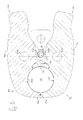
- Fig. 1b shows now in a cross section the in Fig. 1a illustrated pressing tool 2 in a position which corresponds to the second stable state of the tensioning mechanism.
- the actuating portions 6a, 6b of the pivot elements 4a, 4b abut each other in this example.
- the abutment surfaces 14a, 14b of the pressing portions 8a, 8b are spaced from each other, the receiving portion 12 is thus open, so that the components to be pressed (not shown) can be introduced.
- the bolt 28 is in this second stable state, with respect to the connecting line 40 of the rotation axes 20a, 20b, on the side of the pressing portions 8a, 8b.
- the guide of the bolt 28 is effected by circular segment-shaped, adapted to the diameter of the bolt 28 recesses 42a, 42b in the mutually facing side surfaces of the pivot elements 4a, 4b, in which from the turns of the leg spring 26, and optionally from the tabs 38a, 38b of the sliding element 36 outstanding areas of the bolt 28 are mounted. Since the bolt 28 is connected to the sliding element 36 via the tabs 38a, 38b, the sliding element 36 protrudes into the receiving area 12.
- a pulse which causes the voltage mechanism to transition from the second to the first stable state, simply by the introduction of the components to be pressed in the receiving area 12 exercise.
- a tube, a fitting or a sleeve are pressed during insertion into the receiving area 12 against the contoured, the receiving area 12 facing surface of the sliding element 36 and thereby push it backwards.
- this movement is transmitted to the pin 28 and thus also to the leg spring 26.
- the momentum caused by the introduction of the components is sufficient to release the end faces of the pressure pieces 30a, 30b from the countersinks 24a, 24b.
- the first stable state of the tension mechanism may be present when the abutment surfaces 14a, 14b of the pressing portions 8a, 8b abut each other, for example, when the receiving portion 12 is free, or when the end faces of the pressure pieces 30a, 30b have reached the end of the recesses 22a, 22b or if the inner contours 10a, 10b bear against the outer peripheral surface of a component located in the receiving region 12. It is also possible in principle for the leg spring 26 to reach its state of relaxation before one of the aforementioned positions has been reached.
- FIG Fig. 1c The position of the pivot elements 4a, 4b relative to each other in the first stable state of the tension mechanism according to the first of the aforementioned alternatives is exemplified in FIG Fig. 1c shown in cross section.
- the abutment surfaces 14a, 14b of the pressing portions 8a, 8b abut each other, whereas the operating portions 6a, 6b are spaced from each other.
- the bolt 28 is in this first stable state with respect to the connecting line 40 of the rotating shafts 20a, 20b on the side of the operating portions 6a, 6b.
- the circular segment-shaped recesses 42a, 42b are brought together on the side facing the receiving region 12 in such a way that, in cross section, a circle open on one side results, in which the hollow cylindrical pin 28 is arranged.
- the sliding element 36 is in this example just as far along the perpendicular to the connecting line 40 between the axes of rotation 20a, 20b shifted that its contoured surface is substantially in alignment with the inner contours 10a, 10b of the pressing sections 8a, 8b. In this way, an optimal all-round application of force can be achieved during cold pressing.
- the first stable state has been described so that the abutment surfaces 14a, 14b of the pressing portions 8a, 8b abut each other. This description is based on the fact that no fitting is arranged in the receiving region 12c of the pressing tool 2. If this is the case, however, the first stable state is assumed when the receiving area 12 encloses the fitting contained therein. In this state, the pressing tool 2 can be opened again without causing the fitting to be compressed. If, on the other hand, the pressing tool 2 is completely closed by the motor drive, with the abutment surfaces 14a, 14b being brought into contact with each other, the fitting is compressed.
- the first stable state does not require that the abutment surfaces 14a, 14b abut each other, but that the pressing jaws 4a, 4b are closed by the action of the leg spring 26 until a mechanical resistance has been achieved.
- This mechanical resistance is different than it is for the second stable state based on Fig. 1b has been described by the engagement of the plungers 32 in the countersinks 24.
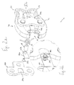
- Fig. 2a-b show another possible embodiment of the pressing tool 2 according to the invention in an exploded view.
- the difference to that in the Fig. 1a-c illustrated embodiment is that as a pulse transformer instead of a sliding element 36 two of the pivot elements 4a, 4b subsidiary plates 44a, 44b are provided.
- the plates 44a, 44b have at one end a bore 46a, 46b, through which the bolt 28 engages.
- the other end of the plates 44a, 44b protrudes in the in Fig. 2a illustrated second stable state of the tension mechanism in the receiving area 12 inside.
- the components to be pressed which are brought into the receiving area 12, press against an edge of the sheets 44a, 44b, whereby the bolt 28 and thus the leg spring 26 in the direction of the operating portions 6a, 6b are moved, the end faces the pressure pieces 30a, 30b can be released from the countersink 24a, 24b, and thus the spring spreading mechanism can again act on the actuating portions 6a, 6b.
- the assignment of in the Fig. 2a-b shown plates 44a, 44b is particularly advantageous when already manufactured pressing tools 2 to be retrofitted with a monostable tensioning mechanism. In this example, only the support plates 16a, 16b and possibly the bolt 28 would have to be exchanged and the plates 44a, 44b added.
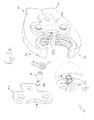
- Fig. 3a-b show a further possible embodiment of the pressing tool 2 according to the invention in an exploded view.
- the difference to those in the Fig. 1a-c and 2a-b there are no separate pulse transformers that can cause the voltage mechanism to leave the second stable state and assume the first stable state.
- the support elements 16a, 16b also have no recesses, which are provided in the previously explained embodiments primarily for guiding the tabs or sheets.
- the second stable state corresponds to the engagement of the plungers 30a, 30b in the cuts 24a, 24b.
- the transition from the second to the first stable state causing pulse can in this embodiment by a further, possibly jerky voltage of Leg spring 26 can be exercised by the operating portions 6a, 6b further merged.
- the leg spring 26 and the pin 28 are further guided in the direction of the pressing portions 6a, 6b, so that the engagement of the pressure pieces 30a, 30b in the counterbores 24a, 24b in the direction of the pressing portions 8a, 8b is released.
- Due to the then initiated spreading movement of the leg spring 26 the pressure pieces 30a, 30b are again guided in the direction of the actuating portions 6a, 6b along the side surfaces of the support elements 16a, 16b.
- the dynamics of the movement of the plungers 30a, 30b is sufficient to prevent the plungers 30a, 30b from snapping back into the recesses 24a, 24b in the backward movement. Instead, the thrust pieces 30a, 30b, driven by the leg spring 26, slide over the counterbores 24a, 24b, so that the tension mechanism can assume the first stable state.
- Fig. 4 shows a further possible embodiment of the pressing tool 2 according to the invention in a cross-sectional view.
- the second stable state of the tension mechanism does not correspond to the engagement of thrust pieces 30a, 30b in depressions 24a, 24b arranged on the carrier elements 16a, 16b, but that the second stable state corresponds to the spring dead center position.
- the perpendicular 48a, 48b drawn to the spring leg 32a, 32b at the leg end passes through the pivot axis point 20a, 20b.
- a rotational movement can not take place.
- the rotational movement of the pivot elements 4a, 4b around the axes of rotation 20a, 20b becomes possible again and the transition from the second to the first stable state of the tension mechanism becomes effective Reason of the dynamics of the relaxation movement initiated.
- the provided on the pivot elements 4a, 4b, from the turns of the leg spring 26 outstanding portions of the bolt 28 leading circular segment-shaped recesses 42a, 42b so dimensioned that the alignment of the spring legs 32a, 32b beyond the Federtot Vietnamese addition displacement of the bolt 28 and thus the leg spring 26 in the direction of the pressing sections 8a, 8b is avoided.
- Fig. 5 shows a further possible embodiment of the pressing tool 2 according to the invention in a cross-sectional view.
- the leg spring 26 has legs 32a, 32b with angled ends.
- One of the spring legs 32a is arranged in this example in a arranged on one of the pivot elements 4b groove 50, so that this pivot member 4b and the leg spring 26 are firmly connected.
- the other spring leg 32b can be slidably guided on the side surface of the other pivot member 4a.
- On this side surface a retaining cam 52 is arranged.
- the retaining cam 52 is formed so that the angled end of the spring leg 32 b can engage behind.
- This position of the spring leg 32b corresponds to the second stable state of the tension mechanism, which - as shown - is given in particular when the receiving area 12 is opened, so when the abutment surfaces 14a, 14b of the pressing portions 8a, 8b are spaced. It is basically possible to arrange a plurality of retaining cams 52 one behind the other on a pivoting element 4a, 4b. In this way, several different opening states of the receiving area 12 could be implemented.
- the engaging position of the spring leg 32b can here similar to the in the Fig. 3 and 4 shown embodiments are solved by means of an overvoltage of the leg spring 26. But it is also possible in principle, other features of the preceding embodiments, in particular the pulse transformer, with the in Fig. 5 to be shown combined embodiment.
- the present invention is not limited to specific embodiments of the pivotal elements 4a, 4b.
- the shape of the inner contour 10a, 10b of the pressing sections 8a, 8b can be selected as appropriate for the application. It is also possible to form the press sections 8a, 8b for receiving variable press attachments, which may have differently shaped inner contours 10a, 10b.
Landscapes
- Engineering & Computer Science (AREA)
- Mechanical Engineering (AREA)
- Devices For Conveying Motion By Means Of Endless Flexible Members (AREA)
- Adhesives Or Adhesive Processes (AREA)
- Press Drives And Press Lines (AREA)
- Mounting, Exchange, And Manufacturing Of Dies (AREA)
- Jigs For Machine Tools (AREA)
Abstract
Description
- Die Erfindung betrifft ein Presswerkzeug zum unlösbaren Verbinden eines Rohrs und eines Fittings mit zwei je einen Betätigungsabschnitt und einen Pressabschnitt aufweisenden Schwenkelementen, welche um je eine ihnen zugeordnete Drehachse schwenkbar sind, mit zwei den Schwenkelementen beigeordneten Trägerelementen, welche die beiden Drehachsen halten, und mit einem Spannungsmechanismus, wobei die Innenkonturen der einander gegenüberliegenden Pressabschnitte der beiden Schwenkelemente einen Aufnahmebereich bilden.
- Presswerkzeuge der eingangs genannten Art sind bereits bekannt. Als Spannungsmechanismus ist beispielsweise eine zwischen den Betätigungsabschnitten der Schwenkelemente angeordnete Feder vorgesehen, welche die Betätigungsabschnitte spreizt und somit die Pressabschnitte gleichzeitig gegeneinander drückt, so dass sich der Aufnahmebereich verengt. Als Feder wird beispielsweise eine auf Druck belastbare Schraubenfeder verwendet. Auf diese Weise können die Innenkonturen der Pressabschnitte mittels Federkraft in Anlage zur Außenumfangsflache des zu verpressenden Rohrs oder Fittings bzw. der zu verpressenden Muffe gebracht werden, bevor durch eine an den Betätigungsabschnitten der Schwenkelemente angreifende Kraftmaschine die kalte Verpressung vollzogen wird.
- Möchte ein Benutzer ein solches Presswerkzeug einsetzen, muss er einerseits die zu verpressenden Bauteile in die für die Verpressung vorgesehene Position bringen und dort halten, andererseits die Betätigungsabschnitte in einer den Spannungsmechanismus belastenden Weise gegeneinander drücken, um das Presswerkzeug für die Aufnahme der Bauteile bereit zu machen, und zusätzlich das Presswerkzeug und die damit verbundene Kraftmaschine in die zur Verpressung vorgesehene Position bringen und dort halten. Es gibt somit drei Punkte, auf welche der Benutzer zu achten hat. In der Praxis kann der Benutzer gegebenenfalls die Hilfe einer weiteren Person in Anspruch nehmen, welche eine der drei zuvor genannten Tätigkeiten übernimmt. Der Benutzer kann sich weiterhin der ersten der zuvor genannten Tätigkeiten entledigen, indem er technische Hilfsmittel heranzieht, beispielsweise indem er die zu verpressenden Bauteile fixiert, bevor das Presswerkzeug angesetzt wird. Allerdings ist dem Benutzer der Einsatz eines zuvor beschriebenen Presswerkzeugs erschwert, wenn er die Verpressung ohne fremde Hilfe oder ohne weitere technische Hilfsmittel, insbesondere ohne separate Fixierung der Bauteile durchführen möchte.
- Der vorliegenden Erfindung liegt daher das technische Problem zu Grunde, ein Presswerkzeug anzugeben, welches einfacher zu handhaben ist.
- Gemäß der Lehre der vorliegenden Erfindung wird das technische Problem dadurch gelöst, dass der Spannungsmechanismus bistabil ausgebildet ist, und dass der durch die Innenkonturen gebildete Aufnahmebereich im ersten stabilen Zustand enger als im zweiten stabilen Zustand ist.
- Erfindungsgemäß wurde erkannt, dass die Handhabbarkeit eines Presswerkzeugs der eingangs genannten Art vereinfacht werden kann, wenn ein bistabiler Spannungsmechanismus vorgesehen ist. Dies bedeutet, dass der Spannungsmechanismus zwei Zustände einnehmen kann, die er zumindest ohne Einwirkung eines Impulses nicht wieder verlässt. Im ersten stabilen Zustand des Spannungsmechanismus ist der Aufnahmebereich enger als im zweiten stabilen Zustand. Dies ist insbesondere dann der Fall, wenn der Spannungsmechanismus die größtmögliche Spreizung der Betätigungsabschnitte vollzogen hat, so dass die Stoßflächen der Pressabschnitte aneinander anliegen. Es ist natürlich auch möglich, den ersten stabilen Zustand einzunehmen, wenn die Innenkonturen der Pressabschnitte an einem sich in dem Aufnahmebereich befindlichen Bauteil anliegen, ohne dass die Stoßflächen der Pressabschnitte in Kontakt kommen. Im zweiten stabilen Zustand sind die Schwenkelemente zueinander so ausgerichtet, dass der Aufnahmebereich weiter als im ersten stabilen Zustand und somit insbesondere bereit zur Aufnahme eines zu verpressenden Bauteils, beispielsweise Rohr, Fitting oder Muffe, ist.
- Die Handhabung eines Presswerkzeugs der eingangs genannten Art wird einem Benutzer vereinfacht, indem er zunächst den Spannungsmechanismus in den zweiten stabilen Zustand bringt, in welchem das Presswerkzeug auf Grund der durch den Spannungsmechanismus bewirkten Vorspannung verharrt. Mit dem so voreingestellten Presswerkzeug kann sich der Benutzer allein auf die Positionierung der zu verpressenden Bauteile und auf die Positionierung des Presswerkzeugs an den zu verpressenden Bauteilen konzentrieren. Die Hilfe einer weiteren Person oder zusätzliche, meist improvisierte technische Hilfsmittel, sind nicht mehr erforderlich. Der Benutzer kann also das Bauteil in den Aufnahmebereich einführen, die korrekte Position der Pressabschnitte bezüglich des Bauteils prüfen und anschließend einen Impuls bewirken, welcher den Spannungsmechanismus veranlasst, den zweiten stabilen Zustand zu verlassen und den ersten stabilen Zustand einzunehmen, in welchem der Aufnahmebereich enger ist, insbesondere in welchem die Innenkonturen an der Außenumfangsflache des Bauteils anliegen. Vorzugsweise kann der den Übergang vom zweiten in den ersten stabilen Zustand bewirkende Impuls an den Innenkonturen der Pressabschnitte, gegebenenfalls durch die zu verpressenden Bauteile selbst bewirkt werden. Wenn die Innenkonturen der Pressabschnitte die Bauteile zuverlässig umschließen, kann der Benutzer die Kraftmaschine aktivieren und die Verpressung vollziehen lassen.
- Vorzugsweise ist die in dem ersten stabilen Zustand von dem Spannungsmechanismus über die Innenkonturen der Pressabschnitte auf die Außenumfangsfläche des Bauteils übertragene Kraft nicht groß genug, um bereits eine Umformung der Bauteile vorzunehmen. Mit anderen Worten ist vorzugsweise der dem Spannungsmechanismus von dem Bauteil entgegengesetzte Widerstand im ersten stabilen Zustand groß genug, um eine Umformung zu verhindern. Die eigentliche Verpressung wird dann erst durch Betätigung der Kraftmaschine bewirkt. Auf diese Weise kann ein Benutzer des Presswerkzeugs die Positionen der Bauteile und des Presswerkzeugs im ersten stabilen Zustand prüfen und, falls notwendig, korrigieren, indem er den Spannungsmechanismus des Presswerkzeugs wieder in den zweiten stabilen Zustand bringt, den Aufnahmebereich also weitet, und die Pressabschnitte neu an den Bauteilen ansetzt. Auf diese Weise wird es einem Benutzer erleichtert, eine korrekte Verpressung durchzuführen, denn er kann seine Aufmerksamkeit fast ausschließlich der Positionierung widmen.
- In einer bevorzugten Ausgestaltung des Presswerkzeugs weist der Spannungsmechanismus eine zwischen den Schwenkelementen angeordnete Schenkelfeder auf. Je ein Federschenkel kann dann an den einander zugewandten Außenflächen der Schwenkelemente anliegen und somit einen optimalen Kraftübertrag von den Schwenkelementen auf die Federschenkel und umgekehrt gewährleisten. Darüber hinaus sind, meist aus metallischen Werkstoffen gefertigte Schenkelfedern wenig anfällig gegen Verschleiß und auf dem Markt mit verschiedenen Eigenschaften, beispielsweise Federkonstanten bzw. geometrischen Formen, verfügbar, so dass das Presswerkzeug durch gezielte Wahl einer bestimmten Schenkelfeder zur Erfüllung unterschiedlicher Anforderungen ausgestaltet werden kann.
- Ferner ist es bevorzugt, dass die Schenkelfeder gegenüber den Drehachsen der Schwenkelemente beweglich gelagert ist. Auf diese Weise kann die Vorspannung des Spannungsmechanismus sehr flexibel eingestellt werden. Vorzugsweise ist die Schenkelfeder entlang der Senkrechten zu einer Verbindungslinie zwischen den beiden Drehachsen der Schwenkelemente beweglich. Weiter ist es bevorzugt, dass eine bestimmte Position entlang der zuvor genannten Senkrechten einer bestimmten Ausrichtung der Federschenkel zueinander entspricht. Auf diese Weise kann der Arretiermechanismus, welcher einen zweiten stabilen Zustand des Spannungsmechanismus ermöglicht, sehr flexibel in das Presswerkzeug eingearbeitet werden. Darüber hinaus kann das Presswerkzeug auf diese Weise sehr flexibel auf verschiedene, den Übergang des Spannungsmechanismus vom zweiten in den ersten stabilen Zustand auslösende Impulse empfindlich ausgestaltet werden.
- In einer weiteren vorteilhaften Ausgestaltung des Presswerkzeugs weist der Spannungsmechanismus zusätzlich einen die Windungen der Schenkelfeder durchgreifenden, hohlen Bolzen und zwei zumindest teilweise in dem Bolzen federnd gelagerte Druckstücke auf. Mit dieser Anordnung lässt sich die Beziehung zwischen der Position der Schenkelfeder entlang der Senkrechten zur Verbindungslinie zwischen den Drehachsen und der Ausrichtung der Federschenkel zueinander besonders zuverlässig gewährleisten. Der Bolzen stellt auch sicher, dass die Schwenkbewegungen der Schwenkelemente symmetrisch ausführbar sind. Darüber hinaus bietet der Bolzen zusätzliche Alternativen, den Übergang des Spannungsmechanismus vom zweiten in den ersten stabilen Zustand bewirkende Impulse auf den Spannungsmechanismus zu übertragen. Die in dem Bolzen federnd gelagerten Druckstücke ermöglichen es, den Arretiermechanismus des zweiten stabilen Zustands des Spannungsmechanismus auf die den Schwenkelementen zugewandten Seitenflächen der Trägerelemente zu übertragen.
- Beispielsweise kann das Trägerelement eine an ein Druckstück angepasste Senkung aufweisen. Wird eine Stirnfläche des Druckstücks durch eine Bewegung des Bolzens gleitend, und unter Belastung der federnden Lagerung des Druckstücks in dem Bolzen, entlang der den Schwenkelementen zugewandten Seitenflächen des Trägerelements geführt, kann das Druckstück am Ort der Senkung in diese einrasten. Vorzugsweise entspricht die Position des Bolzens, die korrespondierende Position der Feder und die korrespondierende Ausrichtung der Federschenkel zueinander, in welcher das Druckstück in die Senkung eingreift, gerade der zweiten stabilen Position des Spannungsmechanismus. Die von dem Spannungsmechanismus auf die Schwenkelemente übertragene Kraft reicht dabei nicht aus, um den Eingriff des Druckstücks in die Senkung aufzulösen. Vielmehr ist dazu ein Impuls nötig.
- In einer weiteren vorteilhaften Ausgestaltung des Presswerkzeugs ist mindestens ein an den Innenkonturen der Pressabschnitte angeordneter Impulsübertrager vorgesehen. Auf diese Weise kann der Impuls durch die in den Aufnahmebereich eingeführten, zur Verpressung vorgesehenen Bauteile bewirkt werden. Beispielsweise können den Schwenkelementen beigeordnete Bleche vorgesehen sein. Die in den Aufnahmebereich eingeführten Bauteile können dann gegen die dem Aufnahmebereich zugewandte Kante der Bleche drücken und so den Impuls auf den Spannungsmechanismus übertragen. Auf diese Weise können insbesondere einen monostabilen Spannungsmechanismus aufweisende Presswerkzeuge nachgerüstet und somit mit einem bistabilen Spannungsmechanismus ausgestattet werden. Es ist aber alternativ auch möglich, ein zwischen den Innenkonturen der Pressabschnitte angeordnetes, insbesondere integriertes Schiebeelement vorzusehen. Das Schiebeelement weist vorzugsweise eine an die Innenkonturen der Pressabschnitte der Schwenkelemente angepasste Seitenfläche auf. Auf diese Weise kann vermieden werden, dass zwischen den beiden Innenkonturen während des Verpressungsvorgangs eine Lücke besteht, welche ein unsymmetrisches, gegebenenfalls nicht hinreichend dichtendes Pressergebnis zur Folge haben könnte.
- Weiterhin kann die Senkung in einer am Trägerelement angeordneten Aussparung angeordnet sein. Die Aussparung ist insbesondere dazu geeignet, den Impulsübertragern einen Führungsbereich zu bieten. Dadurch kann die Stabilität des Spannungsmechanismus weiter verbessert werden.
- In einer weiteren vorteilhaften Ausgestaltung des Presswerkzeugs weist der Spannungsmechanismus eine Schenkelfeder mit abgewinkelte Enden aufweisenden Schenkeln und mindestens eine an wenigstens einem der Schwenkelemente angeordnete Haltenocke auf. Auf diese Weise kann der Arretiermechanismus als bauliche Ausgestaltung an der Schenkelfeder und an den Schwenkelementen vorgesehen werden. Die Anzahl der den Spannungsmechanismus bildenden Bauelemente lässt sich so gering halten. Dadurch kann die Zuverlässigkeit des Presswerkzeugs auch nach vielen Presszyklen gewährleistet werden.
- Im Folgenden wird die Erfindung an Hand von in einer Zeichnung dargestellten Ausführungsbeispielen näher erläutert. In der Zeichnung zeigen:
- Fig. 1a-c
- ein Ausführungsbeispiel des erfindungsgemäßen Presswerkzeugs mit einem Schiebeelement als Impulsübertrager in einer Explosionsansicht und zwei Querschnittsansichten,
- Fig. 2a-b
- ein weiteres Ausführungsbeispiel des erfindungsgemäßen Presswerkzeugs mit Blechen als Impulsübertrager in einer Explosionsansicht,
- Fig. 3a-b
- ein weiteres Ausführungsbeispiel des erfindungsgemäßen Presswerkzeugs ohne separaten Impulsübertrager in einer Explosionsansicht,
- Fig. 4
- ein weiteres Ausführungsbeispiel des erfindungsgemäßen Presswerkzeugs mit einem der Federtotpunktlage entsprechenden zweiten stabilen Zustand des Spannungsmechanismus in einer Querschnittsansicht und
- Fig. 5
- ein weiteres Ausführungsbeispiel des erfindungsgemäßen Presswerkzeugs mit einer Schenkelfeder, deren Schenkel abgewinkelte Enden aufweisen, in einer Querschnittsansicht.
-
Fig. 1a zeigt ein Ausführungsbeispiel des erfindungsgemäßen Presswerkzeugs 2 in einer Explosionsdarstellung. Zwei in diesem Beispiel symmetrische Schwenkelemente 4a, 4b sind einander gegenüberliegend angeordnet. Grundsätzlich können die Schwenkelemente 4a, 4b auch eine unterschiedliche bauliche Ausgestaltung aufweisen. Die Schwenkelemente 4a, 4b weisen je einen Betätigungsabschnitt 6a, 6b und je einen Pressabschnitt 8a, 8b auf. Je eine Fläche der Pressabschnitte 8a, 8b weist eine Innenkontur 10a, 10b auf, so dass zwischen den Innenkonturen 10a, 10b der einander gegenüberliegenden Pressabschnitte 8a, 8b ein Aufnahmebereich 12 gebildet wird. In der Darstellung derFig. 1a ist der Aufnahmebereich 12 offen gezeigt. Mit anderen Worten, die Stoßflächen 14a, 14b der Pressabschnitte 8a, 8b sind voneinander beabstandet. - An den äußeren Seitenflächen der Schwenkelemente 4a, 4b sind zwei Trägerelemente 16a, 16b angeordnet, welche in diesem Beispiel in T-Form ausgebildet sind. Durch entsprechend an den Trägerelementen 16a, 16b und an den Schwenkelementen 4a, 4b vorgesehene Bohrungen 18a, 18b sind die Schwenkelemente 4a, 4b an den Trägerelementen 16a, 16b, beispielsweise mittels eines Bolzens schwenkbar angelenkt. Auf diese Weise ist jedem Schwenkelement 4a, 4b eine Drehachse 20a, 20b zugeordnet. Eine weitere Bohrung 18c an jedem Trägerelement 16a, 16b ist für die Verbindung des Trägerelements 16a, 16b und damit des Presswerkzeugs 2 mit einer Kraftmaschine (nicht dargestellt) vorgesehen. Die den Schwenkelementen 4a, 4b zugewandten Seitenflächen der Trägerelemente 16a, 16b weisen in diesem Beispiel je eine Aussparung 22a, 22b und eine in der Aussparung 22a, 22b angeordnete Senkung 24a, 24b auf. Die Senkung 24a, 24b kann beispielsweise in der Form einer Hohlkalotte ausgebildet sein.
- Der Spannungsmechanismus weist in dem in
Fig. 1a gezeigten Ausführungsbeispiel eine Schenkelfeder 26 auf. Zusätzlich ist ein hohler Bolzen 28, welcher in diesem Beispiel in der Form eines Hohlzylinders ausgebildet ist und die Windungen der Schenkelfeder 26 durchgreift, vorgesehen. An jeder Stirnseite des Bolzens 28 ist je ein Druckstück 30a, 30b federnd gelagert. Eine Stirnseite des Druckstücks 30a, 30b wird gegen die den Schwenkelementen 4a, 4b zugewandte Seitenfläche des Trägerelements 16a, 16b im Bereich der Aussparung 22a, 22b gedrückt und kann, beispielsweise über eine Bewegung des Bolzens 28 gleitend geführt werden. In die Senkung 24a, 24b kann das Druckstück 30a, 30b einrasten, so dass eine weitere Bewegung des Bolzens 28 gehemmt wird. Die Form der Senkung 24a, 24b ist dabei vorzugsweise an die Form des Druckstücks 30a, 30b angepasst. Eine Veränderung der Ausrichtung der Federschenkel 32a, 32b zueinander ist mit einer Federbewegung quer zur Federwindungsachse 34, insbesondere entlang der Senkrechten zur Verbindungslinie 40 (sieheFig. 1b und1c ) zwischen den beiden Drehachsen 20a, 20b verknüpft. Eine solche Federbewegung führt den Bolzen 28 und die Druckstücke 30a, 30b mit, so dass die Druckstücke 30a, 30b entlang der Fläche der Aussparung 22a, 22b geführt werden. Greift die Stirnseite des Druckstücks 30a, 30b in die Senkung 24a, 24b ein, reicht jedoch die Federkraft nicht aus, das Druckstück 30a, 30b aus der Senkung 24a, 24b zu bewegen. Der Eingriff der Stirnseite des Druckstücks 30a, 30b in die Senkung 24a, 24b entspricht in diesem Beispiel also dem zweiten stabilen Zustand des Spannungsmechanismus. - Um den in
Fig. 1a gezeigten Spannungsmechanismus zum Verlassen des zweiten stabilen Zustands zu veranlassen, ist ein Schiebeelement 36 als Impulsübertrager vorgesehen. Eine Fläche des Schiebeelements 36 ist an die Innenkonturen 10a, 10b der Pressabschnitte 8a, 8b angepasst. Die Innenkonturen 10a, 10b der Pressabschnitte 8a, 8b weisen entsprechende Ausnehmungen auf, so dass das Schiebeelement 36 bündig in die Pressabschnitte 8a, 8b integrierbar ist. Auf der den Innenkonturen 10a, 10b der Pressabschnitte 8a, 8b abgewandten Seite weist das Schiebeelement 36 zwei Laschen 38a, 38b auf. Der Abstand zwischen den Laschen 38a, 38b ist so bemessen, dass die Schenkelfeder 26 dazwischen angeordnet werden kann. Dementsprechend durchgreift der Bolzen 28 nicht nur die Windungen der Schenkelfeder 26 sondern auch die Laschen 38a, 38b des Schiebeelements 36. Auf diese Weise sind das Schiebeelement 36, die Schenkelfeder 26, der Bolzen 28 und die Druckstücke 30a, 30b vereint beweglich miteinander verbunden. Die Aussparungen 22a, 22b an den Trägerelementen 16a, 16b sind so bemessen, dass die Laschen 38a, 38b flächig in ihnen geführt werden können. Dadurch kann insbesondere die Stabilität der Anordnung des Schiebeelements 36 in der Richtung parallel zur Verbindungslinie 40 zwischen den Drehachsen 20a, 20b verbessert werden. -
Fig. 1b zeigt nun in einem Querschnitt das inFig. 1a dargestellte Presswerkzeug 2 in einer Position, welche dem zweiten stabilen Zustand des Spannungsmechanismus entspricht. Die Betätigungsabschnitte 6a, 6b der Schwenkelemente 4a, 4b liegen in diesem Beispiel aneinander an. Die Stoßflächen 14a, 14b der Pressabschnitte 8a, 8b sind beabstandet voneinander, der Aufnahmebereich 12 ist demnach offen, so dass die zu verpressenden Bauteile (nicht gezeigt) eingeführt werden können. - Der Bolzen 28 befindet sich in diesem zweiten stabilen Zustand, bezüglich der Verbindungslinie 40 der Drehachsen 20a, 20b, auf der Seite der Pressabschnitte 8a, 8b. Die Führung des Bolzens 28 wird durch kreissegmentförmige, an den Durchmesser des Bolzens 28 angepasste Ausnehmungen 42a, 42b in den einander zugewandten Seitenflächen der Schwenkelemente 4a, 4b bewirkt, in welchen die aus den Windungen der Schenkelfeder 26, und gegebenenfalls aus den Laschen 38a, 38b des Schiebeelements 36 hervorragenden Bereiche des Bolzens 28 gelagert sind. Da der Bolzen 28 über die Laschen 38a, 38b mit dem Schiebeelement 36 verbunden ist, ragt das Schiebeelement 36 in den Aufnahmebereich 12 hinein.
- Auf diese Weise lässt sich ein Impuls, welcher den Spannungsmechanismus zum Übergang vom zweiten in den ersten stabilen Zustand veranlasst, einfach durch das Einführen der zu verpressenden Bauteile in den Aufnahmebereich 12 ausüben. Ein Rohr, ein Fitting oder eine Muffe werden beim Einführen in den Aufnahmebereich 12 gegen die konturierte, dem Aufnahmebereich 12 zugewandte Fläche des Schiebeelements 36 gedrückt und schieben es dadurch nach hinten. Über die rückwärtige Seite des Schiebeelements 36 wird diese Bewegung auf den Bolzen 28 und damit auch auf die Schenkelfeder 26 übertragen. Insbesondere reicht der durch das Einführen der Bauteile bewirkte Impuls aus, die Stirnseiten der Druckstücke 30a, 30b aus den Senkungen 24a, 24b zu lösen. Die die Druckstücke 30a, 30b an die Trägerelemente 16a, 16b drückende Kraft reicht dann jedoch nicht mehr aus, die Kraft der Schenkelfeder 26 weiter zu kompensieren, so dass durch die Wirkung der Kraft der Schenkelfeder 26 die Stirnseiten der Druckstücke 30a, 30b gleitend entlang der Aussparung 22a, 22b geführt werden, bis der erste stabile Zustand des Spannungsmechanismus erreicht ist.
- Der erste stabile Zustand des Spannungsmechanismus kann dann vorliegen, wenn die Stoßflächen 14a, 14b der Pressabschnitte 8a, 8b aneinander anliegen, beispielsweise wenn der Aufnahmebereich 12 frei ist, oder wenn die Stirnseiten der Druckstücke 30a, 30b das Ende der Aussparungen 22a, 22b erreicht haben oder wenn die Innenkonturen 10a, 10b an der Außenumfangsfläche eines im Aufnahmebereich 12 befindlichen Bauteils anliegen. Es ist grundsätzlich auch möglich, dass die Schenkelfeder 26 ihren Entspannungszustand erreicht, bevor eine der zuvor genannten Positionen erreicht wurde.
- Die Position der Schwenkelemente 4a, 4b zueinander im ersten stabilen Zustand des Spannungsmechanismus gemäß der ersten der zuvor genannten Alternativen ist beispielhaft in
Fig. 1c im Querschnitt gezeigt. Die Stoßflächen 14a, 14b der Pressabschnitte 8a, 8b liegen aneinander an, wohingegen die Betätigungsabschnitte 6a, 6b voneinander beabstandet sind. Der Bolzen 28 befindet sich in diesem ersten stabilen Zustand, bezüglich der Verbindungslinie 40 der Drehachsen 20a, 20b, auf der Seite der Betätigungsabschnitte 6a, 6b. Die kreissegmentförmigen Ausnehmungen 42a, 42b sind an der dem Aufnahmebereich 12 zugewandten Seite so zusammengeführt, dass sich im Querschnitt ein an einer Seite offener Kreis ergibt, in welchem der hohlzylinderförmige Bolzen 28 angeordnet ist. Das Schiebeelement 36 ist in diesem Beispiel gerade so weit entlang der Senkrechten zur Verbindungslinie 40 zwischen den Drehachsen 20a, 20b verschoben, dass dessen konturierte Fläche im Wesentlichen fluchtend zu den Innenkonturen 10a, 10b der Pressabschnitte 8a, 8b liegt. Auf diese Weise kann eine optimale allseitige Kraftausübung beim kalten Verpressen erreicht werden. - Zuvor ist der erste stabile Zustand so beschrieben worden, dass die Stoßflächen 14a, 14b der Pressabschnitte 8a, 8b aneinander anliegen. Diese Beschreibung beruht darauf, dass im Aufnahmebereich 12c des Presswerkzeuges 2 kein Fitting angeordnet ist. Ist das dagegen der Fall, so wird der erste stabile Zustand dann angenommen, wenn der Aufnahmebereich 12 den darin enthaltenen Fitting umschließt. In diesem Zustand kann das Presswerkzeug 2 erneut geöffnet werden, ohne dass es zu einem Verpressen des Fittings gekommen ist. Wird dagegen das Presswerkzeug 2 durch den motorischen Antrieb vollständig geschlossen, wobei die Stoßflächen 14a, 14b zur Anlage aneinander gebracht werden, so wird der Fitting verpresst. Der erste stabile Zustand erfordert daher nicht, dass die Stoßflächen 14a, 14b aneinander anliegen, sondern dass die Pressbacken 4a, 4b unter Kraftwirkung der Schenkelfeder 26 soweit geschlossen werden, bis ein mechanischer Widerstand erreicht worden ist. Dieser mechanische Widerstand ist dabei ein anderer, als er für den zweiten stabilen Zustand anhand von
Fig. 1b durch den Eingriff der Druckstücke 32 in die Senkungen 24 beschrieben worden ist. -
Fig. 2a-b zeigen ein weiteres möglich Ausführungsbeispiel des erfindungsgemäßen Presswerkzeugs 2 in einer Explosionsdarstellung. Der Unterschied zu dem in denFig. 1a-c dargestellten Ausführungsbeispiel besteht darin, dass als Impulsübertrager statt eines Schiebeelements 36 zwei den Schwenkelementen 4a, 4b beigeordnete Bleche 44a, 44b vorgesehen sind. Das Prinzip würde jedoch ähnlich funktionieren, wenn statt zwei Blechen 44a, 44b nur ein Blech an einer Seite der Schwenkelemente 4a, 4b vorgesehen ist. Die Bleche 44a, 44b weisen an einem Ende eine Bohrung 46a, 46b auf, durch welche der Bolzen 28 greift. Das andere Ende der Bleche 44a, 44b ragt in dem inFig. 2a dargestellten zweiten stabilen Zustand des Spannungsmechanismus in den Aufnahmebereich 12 hinein. Auch hier können also die zu verpressenden Bauteile, welche in den Aufnahmebereich 12 gebracht werden, gegen eine Kante der Bleche 44a, 44b drücken, wodurch der Bolzen 28 und damit auch die Schenkelfeder 26 in Richtung der Betätigungsabschnitte 6a, 6b bewegt werden, wobei die Stirnseiten der Druckstücke 30a, 30b sich aus der Senkung 24a, 24b lösen und somit der Federspreizmechanismus an den Betätigungsabschnitten 6a, 6b wieder wirken kann. Die Beiordnung der in denFig. 2a-b dargestellten Bleche 44a, 44b ist insbesondere vorteilhaft, wenn bereits gefertigte Presswerkzeuge 2 mit monostabilem Spannungsmechanismus nachgerüstet werden sollen. In diesem Beispiel wären lediglich die Trägerplatten 16a, 16b und gegebenenfalls der Bolzen 28 auszutauschen sowie die Bleche 44a, 44b hinzuzufügen. -
Fig. 3a-b zeigen ein weiteres mögliches Ausführungsbeispiel des erfindungsgemäßen Presswerkzeugs 2 in einer Explosionsansicht. Der Unterschied zu den in denFig. 1a-c und 2a-b dargestellten Beispielen ist, dass keine separaten Impulsübertrager vorgesehen sind, welche den Spannungsmechanismus veranlassen können, den zweiten stabilen Zustand zu verlassen und den ersten stabilen Zustand einzunehmen. Dementsprechend weisen die Trägerelemente 16a, 16b auch keine Aussparungen auf, welche bei den zuvor erläuterten Ausführungsbeispielen vornehmlich zur Führung der Laschen bzw. Bleche vorgesehen sind. Auch hier entspricht der zweite stabile Zustand dem Eingriff der Druckstücke 30a, 30b in die Senkungen 24a, 24b. - Der den Übergang vom zweiten in den ersten stabilen Zustand bewirkende Impuls kann bei diesem Ausführungsbeispiel durch eine weitere, gegebenenfalls ruckartige Spannung der Schenkelfeder 26 ausgeübt werden, indem die Betätigungsabschnitte 6a, 6b noch weiter zusammengeführt werden. Durch diese Bewegung werden die Schenkelfeder 26 und der Bolzen 28 weiter in Richtung der Pressabschnitte 6a, 6b geführt, so dass der Eingriff der Druckstücke 30a, 30b in die Senkungen 24a, 24b in Richtung der Pressabschnitte 8a, 8b gelöst wird. Durch die dann ausgelöste Spreizbewegung der Schenkelfeder 26 werden die Druckstücke 30a, 30b wieder in Richtung der Betätigungsabschnitte 6a, 6b entlang der Seitenflächen der Trägerelemente 16a, 16b geführt. Allerdings reicht die Dynamik der Bewegung der Druckstücke 30a, 30b aus, um zu verhindern, dass die Druckstücke 30a, 30b in der Rückwärtsbewegung wieder in den Senkungen 24a, 24b einrasten. Stattdessen gleiten die Druckstücke 30a, 30b, von der Schenkelfeder 26 getrieben, über die Senkungen 24a, 24b hinweg, so dass der Spannungsmechanismus den ersten stabilen Zustand einnehmen kann.
-
Fig. 4 zeigt ein weiteres mögliches Ausführungsbeispiel des erfindungsgemäßen Presswerkzeugs 2 in einer Querschnittsansicht. Der Unterschied zu den vorhergehenden Ausführungsbeispielen besteht darin, dass der zweite stabile Zustand des Spannungsmechanismus nicht dem Einrasten von Druckstücken 30a, 30b in an den Trägerelementen 16a, 16b angeordneten Senkungen 24a, 24b entspricht, sondern dass der zweite stabile Zustand gerade der Federtotpunktlage entspricht. In diesem Fall zeigt die von den Federschenkeln 32a, 32b auf die Schwenkelemente 4a, 4b ausgeübte Kraft in Richtung der entsprechenden Drehachsen 20a, 20b. Mit anderen Worten, die zum Federschenkel 32a, 32b am Schenkelende gezeichnete Senkrechte 48a, 48b verläuft durch den Drehachsenpunkt 20a, 20b. In diesem Beispiel wird der Widerstand zu einer weiteren Bewegung der Federschenkel 32a, 32b von den Trägerelementen 16a, 16b gebildet, welche die Drehachsen 20a, 20b halten. Eine Drehbewegung kann nicht stattfinden. - Wird nun durch eine weitere Überdehnung der Schenkelfeder 26 die Kraftrichtung in Richtung der Betätigungsabschnitte 6a, 6b verschoben, wird die Drehbewegung der Schwenkelemente 4a, 4b um die Drehachsen 20a, 20b wieder möglich und der Übergang vom zweiten in den ersten stabilen Zustand des Spannungsmechanismus wird auf Grund der Dynamik der Entspannungsbewegung eingeleitet. Vorzugsweise sind die an den Schwenkelementen 4a, 4b vorgesehenen, die aus den Windungen der Schenkelfeder 26 hervorragenden Bereiche des Bolzens 28 führenden, kreissegmentförmigen Ausnehmungen 42a, 42b so bemessen, dass eine die Ausrichtung der Federschenkel 32a, 32b über die Federtotpunktlage hinaus ermöglichende Verschiebung des Bolzens 28 und damit der Schenkelfeder 26 in Richtung der Pressabschnitte 8a, 8b vermieden wird.
-
Fig. 5 zeigt ein weiteres mögliches Ausführungsbeispiel des erfindungsgemäßen Presswerkzeugs 2 in einer Querschnittsansicht. Der Unterschied zu den vorhergehenden Ausführungsbeispielen besteht darin, dass die Schenkelfeder 26 Schenkel 32a, 32b mit abgewinkelten Enden aufweist. Einer der Federschenkel 32a ist in diesem Beispiel in einer an einem der Schwenkelemente 4b angeordneten Nut 50 angeordnet, so dass dieses Schwenkelement 4b und die Schenkelfeder 26 fest verbunden sind. Der andere Federschenkel 32b hingegen kann an der Seitenfläche des anderen Schwenkelements 4a gleitend geführt werden. An dieser Seitenfläche ist eine Haltenocke 52 angeordnet. Die Haltenocke 52 ist so ausgebildet, dass das abgewinkelte Ende des Federschenkels 32b sie hintergreifen kann. Diese Stellung des Federschenkels 32b entspricht dem zweiten stabilen Zustand des Spannungsmechanismus, welcher - wie dargestellt - insbesondere dann gegeben ist, wenn der Aufnahmebereich 12 geöffnet ist, also wenn die Stoßflächen 14a, 14b der Pressabschnitte 8a, 8b beabstandet sind. Es ist grundsätzlich möglich, an einem Schwenkelement 4a, 4b mehrere Haltenocken 52 hintereinander anzuordnen. Auf diese Weise könnten mehrere unterschiedliche Öffnungszustände des Aufnahmebereichs 12 umgesetzt werden. Durch das Hintergreifen ist der Federschenkel 32b daran gehindert, entlang der Seitenfläche des Schwenkelements 4a zu gleiten und damit die durch den Kraftübertrag von dem Federschenkel 32b auf das Schwenkelement 4a bewirkte Ausgleichs- bzw. Entspannungsbewegung der Schenkelfeder 26 zu ermöglichen. Die hintergreifende Lage des Federschenkels 32b kann hier ähnlich wie in den in denFig. 3 und4 gezeigten Ausführungsbeispielen mittels einer Überspannung der Schenkelfeder 26 gelöst werden. Es ist aber grundsätzlich auch möglich, andere Merkmale der vorhergehenden Ausführungsbeispiele, insbesondere die Impulsübertrager, mit dem inFig. 5 gezeigten Ausführungsbeispiel zu kombinieren. - Die vorliegende Erfindung ist nicht auf bestimmte Ausgestaltungen der Schwenkelemente 4a, 4b beschränkt. So kann beispielsweise die Form der Innenkontur 10a, 10b der Pressabschnitte 8a, 8b so gewählt werden, wie es für die Anwendung zweckmäßig ist. Es ist auch möglich, die Pressabschnitte 8a, 8b zur Aufnahme von variablen Pressaufsätzen auszubilden, welche unterschiedlich geformte Innenkonturen 10a, 10b aufweisen können.
- Darüber hinaus betreffen die in den
Fig. 1 bis 5 gezeigten Ausführungsbeispiele der vorliegenden Erfindung Presswerkzeuge 2, welche für eine Betätigung mittels einer Kraftmaschine vorgesehen sind. Es ist jedoch auch möglich, die Merkmale der vorliegenden Erfindung auf manuell betätigbare Presswerkzeuge 2 zu übertragen, ohne den Rahmen der vorliegenden Erfindung zu verlassen.
Claims (10)
- Presswerkzeug (2) zum unlösbaren Verbinden eines Rohrs und eines Fittings- mit zwei je einen Betätigungsabschnitt (6a, 6b) und einen Pressabschnitt (8a, 8b) aufweisenden Schwenkelementen (4a, 4b), welche um je eine ihnen zugeordnete Drehachse (20a, 20b) schwenkbar sind,- mit zwei den Schwenkelementen (4a, 4b) beigeordneten Trägerelementen (16a, 16b), welche die beiden Drehachsen (20a, 20b) halten, und- mit einem Spannungsmechanismus,- wobei die Innenkonturen (10a, 10b) der einander gegenüberliegenden Pressabschnitte (8a, 8b) der beiden Schwenkelemente (4a, 4b) einen Aufnahmebereich (12) bilden,dadurch gekennzeichnet,- dass der Spannungsmechanismus bistabil ausgebildet ist, und- dass der durch die Innenkonturen (10a, 10b) gebildete Aufnahmebereich (12) im ersten stabilen Zustand enger als im zweiten stabilen Zustand ist.
- Presswerkzeug nach Anspruch 1,
dadurch gekennzeichnet,
dass der Spannungsmechanismus eine zwischen den Schwenkelementen (4a, 4b) angeordnete Schenkelfeder (26) aufweist. - Presswerkzeug nach Anspruch 1 oder 2,
dadurch gekennzeichnet,
dass die Schenkelfeder (26) gegenüber den Drehachsen (20a, 20b) der Schwenkelemente (4a, 4b) beweglich gelagert ist. - Presswerkzeug nach Anspruch 2 oder 3,
dadurch gekennzeichnet,
dass der Spannungsmechanismus zusätzlich einen die Windungen der Schenkelfeder (26) durchgreifenden, hohlen Bolzen (28) und zwei zumindest teilweise in dem Bolzen (28) federnd gelagerte Druckstücke (30a, 30b) aufweist. - Presswerkzeug nach Anspruch 4,
dadurch gekennzeichnet,
dass das Trägerelement (16a, 16b) eine an ein Druckstück (30a, 30b) angepasste Senkung (24a, 24b) aufweist. - Presswerkzeug nach Anspruch 1 bis 5,
dadurch gekennzeichnet,
dass mindestens ein an den Innenkonturen (10a, 10b) der Pressabschnitte (8a, 8b) angeordneter Impulsübertrager vorgesehen ist. - Presswerkzeug nach Anspruch 6,
dadurch gekennzeichnet,
dass als Impulsübertrager den Schwenkelementen (4a, 4b) beigeordnete Bleche (44a, 44b) vorgesehen sind. - Presswerkzeug nach Anspruch 6,
dadurch gekennzeichnet,
dass als Impulsübertrager ein zwischen den Innenkonturen (10a, 10b) der Pressabschnitte (8a, 8b) angeordnetes Schiebeelement (36) vorgesehen ist. - Presswerkzeug nach einem der Ansprüche 5 bis 8,
dadurch gekennzeichnet,
dass die Senkung (24a, 24b) in einer am Trägerelement (16a, 16b) angeordneten Aussparung (22a, 22b) angeordnet ist. - Presswerkzeug nach einem der Ansprüche 1 bis 9,
dadurch gekennzeichnet,
dass der Spannungsmechanismus eine Schenkelfeder (26) mit abgewinkelte Enden aufweisenden Schenkeln (32a, 32b) und mindestens eine an wenigstens einem der Schwenkelemente (4a, 4b) angeordnete Haltenocke (52) aufweist.
Applications Claiming Priority (1)
| Application Number | Priority Date | Filing Date | Title |
|---|---|---|---|
| DE102007061164A DE102007061164B4 (de) | 2007-12-17 | 2007-12-17 | Presswerkzeug mit bistabilem Spannungsmechanismus |
Publications (2)
| Publication Number | Publication Date |
|---|---|
| EP2072188A1 true EP2072188A1 (de) | 2009-06-24 |
| EP2072188B1 EP2072188B1 (de) | 2012-01-04 |
Family
ID=40365335
Family Applications (1)
| Application Number | Title | Priority Date | Filing Date |
|---|---|---|---|
| EP08105767A Not-in-force EP2072188B1 (de) | 2007-12-17 | 2008-11-11 | Presswerkzeug mit bistabilem Spannungsmechanismus |
Country Status (5)
| Country | Link |
|---|---|
| EP (1) | EP2072188B1 (de) |
| AT (1) | ATE539849T1 (de) |
| DE (1) | DE102007061164B4 (de) |
| DK (1) | DK2072188T3 (de) |
| ES (1) | ES2380599T3 (de) |
Cited By (3)
| Publication number | Priority date | Publication date | Assignee | Title |
|---|---|---|---|---|
| WO2015074873A1 (de) * | 2013-11-21 | 2015-05-28 | Viega Gmbh & Co. Kg | Presswerkzeug mit bistabilem spannungsmechanismus |
| EP2995426A1 (de) * | 2014-09-08 | 2016-03-16 | Viega GmbH & Co. KG | Presswerkzeug mit zuschaltbarem bistabilen spannmechanismus |
| EP3231528A1 (de) * | 2016-04-12 | 2017-10-18 | Geberit International AG | Pressvorrichtung mit einer bolzenfixierung |
Families Citing this family (4)
| Publication number | Priority date | Publication date | Assignee | Title |
|---|---|---|---|---|
| DE102015107302B4 (de) | 2015-05-11 | 2021-07-08 | Viega Technology Gmbh & Co. Kg | Presswerkzeug und Verfahren zum Verbinden von Werkstücken mit Kraftmessung |
| DE102020107498A1 (de) | 2020-03-18 | 2021-09-23 | Conex Universal Limited | Pressverbindungssystem mit Fittings, einem Presswerkzeug, Einsätzen dafür und einem Rohrsystem |
| DE102022115433A1 (de) | 2022-06-21 | 2023-12-21 | Novopress Gmbh Pressen Und Presswerkzeuge & Co. Kommanditgesellschaft | Pressring, Pressschlinge und Presswerkzeug mit Verstellelement |
| USD1025732S1 (en) * | 2023-08-03 | 2024-05-07 | Qing Dai | Hydraulic tool |
Citations (6)
| Publication number | Priority date | Publication date | Assignee | Title |
|---|---|---|---|---|
| DE3423283A1 (de) * | 1984-06-23 | 1986-01-02 | Helmut Dipl.-Ing. 4040 Neuss Dischler | Klemmwerkzeug, insbesondere zum verbinden von rohren und anderen profilen |
| EP0860245A2 (de) * | 1997-02-21 | 1998-08-26 | NOVOPRESS GMBH PRESSEN UND PRESSWERKZEUGE & CO. KG. | Pressgerät |
| EP0882531A2 (de) * | 1997-05-28 | 1998-12-09 | Fränkische Rohrwerke Gebr. Kirchner GmbH & Co. | Bearbeitungsvorrichtung, insbesondere Presszange |
| EP1114698A2 (de) * | 2000-01-07 | 2001-07-11 | Von Arx Ag | Presszange |
| US20060179912A1 (en) * | 2005-02-16 | 2006-08-17 | Emerson Electric Co. | Compression tool jawset |
| US20070214859A1 (en) * | 2004-09-09 | 2007-09-20 | Emerson Electric Co. | Controlled Cycle-Life Jaw Assembly |
Family Cites Families (2)
| Publication number | Priority date | Publication date | Assignee | Title |
|---|---|---|---|---|
| SE8500018D0 (sv) * | 1985-01-03 | 1985-01-03 | Weidmueller C A Gmbh Co | Zangenartiges geret zum verpressen von kabelschuhen |
| DE19813778A1 (de) * | 1997-05-28 | 1998-12-03 | Kirchner Fraenk Rohr | Bearbeitungsvorrichtung, insbesondere Preßzange |
-
2007
- 2007-12-17 DE DE102007061164A patent/DE102007061164B4/de not_active Expired - Fee Related
-
2008
- 2008-11-11 DK DK08105767.1T patent/DK2072188T3/da active
- 2008-11-11 AT AT08105767T patent/ATE539849T1/de active
- 2008-11-11 EP EP08105767A patent/EP2072188B1/de not_active Not-in-force
- 2008-11-11 ES ES08105767T patent/ES2380599T3/es active Active
Patent Citations (6)
| Publication number | Priority date | Publication date | Assignee | Title |
|---|---|---|---|---|
| DE3423283A1 (de) * | 1984-06-23 | 1986-01-02 | Helmut Dipl.-Ing. 4040 Neuss Dischler | Klemmwerkzeug, insbesondere zum verbinden von rohren und anderen profilen |
| EP0860245A2 (de) * | 1997-02-21 | 1998-08-26 | NOVOPRESS GMBH PRESSEN UND PRESSWERKZEUGE & CO. KG. | Pressgerät |
| EP0882531A2 (de) * | 1997-05-28 | 1998-12-09 | Fränkische Rohrwerke Gebr. Kirchner GmbH & Co. | Bearbeitungsvorrichtung, insbesondere Presszange |
| EP1114698A2 (de) * | 2000-01-07 | 2001-07-11 | Von Arx Ag | Presszange |
| US20070214859A1 (en) * | 2004-09-09 | 2007-09-20 | Emerson Electric Co. | Controlled Cycle-Life Jaw Assembly |
| US20060179912A1 (en) * | 2005-02-16 | 2006-08-17 | Emerson Electric Co. | Compression tool jawset |
Cited By (6)
| Publication number | Priority date | Publication date | Assignee | Title |
|---|---|---|---|---|
| WO2015074873A1 (de) * | 2013-11-21 | 2015-05-28 | Viega Gmbh & Co. Kg | Presswerkzeug mit bistabilem spannungsmechanismus |
| CN104936747A (zh) * | 2013-11-21 | 2015-09-23 | 维家有限及两合公司 | 具有双稳态的张力机构的挤压工具 |
| US10029357B2 (en) | 2013-11-21 | 2018-07-24 | Viega Technology Gmbh & Co. Kg | Press tool with bistable tension mechanism |
| EP2995426A1 (de) * | 2014-09-08 | 2016-03-16 | Viega GmbH & Co. KG | Presswerkzeug mit zuschaltbarem bistabilen spannmechanismus |
| US10399138B2 (en) | 2014-09-08 | 2019-09-03 | Viega Technology Gmbh & Co. Kg | Pressing tool with switchblade bistable tensioning mechanism |
| EP3231528A1 (de) * | 2016-04-12 | 2017-10-18 | Geberit International AG | Pressvorrichtung mit einer bolzenfixierung |
Also Published As
| Publication number | Publication date |
|---|---|
| DK2072188T3 (da) | 2012-04-10 |
| EP2072188B1 (de) | 2012-01-04 |
| ATE539849T1 (de) | 2012-01-15 |
| DE102007061164A1 (de) | 2009-06-18 |
| DE102007061164B4 (de) | 2010-03-04 |
| ES2380599T3 (es) | 2012-05-16 |
Similar Documents
| Publication | Publication Date | Title |
|---|---|---|
| EP2072188B1 (de) | Presswerkzeug mit bistabilem Spannungsmechanismus | |
| DE69326687T2 (de) | Quetschwerkzeug für axial anstauchbare kupplungen | |
| CH703719A2 (de) | Pressbackenpaar für Verpressgeräte. | |
| DE3048293A1 (de) | "schoenheitsbehandlungsvorrichtung" | |
| DE102010021704B4 (de) | Schlosskappe für ein Gurtschloss | |
| DE202014103965U1 (de) | Drehmomentschlüssel mit beidseitigem Antrieb | |
| WO2018015256A1 (de) | Verschlusskupplung | |
| DE19614832C1 (de) | Säge für chirurgische Zwecke | |
| AT514078B1 (de) | Biegewerkzeug | |
| EP2922665B1 (de) | Presswerkzeug mit bistabilem spannungsmechanismus | |
| DE2811985C2 (de) | ||
| DE2141366A1 (de) | Werkzeug zur Montage bzw. Demontage von Schraubenfeder-Stoßdämpfern und Verfahren unter Verwendung dieses Werkzeuges | |
| DE69317128T2 (de) | Motorangetriebener greifer mit zwei greiferbacken | |
| DE19503436A1 (de) | Vorrichtung zur Kraftaufbringung | |
| EP2995426B1 (de) | Presswerkzeug mit zuschaltbarem bistabilen spannmechanismus | |
| EP2522464A2 (de) | Pressbacke und Verfahren zum Herstellen einer Pressverbindung | |
| EP3665346A1 (de) | Kupplungssystem für ein elektromechanisches schloss | |
| DE102007040895A1 (de) | Presszange zum radialen Verpressen von Rohren, Rohrstücken und dergleichen | |
| DE202016003562U1 (de) | Anordnung mit einer Aktions-Spiralfeder zur Erzeugung einer Kraft und mit einem Rastmechanismus zum Auslösen der gespannten und zum Spannen der entspannten Aktions-Spiralfeder | |
| DE1282111C2 (de) | Voreinstellbare drucktasteneinrichtung | |
| EP0318720B1 (de) | Vorrichtung zur automatischen Längenverstellung eines Bowdenzuges | |
| EP2672582A1 (de) | Solarverbinder-Montagewerkzeug | |
| EP1031781B1 (de) | Rohranschluss an ein Verbindungs- oder Formstück von Rohrleitungen | |
| DE4108105C2 (de) | Kolben für die Pumpe eines Hochdruckreinigungsgerätes | |
| DE2343507B2 (de) | Scharniergelenk für Fenster, Türen o.dgl |
Legal Events
| Date | Code | Title | Description |
|---|---|---|---|
| PUAI | Public reference made under article 153(3) epc to a published international application that has entered the european phase |
Free format text: ORIGINAL CODE: 0009012 |
|
| 17P | Request for examination filed |
Effective date: 20081111 |
|
| AK | Designated contracting states |
Kind code of ref document: A1 Designated state(s): AT BE BG CH CY CZ DE DK EE ES FI FR GB GR HR HU IE IS IT LI LT LU LV MC MT NL NO PL PT RO SE SI SK TR |
|
| AX | Request for extension of the european patent |
Extension state: AL BA MK RS |
|
| 17Q | First examination report despatched |
Effective date: 20090908 |
|
| AKX | Designation fees paid |
Designated state(s): AT BE BG CH CY CZ DE DK EE ES FI FR GB GR HR HU IE IS IT LI LT LU LV MC MT NL NO PL PT RO SE SI SK TR |
|
| GRAP | Despatch of communication of intention to grant a patent |
Free format text: ORIGINAL CODE: EPIDOSNIGR1 |
|
| GRAS | Grant fee paid |
Free format text: ORIGINAL CODE: EPIDOSNIGR3 |
|
| GRAA | (expected) grant |
Free format text: ORIGINAL CODE: 0009210 |
|
| AK | Designated contracting states |
Kind code of ref document: B1 Designated state(s): AT BE BG CH CY CZ DE DK EE ES FI FR GB GR HR HU IE IS IT LI LT LU LV MC MT NL NO PL PT RO SE SI SK TR |
|
| REG | Reference to a national code |
Ref country code: GB Ref legal event code: FG4D Free format text: NOT ENGLISH |
|
| REG | Reference to a national code |
Ref country code: CH Ref legal event code: EP |
|
| REG | Reference to a national code |
Ref country code: AT Ref legal event code: REF Ref document number: 539849 Country of ref document: AT Kind code of ref document: T Effective date: 20120115 |
|
| REG | Reference to a national code |
Ref country code: IE Ref legal event code: FG4D |
|
| REG | Reference to a national code |
Ref country code: DE Ref legal event code: R096 Ref document number: 502008006035 Country of ref document: DE Effective date: 20120308 |
|
| REG | Reference to a national code |
Ref country code: CH Ref legal event code: NV Representative=s name: TROESCH SCHEIDEGGER WERNER AG |
|
| REG | Reference to a national code |
Ref country code: DE Ref legal event code: R082 Ref document number: 502008006035 Country of ref document: DE Representative=s name: COHAUSZ & FLORACK PATENT- UND RECHTSANWAELTE P, DE |
|
| REG | Reference to a national code |
Ref country code: DK Ref legal event code: T3 |
|
| REG | Reference to a national code |
Ref country code: NL Ref legal event code: T3 |
|
| REG | Reference to a national code |
Ref country code: SE Ref legal event code: TRGR |
|
| REG | Reference to a national code |
Ref country code: ES Ref legal event code: FG2A Ref document number: 2380599 Country of ref document: ES Kind code of ref document: T3 Effective date: 20120516 |
|
| PG25 | Lapsed in a contracting state [announced via postgrant information from national office to epo] |
Ref country code: SI Free format text: LAPSE BECAUSE OF FAILURE TO SUBMIT A TRANSLATION OF THE DESCRIPTION OR TO PAY THE FEE WITHIN THE PRESCRIBED TIME-LIMIT Effective date: 20120104 |
|
| LTIE | Lt: invalidation of european patent or patent extension |
Effective date: 20120104 |
|
| PG25 | Lapsed in a contracting state [announced via postgrant information from national office to epo] |
Ref country code: IS Free format text: LAPSE BECAUSE OF FAILURE TO SUBMIT A TRANSLATION OF THE DESCRIPTION OR TO PAY THE FEE WITHIN THE PRESCRIBED TIME-LIMIT Effective date: 20120504 Ref country code: HR Free format text: LAPSE BECAUSE OF FAILURE TO SUBMIT A TRANSLATION OF THE DESCRIPTION OR TO PAY THE FEE WITHIN THE PRESCRIBED TIME-LIMIT Effective date: 20120104 Ref country code: LT Free format text: LAPSE BECAUSE OF FAILURE TO SUBMIT A TRANSLATION OF THE DESCRIPTION OR TO PAY THE FEE WITHIN THE PRESCRIBED TIME-LIMIT Effective date: 20120104 Ref country code: BG Free format text: LAPSE BECAUSE OF FAILURE TO SUBMIT A TRANSLATION OF THE DESCRIPTION OR TO PAY THE FEE WITHIN THE PRESCRIBED TIME-LIMIT Effective date: 20120404 Ref country code: NO Free format text: LAPSE BECAUSE OF FAILURE TO SUBMIT A TRANSLATION OF THE DESCRIPTION OR TO PAY THE FEE WITHIN THE PRESCRIBED TIME-LIMIT Effective date: 20120404 |
|
| REG | Reference to a national code |
Ref country code: IE Ref legal event code: FD4D |
|
| PG25 | Lapsed in a contracting state [announced via postgrant information from national office to epo] |
Ref country code: GR Free format text: LAPSE BECAUSE OF FAILURE TO SUBMIT A TRANSLATION OF THE DESCRIPTION OR TO PAY THE FEE WITHIN THE PRESCRIBED TIME-LIMIT Effective date: 20120405 Ref country code: LV Free format text: LAPSE BECAUSE OF FAILURE TO SUBMIT A TRANSLATION OF THE DESCRIPTION OR TO PAY THE FEE WITHIN THE PRESCRIBED TIME-LIMIT Effective date: 20120104 Ref country code: FI Free format text: LAPSE BECAUSE OF FAILURE TO SUBMIT A TRANSLATION OF THE DESCRIPTION OR TO PAY THE FEE WITHIN THE PRESCRIBED TIME-LIMIT Effective date: 20120104 Ref country code: PT Free format text: LAPSE BECAUSE OF FAILURE TO SUBMIT A TRANSLATION OF THE DESCRIPTION OR TO PAY THE FEE WITHIN THE PRESCRIBED TIME-LIMIT Effective date: 20120504 Ref country code: PL Free format text: LAPSE BECAUSE OF FAILURE TO SUBMIT A TRANSLATION OF THE DESCRIPTION OR TO PAY THE FEE WITHIN THE PRESCRIBED TIME-LIMIT Effective date: 20120104 |
|
| PG25 | Lapsed in a contracting state [announced via postgrant information from national office to epo] |
Ref country code: CY Free format text: LAPSE BECAUSE OF FAILURE TO SUBMIT A TRANSLATION OF THE DESCRIPTION OR TO PAY THE FEE WITHIN THE PRESCRIBED TIME-LIMIT Effective date: 20120104 |
|
| PG25 | Lapsed in a contracting state [announced via postgrant information from national office to epo] |
Ref country code: EE Free format text: LAPSE BECAUSE OF FAILURE TO SUBMIT A TRANSLATION OF THE DESCRIPTION OR TO PAY THE FEE WITHIN THE PRESCRIBED TIME-LIMIT Effective date: 20120104 Ref country code: RO Free format text: LAPSE BECAUSE OF FAILURE TO SUBMIT A TRANSLATION OF THE DESCRIPTION OR TO PAY THE FEE WITHIN THE PRESCRIBED TIME-LIMIT Effective date: 20120104 Ref country code: IE Free format text: LAPSE BECAUSE OF FAILURE TO SUBMIT A TRANSLATION OF THE DESCRIPTION OR TO PAY THE FEE WITHIN THE PRESCRIBED TIME-LIMIT Effective date: 20120104 Ref country code: CZ Free format text: LAPSE BECAUSE OF FAILURE TO SUBMIT A TRANSLATION OF THE DESCRIPTION OR TO PAY THE FEE WITHIN THE PRESCRIBED TIME-LIMIT Effective date: 20120104 |
|
| PLBE | No opposition filed within time limit |
Free format text: ORIGINAL CODE: 0009261 |
|
| STAA | Information on the status of an ep patent application or granted ep patent |
Free format text: STATUS: NO OPPOSITION FILED WITHIN TIME LIMIT |
|
| PG25 | Lapsed in a contracting state [announced via postgrant information from national office to epo] |
Ref country code: SK Free format text: LAPSE BECAUSE OF FAILURE TO SUBMIT A TRANSLATION OF THE DESCRIPTION OR TO PAY THE FEE WITHIN THE PRESCRIBED TIME-LIMIT Effective date: 20120104 |
|
| 26N | No opposition filed |
Effective date: 20121005 |
|
| REG | Reference to a national code |
Ref country code: DE Ref legal event code: R097 Ref document number: 502008006035 Country of ref document: DE Effective date: 20121005 |
|
| BERE | Be: lapsed |
Owner name: VIEGA G.M.B.H. & CO. KG Effective date: 20121130 |
|
| PG25 | Lapsed in a contracting state [announced via postgrant information from national office to epo] |
Ref country code: BE Free format text: LAPSE BECAUSE OF NON-PAYMENT OF DUE FEES Effective date: 20121130 |
|
| PG25 | Lapsed in a contracting state [announced via postgrant information from national office to epo] |
Ref country code: MT Free format text: LAPSE BECAUSE OF FAILURE TO SUBMIT A TRANSLATION OF THE DESCRIPTION OR TO PAY THE FEE WITHIN THE PRESCRIBED TIME-LIMIT Effective date: 20120104 |
|
| PG25 | Lapsed in a contracting state [announced via postgrant information from national office to epo] |
Ref country code: TR Free format text: LAPSE BECAUSE OF FAILURE TO SUBMIT A TRANSLATION OF THE DESCRIPTION OR TO PAY THE FEE WITHIN THE PRESCRIBED TIME-LIMIT Effective date: 20120104 Ref country code: MC Free format text: LAPSE BECAUSE OF NON-PAYMENT OF DUE FEES Effective date: 20121130 |
|
| PG25 | Lapsed in a contracting state [announced via postgrant information from national office to epo] |
Ref country code: LU Free format text: LAPSE BECAUSE OF NON-PAYMENT OF DUE FEES Effective date: 20121111 |
|
| PG25 | Lapsed in a contracting state [announced via postgrant information from national office to epo] |
Ref country code: HU Free format text: LAPSE BECAUSE OF FAILURE TO SUBMIT A TRANSLATION OF THE DESCRIPTION OR TO PAY THE FEE WITHIN THE PRESCRIBED TIME-LIMIT Effective date: 20081111 |
|
| REG | Reference to a national code |
Ref country code: FR Ref legal event code: PLFP Year of fee payment: 8 |
|
| REG | Reference to a national code |
Ref country code: FR Ref legal event code: PLFP Year of fee payment: 9 |
|
| REG | Reference to a national code |
Ref country code: DE Ref legal event code: R082 Ref document number: 502008006035 Country of ref document: DE Representative=s name: COHAUSZ & FLORACK PATENT- UND RECHTSANWAELTE P, DE Ref country code: DE Ref legal event code: R081 Ref document number: 502008006035 Country of ref document: DE Owner name: VIEGA TECHNOLOGY GMBH & CO. KG, DE Free format text: FORMER OWNER: VIEGA GMBH & CO. KG, 57439 ATTENDORN, DE |
|
| REG | Reference to a national code |
Ref country code: AT Ref legal event code: PC Ref document number: 539849 Country of ref document: AT Kind code of ref document: T Owner name: VIEGA TECHNOLOGY GMBH & CO. KG, DE Effective date: 20170512 |
|
| REG | Reference to a national code |
Ref country code: NL Ref legal event code: PD Owner name: VIEGA TECHNOLOGY GMBH & CO. KG; DE Free format text: DETAILS ASSIGNMENT: CHANGE OF OWNER(S), ASSIGNMENT; FORMER OWNER NAME: VIEGA GMBH & CO. KG Effective date: 20170412 |
|
| REG | Reference to a national code |
Ref country code: GB Ref legal event code: 732E Free format text: REGISTERED BETWEEN 20170706 AND 20170715 |
|
| REG | Reference to a national code |
Ref country code: ES Ref legal event code: PC2A Owner name: VIEGA TECHNOLOGY GMBH & CO. KG Effective date: 20170914 |
|
| REG | Reference to a national code |
Ref country code: FR Ref legal event code: TP Owner name: VIEGA TECHNOLOGY GMBH & CO. KG, DE Effective date: 20171013 |
|
| REG | Reference to a national code |
Ref country code: FR Ref legal event code: PLFP Year of fee payment: 10 |
|
| REG | Reference to a national code |
Ref country code: CH Ref legal event code: PUE Owner name: VIEGA TECHNOLOGY GMBH AND CO. KG, DE Free format text: FORMER OWNER: VIEGA GMBH AND CO. KG, DE |
|
| PGFP | Annual fee paid to national office [announced via postgrant information from national office to epo] |
Ref country code: ES Payment date: 20191219 Year of fee payment: 12 |
|
| PGFP | Annual fee paid to national office [announced via postgrant information from national office to epo] |
Ref country code: SE Payment date: 20201118 Year of fee payment: 13 Ref country code: GB Payment date: 20201118 Year of fee payment: 13 Ref country code: CH Payment date: 20201118 Year of fee payment: 13 Ref country code: DK Payment date: 20201123 Year of fee payment: 13 Ref country code: FR Payment date: 20201116 Year of fee payment: 13 |
|
| PGFP | Annual fee paid to national office [announced via postgrant information from national office to epo] |
Ref country code: DE Payment date: 20211118 Year of fee payment: 14 Ref country code: AT Payment date: 20211119 Year of fee payment: 14 Ref country code: NL Payment date: 20211123 Year of fee payment: 14 |
|
| REG | Reference to a national code |
Ref country code: ES Ref legal event code: FD2A Effective date: 20220202 |
|
| PGFP | Annual fee paid to national office [announced via postgrant information from national office to epo] |
Ref country code: IT Payment date: 20211124 Year of fee payment: 14 |
|
| PG25 | Lapsed in a contracting state [announced via postgrant information from national office to epo] |
Ref country code: ES Free format text: LAPSE BECAUSE OF NON-PAYMENT OF DUE FEES Effective date: 20201112 |
|
| REG | Reference to a national code |
Ref country code: DK Ref legal event code: EBP Effective date: 20211130 |
|
| REG | Reference to a national code |
Ref country code: CH Ref legal event code: PL |
|
| GBPC | Gb: european patent ceased through non-payment of renewal fee |
Effective date: 20211111 |
|
| PG25 | Lapsed in a contracting state [announced via postgrant information from national office to epo] |
Ref country code: SE Free format text: LAPSE BECAUSE OF NON-PAYMENT OF DUE FEES Effective date: 20211112 |
|
| PG25 | Lapsed in a contracting state [announced via postgrant information from national office to epo] |
Ref country code: LI Free format text: LAPSE BECAUSE OF NON-PAYMENT OF DUE FEES Effective date: 20211130 Ref country code: CH Free format text: LAPSE BECAUSE OF NON-PAYMENT OF DUE FEES Effective date: 20211130 |
|
| PG25 | Lapsed in a contracting state [announced via postgrant information from national office to epo] |
Ref country code: GB Free format text: LAPSE BECAUSE OF NON-PAYMENT OF DUE FEES Effective date: 20211111 Ref country code: DK Free format text: LAPSE BECAUSE OF NON-PAYMENT OF DUE FEES Effective date: 20211130 |
|
| PG25 | Lapsed in a contracting state [announced via postgrant information from national office to epo] |
Ref country code: FR Free format text: LAPSE BECAUSE OF NON-PAYMENT OF DUE FEES Effective date: 20211130 |
|
| REG | Reference to a national code |
Ref country code: DE Ref legal event code: R119 Ref document number: 502008006035 Country of ref document: DE |
|
| REG | Reference to a national code |
Ref country code: NL Ref legal event code: MM Effective date: 20221201 |
|
| REG | Reference to a national code |
Ref country code: AT Ref legal event code: MM01 Ref document number: 539849 Country of ref document: AT Kind code of ref document: T Effective date: 20221111 |
|
| PG25 | Lapsed in a contracting state [announced via postgrant information from national office to epo] |
Ref country code: AT Free format text: LAPSE BECAUSE OF NON-PAYMENT OF DUE FEES Effective date: 20221111 |
|
| PG25 | Lapsed in a contracting state [announced via postgrant information from national office to epo] |
Ref country code: NL Free format text: LAPSE BECAUSE OF NON-PAYMENT OF DUE FEES Effective date: 20221201 |
|
| PG25 | Lapsed in a contracting state [announced via postgrant information from national office to epo] |
Ref country code: IT Free format text: LAPSE BECAUSE OF NON-PAYMENT OF DUE FEES Effective date: 20221111 Ref country code: DE Free format text: LAPSE BECAUSE OF NON-PAYMENT OF DUE FEES Effective date: 20230601 |