EP2071218A2 - Rückschlagventil - Google Patents
Rückschlagventil Download PDFInfo
- Publication number
- EP2071218A2 EP2071218A2 EP20080171348 EP08171348A EP2071218A2 EP 2071218 A2 EP2071218 A2 EP 2071218A2 EP 20080171348 EP20080171348 EP 20080171348 EP 08171348 A EP08171348 A EP 08171348A EP 2071218 A2 EP2071218 A2 EP 2071218A2
- Authority
- EP
- European Patent Office
- Prior art keywords
- lip
- area
- check valve
- contact
- opposed face
- Prior art date
- Legal status (The legal status is an assumption and is not a legal conclusion. Google has not performed a legal analysis and makes no representation as to the accuracy of the status listed.)
- Granted
Links
- 239000012530 fluid Substances 0.000 claims abstract description 9
- 230000035939 shock Effects 0.000 description 10
- 239000006096 absorbing agent Substances 0.000 description 8
- 230000004043 responsiveness Effects 0.000 description 7
- 230000002265 prevention Effects 0.000 description 5
- 230000002787 reinforcement Effects 0.000 description 3
- 239000000428 dust Substances 0.000 description 2
- 230000007423 decrease Effects 0.000 description 1
- 230000000694 effects Effects 0.000 description 1
- 238000005516 engineering process Methods 0.000 description 1
- 238000005461 lubrication Methods 0.000 description 1
- 239000000463 material Substances 0.000 description 1
- 230000000149 penetrating effect Effects 0.000 description 1
Images


Classifications
-
- F—MECHANICAL ENGINEERING; LIGHTING; HEATING; WEAPONS; BLASTING
- F16—ENGINEERING ELEMENTS AND UNITS; GENERAL MEASURES FOR PRODUCING AND MAINTAINING EFFECTIVE FUNCTIONING OF MACHINES OR INSTALLATIONS; THERMAL INSULATION IN GENERAL
- F16K—VALVES; TAPS; COCKS; ACTUATING-FLOATS; DEVICES FOR VENTING OR AERATING
- F16K15/00—Check valves
- F16K15/14—Check valves with flexible valve members
-
- Y—GENERAL TAGGING OF NEW TECHNOLOGICAL DEVELOPMENTS; GENERAL TAGGING OF CROSS-SECTIONAL TECHNOLOGIES SPANNING OVER SEVERAL SECTIONS OF THE IPC; TECHNICAL SUBJECTS COVERED BY FORMER USPC CROSS-REFERENCE ART COLLECTIONS [XRACs] AND DIGESTS
- Y10—TECHNICAL SUBJECTS COVERED BY FORMER USPC
- Y10T—TECHNICAL SUBJECTS COVERED BY FORMER US CLASSIFICATION
- Y10T137/00—Fluid handling
- Y10T137/7722—Line condition change responsive valves
- Y10T137/7837—Direct response valves [i.e., check valve type]
- Y10T137/7897—Vacuum relief type
Definitions
- a check valve to allow a fluid such as oil to flow only in one direction by preventing a back flow thereof may be used.
- a check valve also called a check lip
- an oil seal to secure oil pressure and at the same time, to secure lubrication in the oil seal.
- An object of the present invention is to provide a check valve with improved responsiveness when a valve opens.
- the present invention adopts a means described below to solve the above problems.
- responsiveness of opening of the valve can be improved.
- a shock absorber to which an oil seal including a check valve is applied will be described particularly with reference to FIG. 1 .
- the oil seal 10 will be described in detail particularly with reference to FIG. 1 .
- the oil seal 10 according to the present embodiment has a function to prevent oil leakage (an original function of an oil seal) and that of a check valve.
- the oil seal 10 according to the present embodiment includes a reinforcement ring 20 and a seal body 30 which is integrally formed on the inner circumference of the reinforcement ring 20 and made of a rubber-like elastic body.
- the seal body 30 includes a main lip 32 freely slidingly in contact with the surface of the piston 50 to prevent oil leakage and a dust lip 33 freely slidingly in contact with the surface of the piston 50 to prevent foreign matter such as dust from penetrating into the seal body 30.
- the main lip 32 has a spring 34 to press the tip of the main lip 32 against the surface of the piston 50 fitted on the outer circumference thereof.
- the lip 31 constructed as described above, when the pressure in one area (O) increases so that a differential pressure of the pressure in one area (O) with respect to that on the other area (K) becomes large, the lip 31 is deformed like further being bent. Accordingly, the lip 31 moves away from the opposed face 72, creating a space between the lip 31 and the opposed face 72. Namely, the valve opens. Thus, a portion of oil flows out to the other area (K). Then, when the differential pressure decreases, the lip 31 is restored to its original state to close the valve. On the other hand, even if the pressure in the other area (K) increases, the valve remains closed, resulting in only higher adhesion of the lip 31 to the opposed face 72.
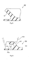
- FIGS. 3 and 4 show the second embodiment.
- a structure of providing a large number of minute concavities and convexities by giving a satin finish to the surface of a lip is shown.
- a structure when grid-like convexities are provided to the surface of the lip is shown.
- Other structures and operations are the same as those of the first embodiment and thus, a description of the same component is omitted when appropriate.
- the basic structure of the lip 31 in the present embodiment is the same as that of the lip 31 shown in the first embodiment.
- the lip 31 in the present embodiment is different from that in the first embodiment only in that grid-like convexities 36 and 37 are provided in an area ranging from the lip tip 31a to the vicinity of the root of the lip on the surface on the one area (O) side. Accordingly, the grid-like convexities 36 or the grid-like convexities 37 are provided to the whole area of the lip 31 that could be brought into contact with the opposed face 72.
- the grid shape of the convexities 36 of the example shown in FIG. 3 is square, that of the convexities 37 of the example shown in FIG. 4 is rhomboidal.
- the grid shape can take, as these examples show, a suitable shape.
- the height, area of one grid and the like of the convexities 36 and 37 may be suitably set according to an environment of use (such as the oil pressure and oil type (viscosity)).
Landscapes
- Engineering & Computer Science (AREA)
- General Engineering & Computer Science (AREA)
- Mechanical Engineering (AREA)
- Check Valves (AREA)
- Fluid-Damping Devices (AREA)
Applications Claiming Priority (1)
| Application Number | Priority Date | Filing Date | Title |
|---|---|---|---|
| JP2007320588A JP2009144763A (ja) | 2007-12-12 | 2007-12-12 | 逆止弁 |
Publications (3)
| Publication Number | Publication Date |
|---|---|
| EP2071218A2 true EP2071218A2 (de) | 2009-06-17 |
| EP2071218A3 EP2071218A3 (de) | 2011-02-16 |
| EP2071218B1 EP2071218B1 (de) | 2013-02-27 |
Family
ID=40427900
Family Applications (1)
| Application Number | Title | Priority Date | Filing Date |
|---|---|---|---|
| EP20080171348 Expired - Fee Related EP2071218B1 (de) | 2007-12-12 | 2008-12-11 | Stossdämpfer mit Rückschlagventil |
Country Status (3)
| Country | Link |
|---|---|
| US (1) | US20090151799A1 (de) |
| EP (1) | EP2071218B1 (de) |
| JP (1) | JP2009144763A (de) |
Families Citing this family (4)
| Publication number | Priority date | Publication date | Assignee | Title |
|---|---|---|---|---|
| JP4972518B2 (ja) * | 2007-10-24 | 2012-07-11 | カヤバ工業株式会社 | チェック構造 |
| CN102788109A (zh) * | 2012-08-16 | 2012-11-21 | 上海汇众萨克斯减振器有限公司 | 一种用于减振器的双弹簧油封 |
| JP6649818B2 (ja) * | 2016-03-14 | 2020-02-19 | 光洋シーリングテクノ株式会社 | 密封部材 |
| JP2017187099A (ja) * | 2016-04-05 | 2017-10-12 | リンナイ株式会社 | 逆止弁 |
Citations (3)
| Publication number | Priority date | Publication date | Assignee | Title |
|---|---|---|---|---|
| JPH053739U (ja) | 1991-06-29 | 1993-01-22 | エヌオーケー株式会社 | 逆止弁 |
| JPH11108101A (ja) | 1997-10-09 | 1999-04-20 | Arai Pump Mfg Co Ltd | 油圧緩衝器用シール |
| JPH11210803A (ja) | 1998-01-23 | 1999-08-03 | Nok Corp | 逆止弁及び密封装置 |
Family Cites Families (9)
| Publication number | Priority date | Publication date | Assignee | Title |
|---|---|---|---|---|
| US4527673A (en) * | 1982-09-16 | 1985-07-09 | Chicago Rawhide Manufacturing Company | Multi-purpose fluid seal for movement control dampers and the like |
| US5579814A (en) * | 1994-03-17 | 1996-12-03 | Monroe Auto Equipment Company | Method and apparatus for charging dampers with pressurized gas |
| JP2749789B2 (ja) * | 1995-03-23 | 1998-05-13 | 日機装株式会社 | 加圧成形装置 |
| JPH09317914A (ja) * | 1996-05-29 | 1997-12-12 | Nok Corp | 逆止弁及び密封装置 |
| JP2000120876A (ja) * | 1998-10-20 | 2000-04-28 | Nsk Ltd | 軸受ユニットの軸封装置 |
| JP2002188730A (ja) * | 2000-12-25 | 2002-07-05 | Showa Corp | 往復動用オイルシールのダストリップ構造 |
| WO2005068277A1 (ja) * | 2004-01-15 | 2005-07-28 | Nsk Ltd. | ステアリングシャフト用ダストカバー |
| JP2005240832A (ja) * | 2004-02-24 | 2005-09-08 | Kayaba Ind Co Ltd | 油圧緩衝器 |
| JP2006242373A (ja) * | 2004-09-24 | 2006-09-14 | Nok Corp | 密封装置 |
-
2007
- 2007-12-12 JP JP2007320588A patent/JP2009144763A/ja active Pending
-
2008
- 2008-12-11 EP EP20080171348 patent/EP2071218B1/de not_active Expired - Fee Related
- 2008-12-11 US US12/332,731 patent/US20090151799A1/en not_active Abandoned
Patent Citations (3)
| Publication number | Priority date | Publication date | Assignee | Title |
|---|---|---|---|---|
| JPH053739U (ja) | 1991-06-29 | 1993-01-22 | エヌオーケー株式会社 | 逆止弁 |
| JPH11108101A (ja) | 1997-10-09 | 1999-04-20 | Arai Pump Mfg Co Ltd | 油圧緩衝器用シール |
| JPH11210803A (ja) | 1998-01-23 | 1999-08-03 | Nok Corp | 逆止弁及び密封装置 |
Also Published As
| Publication number | Publication date |
|---|---|
| EP2071218A3 (de) | 2011-02-16 |
| JP2009144763A (ja) | 2009-07-02 |
| US20090151799A1 (en) | 2009-06-18 |
| EP2071218B1 (de) | 2013-02-27 |
Similar Documents
| Publication | Publication Date | Title |
|---|---|---|
| US4508020A (en) | Multi-function fluid seal for dampers and the like | |
| US4527673A (en) | Multi-purpose fluid seal for movement control dampers and the like | |
| CN108533659A (zh) | 一种机械式自动调节压强黏滞阻尼器 | |
| EP2071218B1 (de) | Stossdämpfer mit Rückschlagventil | |
| JPWO2016067733A1 (ja) | 緩衝器およびその製造方法 | |
| KR20140114050A (ko) | 완충기의 감쇠 밸브 | |
| KR20100066360A (ko) | 체크밸브 | |
| CN101418841A (zh) | 液压减震器用止回密封结构 | |
| JPWO2020095806A1 (ja) | 緩衝器 | |
| EP2992241B1 (de) | Kompressionsresistente stossdämpferkolbendichtung | |
| EP3214337A1 (de) | Stossdämpfer | |
| JP6238962B2 (ja) | 緩衝器における改良 | |
| JP2013204792A (ja) | 緩衝器 | |
| EP3333446A1 (de) | Ventilanordnung für dämpfer | |
| EP1586835A3 (de) | Steuerventil | |
| JP2011214633A (ja) | シリンダ装置 | |
| CN205559961U (zh) | 调温阀 | |
| CN109477542A (zh) | 液压阻尼支承 | |
| JP2009024726A (ja) | 空圧緩衝器 | |
| KR100572005B1 (ko) | 유압댐퍼 | |
| JPH11257523A (ja) | 高圧電磁弁 | |
| CN100523574C (zh) | 具有液压密封的密封圈的限压阀 | |
| JP2010159857A (ja) | 液圧緩衝器 | |
| JP4898608B2 (ja) | 空圧緩衝器 | |
| JPS6131559Y2 (de) |
Legal Events
| Date | Code | Title | Description |
|---|---|---|---|
| PUAI | Public reference made under article 153(3) epc to a published international application that has entered the european phase |
Free format text: ORIGINAL CODE: 0009012 |
|
| AK | Designated contracting states |
Kind code of ref document: A2 Designated state(s): AT BE BG CH CY CZ DE DK EE ES FI FR GB GR HR HU IE IS IT LI LT LU LV MC MT NL NO PL PT RO SE SI SK TR |
|
| AX | Request for extension of the european patent |
Extension state: AL BA MK RS |
|
| PUAL | Search report despatched |
Free format text: ORIGINAL CODE: 0009013 |
|
| AK | Designated contracting states |
Kind code of ref document: A3 Designated state(s): AT BE BG CH CY CZ DE DK EE ES FI FR GB GR HR HU IE IS IT LI LT LU LV MC MT NL NO PL PT RO SE SI SK TR |
|
| AX | Request for extension of the european patent |
Extension state: AL BA MK RS |
|
| 17P | Request for examination filed |
Effective date: 20110429 |
|
| 17Q | First examination report despatched |
Effective date: 20110802 |
|
| AKX | Designation fees paid |
Designated state(s): DE |
|
| GRAP | Despatch of communication of intention to grant a patent |
Free format text: ORIGINAL CODE: EPIDOSNIGR1 |
|
| GRAS | Grant fee paid |
Free format text: ORIGINAL CODE: EPIDOSNIGR3 |
|
| GRAA | (expected) grant |
Free format text: ORIGINAL CODE: 0009210 |
|
| AK | Designated contracting states |
Kind code of ref document: B1 Designated state(s): DE |
|
| REG | Reference to a national code |
Ref country code: DE Ref legal event code: R096 Ref document number: 602008022456 Country of ref document: DE Effective date: 20130425 |
|
| PLBE | No opposition filed within time limit |
Free format text: ORIGINAL CODE: 0009261 |
|
| STAA | Information on the status of an ep patent application or granted ep patent |
Free format text: STATUS: NO OPPOSITION FILED WITHIN TIME LIMIT |
|
| 26N | No opposition filed |
Effective date: 20131128 |
|
| REG | Reference to a national code |
Ref country code: DE Ref legal event code: R097 Ref document number: 602008022456 Country of ref document: DE Effective date: 20131128 |
|
| PGFP | Annual fee paid to national office [announced via postgrant information from national office to epo] |
Ref country code: DE Payment date: 20191126 Year of fee payment: 12 |
|
| REG | Reference to a national code |
Ref country code: DE Ref legal event code: R119 Ref document number: 602008022456 Country of ref document: DE |
|
| PG25 | Lapsed in a contracting state [announced via postgrant information from national office to epo] |
Ref country code: DE Free format text: LAPSE BECAUSE OF NON-PAYMENT OF DUE FEES Effective date: 20210701 |