EP2068048B1 - Dispositif de changement de vitesse - Google Patents
Dispositif de changement de vitesse Download PDFInfo
- Publication number
- EP2068048B1 EP2068048B1 EP07828581A EP07828581A EP2068048B1 EP 2068048 B1 EP2068048 B1 EP 2068048B1 EP 07828581 A EP07828581 A EP 07828581A EP 07828581 A EP07828581 A EP 07828581A EP 2068048 B1 EP2068048 B1 EP 2068048B1
- Authority
- EP
- European Patent Office
- Prior art keywords
- clutch
- hydraulic pressure
- cam
- section
- oil
- Prior art date
- Legal status (The legal status is an assumption and is not a legal conclusion. Google has not performed a legal analysis and makes no representation as to the accuracy of the status listed.)
- Expired - Fee Related
Links
Images


Classifications
-
- F—MECHANICAL ENGINEERING; LIGHTING; HEATING; WEAPONS; BLASTING
- F16—ENGINEERING ELEMENTS AND UNITS; GENERAL MEASURES FOR PRODUCING AND MAINTAINING EFFECTIVE FUNCTIONING OF MACHINES OR INSTALLATIONS; THERMAL INSULATION IN GENERAL
- F16H—GEARING
- F16H63/00—Control outputs from the control unit to change-speed- or reversing-gearings for conveying rotary motion or to other devices than the final output mechanism
- F16H63/02—Final output mechanisms therefor; Actuating means for the final output mechanisms
- F16H63/08—Multiple final output mechanisms being moved by a single common final actuating mechanism
- F16H63/16—Multiple final output mechanisms being moved by a single common final actuating mechanism the final output mechanisms being successively actuated by progressive movement of the final actuating mechanism
- F16H63/18—Multiple final output mechanisms being moved by a single common final actuating mechanism the final output mechanisms being successively actuated by progressive movement of the final actuating mechanism the final actuating mechanism comprising cams
-
- F—MECHANICAL ENGINEERING; LIGHTING; HEATING; WEAPONS; BLASTING
- F16—ENGINEERING ELEMENTS AND UNITS; GENERAL MEASURES FOR PRODUCING AND MAINTAINING EFFECTIVE FUNCTIONING OF MACHINES OR INSTALLATIONS; THERMAL INSULATION IN GENERAL
- F16H—GEARING
- F16H61/00—Control functions within control units of change-speed- or reversing-gearings for conveying rotary motion ; Control of exclusively fluid gearing, friction gearing, gearings with endless flexible members or other particular types of gearing
- F16H61/26—Generation or transmission of movements for final actuating mechanisms
- F16H61/28—Generation or transmission of movements for final actuating mechanisms with at least one movement of the final actuating mechanism being caused by a non-mechanical force, e.g. power-assisted
- F16H2061/2892—Generation or transmission of movements for final actuating mechanisms with at least one movement of the final actuating mechanism being caused by a non-mechanical force, e.g. power-assisted other gears, e.g. worm gears, for transmitting rotary motion to the output mechanism
-
- F—MECHANICAL ENGINEERING; LIGHTING; HEATING; WEAPONS; BLASTING
- F16—ENGINEERING ELEMENTS AND UNITS; GENERAL MEASURES FOR PRODUCING AND MAINTAINING EFFECTIVE FUNCTIONING OF MACHINES OR INSTALLATIONS; THERMAL INSULATION IN GENERAL
- F16H—GEARING
- F16H61/00—Control functions within control units of change-speed- or reversing-gearings for conveying rotary motion ; Control of exclusively fluid gearing, friction gearing, gearings with endless flexible members or other particular types of gearing
- F16H61/26—Generation or transmission of movements for final actuating mechanisms
- F16H61/28—Generation or transmission of movements for final actuating mechanisms with at least one movement of the final actuating mechanism being caused by a non-mechanical force, e.g. power-assisted
- F16H61/32—Electric motors actuators or related electrical control means therefor
-
- F—MECHANICAL ENGINEERING; LIGHTING; HEATING; WEAPONS; BLASTING
- F16—ENGINEERING ELEMENTS AND UNITS; GENERAL MEASURES FOR PRODUCING AND MAINTAINING EFFECTIVE FUNCTIONING OF MACHINES OR INSTALLATIONS; THERMAL INSULATION IN GENERAL
- F16H—GEARING
- F16H61/00—Control functions within control units of change-speed- or reversing-gearings for conveying rotary motion ; Control of exclusively fluid gearing, friction gearing, gearings with endless flexible members or other particular types of gearing
- F16H61/68—Control functions within control units of change-speed- or reversing-gearings for conveying rotary motion ; Control of exclusively fluid gearing, friction gearing, gearings with endless flexible members or other particular types of gearing specially adapted for stepped gearings
- F16H61/684—Control functions within control units of change-speed- or reversing-gearings for conveying rotary motion ; Control of exclusively fluid gearing, friction gearing, gearings with endless flexible members or other particular types of gearing specially adapted for stepped gearings without interruption of drive
- F16H61/688—Control functions within control units of change-speed- or reversing-gearings for conveying rotary motion ; Control of exclusively fluid gearing, friction gearing, gearings with endless flexible members or other particular types of gearing specially adapted for stepped gearings without interruption of drive with two inputs, e.g. selection of one of two torque-flow paths by clutches
-
- Y—GENERAL TAGGING OF NEW TECHNOLOGICAL DEVELOPMENTS; GENERAL TAGGING OF CROSS-SECTIONAL TECHNOLOGIES SPANNING OVER SEVERAL SECTIONS OF THE IPC; TECHNICAL SUBJECTS COVERED BY FORMER USPC CROSS-REFERENCE ART COLLECTIONS [XRACs] AND DIGESTS
- Y10—TECHNICAL SUBJECTS COVERED BY FORMER USPC
- Y10T—TECHNICAL SUBJECTS COVERED BY FORMER US CLASSIFICATION
- Y10T74/00—Machine element or mechanism
- Y10T74/20—Control lever and linkage systems
- Y10T74/20012—Multiple controlled elements
- Y10T74/20018—Transmission control
- Y10T74/20177—Particular element [e.g., shift fork, template, etc.]
Abstract
Claims (2)
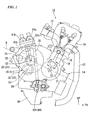
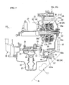
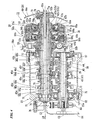
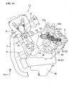
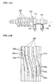
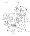
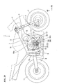
- Dispositif de changement de vitesse utilisé dans une transmission (23) d'un moteur (13), comprenant :un tambour de changement de vitesse (24a) qui change un étage de changement de vitesse de la transmission (23) selon une position angulaire autour d'un axe (C6) ;un actionneur (124) ayant un arbre d'entraînement (125) sensiblement orthogonal par rapport au tambour de changement de vitesse (24a) ;un tambour à rainures en forme de vis sans fin (122) qui est agencé parallèlement à l'arbre d'entraînement (125) de l'actionneur (124) et qui a une pluralité de rainures de came (129) sur sa circonférence externe ;un engrenage de roue (121) qui est fixé de manière coaxiale sur le tambour de changement de vitesse (24a) ; etun dispositif de détection (131, 133, 134) qui détecte une position angulaire du tambour à rainures (122), dans lequel :le tambour de changement de vitesse (24a) est entraîné en rotation par l'actionneur (124) par l'intermédiaire du tambour à rainures (122) et l'engrenage de roue (121), pour changer ainsi l'étage de changement de vitesse de la transmission (23),caractérisé en ce que :l'engrenage de roue (121) a une pluralité de broches sur sa circonférence externe ;au moins une paire de chaque broche (121a) de l'engrenage de roue (121) et chaque rainure de came (129) du tambour à rainures (122) sont mises en prise entre elles ; etle dispositif de détection (131, 133, 134) a une came (131) réalisée de manière intégrale avec une circonférence externe du tambour à rainures (122).
- Dispositif de changement de vitesse selon la revendication 1, dans lequel :le dispositif de détection a deux capteurs indépendants (133, 134) correspondant à la came (131), qui sont agencés avec une différence de phase prédéterminée selon une direction de rotation du tambour à rainures (122).
Applications Claiming Priority (2)
| Application Number | Priority Date | Filing Date | Title |
|---|---|---|---|
| JP2006270103A JP4791314B2 (ja) | 2006-09-29 | 2006-09-29 | ギヤシフト装置 |
| PCT/JP2007/068835 WO2008038724A1 (fr) | 2006-09-29 | 2007-09-27 | Dispositif de changement de vitesse |
Publications (3)
| Publication Number | Publication Date |
|---|---|
| EP2068048A1 EP2068048A1 (fr) | 2009-06-10 |
| EP2068048A4 EP2068048A4 (fr) | 2009-10-21 |
| EP2068048B1 true EP2068048B1 (fr) | 2010-12-01 |
Family
ID=39230159
Family Applications (1)
| Application Number | Title | Priority Date | Filing Date |
|---|---|---|---|
| EP07828581A Expired - Fee Related EP2068048B1 (fr) | 2006-09-29 | 2007-09-27 | Dispositif de changement de vitesse |
Country Status (7)
| Country | Link |
|---|---|
| US (1) | US8015895B2 (fr) |
| EP (1) | EP2068048B1 (fr) |
| JP (1) | JP4791314B2 (fr) |
| CN (1) | CN101517281B (fr) |
| DE (1) | DE602007010958D1 (fr) |
| ES (1) | ES2354846T3 (fr) |
| WO (1) | WO2008038724A1 (fr) |
Families Citing this family (21)
| Publication number | Priority date | Publication date | Assignee | Title |
|---|---|---|---|---|
| JP4800167B2 (ja) * | 2006-09-29 | 2011-10-26 | 本田技研工業株式会社 | ギヤシフト装置 |
| JP4719659B2 (ja) * | 2006-09-29 | 2011-07-06 | 本田技研工業株式会社 | 車両用変速機の変速制御装置 |
| JP4648280B2 (ja) * | 2006-09-29 | 2011-03-09 | 本田技研工業株式会社 | 自動二輪車用変速機の変速制御装置 |
| JP4998728B2 (ja) * | 2007-09-28 | 2012-08-15 | 本田技研工業株式会社 | ツインクラッチ式変速装置 |
| JP2009162278A (ja) * | 2007-12-28 | 2009-07-23 | Honda Motor Co Ltd | 変速装置のシフトドラム駆動装置 |
| JP4895996B2 (ja) * | 2007-12-27 | 2012-03-14 | 本田技研工業株式会社 | ツインクラッチ式変速装置 |
| ITTO20080034A1 (it) * | 2008-01-16 | 2009-07-17 | Automac Di Bigi Ing Maurizio Sas | Dispositivo di comando per l'innesto delle marce per un cambio di velocita' di un veicolo con tamburo rotante presentante una camma principale e una camma ausiliaria |
| KR101047649B1 (ko) | 2009-11-12 | 2011-07-07 | 현대자동차주식회사 | 자동화 수동변속기의 변속장치 |
| JP5570940B2 (ja) * | 2010-10-26 | 2014-08-13 | 本田技研工業株式会社 | 鞍乗り型車両 |
| US9086132B2 (en) * | 2012-03-30 | 2015-07-21 | Honda Motor Co., Ltd. | Vehicle transmission |
| JP6160063B2 (ja) * | 2012-10-31 | 2017-07-12 | スズキ株式会社 | 変速機用ギヤシフト装置 |
| EP2818768B1 (fr) * | 2013-06-28 | 2019-01-09 | Honda Motor Co., Ltd. | Dispositif de détection de position de commutateur |
| JP6032613B2 (ja) * | 2013-06-28 | 2016-11-30 | 本田技研工業株式会社 | シフト位置検出装置 |
| WO2016199156A1 (fr) * | 2015-06-08 | 2016-12-15 | Lml Ltd. | Moteur à changement de vitesse motorisé et embrayage à actionnement à force faible pour deux-roues |
| JP6575244B2 (ja) * | 2015-09-04 | 2019-09-18 | スズキ株式会社 | 多段式変速システム |
| JP6641810B2 (ja) * | 2015-09-08 | 2020-02-05 | スズキ株式会社 | 車両用の変速システム |
| US10982765B2 (en) * | 2016-11-11 | 2021-04-20 | Team Industries, Inc. | Dual cam spring-loaded shifting transmission assembly |
| IT201600122071A1 (it) * | 2016-12-01 | 2018-06-01 | Piaggio & C Spa | Trasmissione sincrona a elevato rendimento |
| US10458523B2 (en) * | 2017-07-26 | 2019-10-29 | Hall Labs Llc | Automatic gear-shifting device |
| CN209524062U (zh) | 2019-01-29 | 2019-10-22 | 浙江春风动力股份有限公司 | 一种花键齿、齿轮接合机构及变速箱 |
| CN209654588U (zh) | 2019-01-29 | 2019-11-19 | 浙江春风动力股份有限公司 | 一种变速鼓、发动机及摩托车 |
Family Cites Families (17)
| Publication number | Priority date | Publication date | Assignee | Title |
|---|---|---|---|---|
| US2525240A (en) * | 1947-03-04 | 1950-10-10 | Harry W Pierce | Steering gear |
| US3049017A (en) | 1959-02-04 | 1962-08-14 | Commercial Cam & Machine Co | Indexing cam structure |
| FR1327537A (fr) | 1962-06-30 | 1963-05-17 | English Electric Co Ltd | Mécanisme d'entraînement et d'avance jusqu'à des positions d'arrêt |
| US4664217A (en) * | 1984-12-24 | 1987-05-12 | United Technologies Electro Systems, Inc. | Electric shift actuator for vehicle transfer case |
| JP3044498B2 (ja) * | 1991-08-02 | 2000-05-22 | 本田技研工業株式会社 | 変速装置のシフトドラム駆動機構 |
| JPH0835553A (ja) * | 1994-07-27 | 1996-02-06 | Mitsuhashi Seisakusho:Kk | 運動変換装置 |
| JP3853926B2 (ja) | 1997-09-12 | 2006-12-06 | 本田技研工業株式会社 | 車両用動力伝達装置 |
| JP3935579B2 (ja) * | 1997-10-29 | 2007-06-27 | 富士機械製造株式会社 | カバーテープ送り装置,カバーテープ処理装置およびフィーダユニット |
| JP4641574B2 (ja) * | 1999-08-06 | 2011-03-02 | ヤマハモーターエレクトロニクス株式会社 | 自動二輪車用の電動式変速機切換え装置 |
| CN2417051Y (zh) * | 2000-04-07 | 2001-01-31 | 韦寿银 | 全自动换挡变速器 |
| JP4322588B2 (ja) | 2003-07-23 | 2009-09-02 | 本田技研工業株式会社 | シフトドラム変速機 |
| US7096753B2 (en) * | 2003-07-23 | 2006-08-29 | Honda Motor Co., Ltd. | Engine having a cartridge type transmission |
| JP2005249488A (ja) * | 2004-03-02 | 2005-09-15 | Denso Corp | 回転センサの検出信号処理回路及び検出信号処理装置 |
| JP4519550B2 (ja) * | 2004-07-14 | 2010-08-04 | 本田技研工業株式会社 | 変速装置 |
| JP4800167B2 (ja) * | 2006-09-29 | 2011-10-26 | 本田技研工業株式会社 | ギヤシフト装置 |
| JP5020765B2 (ja) * | 2007-09-29 | 2012-09-05 | 本田技研工業株式会社 | 自動二輪車用パワーユニット |
| EP2075435B1 (fr) * | 2007-12-28 | 2017-12-13 | Honda Motor Co., Ltd. | Moteur à combustion interne |
-
2006
- 2006-09-29 JP JP2006270103A patent/JP4791314B2/ja not_active Expired - Fee Related
-
2007
- 2007-09-27 EP EP07828581A patent/EP2068048B1/fr not_active Expired - Fee Related
- 2007-09-27 WO PCT/JP2007/068835 patent/WO2008038724A1/fr active Application Filing
- 2007-09-27 DE DE602007010958T patent/DE602007010958D1/de active Active
- 2007-09-27 CN CN200780035515.3A patent/CN101517281B/zh not_active Expired - Fee Related
- 2007-09-27 US US12/443,300 patent/US8015895B2/en not_active Expired - Fee Related
- 2007-09-27 ES ES07828581T patent/ES2354846T3/es active Active
Also Published As
| Publication number | Publication date |
|---|---|
| CN101517281A (zh) | 2009-08-26 |
| US20100107796A1 (en) | 2010-05-06 |
| EP2068048A4 (fr) | 2009-10-21 |
| JP4791314B2 (ja) | 2011-10-12 |
| CN101517281B (zh) | 2013-01-16 |
| DE602007010958D1 (de) | 2011-01-13 |
| ES2354846T3 (es) | 2011-03-18 |
| JP2008089068A (ja) | 2008-04-17 |
| EP2068048A1 (fr) | 2009-06-10 |
| WO2008038724A1 (fr) | 2008-04-03 |
| US8015895B2 (en) | 2011-09-13 |
Similar Documents
| Publication | Publication Date | Title |
|---|---|---|
| EP2068048B1 (fr) | Dispositif de changement de vitesse | |
| EP2068049B1 (fr) | Dispositif de changement de vitesse | |
| EP2068030B1 (fr) | Dispositif d'embrayage double | |
| US8196485B2 (en) | Twin clutch device | |
| EP1906056B1 (fr) | Transmission de type embrayage double | |
| US8166840B2 (en) | Twin clutch type speed change control system | |
| US8057359B2 (en) | Twin clutch type speed change control system | |
| US8371987B2 (en) | Automatic speed change control system for vehicle | |
| EP2068029B1 (fr) | Dispositif d'embrayage double | |
| WO2009096362A1 (fr) | Dispositif d'embrayage | |
| US8235868B2 (en) | Clutch control apparatus for vehicle |
Legal Events
| Date | Code | Title | Description |
|---|---|---|---|
| PUAI | Public reference made under article 153(3) epc to a published international application that has entered the european phase |
Free format text: ORIGINAL CODE: 0009012 |
|
| 17P | Request for examination filed |
Effective date: 20090331 |
|
| AK | Designated contracting states |
Kind code of ref document: A1 Designated state(s): DE ES |
|
| AX | Request for extension of the european patent |
Extension state: AL BA HR MK RS |
|
| RIN1 | Information on inventor provided before grant (corrected) |
Inventor name: TSUKADA, YOSHIAKI Inventor name: TOMODA, AKIHIKO |
|
| A4 | Supplementary search report drawn up and despatched |
Effective date: 20090917 |
|
| 17Q | First examination report despatched |
Effective date: 20091006 |
|
| DAX | Request for extension of the european patent (deleted) | ||
| GRAP | Despatch of communication of intention to grant a patent |
Free format text: ORIGINAL CODE: EPIDOSNIGR1 |
|
| RIC1 | Information provided on ipc code assigned before grant |
Ipc: F16H 63/18 20060101AFI20100315BHEP |
|
| GRAS | Grant fee paid |
Free format text: ORIGINAL CODE: EPIDOSNIGR3 |
|
| GRAA | (expected) grant |
Free format text: ORIGINAL CODE: 0009210 |
|
| AK | Designated contracting states |
Kind code of ref document: B1 Designated state(s): DE ES |
|
| REF | Corresponds to: |
Ref document number: 602007010958 Country of ref document: DE Date of ref document: 20110113 Kind code of ref document: P |
|
| REG | Reference to a national code |
Ref country code: ES Ref legal event code: FG2A Effective date: 20110308 |
|
| PLBE | No opposition filed within time limit |
Free format text: ORIGINAL CODE: 0009261 |
|
| STAA | Information on the status of an ep patent application or granted ep patent |
Free format text: STATUS: NO OPPOSITION FILED WITHIN TIME LIMIT |
|
| 26N | No opposition filed |
Effective date: 20110902 |
|
| REG | Reference to a national code |
Ref country code: DE Ref legal event code: R097 Ref document number: 602007010958 Country of ref document: DE Effective date: 20110902 |
|
| PGFP | Annual fee paid to national office [announced via postgrant information from national office to epo] |
Ref country code: DE Payment date: 20120919 Year of fee payment: 6 |
|
| PGFP | Annual fee paid to national office [announced via postgrant information from national office to epo] |
Ref country code: ES Payment date: 20121004 Year of fee payment: 6 |
|
| REG | Reference to a national code |
Ref country code: DE Ref legal event code: R119 Ref document number: 602007010958 Country of ref document: DE Effective date: 20140401 |
|
| PG25 | Lapsed in a contracting state [announced via postgrant information from national office to epo] |
Ref country code: DE Free format text: LAPSE BECAUSE OF NON-PAYMENT OF DUE FEES Effective date: 20140401 |
|
| REG | Reference to a national code |
Ref country code: ES Ref legal event code: FD2A Effective date: 20150708 |
|
| PG25 | Lapsed in a contracting state [announced via postgrant information from national office to epo] |
Ref country code: ES Free format text: LAPSE BECAUSE OF NON-PAYMENT OF DUE FEES Effective date: 20130928 |