WO2009096362A1 - Dispositif d'embrayage - Google Patents
Dispositif d'embrayage Download PDFInfo
- Publication number
- WO2009096362A1 WO2009096362A1 PCT/JP2009/051203 JP2009051203W WO2009096362A1 WO 2009096362 A1 WO2009096362 A1 WO 2009096362A1 JP 2009051203 W JP2009051203 W JP 2009051203W WO 2009096362 A1 WO2009096362 A1 WO 2009096362A1
- Authority
- WO
- WIPO (PCT)
- Prior art keywords
- clutch
- hydraulic
- oil
- hydraulic pressure
- oil passage
- Prior art date
Links
Images


Classifications
-
- F—MECHANICAL ENGINEERING; LIGHTING; HEATING; WEAPONS; BLASTING
- F16—ENGINEERING ELEMENTS AND UNITS; GENERAL MEASURES FOR PRODUCING AND MAINTAINING EFFECTIVE FUNCTIONING OF MACHINES OR INSTALLATIONS; THERMAL INSULATION IN GENERAL
- F16D—COUPLINGS FOR TRANSMITTING ROTATION; CLUTCHES; BRAKES
- F16D25/00—Fluid-actuated clutches
- F16D25/06—Fluid-actuated clutches in which the fluid actuates a piston incorporated in, i.e. rotating with the clutch
- F16D25/062—Fluid-actuated clutches in which the fluid actuates a piston incorporated in, i.e. rotating with the clutch the clutch having friction surfaces
- F16D25/063—Fluid-actuated clutches in which the fluid actuates a piston incorporated in, i.e. rotating with the clutch the clutch having friction surfaces with clutch members exclusively moving axially
- F16D25/0635—Fluid-actuated clutches in which the fluid actuates a piston incorporated in, i.e. rotating with the clutch the clutch having friction surfaces with clutch members exclusively moving axially with flat friction surfaces, e.g. discs
- F16D25/0638—Fluid-actuated clutches in which the fluid actuates a piston incorporated in, i.e. rotating with the clutch the clutch having friction surfaces with clutch members exclusively moving axially with flat friction surfaces, e.g. discs with more than two discs, e.g. multiple lamellae
-
- F—MECHANICAL ENGINEERING; LIGHTING; HEATING; WEAPONS; BLASTING
- F16—ENGINEERING ELEMENTS AND UNITS; GENERAL MEASURES FOR PRODUCING AND MAINTAINING EFFECTIVE FUNCTIONING OF MACHINES OR INSTALLATIONS; THERMAL INSULATION IN GENERAL
- F16D—COUPLINGS FOR TRANSMITTING ROTATION; CLUTCHES; BRAKES
- F16D25/00—Fluid-actuated clutches
- F16D25/10—Clutch systems with a plurality of fluid-actuated clutches
-
- F—MECHANICAL ENGINEERING; LIGHTING; HEATING; WEAPONS; BLASTING
- F16—ENGINEERING ELEMENTS AND UNITS; GENERAL MEASURES FOR PRODUCING AND MAINTAINING EFFECTIVE FUNCTIONING OF MACHINES OR INSTALLATIONS; THERMAL INSULATION IN GENERAL
- F16D—COUPLINGS FOR TRANSMITTING ROTATION; CLUTCHES; BRAKES
- F16D25/00—Fluid-actuated clutches
- F16D25/12—Details not specific to one of the before-mentioned types
-
- F—MECHANICAL ENGINEERING; LIGHTING; HEATING; WEAPONS; BLASTING
- F16—ENGINEERING ELEMENTS AND UNITS; GENERAL MEASURES FOR PRODUCING AND MAINTAINING EFFECTIVE FUNCTIONING OF MACHINES OR INSTALLATIONS; THERMAL INSULATION IN GENERAL
- F16D—COUPLINGS FOR TRANSMITTING ROTATION; CLUTCHES; BRAKES
- F16D48/00—External control of clutches
- F16D48/02—Control by fluid pressure
- F16D48/0206—Control by fluid pressure in a system with a plurality of fluid-actuated clutches
-
- F—MECHANICAL ENGINEERING; LIGHTING; HEATING; WEAPONS; BLASTING
- F16—ENGINEERING ELEMENTS AND UNITS; GENERAL MEASURES FOR PRODUCING AND MAINTAINING EFFECTIVE FUNCTIONING OF MACHINES OR INSTALLATIONS; THERMAL INSULATION IN GENERAL
- F16D—COUPLINGS FOR TRANSMITTING ROTATION; CLUTCHES; BRAKES
- F16D21/00—Systems comprising a plurality of actuated clutches
- F16D21/02—Systems comprising a plurality of actuated clutches for interconnecting three or more shafts or other transmission members in different ways
- F16D21/06—Systems comprising a plurality of actuated clutches for interconnecting three or more shafts or other transmission members in different ways at least two driving shafts or two driven shafts being concentric
- F16D2021/0661—Hydraulically actuated multiple lamellae clutches
-
- F—MECHANICAL ENGINEERING; LIGHTING; HEATING; WEAPONS; BLASTING
- F16—ENGINEERING ELEMENTS AND UNITS; GENERAL MEASURES FOR PRODUCING AND MAINTAINING EFFECTIVE FUNCTIONING OF MACHINES OR INSTALLATIONS; THERMAL INSULATION IN GENERAL
- F16D—COUPLINGS FOR TRANSMITTING ROTATION; CLUTCHES; BRAKES
- F16D2500/00—External control of clutches by electric or electronic means
- F16D2500/10—System to be controlled
- F16D2500/11—Application
- F16D2500/1107—Vehicles
- F16D2500/1117—Motorcycle
-
- F—MECHANICAL ENGINEERING; LIGHTING; HEATING; WEAPONS; BLASTING
- F16—ENGINEERING ELEMENTS AND UNITS; GENERAL MEASURES FOR PRODUCING AND MAINTAINING EFFECTIVE FUNCTIONING OF MACHINES OR INSTALLATIONS; THERMAL INSULATION IN GENERAL
- F16D—COUPLINGS FOR TRANSMITTING ROTATION; CLUTCHES; BRAKES
- F16D2500/00—External control of clutches by electric or electronic means
- F16D2500/30—Signal inputs
- F16D2500/308—Signal inputs from the transmission
- F16D2500/30806—Engaged transmission ratio
-
- F—MECHANICAL ENGINEERING; LIGHTING; HEATING; WEAPONS; BLASTING
- F16—ENGINEERING ELEMENTS AND UNITS; GENERAL MEASURES FOR PRODUCING AND MAINTAINING EFFECTIVE FUNCTIONING OF MACHINES OR INSTALLATIONS; THERMAL INSULATION IN GENERAL
- F16D—COUPLINGS FOR TRANSMITTING ROTATION; CLUTCHES; BRAKES
- F16D2500/00—External control of clutches by electric or electronic means
- F16D2500/30—Signal inputs
- F16D2500/314—Signal inputs from the user
- F16D2500/31406—Signal inputs from the user input from pedals
Definitions
- the present invention relates to a clutch device used in a transmission of an engine such as a vehicle.
- This application claims priority based on Japanese Patent Application No. 2008-021891 filed in Japan on January 31, 2008, the contents of which are incorporated herein by reference.
- the clutch device disclosed in Patent Document 1 is a hydraulic disc that exerts a predetermined engagement force by displacing a pressing member in the axial direction by an externally supplied hydraulic pressure and applying pressure to a clutch disc supported by a clutch center.
- the pressing member has a connection-side hydraulic chamber that applies a pressing force to the clutch connection side.
- the pressing member has a pressure compensating hydraulic chamber that applies a pressing force to the clutch disengagement side and compensates the pressure of the return operation.
- the pressure is offset by the hydraulic pressure that urges the pressing member toward the clutch disengagement side.
- the pressure compensation hydraulic chamber is formed between the pressing member and the partition member provided inside thereof.
- the gap between the partition member and the clutch inner is an oil passage.
- a part of the clutch hydraulic oil is guided to the outside in the clutch radial direction through this oil passage.
- This hydraulic oil is supplied to the clutch disc through an oil hole formed in the disc support portion of the clutch center.
- the present invention eliminates the influence of centrifugal force on the clutch hydraulic oil during clutch rotation in the clutch device constituting the hydraulic disk clutch, suppresses the increase in the number of parts, volume and weight of the disk clutch, thereby reducing pressure compensation hydraulic pressure.
- One of the purposes is to efficiently supply the indoor hydraulic oil to other parts.
- a clutch device that is used in a transmission of an engine and includes a hydraulic first disk clutch, wherein the first disk clutch is: a clutch radial direction A clutch center having a flange portion extending to the clutch center; a clutch disk supported by the clutch center; a pressing member that is axially displaceable by hydraulic pressure supplied from the outside and presses the clutch disk; and the pressing member A connection-side hydraulic chamber that applies a pressing force to the clutch connection side; and a pressure-compensating hydraulic chamber that applies a pressing force to the clutch disengagement side to compensate the pressure of the return operation.
- the pressure compensation hydraulic chamber is formed between the flange portion and the pressing member, and hydraulic fluid in the pressure compensation hydraulic chamber is guided to the flange portion outside the pressure compensation hydraulic chamber.
- Road is formed, a clutch device, characterized in that the oil passage is open to the pressure compensation hydraulic chamber in the radial direction intermediate portion of the flange portion.
- the above clutch device may be configured as follows: The oil passage extends through the flange portion to a clutch disk support portion on the outer periphery of the clutch center.
- the clutch device may be configured as follows: a second disk clutch disposed coaxially and adjacent to the first disk clutch; and the oil path to each of the disk clutches. Is provided.
- the clutch device of the above (1) when the disk clutch rotates, a hydraulic pressure is generated to urge the pressing member toward the clutch disengagement side in the oil reservoir in the radial direction outside the opening of the oil passage in the pressure compensation hydraulic chamber. Can be made. Further, it is possible to cancel the hydraulic pressure that urges the pressing member generated in the connection-side hydraulic chamber to the clutch connection side. Thereby, the influence of the centrifugal force on the clutch operating oil at the time of clutch rotation can be eliminated and the clutch operating state can be kept good. In addition, a part of the hydraulic oil in the pressure compensation hydraulic chamber can be led out of the hydraulic chamber through the oil passage, and the hydraulic oil can be effectively used for lubrication of other parts.
- each disk clutch in the twin clutch can be reduced in size and weight, and the clutch device can be suitably used for a transmission of an engine of a small vehicle such as a motorcycle. it can.
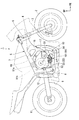
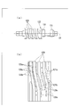
- FIG. 1 is a right side view of a motorcycle according to an embodiment of the present invention.
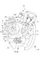
- FIG. 2 is a right side view of the engine of the motorcycle.
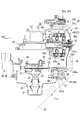
- FIG. 3 is a developed sectional view parallel to the left-right direction showing the main part of the engine.
- FIG. 4 is a sectional view of the twin clutch transmission of the engine.
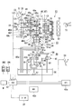
- FIG. 5 is a configuration diagram of the twin clutch transmission.
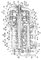
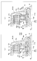
- FIG. 6 is a sectional view of the twin clutch of the twin clutch transmission.
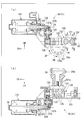
- FIG. 7 is a cross-sectional view corresponding to a part of FIG. Part (a) is an enlarged explanatory view of an oil supply path to the clutch disk of the twin clutch. (B) part is a modification of the oil supply passage.
- FIG. 1 is a right side view of a motorcycle according to an embodiment of the present invention.
- FIG. 2 is a right side view of the engine of the motorcycle.
- FIG. 3 is a developed sectional view parallel to the left-right direction showing the main part of the engine
- FIG. 8 is a side view of a bearing holder for holding a ball bearing supporting the left end portion of each shaft of the twin clutch transmission on the left side wall of the transmission case.
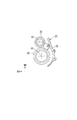
- FIG. 9 is a right side view of the hydraulic cut device of the twin clutch transmission.
- FIG. 10 is a left side view of the engine.
- FIG. 11 is a sectional view of the gear shift device for the engine.
- FIG. 13B is a development view of the cam groove on the outer periphery of the barrel cam.
- FIG. 14 is a diagram showing ON and OFF of the first and second switches with respect to the rotation angle of the barrel cam.
- FIG. 15A is a table showing ON / OFF of each of the switches with respect to the rotation region of the barrel cam.
- (B) part of FIG. 15 is a table
- FIG. 16 is a cross-sectional view corresponding to FIG. 12 showing a modified example of the arrangement of the first and second sensors.
- FIG. 17 is a graph showing the rotation angle and angular velocity of the shift drum with respect to the barrel cam rotation angle of the gear shift device.
- (A) part shows the case where a cam groove continues via a curved part.
- FIG. 18 is a side view corresponding to FIG. 10 showing a modification of the solenoid valve arrangement in the twin clutch transmission.
- FIG. 19 is a side view corresponding to FIG. 10 showing another modification of the solenoid valve arrangement in the twin clutch transmission.
- an upper portion of a front fork 3 that pivotally supports a front wheel 2 of a motorcycle (saddle-type vehicle) 1 is pivoted to a head pipe 6 at a front end portion of a vehicle body frame 5 via a steering stem 4. Be supported.
- a main frame 7 extends rearward from the head pipe 6 and continues to the pivot plate 8.
- the pivot plate 8 pivotally supports the front end of the swing arm 9 so as to be swingable up and down.
- a rear wheel 11 is pivotally supported at the rear end of the swing arm 9.
- a cushion unit 12 is interposed between the swing arm 9 and the vehicle body frame 5.
- An engine (internal combustion engine) 13 that is a prime mover of the motorcycle 1 is mounted on the body frame 5.
- the engine 13 is a parallel four-cylinder engine having the crank axis C1 along the vehicle width direction (left-right direction).
- a cylinder portion 15 is erected on the crankcase 14 of the engine 13.
- An intake system throttle body 16 is connected to the rear part of the cylinder part 15, and an exhaust pipe 17 is connected to the front part.
- a piston 18 corresponding to each cylinder is fitted in the cylinder portion 15 so as to be able to reciprocate, and the reciprocating motion of each piston 18 is converted into rotational motion of the crankshaft 21 via the connecting rod 19.
- a mission case 22 is connected to the rear of the crankcase 14 integrally.
- a twin clutch transmission 23 and a change mechanism 24 are accommodated in the transmission case 22.
- the right side of the mission case 22 is a clutch case 25.
- a twin clutch 26 of the twin clutch transmission 23 is accommodated in the clutch case 25.
- a starter motor 27 is disposed on the mission case 22 (see FIG. 3). The rotational power of the crankshaft 21 is output to the left side of the transmission case 22 via the twin clutch transmission 23 and then transmitted to the rear wheel 11 via, for example, a chain-type power transmission mechanism.
- the main three axes of the crankshaft 21, the main shaft 28 of the twin clutch transmission 23 parallel to the crankshaft 21, and the countershaft 29 are three-dimensionally arranged in the engine 13. ing. Specifically, the axes C1 and C2 of the crankshaft 21 and the main shaft 28 are arranged on a vertically rising and dividing plane B that is rearwardly raised in the crankcase 14. The axis C3 of the countershaft 29 is disposed below the dividing plane B and behind the crankshaft 21. Thereby, the front-rear length of the engine 13 is shortened and the degree of freedom in layout is increased.
- the change mechanism 24 is disposed behind and slightly above the main shaft 28.
- first and second oil pumps 31 and 32 are arranged inside the lower portion of the crankcase 14 so as to share a drive shaft 33 along the left-right direction.
- the first oil pump 31 pumps oil to each part in the engine.
- the discharge port of the first oil pump 31 is connected to a main oil gallery (not shown) via a main oil supply passage 34.
- the second oil pump 32 is a hydraulic pressure generation source for operating the twin clutch 26.
- a discharge port of the second oil pump 32 is connected to a supply oil passage 35 to the twin clutch 26.
- Reference numeral 37 denotes a strainer that extends downward from the oil pumps 31 and 32 and is immersed in the engine oil in the oil pan 36 under the crankcase 14.
- Reference numeral 38 denotes a water pump disposed on the lower right side of the crankcase 14 and having a drive shaft coaxial with the oil pumps 31 and 32.
- the motorcycle 1 includes the twin clutch transmission 23 provided continuously with the engine 13, a gear shift device 41 provided with a drive mechanism 39 in the change mechanism 24, and the twin clutch.
- the automatic transmission system mainly includes an electronic control unit (ECU) 42 that controls the operation of the transmission 23 and the gear shift device 41.
- ECU electronice control unit
- the twin-clutch transmission 23 spans the main shaft 28 having a double structure including inner and outer shafts 43, 44, the counter shaft 29 arranged in parallel with the main shaft 28, and the main shaft 28 and the counter shaft 29.
- the twin clutch 26 coaxially disposed at the right end portion of the main shaft 28, and a hydraulic pressure supply device 46 that supplies the twin clutch 26 with hydraulic pressure for operation thereof.
- an assembly including the main shaft 28, the counter shaft 29, and the transmission gear group 45 may be referred to as a transmission 47.
- the main shaft 28 has a configuration in which the right side portion of the inner shaft 43 extending to the left and right of the mission case 22 is inserted into the outer shaft 44.
- drive gears 48 a to 48 f for six speeds included in the transmission gear group 45 are distributed and arranged.
- driven gears 49 a to 49 f for six speeds included in the transmission gear group 45 are arranged on the outer periphery of the counter shaft 29.
- the corresponding gears mesh with each other to form transmission gear pairs 45a to 45f.
- Each transmission gear pair 45a to 45f corresponds to one gear stage.
- Each of the transmission gear pairs 45a to 45f has a reduction gear ratio that decreases in order from the first speed to the sixth speed (becomes a high speed gear).
- the twin clutch 26 is composed of hydraulic first and second disk clutches (hereinafter simply referred to as clutches) 51a and 51b that are coaxially arranged adjacent to each other.
- the inner and outer shafts 43 and 44 are coaxially connected to the clutches 51a and 51b, respectively.
- Each of the clutches 51 a and 51 b can be individually connected / disconnected depending on whether or not the hydraulic pressure is supplied from the hydraulic pressure supply device 46.
- the change mechanism 24 moves a plurality of shift forks 24b by the rotation of the shift drum 24a arranged in parallel with the shafts 28 and 29, and switches the transmission gear pair used for power transmission to the counter shaft 29.
- the drive mechanism 39 is disposed at the left end of the shift drum 24a. 5 denotes a sensor that detects the operation amount of the drive mechanism 39 for detecting the gear position of the transmission 47.
- the electronic control unit (ECU) 42 includes a throttle grip opening sensor T1, a throttle valve opening sensor T2 of the throttle body 16, and a side stand (or center stand) storage sensor SS.
- a throttle grip opening sensor T1 for example, information from the mode switch SW1 and the shift switch SW2 provided on the handle is collected. Based on these pieces of information, the ECU 42 controls the operation of the twin clutch transmission 23 and the gear shift device 41 to change the gear position (shift position) of the transmission 47.
- the speed change mode selected by the mode switch SW1 is a full automatic mode for automatically changing the gear position based on vehicle driving information such as the vehicle speed and the engine speed, and a gear change only by operating the shift switch SW2 based on the driver's will. Including semi-automatic mode for switching stages.
- the current shift mode and shift speed are appropriately displayed on, for example, the meter device M provided near the handle.
- the ECU 42 appropriately shares information from each sensor with the ECU 42a for the fuel injection device and the ECU 42b for the antilock brake device.
- One of the clutches 51a and 51b is connected and the other is disconnected, and power is transmitted using any of the transmission gear pairs connected to one of the inner and outer shafts 43 and 44.
- a gear to be used next is selected in advance from a pair of transmission gears connected to the other of the inner and outer shafts 43 and 44.
- one of the clutches 51a and 51b is disconnected and the other is connected to switch to power transmission using the previously selected transmission gear pair.
- the transmission 47 is shifted up or down.
- 5 denotes a vehicle speed sensor that detects the number of rotations of the main shaft 28 for vehicle speed detection.
- Reference numeral S3 denotes a rotational speed sensor for detecting the rotational speed of the primary drive gear 58a for detecting the engine rotational speed (crankshaft rotational speed).
- Reference numerals S4 and S5 denote rotational speed sensors for detecting the rotational speeds of the inner and outer shafts 43 and 44, respectively.
- the twin clutch 26 is arranged in the clutch case 25 (hydraulic chamber) with the first disk clutch 51a on the right side (outside in the vehicle width direction) and the second clutch 51b on the left side (in the vehicle width direction). Configured.
- Each of the clutches 51a and 51b is a wet multi-plate clutch having a plurality of clutch plates that are alternately overlapped in the axial direction.
- the right side portion of the clutch case 25 is a clutch cover 69 that is detachably fixed by a plurality of bolts (see FIGS. 3 and 4).
- the first clutch 51 a is disposed near the right outer wall 69 a of the clutch cover 69.
- Each clutch 51a, 51b is a hydraulic type that exerts a predetermined engagement force by displacing the pressure plates 52a, 52b in the axial direction by externally supplied hydraulic pressure.
- Each of the clutches 51a and 51b includes return springs 53a and 53b that urge the pressure plates 52a and 52b toward the clutch disengagement side, and a connection-side hydraulic chamber 54a that applies a pressing force to the clutch connection side on the pressure plates 52a and 52b.
- 54b and the pressure plate 52a, 52b are applied with a pressing force to the clutch disengagement side to compensate for the pressure of the return operation (cancel the increase in the pressing force due to the centrifugal force of each clutch 51a, 51b)
- Each has hydraulic chambers 55a and 55b.
- the hydraulic pressure from the first oil pump 31 always acts on the cutting side hydraulic chambers 55a and 55b in a relatively low pressure state.
- relatively high hydraulic pressure from the hydraulic pressure supply device 46 can be supplied to the connection side hydraulic chambers 54a and 54b.
- the clutches 51a and 51b share a single clutch outer 56 and are configured to have substantially the same diameter.
- the clutch outer 56 has a bottomed cylindrical shape that is released to the right.
- a clutch center 57a for the first clutch 51a is disposed on the inner right side of the clutch outer 56, and a clutch center 57b for the second clutch 51b is disposed on the inner left side.
- the primary driven gear 58 is connected to the left side of the bottom of the clutch outer 56 via a spring damper.
- the primary drive gear 58a of the crankshaft 21 meshes with the primary driven gear 58.
- the hub portion 56a of the clutch outer 56 is supported by the main shaft 28 (outer shaft 44) so as to be relatively rotatable via a needle bearing 56c.
- the clutch outer 56 rotates integrally with the rotation of the crankshaft 21.
- a drive sprocket 56b for driving the oil pumps 31 and 32 is provided so as to be integrally rotatable.
- a plurality of clutch plates 61a for the first clutch 51a are supported on the inner peripheral right side of the outer wall portion of the clutch outer 56, and a plurality of clutch plates 61b for the second clutch 51b are supported on the inner peripheral left side so as not to be relatively rotatable. .
- the central cylinder portion 62a of the clutch center 57a of the first clutch 51a is spline-fitted to the right end portion of the inner shaft 43 protruding rightward from the right end portion of the outer shaft 44 and is integrally fixed by a lock nut 78. .
- the center cylinder part 62a has the structure divided
- a flange portion 64a that extends toward the inner periphery of the outer wall portion of the clutch outer 56 (toward the outer side in the clutch radial direction) is integrally formed on the left side portion of the central cylindrical portion 62a.
- a cylindrical disk support portion 65a is integrally formed on the radially outer side of the flange portion 64a.
- a plurality of clutch disks 66a are supported on the outer periphery of the disk support portion 65a so as not to be relatively rotatable.
- the clutch disks 66a and the clutch plates 61a are alternately overlapped in the clutch axial direction.
- the inner peripheral side of the pressure plate 52a is opposed to the right side of the flange portion 64a with a predetermined gap.
- a stopper ring SR for restricting the leftward movement of each clutch plate 61a and each clutch disk 66a is attached to the left end of the disk support portion 65a, and between this stopper ring SR and the outer peripheral side of the pressure plate 52a.
- the clutch plates 61a and the clutch disks 66a are arranged in a stacked state.
- the cutting-side hydraulic chamber 55a is formed between the inner peripheral side of the pressure plate 52a and the flange portion 64a, and the pressure plate 52a is attached to the right side (the side away from the flange portion 64a, the clutch disengagement side).
- An energizing return spring 53a is provided.
- a support flange portion 67a integrally formed on the outer periphery of the right side portion of the central cylinder portion 62a is disposed opposite to the right side on the inner periphery side of the pressure plate 52a.
- the connection-side hydraulic chamber 54a is formed between the support flange portion 67a and the inner peripheral side of the pressure plate 52a.
- the clutch center 57b of the second clutch 51b has a central cylindrical portion 62b that is spline-fitted to the right end portion of the outer shaft 44 and is integrally fixed by a lock nut 79.
- the center cylinder part 62b also has the structure divided
- a flange 64b that extends toward the inner periphery of the outer wall of the clutch outer 56 (toward the outer side in the clutch radial direction) is integrally formed on the left side of the central cylinder 62b.
- a cylindrical disk support portion 65b is integrally formed on the radially outer side of the flange portion 64b.
- a plurality of clutch disks 66b are supported on the outer periphery of the disk support portion 65b so as not to be relatively rotatable.
- the respective clutch disks 66b and the respective clutch plates 61b are arranged so as to alternately overlap in the clutch axial direction.
- the inner peripheral side of the pressure plate 52b is disposed opposite to the right side of the flange portion 64b with a predetermined gap.
- a stopper ring SR that restricts the leftward movement of each clutch disk 66b and each clutch plate 61b is attached to the left end of the disk support portion 65b.
- the clutch plates 61b and the clutch disks 66b are disposed in a stacked state between the stopper ring SR and the outer peripheral side of the pressure plate 52b.
- the cutting side hydraulic chamber 55b is formed between the inner peripheral side of the pressure plate 52b and the flange portion 64b, and the pressure plate 52b is attached to the right side (the side away from the flange portion 64b, the clutch disengagement side).
- a return spring 53b is provided.
- a support flange portion 67b that is integrally formed on the outer periphery of the right side portion of the central cylinder portion 62b is disposed so as to be opposed to the support flange portion 67b and the inner peripheral side of the pressure plate 52b. In between, the said connection side hydraulic chamber 54b is formed.
- Each clutch 51a, 51b displaces the pressure plate 52a, 52b to the right by the urging force of each return spring 53a, 53b when the engine is stopped (the oil pumps 31, 32 are stopped). As a result, the clutch is disengaged with the frictional engagement of the clutch plates 61a and 61b and the clutch disks 66a and 66b released. In the state where the hydraulic pressure supply from the hydraulic pressure supply device 46 is stopped even in the engine operating state, the urging force of the return springs 53a, 53b and the hydraulic pressure of the cutting side hydraulic chambers 55a, 55b are applied to the pressure plates 52a, 52b. The clutch is disengaged as described above.
- the first clutch 51a when the engine is in an operating state and a relatively high hydraulic pressure is supplied from the hydraulic pressure supply device 46 to the connection-side hydraulic chamber 54a, the hydraulic pressure in the disconnection-side hydraulic chamber 55a and the biasing force of the return spring 53a are affected. Accordingly, the pressure plate 52a is displaced to the left (flange portion 64a side, clutch connection side). As a result, the clutch plates 61a and the clutch disks 66a are pinched and frictionally engaged with each other. As a result, the clutch is connected so that torque can be transmitted between the clutch outer 56 and the clutch center 57a.
- the second clutch 51b when the engine is in an operating state and a relatively high hydraulic pressure is supplied from the hydraulic pressure supply device 46 to the connection-side hydraulic chamber 54b, the hydraulic pressure in the disconnection-side hydraulic chamber 55b and the biasing force of the return spring 53b. Against this, the pressure plate 52b is displaced to the left (flange 64b side, clutch connection side). As a result, each clutch plate 61b and each clutch disk 66b are pinched and frictionally engaged. As a result, the clutch is connected so that torque can be transmitted between the clutch outer 56 and the clutch center 57b.
- connection-side hydraulic chambers 54a, 54b When the supply of hydraulic pressure to the connection-side hydraulic chambers 54a, 54b is stopped from the clutch connected state of the clutches 51a, 51b, the pressure plates 52a, 52b is displaced to the right. As a result, the frictional engagement between the clutch plates 61a and 61b and the clutch disks 66a and 66b is released. As a result, the clutch disengaged state is established in which torque transmission between the clutch outer 56 and the clutch centers 57a and 57b is disabled.
- the pressure plate 52a can be used even when hydraulic pressure due to centrifugal force remains in the connection-side hydraulic chambers 54a and 54b. , 52b can be moved reliably.
- the engine oil supplied to the disconnection side hydraulic chambers 55a and 55b of the respective clutches 51a and 51b is guided to the outside of the hydraulic chambers through the oil passages 68a and 68b formed in the flange portions 64a and 64b, and the disk support portion.
- the clutch plates 61a and 61b and the clutch disks 66a and 66b on the outer periphery of 65a and 65b are supplied. In this way, by letting the hydraulic oil in the cutting side hydraulic chambers 55a and 55b escape, the cutting side hydraulic chambers 55a and 55b are kept in a predetermined hydraulic pressure state, and each of the clutch plates 61a and 61b and the clutch disks 66a and 66b.
- the lubricity and cooling performance can be improved.
- the oil passage 68a is substantially perpendicular to the clutch axial direction on the outer peripheral side of the flange portion 64a of the clutch center 57a (clutch radial direction). Along). The inner peripheral end of the oil passage 68a is bent to the right (cutting side hydraulic chamber 55a side), and an opening K is formed toward the right side (cutting side hydraulic chamber 55a side) at the radial intermediate portion of the flange portion 64a. To do. On the other hand, the outer peripheral side end of the oil passage 68a reaches the outer periphery of the disk support portion 65a and opens. As a result, part of the engine oil introduced into the cutting-side hydraulic chamber 55a is guided to the outer periphery of the disk support portion 65a through the oil passage 68a and supplied to the clutch plates 61a and the clutch disks 66a.
- the hydraulic pressures generated in the hydraulic chambers 54a and 55a due to the centrifugal force are set so as to be balanced and offset each other.
- the opening K of the oil passage 68a is such that the urging force to the clutch disengagement side caused by the centrifugal force to the engine oil accumulated on the outer peripheral side from the opening K is the centrifugal force to the engine oil in the connection side hydraulic chamber.
- the position or the like is set so as to balance (offset) the urging force to the clutch connection side generated by the above.
- the engine oil on the inner peripheral side of the cutting-side hydraulic chamber 55a is guided from the opening K to the outer periphery of the disk support portion 65a through the oil passage 68a, and is used for lubrication of the clutch plates 61a and the clutch disks 66a.
- the radial intermediate portion is located on the inner peripheral side from the outermost peripheral position 55aX of the cutting side hydraulic chamber 55a so as to form an oil reservoir on the outer peripheral side of the cutting side hydraulic chamber 55a in the flange portion 64a. It is at a position spaced apart by a predetermined amount (on the side of the central cylinder portion 62a).
- the outermost peripheral position 55aX of the cutting side hydraulic chamber 55a is set on the outer peripheral side of the outermost peripheral position 54aX of the connection side hydraulic chamber 54a.
- the opening K of the oil passage 68a can be easily provided on the outer peripheral side. It is also possible to shorten the length of.
- the oil passage 68a opens at a substantially radial central portion of the flange portion 64a formed between the outer periphery of the central cylindrical portion 62a and the outermost peripheral position 55aX of the cutting side hydraulic chamber 55a.
- the hydraulic pressure is adjusted to make the drilling easier.
- the oil reservoir capacity may be selected by adjusting the oil pressure, and the oil passage 68a may be opened to the inner peripheral side or the outer peripheral side of the substantially central portion in the radial direction of the flange portion 64a.
- an oil passage 168a penetrating the flange portion 64a in the clutch axial direction is formed at the radial intermediate portion of the flange portion 64a, and the left side (cutting side) of the flange portion 64a is formed.
- An oil passage 168a ′ that penetrates the disk support portion 65a in the radial direction of the clutch may be formed in the disk support portion 65a on the opposite side of the hydraulic chamber 55a and outside the hydraulic chamber).
- the configuration around the first disk clutch 51a in FIG. 7 is slightly different from that in FIG. 6 and the like, but each configuration shown in FIG. 7 can be similarly applied to the second disk clutch 51b.
- the transmission 47 is a constant meshing type in which the drive gears 48a to 48f and the driven gears 49a to 49f corresponding to each gear are always meshed.
- Each gear is roughly classified into a free gear that is rotatable relative to the shaft and a slide gear that is spline-fitted to the shaft.
- An arbitrary slide gear is appropriately slid by the change mechanism 24, thereby enabling power transmission using a transmission gear pair corresponding to any one of the gear positions.
- Main supply oil passages 71 and 72 capable of supplying hydraulic pressure from the first oil pump 31 are formed in the main shaft 28 (inner shaft 43) and the counter shaft 29, respectively. Engine oil is appropriately supplied to the transmission gear group 45 via the main supply oil passages 71 and 72.
- the inner shaft 43 of the main shaft 28 has a relatively thin hollow cylindrical shape
- the outer shaft 44 has a relatively thin cylindrical shape.
- the inner shaft 43 is inserted into the outer shaft 44 through a needle bearing so as to be relatively rotatable.
- the left end portion of the inner shaft 43 reaches the left outer wall 22a of the mission case 22 and is rotatably supported by the left outer wall 22a via a ball bearing 73.
- the left end portion of the inner shaft 43 protrudes to the left of the ball bearing 73.
- a lock nut 74 is screwed onto the protruding portion.
- the inner race of the ball bearing 73 is fastened and fixed by the lock nut 74 and the stepped portion of the inner shaft 43.
- a holder plate 75 is fixed to the left outer wall 22a of the mission case 22 by bolts 75a from the inside of the case.
- the outer race of the ball bearing 73 is fastened and fixed by the holder plate 75 and the stepped portion of the left outer wall 22a of the transmission case 22.
- the inner shaft 43 is positioned in the axial direction via the ball bearing 73.
- the left end portion of the inner shaft 43 passes through the left outer wall 22 a of the mission case 22.
- the through hole of the inner shaft 43 (the support hole of the ball bearing 73) in the left outer wall 22a is oil-tightly closed by the seal cap 76 attached from the outside of the mission case 22.
- the right end of the inner shaft 43 passes through the right side wall (also the left side wall of the clutch case 25) 22b of the transmission case 22 and reaches the vicinity of the right outer wall 69a of the clutch case 25 (clutch cover 69).
- the clutch center 57a of the first clutch 51a is attached to the right end portion so as not to be relatively rotatable.
- the left and right intermediate portions of the inner shaft 43 are rotatably supported by the right side wall 22 b of the transmission case 22 via the outer shaft 44 and the ball bearing 77.
- a lock nut 78 is screwed to the right end portion of the inner shaft 43. With the lock nut 78 and the thrust receiving portion of the inner shaft 43, the central cylindrical portion 62a of the clutch center 57a is fastened and fixed.
- the outer shaft 44 is shorter than the inner shaft 43.
- the left end portion of the outer shaft 44 terminates at the left and right intermediate portion of the mission case 22.
- Drive gears 48b, 48d, and 48f corresponding to the even-numbered stages (second, fourth, and sixth speeds) of the transmission gear group 45 are disposed on the left side of the ball bearing 77 of the outer shaft 44 from the left side to the fourth speed. , 6-speed, and 2-speed.
- drive gears 48a, 48c, and 48e corresponding to the odd-numbered stages (first, third, and fifth speeds) of the transmission gear group 45 are located at a portion located to the left of the left end portion of the outer shaft 44 of the inner shaft 43 It is supported from the left side in the order of 1st speed, 5th speed, and 3rd speed.
- the right end portion of the outer shaft 44 passes through the right side wall 22b of the transmission case 22 and reaches the clutch case 25, and the clutch center 57b of the second clutch 51b is attached to the right end portion so as not to be relatively rotatable.
- a clutch outer 56 (and primary driven gear 58) is supported in a relatively rotatable manner at a portion of the outer shaft 44 located between the clutch center 57b and the ball bearing 77.
- a lock nut 79 is screwed to the right end portion of the outer shaft 44, and an inner race of the ball bearing 77 and a distance collar inside the hub portion 56 a of the clutch outer 56 are formed by the lock nut 79 and the thrust receiving portion of the outer shaft 44. And the center cylinder part 62b of the clutch center 57b is fastened and fixed.
- a holder plate 81 is fixed to the right side wall 22b of the mission case 22 from the outside of the case (clutch case 25 side) with bolts 81a.
- a ball bearing 77 is formed between the holder plate 81 and a step portion of the right side wall 22b of the mission case 22. The outer race is tightened and fixed. As a result, the axial positioning of the outer shaft 44 with respect to the transmission case 22 is performed via the ball bearing 77.
- the left side portion of the counter shaft 29 is rotatably supported by the left outer wall 22a of the mission case 22 via a ball bearing 82.
- the left end portion of the counter shaft 29 protrudes to the left of the ball bearing 82, and a drive sprocket 83 of a power transmission mechanism to the rear wheel 11 is spline fitted to the left end portion and fixed by a bolt 83a.
- the periphery of the drive sprocket 83 and the seal cap 76 is covered with a sprocket cover 84 that is attached to the left side of the mission case 22.
- the outer race of the ball bearing 82 is fastened and fixed by a holder plate 75 for fixing the ball bearing 73 and a step portion of the left outer wall 22a of the transmission case 22 (see FIG. 8).
- the right end of the counter shaft 29 is rotatably supported on the right side wall 22b of the mission case 22 via a ball bearing 86.
- a holder plate 87 is fixed to the right side wall 22b of the mission case 22 by a bolt 87a, and an outer race of the ball bearing 86 is fastened and fixed by the holder plate 87 and a step portion of the right side wall 22b of the mission case 22.
- driven gears 49a to 49f corresponding to the respective gear positions in the transmission gear group 45 are supported in the same order as the drive gears 48a to 48f. .
- the transmission 47 and the right side wall 22b of the mission case 22 are configured as a cartridge type that can be integrally taken out of the mission case 22.
- the right side wall 22b of the transmission case 22 is configured to be detachable from the case main body with a plurality of bolts, and the right side wall 22b functions as a transmission holder that holds the transmission 47 as a unit.
- the sprocket cover 84 and the seal cap 76 are removed on the left side of the case, and the lock nut 74 is removed from the left end portion of the main shaft 28.
- the drive sprocket 83 is removed from the left end portion of the counter shaft 29.
- the clutch cover 69 is removed on the right side of the case, and the lock nut 78, the clutch center 57a, and the like are removed from the inner shaft 43.
- the lock nut 79, the clutch center 57b, the clutch outer 56, and the like are removed from the outer shaft 44.
- the transmission 47 is pulled out to the right of the mission case 22 together with the mission holder.
- the ball bearing 73 that supports the left end portion of the main shaft 28 and the ball bearing 82 that supports the left end portion of the counter shaft 29 are held by the left outer wall 22 a of the transmission case 22 by the holder plate 75. .
- the hydraulic pressure supply device 46 includes the oil pumps 31 and 32, a main feed oil passage 34 extending from the discharge port of the first oil pump 31, and a first feed oil passage 34 disposed in the main feed oil passage 34.
- Reference numerals S6 and S7 are provided in the main feed oil passage 34 to detect a hydraulic pressure and an oil temperature, and reference sign R is provided on the main feed oil passage 34 and exceeds a predetermined oil pressure.
- Reference numerals S8 and S9 denote hydraulic valves that are provided in the supply oil passages 92a and 92b and detect the supply hydraulic pressure to the clutches 51a and 51b, respectively.
- the supply oil passage 35 and any one of the supply oil passages 92a and 92b can be individually communicated by the operation of the solenoid valves 91a and 91b.
- a relatively high hydraulic pressure from the second oil pump 32 is supplied to the clutches 51a and 51b via the supply oil passages 92a and 92b.
- the first solenoid valve 91a when the first solenoid valve 91a is not energized, the communication between the supply oil passage 35 and the first supply oil passage 92a is blocked, and the hydraulic pressure from the second oil pump 32 and the hydraulic pressure in the connection-side hydraulic chamber 54a. Is returned to the oil pan 36 through the return oil passage 93a.
- the first solenoid valve 91a when the first solenoid valve 91a is energized, the feed oil passage 35 and the first supply oil passage 92a communicate with each other, and the hydraulic pressure from the second oil pump 32 is connected to the connection side hydraulic chamber 54a via the first supply oil passage 92a. Can be supplied.
- the second solenoid valve 91b when the second solenoid valve 91b is not energized, the communication between the supply oil passage 35 and the second supply oil passage 92b is cut off, and the hydraulic pressure from the second oil pump 32 and the hydraulic pressure in the connection side hydraulic chamber 54b return. The oil is returned to the oil pan 36 through the oil passage 93b. Further, when the second solenoid valve 91b is energized, the supply oil passage 35 and the second supply oil passage 92b communicate with each other, and the hydraulic pressure from the second oil pump 32 is connected to the connection side hydraulic chamber 54b via the second supply oil passage 92b. Can be supplied.
- a hydraulic pressure relief oil passage 96 having a hydraulic pressure relief valve 95 branches from the downstream side of the second oil filter 89 in the oil supply passage 35. Further, a hydraulic pressure switching oil path 98 having a hydraulic pressure switching valve 97 branches from the downstream side of the first oil filter 88 in the main feed oil path 34. The hydraulic pressure switching oil passage 98 is connected to a hydraulic pressure relief valve 95 and operates the hydraulic pressure relief valve 95 depending on whether or not the hydraulic pressure is supplied from the main feed oil passage 34.
- the hydraulic cut device 94 is mainly constituted by these oil passages.
- the hydraulic pressure relief valve 95 opens the hydraulic pressure relief oil passage 96 if the hydraulic pressure is supplied from the hydraulic pressure switching oil passage 98, and shuts off the hydraulic pressure relief oil passage 96 if there is no hydraulic pressure supply from the hydraulic pressure switching oil passage 98. Then, when the hydraulic pressure relief oil passage 96 is opened, the hydraulic pressure from the second oil pump 32 is returned to the oil pan 36 via the hydraulic pressure relief oil passage 96. As a result, hydraulic pressure is not supplied from the solenoid valves 91a and 91b to the clutches 51a and 51b. As a result, the clutches 51a and 51b are kept disconnected and the load on the second oil pump 32 is reduced.
- the clutches 51a and 51b are kept in a disconnected state by the action of the hydraulic cut device 94.
- the transmission 47 is in a neutral state in which power transmission is cut off as a preparation for starting the motorcycle 1.
- the first speed state in which power can be transmitted via the first speed gear (starting gear, transmission gear pair 45a) is established. For example, when the engine speed increases from this state, the first clutch 51a enters the connected state via the half-clutch and starts the motorcycle 1.
- the twin clutch transmission 23 keeps only one of the clutches 51a and 51b corresponding to the current shift position in the connected state and the other in the disconnected state. Then, power is transmitted through any of the inner and outer shafts 43 and 44 and any one of the transmission gear pairs 45a to 45f. At this time, the ECU 42 controls the operation of the twin clutch transmission 23 based on the vehicle driving information, and creates a state in which power can be transmitted via the transmission gear pair corresponding to the next shift position.
- the next shift position is an even number (or odd number)
- the first clutch 51a or the second clutch in the connected state.
- the engine output is transmitted to the inner shaft 43 (or the outer shaft 44) via 51b).
- the second clutch 51b or the first clutch 51a
- the engine output is not transmitted to the outer shaft 44 (or the inner shaft 43).
- the body 101 of the hydraulic cut device 94 of the hydraulic supply device 46 is attached to the lower right side of the crankcase 14 and below the clutch cover 69.
- a valve housing portion 102 for the hydraulic pressure relief valve 95 and a valve housing portion 103 for the hydraulic pressure switching valve 97 are formed substantially along the front-rear direction. Main portions of the passage 96 and the hydraulic pressure switching oil passage 98 are formed.
- the hydraulic cut device 94 is disposed on the lower right side of the crankcase 14 of the engine 13 and below the clutch cover 69. Therefore, the hydraulic cut device 94 becomes inconspicuous and the appearance of the engine 13 is kept good. By suppressing the protrusion of the hydraulic cut device 94 to the side, the cover structure can be simplified and the bank angle of the motorcycle 1 can be secured.
- the GL line in FIG. 3 is a ground line at the time of maximum banking of the vehicle body (for example, banking until the bank sensor at the tip of the driver's step is grounded).
- the parts positions are set so that other parts of the vehicle body (for example, the exhaust pipe 17 extending forward and backward under the engine 13) do not contact the ground line GL.
- the body 101 of the hydraulic cut device 94 can be separated from the ground line GL, and the protection of the hydraulic cut device 94 can be improved.
- the hydraulic pressure relief valve 95 has first and second pistons 104 and 105 on the front and rear sides of a rod-shaped main body.
- the hydraulic pressure relief valve 95 is fitted in the valve housing portion 102 so as to be able to reciprocate back and forth.
- An escape side hydraulic chamber 106 and a return side hydraulic chamber 107 are formed in front of the first piston 104 and behind the second piston 105 in the valve housing portion 102, respectively.
- FIG. 3 is also referred to.
- the second oil filter 89 having a cylindrical shape along the left-right direction is disposed on the inner side in the vehicle width direction of the rear portion of the body 101 in the hydraulic cut device 94.
- a cover 101 a is integrally formed at the rear portion of the body 101 of the hydraulic cut device 94 so as to cover the second oil filter 89 housing portion of the crankcase 14 from the vehicle width direction outer side.
- the engine oil discharged from the second oil pump 32 passes through the second oil filter 89 from the outer peripheral side to the center and is filtered, and then passes through the communication portion 108a on the upper side of the cover 101a. Pumped upstream.
- the oil supply passage 35 extends upward from the communication portion 108a and reaches the solenoid valves 91a and 91b disposed on the clutch case 25 (see FIGS. 2 and 3).
- the solenoid valves 91a and 91b are arranged on the same side as the twin clutch 26 and the hydraulic pressure cut device 94, that is, on the right side of the engine, so that the hydraulic pressure supply path over them can be simplified.
- the solenoid valves 91 a and 91 b may be disposed on the same side as the twin clutch 26 and the hydraulic cut device 94, that is, on the right side of the engine and behind the clutch case 25. In this case as well, the hydraulic pressure supply path can be simplified as described above. Further, as shown in FIG. 19, the solenoid valves 91a and 91b are arranged on the same side as and in the vicinity of the twin clutch 26 and the hydraulic cut device 94, so that the hydraulic pressure supply path can be further simplified. It is. Since the solenoid valves 91a and 91b are provided integrally with the hydraulic cut device 94, the number of parts and the number of assembling steps can be reduced.
- the hydraulic pressure relief oil passage 96 extends from the inside of the cover 101a through the valve accommodating portion 102 for the hydraulic pressure relief valve 95 to the communication portion 108b with the oil pan 36.
- the hydraulic pressure switching oil passage 98 passes from the communicating portion 108 c with the main feed oil passage 34, passes through the return side hydraulic chamber 107, then passes through the valve accommodating portion 103 for the switching valve 97 and reaches the relief side hydraulic chamber 106.
- the hydraulic pressure switching valve 97 is a normally open solenoid valve that opens the hydraulic pressure switching oil passage 98 when not energized and blocks the hydraulic pressure switching oil passage 98 when energized.
- the hydraulic pressure switching valve 97 is not energized, a part of the hydraulic pressure from the first oil pump 31 is supplied to the return side hydraulic chamber 107 and also supplied to the relief side hydraulic chamber 106 via the valve accommodating portion 103.
- the forward biasing force with respect to the hydraulic pressure relief valve 95 by the hydraulic pressure supplied to the relief side hydraulic chamber 106 is larger than the backward biasing force with respect to the hydraulic pressure relief valve 95 due to the hydraulic pressure supplied to the return side hydraulic chamber 107.
- the hydraulic relief valve 95 moves forward in the valve accommodating portion 102.
- the hydraulic pressure relief oil passage 96 is opened, and the hydraulic pressure from the second oil pump 32 is returned to the oil pan 36.
- the hydraulic cut device 94 is controlled by the ECU 42 as follows. When the engine is started (when the start switch ST (see FIG. 5) is operated), the hydraulic cut device 94 opens the hydraulic pressure relief oil passage 96 and returns the engine oil discharged from the second oil pump 32 to the oil pan 36. (Relieves hydraulic pressure). The hydraulic cut device 94 can supply the feed hydraulic pressure to the twin clutch 26 by shutting off the hydraulic pressure release oil passage 96 after the engine is started (after the complete explosion, after the engine speed is stabilized at a predetermined idling speed). To do.
- the twin clutch 26 has a large capacity, and the rotational torque required for starting the engine and the load of the second oil pump 32 are large. For this reason, when the engine is started (particularly at low temperatures), the clutches 51a and 51b are disengaged and the boosting operation of the second oil pump 32 is suppressed, thereby suppressing the increase in friction and reducing the cranking load.
- the engine startability is improved, and the starter motor 27 and a battery (not shown) are reduced in size and weight.
- the engine hydraulic pressure may be applied to one side and the spring reaction force to the other side instead of applying the engine hydraulic pressure to both sides of the hydraulic pressure relief valve 95 as described above.
- an operation mechanism 109 that operates the hydraulic pressure relief valve 95 by other external force (such as an electric actuator or manual operation) may be provided.
- first, second, and third pipes 111, 112, and 113 straddling the clutch cover 69 and the right end portion of the main shaft 28 (inner shaft 43) are arranged on the inner side of the clutch cover 69.
- Each pipe 111, 112, 113 is coaxially arranged with the main shaft 28. Arranged so as to overlap with a predetermined gap in order of the first, second, and third from the inner peripheral side.
- a right hollow portion 114 having a diameter that increases in approximately three stages toward the right is formed.
- the right hollow portion 114 is separated from the main supply oil passage 71 extending from the left end opening of the inner shaft 43 to the vicinity of the second clutch 51b via a partition wall 114a.
- the left side portions of the pipes 111, 112, and 113 are inserted into the right hollow portion 114 from the right end opening.
- the left outer periphery of the first pipe 111 is oil-tightly held on the left inner periphery of the right hollow portion 114 via a seal member 111a
- the left outer periphery of the second pipe 112 is a seal member on the intermediate inner periphery of the right hollow portion 114
- the outer periphery of the third pipe 113 is oil-tightly held on the right inner periphery of the right hollow portion 114 via the seal member 113a.
- the right end portions of the pipes 111, 112, and 113 are inserted and held in an oil-tight manner in the annular holders 111b, 112b, and 113b, respectively.
- Flange is formed in the right end part of each pipe 111,112,113, respectively.
- the right end of the first pipe 111 is supported in a state where the flange is sandwiched between the holder 111 b and the right outer wall 69 a of the clutch cover 69.
- the right end portion of the second pipe 112 is supported in a state where the flange is held between the holder 111b and the holder 112b.
- the right end portion of the third pipe 113 is supported in a state where the flange is held between the holder 112b and the holder 113b.
- the holder 113b for inserting the third pipe 113 is fixed to the right outer wall 69a of the clutch cover 69 by a bolt 113c from the inside of the case.
- the holders 111b, 112b, 113b and the pipes 111, 112, 113 are fixed to the clutch cover 69.
- the space in the first pipe 111 and the annular space formed between the pipes 111, 112, 113 form a plurality of in-shaft oil passages 115, 116, 117 that are coaxially overlapped in the main shaft 28.
- the space in the first pipe 111 functions as the first shaft oil passage 115.
- the right end portion of the first shaft oil passage 115 communicates with a second supply oil passage 92 b connected to the clutch center position of the clutch cover 69.
- the left end portion of the first shaft inner oil passage 115 communicates with the connection-side hydraulic chamber 54b of the second clutch 51b through a connection-side oil passage 115a that penetrates the inner and outer shafts 43 and 44 and the clutch center 57b in the clutch radial direction.
- the space between the first pipe 111 and the second pipe 112 functions as a second shaft oil passage 116.
- the right end portion of the second shaft internal oil passage 116 communicates with an in-cover main supply oil passage 71 a formed in the clutch cover 69.
- the left end portion of the second shaft inner oil passage 116 communicates with the cutting-side hydraulic chamber 55a of the first clutch 51a via a cutting-side oil passage 116a that penetrates the inner shaft 43 and the clutch center 57a in the clutch radial direction.
- the oil pressure from the first oil pump 31 is supplied to the in-cover main supply oil passage 71a.
- the space between the second pipe 112 and the third pipe 113 functions as the third shaft oil passage 117.
- the right end portion of the third shaft oil passage 117 communicates with a first supply oil passage 92 a connected to a position offset from the clutch center of the clutch cover 69.
- the left end portion of the third shaft inner oil passage 117 communicates with the connection side hydraulic chamber 54a of the first clutch 51a via a connection side oil passage 117a that penetrates the inner shaft 43 and the clutch center 57a in the clutch radial direction.
- the main supply oil passage 71 in the inner shaft 43 has a cut-off side of the second clutch 51b through a cut-side oil passage 118a whose right end portion penetrates the inner and outer shafts 43 and 44 and the clutch center 57b in the clutch radial direction. It communicates with the hydraulic chamber 55b.
- the capacity (cross-sectional area) of the second shaft oil passage 116 on which a relatively low oil pressure acts is applied to the relatively high oil pressure.
- the capacity of the other oil passages 115, 117 in the shaft is smaller.
- disconnection side oil path 116a, 118a is smaller than the capacity
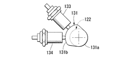
- a drive mechanism 39 of the gear shift device 41 is disposed on the upper left side of the transmission case 22 of the engine 13.
- the drive mechanism 39 is a pin gear 121 that is coaxially fixed to the left end portion of the shift drum 24 a of the change mechanism 24, a worm-shaped barrel cam 122 that engages with the pin gear 121, and the barrel cam 122 that rotates via a relay gear shaft 123.
- an electric motor 124 for applying a driving force.
- the drive mechanism 39 rotates the shift drum 24 a by driving the electric motor 124 to change the gear position of the transmission 47.
- the electric motor 124 is arranged so that its rotational drive axis C4 is along the front-rear direction.
- the drive shaft 125 of the electric motor 124 projects backward.
- a drive gear 126 is formed on the outer periphery of the tip of the drive shaft 125.
- the drive gear 126 meshes with the first relay gear 127a of the relay gear shaft 123.
- the second relay gear 127b of the relay gear shaft 123 meshes with the driven gear 128 at the front end portion of the barrel cam 122.
- the barrel cam 122 has a rotation axis C5 parallel to the axis C4 of the electric motor 124.
- a plurality of cam grooves 129 are formed on the outer periphery of the front portion of the barrel cam 122.
- the cam grooves 129 are connected to each other so as to form a single thread groove.
- a part of the plurality of pins 121 a protruding from the pin gear 121 is engaged with each cam groove 129.
- the pin gear 121 is configured by projecting the plurality of pins 121a that are equally spaced in the circumferential direction on the left side of the disk-shaped main body in parallel with the shift drum 24a.
- the rotation axis C5 of the barrel cam 122 is arranged perpendicular to the rotation axis C6 along the left-right direction of the pin gear 121 (shift drum 24a).
- the upper part of the pin gear 121 overlaps with the front part of the barrel cam 122 in a side view, and the respective pins 121a positioned at the upper part of the pin gear 121 are engaged with the respective cam grooves 129 on the outer periphery of the front part of the barrel cam 122. Note that at least one set of each cam groove 129 and each pin 121a may be engaged.
- each cam groove 129 corresponds to one row (one pitch) in the arrangement direction (front-rear direction).
- the pin gear 121 and the shift drum 24a are rotated in the shift-up direction (arrow UP direction in FIG. 11) by an angle corresponding to the one pitch.
- the rotation angle of the shift drum 24a at this time corresponds to an angle for shifting up the shift stage of the transmission 47 by one speed.
- each cam groove 129 is displaced forward by that one pitch, and the pin gear 121 and the shift drum 24a are moved. It is rotated in the downshift direction (arrow DN direction in FIG. 11) by an angle corresponding to the one pitch.
- the rotation angle of the shift drum 24a at this time corresponds to an angle for shifting down the shift stage of the transmission 47 by one speed.
- the transmission 47 is the current shift position (the shift position where power is actually transmitted via the twin clutch 26) and the side shifted up or down by one step with respect to this shift position.
- the shift positions shift positions at which power transmission is interrupted via the twin clutch 26
- that is, at the shift positions of even and odd stages are, at the shift positions of even and odd stages.
- each cam groove 129 has a holding range 129a that keeps the position in the barrel cam shaft direction (alignment direction of the cam grooves 129) constant, and a change range that gradually changes the position in the barrel cam shaft direction. 129b.
- each pin 121a is engaged in the holding range 129a of each cam groove 129, even if the barrel cam 122 rotates, the pin gear 121 and the shift drum 24a do not rotate, and each pin 121a enters the change range 129b of the cam groove 129. Is engaged, the pin gear 121 and the shift drum 24a rotate in the shift-up or shift-down direction according to the rotation of the barrel cam 122.
- each cam groove 129 is smoothly connected via the curved portion 129c.
- the curved portion 129c of each cam groove 129 is arranged in an arc shape along the circumferential direction of the pin gear 121 (alignment direction of the pins 121a).
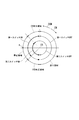
- two switch cams 131 arranged in the front-rear direction are provided on the outer periphery of the rear portion of the barrel cam 122. Further, on the left side of each switch cam 131, for example, a first or second switch 133, 134 is provided as the sensor S1 with the switch piece facing the cam surface.
- Each switch cam 131 has substantially the same shape as viewed in the barrel cam axial direction, and forms a cam surface on its outer periphery.
- the cam surface of each switch cam 131 includes a barrel cam 122, a coaxial cylindrical reference surface 131a, and a cylindrical lift surface 131b having a diameter larger than that of the reference surface 131a.
- the switch cams 131 are arranged so that the lift surface forming range has a predetermined phase difference in the barrel cam rotation direction. Specifically, as shown in FIGS. 12A and 12B, the switch cam 131 for the second switch 134 is at a predetermined angle in the CCW direction with respect to the switch cam 131 for the first switch 133. It is arranged with a phase shift of only.
- Each switch 133, 134 has its switch piece opposed to the reference surface 131 a of each switch cam 131 (when each switch 133, 134 is turned OFF) and the switch piece opposed to the lift surface 131 b of each switch cam 131. In this case (when the switches 133 and 134 are turned on), the switch piece is moved forward and backward to detect the rotation state of the barrel cam 122.
- the switches 133 and 134 are arranged so as to have the same phase in the barrel cam rotation direction.
- FIG. 14 is a diagram showing ON and OFF of the switches 133 and 134 with respect to the rotation angle of the barrel cam 122.
- each pin 121a of the pin gear 121 is each of the barrel cam 122.
- This is a stop region that is within the holding range 129a of the cam groove 129 and in which the drive torque of the electric motor 124 is zero (see FIG. 15).
- the transmission 47 so as to complete the speed change operation, even if the rotational position of the barrel cam 122 is slightly deviated, the shift position is not affected, and the shift is performed even if the drive torque of the electric motor 124 is set to zero.
- the rotation of the drum 24a is restricted and held at a predetermined shift position.
- the angle of the stop region is set to be equal to or larger than the angle at which the barrel cam 122 rotates due to inertia when the driving torque of the electric motor 124 is zero.
- each pin 121a of the pin gear 121 is within the change range 129b of each cam groove 129 of the barrel cam 122.
- a feed region in which the electric motor 124 is driven with normal torque (maximum torque ⁇ Tmax set by the system) (see FIG. 15).
- the transmission 47 is in the middle of the shifting operation, and the shift drum 24a rotates in the shift-up or shift-down direction according to the rotation of the barrel cam 122.
- the angle of the feed area corresponds to the formation angle of the change range 129b of each cam groove 129 in the barrel cam 122.
- each pin 121a of the pin gear 121 is formed in each cam groove 129 of the barrel cam 122.
- This is a CW or CCW correction region that is near the end of the holding range 129a and that drives the electric motor 124 with a small torque (minimum torque ⁇ Tmin that overcomes system friction) (see FIG. 15).
- the electric motor 124 is set to the minimum reverse torque ( ⁇ to rotate the barrel cam 122 in the CCW direction with a low torque. (Tmin) to correct the stop area.
- Tmin the minimum reverse torque
- the electric motor 124 is rotated with the minimum forward rotation torque (+ Tmin) so as to rotate the barrel cam 122 in the CW direction with a low torque. The drive is corrected so as to be the stop region.
- the switches 133 and 134 are not limited to mechanical contact types, but may be those using electricity or magnetic force or non-contact types.
- FIG. 17 is a graph showing changes in the rotation angle and rotation angular velocity of the shift drum 24a with respect to the rotation angle of the barrel cam 122.
- the cam grooves 129 are curved portions.
- the change in the rotation angle of the shift drum 24a becomes smoother, and the shift drum 24a The rising of the rotational angular velocity before and after the change range 129b becomes smooth.
- the inertia torque of the shift drum 24a at the time of up-shifting and down-shifting is suppressed, and the load on each mechanism component is suppressed. Further, after the barrel cam 122 makes one rotation, the rotation position becomes the initial position in the shift position on the side shifted up or down by one step, and it is possible to continuously perform a shifting operation from this state.
- the clutch device in the above embodiment displaces the pressure plates 52a and 52b in the axial direction by the externally supplied hydraulic pressure, and applies pressure to the clutch disks 66a and 66b supported by the clutch centers 57a and 57b.
- Hydraulic first and second disk clutches 51 a and 51 b that exhibit a predetermined engagement force are provided, and are used in the twin clutch transmission 23 of the engine 13.
- the clutch device includes connection-side hydraulic chambers 54a and 54b that apply a pressing force to the clutch connection side to the pressure plates 52a and 52b, and a pressing force to the clutch disengagement side that is applied to the pressure plates 52a and 52b. And cutting-side hydraulic chambers 55a and 55b for compensating the pressure of the return operation.
- the clutch centers 57a and 57b have flange portions 64a and 64b extending in the clutch radial direction, and the cutting-side hydraulic chambers 55a and 55b are disposed between the flange portions 64a and 64b and the pressure plates 52a and 52b. It is formed. Oil passages 68a and 68b are formed in the flange portions 64a and 64b to guide hydraulic oil in the cutting-side hydraulic chambers 55a and 55b to the outside of the hydraulic chamber. The oil passages 68a and 68b open into the cutting-side hydraulic chambers 55a and 55b at the radial intermediate portions of the flange portions 64a and 64b.
- the pressure plates 52a and 52b are disposed in the oil reservoirs radially outside the openings K of the oil passages 68a and 68b in the cutting-side hydraulic chambers 55a and 55b. It is possible to generate a hydraulic pressure that urges the clutch to be disengaged.
- the hydraulic pressure that urges the pressure plates 52a and 52b generated in the connection-side hydraulic chambers 54a and 54b to the clutch connection side is canceled out, and the influence of centrifugal force on the clutch hydraulic oil (engine oil) during clutch rotation is eliminated.
- the operating state can be kept good.
- part of the hydraulic oil in the cutting side hydraulic chambers 55a and 55b can be guided out of the hydraulic chamber through the oil passages 68a and 68b.
- This hydraulic oil can be effectively used for lubrication of other parts (clutch disks 66a, 66b, etc.).
- a separate partition or the like for forming the oil passages 68a and 68b it is possible to suppress an increase in the number of parts, volume and weight of each of the disk clutches 51a and 51b.
- the oil passages 68a and 68b extend in the flange portions 64a and 64b to the disk support portions 65a and 65b on the outer periphery of the clutch centers 57a and 57b.
- the disk clutches 51a and 51b are coaxially arranged adjacent to each other to form a twin clutch 26, and the oil passages 68a and 68b are provided in the disk clutches 51a and 51b, respectively.
- each of the disk clutches 51a and 51b in the twin clutch 26 can be reduced in size and weight, and this clutch device can be suitably used for an engine transmission of a small vehicle such as a motorcycle.
- the present invention is not limited to the above-described embodiments, and can be applied to various types of internal combustion engines such as a single cylinder engine, a V-type engine, and a vertically placed engine having a crank axis line in the front-rear direction. Further, the present invention is not limited to a motorcycle, and may be applied to a three-wheel or four-wheel saddle-ride type vehicle, or a scooter type vehicle having a low floor footrest. And the structure in the said Example is an example of this invention, and various changes are possible in the range which does not deviate from the summary of this invention as well as being applicable to a four-wheeled passenger car.
- the hydraulic pressure that biases the pressing member toward the clutch disengagement side in the oil reservoir radially outside the opening of the oil passage in the pressure compensation hydraulic chamber. Can be generated. Further, it is possible to cancel the hydraulic pressure that urges the pressing member generated in the connection-side hydraulic chamber to the clutch connection side. Thereby, the influence of the centrifugal force on the clutch operating oil at the time of clutch rotation can be eliminated and the clutch operating state can be kept good.
- a part of the hydraulic oil in the pressure compensation hydraulic chamber can be led out of the hydraulic chamber through the oil passage, and the hydraulic oil can be effectively used for lubrication of other parts.
- an increase in the number of parts, volume and weight of the disk clutch can be suppressed.
Abstract
La présente invention concerne un dispositif d'embrayage utilisé dans une transmission d'un moteur et doté d'un premier embrayage à disque hydraulique. Le premier embrayage à disque comprend un centre d'embrayage possédant une bride s'étendant dans la direction radiale de l'embrayage, un disque d'embrayage soutenu par le centre d'embrayage, un élément de pression pouvant être déplacé axialement par la pression hydraulique fournie à partir de l'extérieur et appuyant sur le disque d'embrayage, une chambre de pression hydraulique côté connexion destinée à appliquer une force de pression orientée du côté de la mise en prise de l'embrayage sur l'élément de pression et une chambre de pression hydraulique de compensation de pression destinée à appliquer une force de pression orientée vers le côté de libération de l'embrayage et de l'élément de pression et compensant la pression pour permettre le retour de l'élément de pression. La chambre de pression hydraulique de compensation de pression est formée entre la bride et l'élément de pression. Une conduite d'huile est formée dans la bride, pour amener l'huile hydraulique dans la chambre de pression hydraulique de compensation de pression à l'extérieur de la chambre. La conduite d'huile est ouverte dans une section radialement intermédiaire de la bride à l'intérieur de la chambre de pression hydraulique de compensation de pression.
Applications Claiming Priority (2)
| Application Number | Priority Date | Filing Date | Title |
|---|---|---|---|
| JP2008021891A JP2009180350A (ja) | 2008-01-31 | 2008-01-31 | クラッチ装置 |
| JP2008-021891 | 2008-01-31 |
Publications (1)
| Publication Number | Publication Date |
|---|---|
| WO2009096362A1 true WO2009096362A1 (fr) | 2009-08-06 |
Family
ID=40912715
Family Applications (1)
| Application Number | Title | Priority Date | Filing Date |
|---|---|---|---|
| PCT/JP2009/051203 WO2009096362A1 (fr) | 2008-01-31 | 2009-01-26 | Dispositif d'embrayage |
Country Status (2)
| Country | Link |
|---|---|
| JP (1) | JP2009180350A (fr) |
| WO (1) | WO2009096362A1 (fr) |
Families Citing this family (8)
| Publication number | Priority date | Publication date | Assignee | Title |
|---|---|---|---|---|
| JP5372792B2 (ja) * | 2010-01-25 | 2013-12-18 | 本田技研工業株式会社 | 油圧クラッチの作動回路 |
| JP5461314B2 (ja) * | 2010-06-08 | 2014-04-02 | 本田技研工業株式会社 | クラッチ装置 |
| JP5911782B2 (ja) * | 2012-09-28 | 2016-04-27 | 本田技研工業株式会社 | 鞍乗り型車両の変速装置 |
| CN104781590B (zh) * | 2012-11-19 | 2017-05-10 | 爱信艾达株式会社 | 自动变速器 |
| JP6392606B2 (ja) * | 2014-09-25 | 2018-09-19 | 本田技研工業株式会社 | 内燃機関用オイルポンプ |
| JP2015108453A (ja) * | 2015-02-13 | 2015-06-11 | ヤマハ発動機株式会社 | 変速装置 |
| JP6818648B2 (ja) * | 2017-07-13 | 2021-01-20 | 本田技研工業株式会社 | 動力伝達装置 |
| US11655861B2 (en) | 2020-09-25 | 2023-05-23 | T.P.P. Co. | Friction clutch pressure plate device |
Citations (3)
| Publication number | Priority date | Publication date | Assignee | Title |
|---|---|---|---|---|
| JPS5557728A (en) * | 1978-10-20 | 1980-04-28 | Mitsubishi Heavy Ind Ltd | Rotary clutch of power transmitting device |
| JP2006298272A (ja) * | 2005-04-22 | 2006-11-02 | Exedy Corp | トルク伝達装置 |
| JP2007177905A (ja) * | 2005-12-28 | 2007-07-12 | Honda Motor Co Ltd | ツインクラッチ装置 |
-
2008
- 2008-01-31 JP JP2008021891A patent/JP2009180350A/ja active Pending
-
2009
- 2009-01-26 WO PCT/JP2009/051203 patent/WO2009096362A1/fr active Application Filing
Patent Citations (3)
| Publication number | Priority date | Publication date | Assignee | Title |
|---|---|---|---|---|
| JPS5557728A (en) * | 1978-10-20 | 1980-04-28 | Mitsubishi Heavy Ind Ltd | Rotary clutch of power transmitting device |
| JP2006298272A (ja) * | 2005-04-22 | 2006-11-02 | Exedy Corp | トルク伝達装置 |
| JP2007177905A (ja) * | 2005-12-28 | 2007-07-12 | Honda Motor Co Ltd | ツインクラッチ装置 |
Also Published As
| Publication number | Publication date |
|---|---|
| JP2009180350A (ja) | 2009-08-13 |
Similar Documents
| Publication | Publication Date | Title |
|---|---|---|
| JP4704308B2 (ja) | ツインクラッチ式変速機 | |
| JP4699326B2 (ja) | ツインクラッチ装置 | |
| JP4791314B2 (ja) | ギヤシフト装置 | |
| JP4754453B2 (ja) | ツインクラッチ装置 | |
| JP4800167B2 (ja) | ギヤシフト装置 | |
| US8057359B2 (en) | Twin clutch type speed change control system | |
| US8166840B2 (en) | Twin clutch type speed change control system | |
| WO2009096362A1 (fr) | Dispositif d'embrayage | |
| JP4696105B2 (ja) | 自動二輪車のクラッチ制御装置 | |
| JP5165223B2 (ja) | 自動二輪車 | |
| US8371987B2 (en) | Automatic speed change control system for vehicle | |
| US8235868B2 (en) | Clutch control apparatus for vehicle |
Legal Events
| Date | Code | Title | Description |
|---|---|---|---|
| 121 | Ep: the epo has been informed by wipo that ep was designated in this application |
Ref document number: 09706290 Country of ref document: EP Kind code of ref document: A1 |
|
| DPE2 | Request for preliminary examination filed before expiration of 19th month from priority date (pct application filed from 20040101) | ||
| NENP | Non-entry into the national phase |
Ref country code: DE |
|
| 122 | Ep: pct application non-entry in european phase |
Ref document number: 09706290 Country of ref document: EP Kind code of ref document: A1 |