EP2063094B1 - Composant coulé pour un moteur à combustion interne - Google Patents
Composant coulé pour un moteur à combustion interne Download PDFInfo
- Publication number
- EP2063094B1 EP2063094B1 EP09001655.1A EP09001655A EP2063094B1 EP 2063094 B1 EP2063094 B1 EP 2063094B1 EP 09001655 A EP09001655 A EP 09001655A EP 2063094 B1 EP2063094 B1 EP 2063094B1
- Authority
- EP
- European Patent Office
- Prior art keywords
- cast
- fuel
- cylinder
- cylinder crankcase
- supply line
- Prior art date
- Legal status (The legal status is an assumption and is not a legal conclusion. Google has not performed a legal analysis and makes no representation as to the accuracy of the status listed.)
- Expired - Lifetime
Links
- 238000002485 combustion reaction Methods 0.000 title claims abstract description 15
- 239000012530 fluid Substances 0.000 claims abstract description 15
- 239000000446 fuel Substances 0.000 claims description 46
- 238000001816 cooling Methods 0.000 claims description 22
- 239000000463 material Substances 0.000 claims description 13
- 239000000314 lubricant Substances 0.000 claims description 11
- 239000007921 spray Substances 0.000 claims description 5
- 238000005266 casting Methods 0.000 description 40
- 238000000034 method Methods 0.000 description 11
- 238000005553 drilling Methods 0.000 description 9
- 238000004519 manufacturing process Methods 0.000 description 9
- 238000000465 moulding Methods 0.000 description 4
- 239000002131 composite material Substances 0.000 description 3
- 238000005461 lubrication Methods 0.000 description 3
- 239000007769 metal material Substances 0.000 description 3
- 238000012805 post-processing Methods 0.000 description 3
- XLYOFNOQVPJJNP-UHFFFAOYSA-N water Substances O XLYOFNOQVPJJNP-UHFFFAOYSA-N 0.000 description 3
- 230000015572 biosynthetic process Effects 0.000 description 2
- 238000010276 construction Methods 0.000 description 2
- 238000011161 development Methods 0.000 description 2
- 238000002347 injection Methods 0.000 description 2
- 239000007924 injection Substances 0.000 description 2
- 239000007788 liquid Substances 0.000 description 2
- 239000002184 metal Substances 0.000 description 2
- 229910052751 metal Inorganic materials 0.000 description 2
- 238000012545 processing Methods 0.000 description 2
- 239000013585 weight reducing agent Substances 0.000 description 2
- 229910001018 Cast iron Inorganic materials 0.000 description 1
- 229910000831 Steel Inorganic materials 0.000 description 1
- 230000006978 adaptation Effects 0.000 description 1
- 230000003749 cleanliness Effects 0.000 description 1
- 238000009749 continuous casting Methods 0.000 description 1
- 238000005520 cutting process Methods 0.000 description 1
- 230000006378 damage Effects 0.000 description 1
- 238000013461 design Methods 0.000 description 1
- 238000004512 die casting Methods 0.000 description 1
- -1 ferrous metals Chemical class 0.000 description 1
- 239000006260 foam Substances 0.000 description 1
- 238000003384 imaging method Methods 0.000 description 1
- 238000001746 injection moulding Methods 0.000 description 1
- 238000010114 lost-foam casting Methods 0.000 description 1
- 238000003754 machining Methods 0.000 description 1
- 150000002739 metals Chemical class 0.000 description 1
- 239000011347 resin Substances 0.000 description 1
- 229920005989 resin Polymers 0.000 description 1
- 239000007787 solid Substances 0.000 description 1
- 239000010959 steel Substances 0.000 description 1
- 238000012549 training Methods 0.000 description 1
- 238000012546 transfer Methods 0.000 description 1
Images

Classifications
-
- B—PERFORMING OPERATIONS; TRANSPORTING
- B22—CASTING; POWDER METALLURGY
- B22D—CASTING OF METALS; CASTING OF OTHER SUBSTANCES BY THE SAME PROCESSES OR DEVICES
- B22D19/00—Casting in, on, or around objects which form part of the product
- B22D19/0009—Cylinders, pistons
-
- B—PERFORMING OPERATIONS; TRANSPORTING
- B22—CASTING; POWDER METALLURGY
- B22D—CASTING OF METALS; CASTING OF OTHER SUBSTANCES BY THE SAME PROCESSES OR DEVICES
- B22D19/00—Casting in, on, or around objects which form part of the product
- B22D19/0072—Casting in, on, or around objects which form part of the product for making objects with integrated channels
-
- F—MECHANICAL ENGINEERING; LIGHTING; HEATING; WEAPONS; BLASTING
- F01—MACHINES OR ENGINES IN GENERAL; ENGINE PLANTS IN GENERAL; STEAM ENGINES
- F01M—LUBRICATING OF MACHINES OR ENGINES IN GENERAL; LUBRICATING INTERNAL COMBUSTION ENGINES; CRANKCASE VENTILATING
- F01M11/00—Component parts, details or accessories, not provided for in, or of interest apart from, groups F01M1/00 - F01M9/00
- F01M11/02—Arrangements of lubricant conduits
-
- F—MECHANICAL ENGINEERING; LIGHTING; HEATING; WEAPONS; BLASTING
- F02—COMBUSTION ENGINES; HOT-GAS OR COMBUSTION-PRODUCT ENGINE PLANTS
- F02F—CYLINDERS, PISTONS OR CASINGS, FOR COMBUSTION ENGINES; ARRANGEMENTS OF SEALINGS IN COMBUSTION ENGINES
- F02F7/00—Casings, e.g. crankcases or frames
- F02F7/0043—Arrangements of mechanical drive elements
- F02F7/0053—Crankshaft bearings fitted in the crankcase
-
- F—MECHANICAL ENGINEERING; LIGHTING; HEATING; WEAPONS; BLASTING
- F01—MACHINES OR ENGINES IN GENERAL; ENGINE PLANTS IN GENERAL; STEAM ENGINES
- F01M—LUBRICATING OF MACHINES OR ENGINES IN GENERAL; LUBRICATING INTERNAL COMBUSTION ENGINES; CRANKCASE VENTILATING
- F01M11/00—Component parts, details or accessories, not provided for in, or of interest apart from, groups F01M1/00 - F01M9/00
- F01M11/02—Arrangements of lubricant conduits
- F01M2011/026—Arrangements of lubricant conduits for lubricating crankshaft bearings
Definitions
- the invention relates to a cast component for an internal combustion engine, wherein the component is a cylinder crankcase having at least one guide channel, which is formed in the form of a tube and molded during casting of the component and which forwards a fluid medium to a demand site wherein the fluid medium is oil.
- Internal combustion engines in the form of internal combustion engines, are an integral part of vehicles (for example cars and commercial vehicles, ships, etc.) and are also used as stationary engines.
- internal combustion engines include numerous molded components having at least one guide channel (also called a supply line) which relays a fluid medium (e.g., oil, water gas, or other liquid or gaseous media) to a demand site in the engine or adjacent areas.
- a fluid medium e.g., oil, water gas, or other liquid or gaseous media
- Some of the guide channels can also be used to cool a component itself. Where needed are the locations where the particular medium is needed, e.g. bearings to be lubricated, areas to be cooled, etc.
- a guide channel or a plurality of guide channels comes / come especially in a cylinder crankcase or adjacent thereto add-on parts.
- Guide channels are introduced in a known manner by mechanical processing on machine tools or transfer lines, ie drilled. These are done in several elaborate, high-precision work steps Central main ducts and sidetracking channels, which make junctions to individual needs sites, are drilled into the component. Subsequently, numerous, unnecessary accesses must be closed permanently and safely. Very long, linear guide channels, such as those of the main oil passage in a cylinder crankcase are today even occasionally poured by pouring a pipe or by saving by a corresponding casting core.
- the JP 59 079019 A discloses a cylinder crankcase with a main oil channel cast in as a tube.
- the tube extends over the housing length, is mostly exposed and is stored in the casting material of the bulkheads.
- Starting from the crankshaft bearings run in the bulkheads holes to the cast-in tube, which are subsequently introduced mechanically into the cylinder crankcase.
- lubricant flows from the main oil passage through the bores to the crankshaft bearings.
- a cylinder crankcase miL is described with an oil supply for the piston cooling, which includes numerous holes, which are subsequently introduced mechanically into the casting.
- the main oil channel is realized as a bore and runs in a housing wall.
- numerous oblique holes are provided in the housing, which have also been subsequently introduced mechanically into the casting. They each terminate with their one end in a cylinder space and with their other end disposed in the region of the crankshaft bearings in a drilled lubricant supply passage connected to the main oil passage.
- lubricant that has not been taken up in the crankshaft bearings, passes out of the bearing area via the oblique holes in the cylinder chambers to lubricate the cylinder walls and to cool the piston.
- the invention is based on the object in a component - namely a cylinder crankcase - the above-mentioned type to reduce manufacturing and cost.
- the cast component is a cylinder crankcase.
- a cylinder crankcase has numerous guide channels, especially for oil and water, so that by pouring a guide channel or more guide channels, which is or in each case designed as a tube, a considerable saving in manufacturing effort is achieved.
- this is not the main oil channel, since this belongs to the state of the art.
- Object of the invention it is rather, (possibly next to the pouring of the main oil passage as a pipe) to pour another guide channel or more other channels for oil or other media to need as a pipe (e).
- At least one guide channel can be cast as a pipe in the cylinder crankcase, which forms a fuel line.
- a cast-pipe guide channel or more cast-pipe guide channels offers a high degree of cleanliness on the inner channel wall and the cavity unlike the prior art free from residues due to mechanical introduction of the channel or free of casting residues (eg core residues) due to a pouring of the channel into the component as a cavity by inserting is a kernel.
- This aspect is particularly important in a guide channel for bearing lubrication, as in the channel possibly remaining residues with the oil during engine operation in the camp and would lead to the destruction of the bearing.
- At least one guide channel is cast as a tube, which forms an oil supply line for the supply of the piston cooling or lubrication of the cylinder wall.
- the at least one cast-in as a duct guide channel is arranged such that it extends partially or completely exposed, in some cases, ie it can extend outside of the component on the outside or inside. Locally the On the other hand, the guide channel must be looped around with casting material of the component in order to ensure a firm bond between the channel and the component.
- the guide channel may be completely exposed (based on its longitudinal extent) or may be partly cast in the component wall. The measure of the partially exposed course offers over the prior art in which the drilled or cast with cores guide channels can extend only in the wall of the component, the advantage that the wall thickness of the component can be significantly reduced and thereby saved on material and weight ,
- a plurality of pistons or cylinders are supplied by a common oil supply from.
- the oil supply can be suitably designed and arranged such that it extends in the longitudinal extension of the cylinder crankcase and branch off several spray nozzles, the oil directed each injected into a cylinder space below a piston head, thereby cooling the piston crown on the one hand and lubricated on the other the respective cylinder wall becomes.
- a plurality of oil supply lines it is also possible for a plurality of oil supply lines to be cast into a cylinder or to a plurality of cylinders, possibly with other progressions.
- the component comprises a plurality of cast guide channels in order to save manufacturing and cost.
- the guide channels can be introduced in each case as a single connecting tube for the medium guide. This means that when pouring several individual, correspondingly shaped tubes are cast as connecting parts with. This provides a high degree of freedom in terms of the course of the guide channels.
- the cast-in guide channels are realized by a branched pipe system. For this purpose, several pipes to a pipe system are connected to each other (eg welded) before pouring and then the pipe assembly has been cast with. A combination of guide channels in pipe composite form and individual connecting parts on the same component is possible and advantageous.
- the cylinder crankcase at least one cast-in as a tube guide channel, which forms a fuel line for the supply of a fuel pump.
- the fuel line advantageously extends in the longitudinal extension of the cylinder crankcase in the region of a housing outer wall.
- a plurality of fuel lines are cast as tubes, e.g. at least one supply line and at least one return line.
- the at least one cast-in guide channel has different cross-sectional shapes in its course.
- a good adaptation to the respective construction of the component is achieved.
- narrow contour areas can be overcome.
- the respective cross-sectional shapes to be realized depend on the particular construction of the component. Different cross-sectional shapes on a tube can be removed prior to pouring e.g. realize by hydroforming of the tube.
- the component is made of a metallic material or plastic.
- the at least one cast guide channel made of a metallic material or plastic.
- metallic materials such as steel, all cast iron materials, light metals, non-ferrous metals come into question. Which material is to be preferably used in particular also depends, inter alia, on the particular component to be cast.
- trained and arranged cast-in tubes can be realized as a guide channels in an attachment of a cylinder crankcase - in particular in a cylinder head, a gear housing, a gear housing, an oil pan or the like.
- guide channels in the cylinder crankcase or in the / the attachment (s) can be supplied by a common or multiple supply circuits.
- a method for producing a cast component for an internal combustion engine wherein the component is a cylinder crankcase having at least one guide channel which forwards a fluid medium to a demand site, provides that a tube is used to form the at least one guide channel is incorporated with the desired course in a mold required for casting or introduced into a casting core or incorporated into a lost model or in the molding medium cavity filling and then the component is poured with the casting method to be used in each case.
- the tube can also be incorporated in several casting cores, which can be mounted as individual cores to form a core block.
- the einzug manende pipe is installed in the mold (possibly by means of supports) or introduced into the casting core (eg injected into a sand core or in the Core manufacturing incorporated with) or incorporated into a lost model or directly embedded in the loose mold medium cavity filling, or the tube is mounted at a pipe end in the casting core.
- a cast component according to the invention can be manufactured with different casting methods.
- the component is cast in a casting process with lost shape, for example in a pure core molding process, a Kernform- iVm green mold process, Kernform- iVm cold resin molding process, etc.
- the component in a Continuous casting process, eg mold casting, die casting, injection molding, etc.
- the component is cast in the lost foam process.
- Advantages of the Lost Foam casting process are, for example, the lack of core residues on the cast component, the high surface quality, high-quality contour definition and great imaging accuracy, and thus a relatively low reworking effort.
- the tubes required for this purpose can preferably be introduced as individual connecting tubes. It may also be advantageous to connect a plurality of tubes to a corresponding pipe system, to position the prefabricated pipe system in the casting mold, core, etc., and then to pour it with. Furthermore, it may be advantageous in some variants to connect a plurality of tubes in each case to a partial tube system and to pour several partial tube systems into the component. Which variant is preferable depends on the specific task.
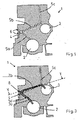
- a crankshaft bearing 2 and a camshaft bearing 3 and a main oil passage 4 are shown in cross section. Furthermore, longitudinally cut guide channels 5a, 5b can be seen which run from the main oil channel 4 to the crankshaft bearing 2 or camshaft bearing 3 and provide during engine operation for the lubrication of camshaft and crankshaft bearings.
- the outgoing from the camshaft bearing 3 guide channel 5c leads to an attachment of the cylinder crankcase 1, in this case to a cylinder head, not shown.
- the illustrated guide channels 5a, 5b, 5c are subsequently introduced into the cast cylinder crankcase 1, ie drilled. Therefore, only a straight course of the guide channels 5 is possible, and the housing 1 has manufacturing-related access 6 to the outside (to recognize left), which are to be closed later.
- Fig. 2 is the main oil channel 4 off Fig. 1 cut longitudinally, and there are several of them branching guide channels 5b, which lead to bearings 3 for the camshaft to recognize. Furthermore, recesses 22 in the contour region of the cylinder crankcase 1 shown. Corresponding recesses 22 are also in the Fig. 4 and 6 to recognize.
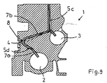
- Fig. 3 shows a cast component for an internal combustion engine having at least one guide channel 5, which forwards a fluid medium to a demand site. And it is a cylinder crankcase 1. The cutting position corresponds to that of Fig. 1 ,
- a guide channel 5d which has been formed in the form of a tube and poured in during casting of the cylinder crankcase 1 with.
- the single connecting tube 7, which is cast in as a guide channel 5d, is bent here in a "handle-like manner".
- a guide channel 5 d also have a different shape or a different course than shown.
- a section 7a extends to a crankshaft bearing 2 and another section 7b to a camshaft bearing 3.
- the bend 8 is located at the point where the main oil channel 4, which in this embodiment is drilled in a conventional manner is subsequently introduced, will run.
- crankshaft bearings can be supplied with oil via a tube guide channel or a plurality of tube guide channels, and the camshaft bearings can be supplied by mechanically introduced channels in the conventional way.
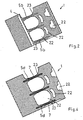
- the main oil passage 4 and the guide channels 5 are formed to the camshaft bearings 3 and crankshaft bearings 2 as cast-in tubes, and this is realized by a branched, cast-pipe system 9.
- pipes with the appropriate dimensions length, diameter, cross-sectional shape, etc. have been connected before casting to a pipe system 9, which has subsequently been poured in a suitable casting process.
- the cast-in as tubes guide channels 5 is not completely of casting material be surrounded, ie run in the component, must, but can also be partially exposed. Furthermore, the guide channels 5 may also have a curved, adapted to the contour course course.
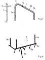
- Fig. 7 shows a connecting tube 7 for a "suitcase handle" guide channel 5d in different views.
- the to be recognized core supports 10 serve the lateral support during the casting process. However, it is also possible to do without core supports 10, for example, if the ends of the connecting tube 7 are anchored sufficiently firmly in casting cores.
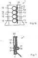
- Fig. 8 shows an example of a pipe system 9. From a main guide channel 9a branch off several secondary ducts 9b, which lead to the individual needs and supply them with the appropriate medium.
- crankcase 1 are - according to the first example of the Fig. 3 and 4 -
- Several individual, "suitcase-like" connecting pipes 7 have been poured as a guide channels 5d during casting of the housing.
- the sections 7a, 7b while the crankshaft bearing 2 and the camshaft bearing 3 are supplied from the subsequently introduced by drilling main oil passage 4, which intersects the connecting pipes 7, respectively, with lubricant.
- the guide channels 5c to the cylinder heads are not subsequently bored in the cylinder crankcase 1, but also realized in the form of casting the housing with cast-in pipes, whereby advantageously an additional post-processing step is saved on the casting.
- a connecting pipe 7 and a pipe for the formation of the guide channel 5c have been connected to each other before pouring.
- a guide channel 5c to the cylinder head also branch off from a connecting pipe 7 at a location other than shown. It is also possible that a guide channel 5c is not fed via a connecting pipe 7 with lubricant, but directly from the drilled main oil passage 4 (eg, by pouring into the formation of guide channels 5c for supplying the cylinder heads separate, correspondingly positioned pipes). Furthermore, the leading to the cylinder heads, designed as a cast-in tubes guide channels 5c part of a cast-pipe system (corresponding to that in the FIGS. 5 and 6 Example shown) and branch off either directly from the tubular main oil passage 4 or sub-guide channels 9b.
- a tubular guide channel 5c not branch off from the main oil passage 4, a connecting pipe 7, a secondary guide channel 9b, etc., but in the area of a bearing (here, for example, the camshaft bearing 3, but other bearings are possible) in a groove of a bearing ring and from There are lubricants supplied.
- Fig. 10 shows a cylinder crankcase 1 according to the invention as a cast component for an internal combustion engine. Laterally visible oil sump connection surfaces 14 to which an oil sump is fastened.
- the cylinder crankcase 1 has at least one guide channel 5e, which forwards a fluid medium to a point of need, is formed in the form of a pipe and is cast in during the casting of the cylinder crankcase 1.
- the guide channel 5e cast in as a tube forms an oil feed line 11 for the piston cooling, ie it conducts oil as a fluid medium to a point of need.
- the oil supply line 11 ends here via a recess 21 on an end face 15 of the cylinder crankcase 1 and is from an oil pump supplied with oil.
- lubricant could be fed into the oil supply line 11 at another point of the oil circuit within the cylinder crankcase 1.
- the cast-in pipe guide channel 5e is arranged in the longitudinal extension of the cylinder crankcase 1, ie transversely to the cylinders 12. He runs here in the area of the crank chambers at the lower cylinder areas at a certain distance from the Zylinderau Consujar. It can be seen that the guide channel 5e is adapted to the shape of the cylinder 12, so that there is a "wave-like" curved course.
- the oil supply line 11 is formed in the embodiment substantially exposed. In several places it is locally looped with casting material of the component. These Gußhalterept 13 cause a solid composite of oil supply 11 and component.
- the Gußhalterept 13 here form the mounting points for the spray nozzles, not shown.
- the spray nozzles are subsequently introduced mechanically into the oil feed line 11 and in each case designed and arranged such that they inject lubricant directed into a cylinder space under a piston crown. This cools the pistons and lubricates the cylinder walls.
- oil supply line 11 could also have a different course or another arrangement.
- several guide channels 5e which form oil supply lines 11 for the piston cooling, could also be cast. If necessary, the oil supply line 11 could also advantageously have different cross-sectional shapes in their course.
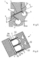
- Fig. 11 shows a cylinder crankcase 1 as a cast component for an internal combustion engine, which has at least one guide channel 5f, which forwards a fluid medium to a demand site, formed in the form of a tube and cast in the casting of the cylinder crankcase 1 with.
- the guide channel 5f cast in as a tube forms a pressure oil line 16 to a cylinder head.
- the cast as a pipe pressure oil line 16 is supplied directly here by a main oil passage 4 with lubricant.
- the connection of the guide channel 5f is made to the oil circuit in the cylinder crankcase 1 shown.
- the pressure oil line 16 could be fed from another area of the oil balance within the cylinder crankcase 1 by, for example, before being poured into the cylinder crankcase with another oil-carrying line has been connected to a composite pipe (see. Fig. 9 ) or by opening into a groove of a bearing. Numerous other advantageous variants are possible.
- a threaded bore 18 and another recess 19 - has the cast as a tube guide channel 5f adapted to the contour course course and here "curved" bent.
- the pressure oil line 16 is completely surrounded here in longitudinal extension with casting material.
- it could, depending on the design conditions, advantageously also be arranged such that it runs partially or completely exposed in parts.
- it could advantageously have different cross-sectional shapes in its course, e.g. To overcome bottlenecks in the cylinder crankcase 1.
- the appropriate number of cast as a pipe pressure oil lines 16 for the oil supply of the cylinder head and the cylinder heads on the cylinder crankcase 1 depends on the respective assembly of the engine.
- the Fig. 12a and 12b show yet another advantageous cylinder crankcase 1 as a cast component for an internal combustion engine, which has at least one guide channel 5g, which forwards a fluid medium to a demand site, formed in the form of a tube and is molded during casting of the cylinder crankcase 1 with.
- This cast in as a pipe Guide channel 5g forms a fuel line 24 for the supply of a fuel pump with fuel as a fluid medium. Due to the curved line 25 is in Fig. 12a indicated that the representation of the cast-in fuel line 24 is located in a different sectional plane than the rest of the drawing.
- guide channels 5g are each cast as a tube in an outer wall 26 of the cylinder crankcase 1, and that they extend in the longitudinal extension of the cylinder crankcase 1 (vg1. Fig. 12b ).
- the middle fuel line 24 is a fuel supply line and the outer fuel lines 24 are each a fuel return line.
- a recess 27 shown in the later a fuel pump is used.
- a plurality of recesses 27 are provided for fuel pumps over the length of the central fuel line 24, wherein the number depends on the number of cylinders of the respective engine.
- the fuel supply line is cut or severed in each case in the areas of the recesses 27 for the fuel pumps, thereby producing the connections between the guide channel 5g and pumps. Openings in the fuel return lines are later also mechanically introduced.
- each fuel is removed from the supply line and pumped through a connection line to an injection nozzle in a cylinder head.
- fuel lines are mechanically introduced into the outer wall of a cylinder crankcase as long, straight holes.
- the pouring of one or more fuel pipe (s) as a pipe with said manufacturing method offers the advantageous possibility that the guide channel, if necessary, can be bent. It may advantageously be exposed predominantly or in sections, may not also have round cross-sectional shapes or have different cross-sectional shapes in its course. Thereby, e.g. a reduction in the component wall thickness possible, resulting in savings in material and weight and reduced manufacturing costs.
- the course of the lines can be optimized. Since the fuel line (s) 24 are already integrated in the finished cast component, the workload is also significantly reduced overall.
- FIG. 13 An example of such an advantageous combination shows Fig. 13 , There is a cylinder crankcase 1 can be seen, in which the supply of crankshaft bearings 2 and 3 camshaft bearings with lubricant is realized by cast into the bulkheads 23 curved guide channels 5d (corresponding to that in the Fig. 3 and 4 example described).
- a cast-in as a pipe guide channel 5c is provided, which forms a pressure oil pipe 16 to a cylinder head. Unlike in the Fig. 11 shown example, this is not supplied directly from the main oil channel 4 with oil, but branches off from the cast-guide channel 5d.
- guide tubes 5g cast in as tubes are provided, which form fuel lines 24 (supply line and return lines) for the supply of a fuel pump (corresponding to the exemplary embodiment of FIG Fig. 12 ).
- a cast-in bearing supply via separate connecting pipes 7 or a cast-in pipe system 9 i.V.m. a cast supply line 11 for the piston cooling; a cast-in supply line 11 for the piston cooling i.V.m. a cast-in fuel line 24; a cast-in pressure oil line 16 to the cylinder head i.V.m. a cast-in fuel line 24, etc.
- the guide channels illustrated in the exemplary embodiments by way of example for the oil supply and the fuel supply 5 can be transferred accordingly to guide channels 5 for another medium.
- cylinder crankcase 1 wherein the cylinder crankcase may be formed in one or more parts or it may also be a crankcase with attached cylinder housing.
Claims (10)
- Pièce coulée destinée à un moteur à combustion interne, la pièce étant un carter de vilebrequin (1) comportant au moins un canal de guidage (5, 5e) conçu sous la forme d'un tuyau et coulé ensemble avec la pièce, permettant de guider un fluide vers un point de consommation, le fluide étant de l'huile,
caractérisée en ce que
l'au moins un canal de guidage (5e) coulé en tant que tuyau constitue une alimentation (11) pour le refroidissement des pistons,
l'alimentation (11) pour le refroidissement des pistons s'étend essentiellement à découvert, tout en étant enrobée localement dans le matériau de coulage de la pièce, par endroits, à la manière d'une coque, de manière à former des supports coulés (13) et
les supports coulés (13) constituent des points de montage pour des buses, qui peuvent par la suite être intégrées mécaniquement dans l'alimentation (11) pour le refroidissement des pistons, et qui sont respectivement conçues et disposées de telle façon, qu'elles injectent du lubrifiant de façon dirigée dans un espace de cylindre, sous un fond de piston. - Pièce coulée selon la revendication 1,
caractérisée en ce que
l'alimentation (11) pour le refroidissement des pistons s'étend dans la région des chambres de vilebrequin aux zones inférieures des cylindres avec une certaine distance aux parois extérieures des cylindres. - Pièce coulée selon l'une des revendications précédentes,
caractérisée en ce que
l'alimentation (11) pour le refroidissement des pistons est disposée dans le sens longitudinal du carter de vilebrequin (1) et en ce que plusieurs cylindres (12) sont alimentés en huile par une alimentation commune (11). - Pièce coulée selon l'une des revendications précédentes,
caractérisée en ce que
les supports coulés (13) sont prévus aux parois extérieures des cylindres. - Pièce coulée selon l'une des revendications précédentes,
caractérisée en ce que
le carter de vilebrequin (1) comprend au moins un canal de guidage (5g) coulé en tant que tuyau, qui forme une conduite de carburant (24) pour l'alimentation d'une pompe à carburant. - Pièce coulée selon la revendication 5,
caractérisée en ce que
la conduite de carburant (24) s'étend dans le sens longitudinal du carter de vilebrequin (1). - Pièce coulée selon la revendication 5 ou 6,
caractérisée en ce que
la conduite de carburant (24) forme une conduite d'alimentaiton en carburant, et en ce que plusieurs évidements (27) pour pompes à carburant sont prévus dans le carter de vilebrequin (1) dans la longueur de la conduite d'alimentation en carburant, dans lesquels des pompes à carburant peuvent être introduites, la conduite d'alimentation en carburant étant entaillée resp. coupée respectivement dans les régions des évidements (27), par des mesures de traitement ultérieur sur le carter de vilebrequin coulé (1), ce qui permet de réaliser les liaisons entre la canal de guidage (5g) et les pompes à carburant. - Pièce coulée selon l'une des revendications 5 à 7,
caractérisée en ce que
une conduite de carburant (24) coulée en tant que tuyau forme une conduite de retour de carburant. - Pièce coulée selon l'une des revendications précédentes,
caractérisée en ce que
au moins un canal de guidage coulé (5, 5e, 5g) est disposé de telle manière, qu'il s'étend complètement ou partiellement à découvert sur certains tronçons. - Pièce coulée selon l'une des revendications précédentes,
caractérisée en ce que
au moins un canal de guidage coulé (5, 5e, 5g) présente des sections transversales variables le long de son trajet.
Applications Claiming Priority (3)
| Application Number | Priority Date | Filing Date | Title |
|---|---|---|---|
| DE10255284 | 2002-11-26 | ||
| DE10304971A DE10304971C5 (de) | 2002-11-26 | 2003-02-06 | Gegossenes Bauteil für eine Brennkraftmaschine |
| EP03767447A EP1570167B1 (fr) | 2002-11-26 | 2003-11-25 | Composant coule destine a un moteur a combustion interne |
Related Parent Applications (1)
| Application Number | Title | Priority Date | Filing Date |
|---|---|---|---|
| EP03767447A Division EP1570167B1 (fr) | 2002-11-26 | 2003-11-25 | Composant coule destine a un moteur a combustion interne |
Publications (3)
| Publication Number | Publication Date |
|---|---|
| EP2063094A2 EP2063094A2 (fr) | 2009-05-27 |
| EP2063094A3 EP2063094A3 (fr) | 2009-12-09 |
| EP2063094B1 true EP2063094B1 (fr) | 2014-05-14 |
Family
ID=32318719
Family Applications (1)
| Application Number | Title | Priority Date | Filing Date |
|---|---|---|---|
| EP09001655.1A Expired - Lifetime EP2063094B1 (fr) | 2002-11-26 | 2003-11-25 | Composant coulé pour un moteur à combustion interne |
Country Status (4)
| Country | Link |
|---|---|
| EP (1) | EP2063094B1 (fr) |
| AT (1) | ATE423900T1 (fr) |
| DE (3) | DE10304971C5 (fr) |
| ES (2) | ES2486303T3 (fr) |
Families Citing this family (16)
| Publication number | Priority date | Publication date | Assignee | Title |
|---|---|---|---|---|
| DE10340157B4 (de) * | 2003-09-01 | 2008-10-02 | Audi Ag | Vorrichtung zur Medienführung in einem Zylinderkurbelgehäuse |
| DE102005048650B4 (de) * | 2005-10-11 | 2007-09-13 | Daimlerchrysler Ag | Fertigungsverfahren und Bauweise für Gussbauteile mit Formhohlräumen |
| JP4432879B2 (ja) | 2005-11-11 | 2010-03-17 | トヨタ自動車株式会社 | 内燃機関のオイル通路構造 |
| DE102006002628A1 (de) * | 2006-01-19 | 2007-08-02 | Zf Friedrichshafen Ag | Gehäuse |
| DE102006034341A1 (de) | 2006-07-23 | 2008-01-31 | Fritz Winter Eisengiesserei Gmbh & Co. Kg | Verfahren zum Herstellen eines gegossenen Bauteils mit einem eingegossenen Rohr |
| DE102007023192A1 (de) | 2006-09-08 | 2008-03-27 | Knorr-Bremse Systeme für Nutzfahrzeuge GmbH | Luftkompressor mit Kurbelgehäuse aus Aluminiumguss |
| FR2905615B1 (fr) * | 2006-09-08 | 2009-08-21 | Peugeot Citroen Automobiles Sa | Procede de realisation d'au moins une partie du circuit d'huile d'un bloc-moteur de moteur a combustion interne et bloc-moteur obtenu par un tel procede |
| DE102006055304B4 (de) | 2006-11-23 | 2012-03-08 | Daimler Ag | Zylinderköpfe und Zylinderkurbelgehäuse mit komplex verlaufenden Führungskanälen für Flüssigkeiten und deren Herstellung |
| DE102007030342B4 (de) * | 2007-06-29 | 2010-10-07 | Trimet Aluminium Ag | Verfahren und Vorrichtung zum Druckgießen von gegliederten Metallgussstücken |
| DE102008039208A1 (de) | 2008-08-20 | 2009-02-12 | Heppes, Frank, Dipl.-Ing. | Urformkerne zur Herstellung umfangreich konturierter, hinterschnittener Hohlräume in Urformteilen, damit hergestellte Urformteile sowie Verfahren zur Herstellung, Anwendung und Entfernung der Kerne |
| EP2379396B1 (fr) * | 2008-12-17 | 2014-03-05 | Volvo Lastvagnar AB | Fusée d'essieu moulée pour véhicule et véhicule comprenant une fusée d'essieu moulée |
| FR2943264B1 (fr) | 2009-03-17 | 2012-11-16 | Hispano Suiza Sa | Carter moule avec tuyauteries rapportees |
| DE102012209805A1 (de) * | 2012-06-12 | 2013-12-12 | Bayerische Motoren Werke Aktiengesellschaft | Kühlvorrichtung und Verfahren zur Kühlung eines während eines Lost Foam Gießverfahrens hergestellten Bauteils |
| DE102013213695A1 (de) * | 2013-07-12 | 2015-01-15 | Schaeffler Technologies Gmbh & Co. Kg | Vorrichtung zum Entlüften von Hohlräumen |
| EP2927456A1 (fr) * | 2014-04-04 | 2015-10-07 | Caterpillar Motoren GmbH & Co. KG | Passage de fluide de moteur |
| DE102015013202B4 (de) * | 2015-10-09 | 2020-09-10 | Deutz Aktiengesellschaft | Fluidkreislauf einer Brennkraftmaschine |
Family Cites Families (16)
| Publication number | Priority date | Publication date | Assignee | Title |
|---|---|---|---|---|
| US2966146A (en) * | 1957-10-29 | 1960-12-27 | Schweitzer And Hussmann | Air-cooled, port-scavenged engine |
| DE2501772A1 (de) * | 1975-01-17 | 1976-07-22 | Kloeckner Humboldt Deutz Ag | Kurbelgehaeuse fuer mehrzylindrige hubkolbenbrennkraftmaschinen |
| US4237847A (en) * | 1979-03-21 | 1980-12-09 | Cummins Engine Company, Inc. | Composite engine block having high strength to weight ratio |
| JPS55139943A (en) * | 1979-04-17 | 1980-11-01 | Kubota Ltd | Cylinder head of forced high speed water cooled engine |
| JPS5979019A (ja) | 1982-10-28 | 1984-05-08 | Hino Motors Ltd | シリンダ・ブロツク |
| DE3300924A1 (de) * | 1983-01-13 | 1984-07-19 | Volkswagenwerk Ag, 3180 Wolfsburg | Vorrichtung zur kuehlung von zylinderstegen |
| JPH0614005Y2 (ja) * | 1987-03-12 | 1994-04-13 | トヨタ自動車株式会社 | エンジンの潤滑装置 |
| DE3722468A1 (de) * | 1987-07-08 | 1989-01-19 | Mertesdorf Frank L | Verfahren zur unterstuetzung von "fitness-training" mittels musik sowie vorrichtung zum durchfuehren dieses verfahrens |
| DE4335492A1 (de) * | 1993-10-19 | 1995-04-20 | Opel Adam Ag | Gehäuse für eine Brennkraftmaschine mit V-förmig angeordneten Zylindern |
| DE4341040A1 (de) * | 1993-12-02 | 1995-06-08 | Bruehl Eisenwerk | Motorblock mit eingegossener Kanalanordnung und Verfahren zu seiner Herstellung |
| JPH08100619A (ja) * | 1994-10-04 | 1996-04-16 | Nissan Motor Co Ltd | エンジンの潤滑油供給装置 |
| DE19518417A1 (de) * | 1995-05-19 | 1996-11-21 | Kloeckner Humboldt Deutz Ag | Gegossenes, flüssigkeitsgekühltes Zylinderkurbelgehäuse |
| US6158400A (en) * | 1999-01-11 | 2000-12-12 | Ford Global Technologies, Inc. | Internal combustion engine with high performance cooling system |
| DE10015709B4 (de) * | 2000-03-29 | 2011-08-11 | KS Kolbenschmidt GmbH, 74172 | Kolben mit einem ringförmigen Kühlkanal |
| JP2002115614A (ja) * | 2000-10-05 | 2002-04-19 | Komatsu Ltd | エンジンの燃料通路構造 |
| US6807946B2 (en) * | 2001-12-25 | 2004-10-26 | Toyota Jidosha Kabushiki Kaisha | Fuel supply device for internal combustion engine |
-
2003
- 2003-02-06 DE DE10304971A patent/DE10304971C5/de not_active Expired - Fee Related
- 2003-11-25 AT AT03767447T patent/ATE423900T1/de not_active IP Right Cessation
- 2003-11-25 DE DE20321752U patent/DE20321752U1/de not_active Expired - Lifetime
- 2003-11-25 ES ES09001655.1T patent/ES2486303T3/es not_active Expired - Lifetime
- 2003-11-25 ES ES03767447T patent/ES2321084T3/es not_active Expired - Lifetime
- 2003-11-25 EP EP09001655.1A patent/EP2063094B1/fr not_active Expired - Lifetime
- 2003-11-25 DE DE50311228T patent/DE50311228D1/de not_active Expired - Lifetime
Also Published As
| Publication number | Publication date |
|---|---|
| DE10304971B4 (de) | 2006-07-13 |
| DE50311228D1 (de) | 2009-04-09 |
| DE10304971C5 (de) | 2008-06-12 |
| DE10304971A1 (de) | 2004-06-17 |
| DE20321752U1 (de) | 2009-07-23 |
| ES2321084T3 (es) | 2009-06-02 |
| EP2063094A3 (fr) | 2009-12-09 |
| EP2063094A2 (fr) | 2009-05-27 |
| ES2486303T3 (es) | 2014-08-18 |
| ATE423900T1 (de) | 2009-03-15 |
Similar Documents
| Publication | Publication Date | Title |
|---|---|---|
| EP1570167B1 (fr) | Composant coule destine a un moteur a combustion interne | |
| EP2063094B1 (fr) | Composant coulé pour un moteur à combustion interne | |
| DE3010635C2 (fr) | ||
| EP1843029B1 (fr) | Carter composité | |
| EP1919644B1 (fr) | Procédé de fabrication d'un composant coulé avec un tube coulé | |
| DE19810464C1 (de) | Kurbelgehäuse für eine Brennkraftmaschine | |
| DE19600566C1 (de) | Zylinderkurbelgehäuse einer mehrzylindrigen Brennkraftmaschine | |
| EP3502494B1 (fr) | Dispositif de lubrification d'un palier de bielle | |
| EP1676989B1 (fr) | Moteur à combustion interne avec un dispositif de refroidissement de piston | |
| AT514076B1 (de) | Motorgehäuse einer Brennkraftmaschine sowie damit ausgestattete Brennkraftmaschine | |
| EP0883740A1 (fr) | Moteur a combustion interne et son procede de fabrication | |
| EP1790865B1 (fr) | Vilebrequin creux coulé | |
| DE10340157B4 (de) | Vorrichtung zur Medienführung in einem Zylinderkurbelgehäuse | |
| EP0907009B1 (fr) | Passage pour agents de refroidissement et de lubrification dans un moteur à combustion interne | |
| EP0682574B1 (fr) | Procede de fabrication d'un bloc moteur comportant un systeme de conduits integre | |
| EP0771944A1 (fr) | Bâtiment pour un moteur à combustion interne aux pistons | |
| DE112004002493T5 (de) | Vereinfachte Motorarchitektur und Motorbaugruppe | |
| DE19954927A1 (de) | Kolbenmaschine und Verteilelement | |
| DE19841102C1 (de) | Kurbelgehäuse | |
| DE102004026058B3 (de) | Gegossene hohle Kurbelwelle | |
| DE10222757B4 (de) | Zylinderkurbelgehäuse einer Brennkraftmaschine | |
| DE10121861B4 (de) | Aus Leichtmetallwerkstoff gegossenes Motorelement und Verstärkungselement | |
| DE102009051269A1 (de) | Verfahren zur Herstellung von Zylinderkurbelgehäusen | |
| DE10339573A1 (de) | Zylindergehäuse | |
| DE102011119763A1 (de) | Hinsichtlich Masse, Steifigkeit und Funktionalität optimierte Pleuel-Kolben-Baugruppe für Hubkolben-Kraft- und Arbeitsmaschinen sowie deren einzelne, hinsichtlich Masse, Steifigkeit und Funktionalität optimierte Maschinenelemente. |
Legal Events
| Date | Code | Title | Description |
|---|---|---|---|
| PUAI | Public reference made under article 153(3) epc to a published international application that has entered the european phase |
Free format text: ORIGINAL CODE: 0009012 |
|
| AC | Divisional application: reference to earlier application |
Ref document number: 1570167 Country of ref document: EP Kind code of ref document: P |
|
| AK | Designated contracting states |
Kind code of ref document: A2 Designated state(s): AT BE BG CH CY CZ DE DK EE ES FI FR GB GR HU IE IT LI LU MC NL PT RO SE SI SK TR |
|
| PUAL | Search report despatched |
Free format text: ORIGINAL CODE: 0009013 |
|
| AK | Designated contracting states |
Kind code of ref document: A3 Designated state(s): AT BE BG CH CY CZ DE DK EE ES FI FR GB GR HU IE IT LI LU MC NL PT RO SE SI SK TR |
|
| 17P | Request for examination filed |
Effective date: 20100608 |
|
| 17Q | First examination report despatched |
Effective date: 20100722 |
|
| AKX | Designation fees paid |
Designated state(s): AT BE BG CH CY CZ DE DK EE ES FI FR GB GR HU IE IT LI LU MC NL PT RO SE SI SK TR |
|
| GRAP | Despatch of communication of intention to grant a patent |
Free format text: ORIGINAL CODE: EPIDOSNIGR1 |
|
| INTG | Intention to grant announced |
Effective date: 20131213 |
|
| GRAS | Grant fee paid |
Free format text: ORIGINAL CODE: EPIDOSNIGR3 |
|
| GRAA | (expected) grant |
Free format text: ORIGINAL CODE: 0009210 |
|
| AC | Divisional application: reference to earlier application |
Ref document number: 1570167 Country of ref document: EP Kind code of ref document: P |
|
| AK | Designated contracting states |
Kind code of ref document: B1 Designated state(s): AT BE BG CH CY CZ DE DK EE ES FI FR GB GR HU IE IT LI LU MC NL PT RO SE SI SK TR |
|
| REG | Reference to a national code |
Ref country code: GB Ref legal event code: FG4D Free format text: NOT ENGLISH |
|
| REG | Reference to a national code |
Ref country code: AT Ref legal event code: REF Ref document number: 668473 Country of ref document: AT Kind code of ref document: T Effective date: 20140615 |
|
| REG | Reference to a national code |
Ref country code: IE Ref legal event code: FG4D Free format text: LANGUAGE OF EP DOCUMENT: GERMAN |
|
| REG | Reference to a national code |
Ref country code: DE Ref legal event code: R096 Ref document number: 50315058 Country of ref document: DE Effective date: 20140626 |
|
| REG | Reference to a national code |
Ref country code: ES Ref legal event code: FG2A Ref document number: 2486303 Country of ref document: ES Kind code of ref document: T3 Effective date: 20140818 |
|
| REG | Reference to a national code |
Ref country code: SE Ref legal event code: TRGR |
|
| REG | Reference to a national code |
Ref country code: NL Ref legal event code: VDEP Effective date: 20140514 |
|
| PG25 | Lapsed in a contracting state [announced via postgrant information from national office to epo] |
Ref country code: CY Free format text: LAPSE BECAUSE OF FAILURE TO SUBMIT A TRANSLATION OF THE DESCRIPTION OR TO PAY THE FEE WITHIN THE PRESCRIBED TIME-LIMIT Effective date: 20140514 Ref country code: GR Free format text: LAPSE BECAUSE OF FAILURE TO SUBMIT A TRANSLATION OF THE DESCRIPTION OR TO PAY THE FEE WITHIN THE PRESCRIBED TIME-LIMIT Effective date: 20140815 Ref country code: FI Free format text: LAPSE BECAUSE OF FAILURE TO SUBMIT A TRANSLATION OF THE DESCRIPTION OR TO PAY THE FEE WITHIN THE PRESCRIBED TIME-LIMIT Effective date: 20140514 |
|
| PG25 | Lapsed in a contracting state [announced via postgrant information from national office to epo] |
Ref country code: PT Free format text: LAPSE BECAUSE OF FAILURE TO SUBMIT A TRANSLATION OF THE DESCRIPTION OR TO PAY THE FEE WITHIN THE PRESCRIBED TIME-LIMIT Effective date: 20140915 |
|
| PG25 | Lapsed in a contracting state [announced via postgrant information from national office to epo] |
Ref country code: EE Free format text: LAPSE BECAUSE OF FAILURE TO SUBMIT A TRANSLATION OF THE DESCRIPTION OR TO PAY THE FEE WITHIN THE PRESCRIBED TIME-LIMIT Effective date: 20140514 Ref country code: SK Free format text: LAPSE BECAUSE OF FAILURE TO SUBMIT A TRANSLATION OF THE DESCRIPTION OR TO PAY THE FEE WITHIN THE PRESCRIBED TIME-LIMIT Effective date: 20140514 Ref country code: RO Free format text: LAPSE BECAUSE OF FAILURE TO SUBMIT A TRANSLATION OF THE DESCRIPTION OR TO PAY THE FEE WITHIN THE PRESCRIBED TIME-LIMIT Effective date: 20140514 Ref country code: CZ Free format text: LAPSE BECAUSE OF FAILURE TO SUBMIT A TRANSLATION OF THE DESCRIPTION OR TO PAY THE FEE WITHIN THE PRESCRIBED TIME-LIMIT Effective date: 20140514 Ref country code: DK Free format text: LAPSE BECAUSE OF FAILURE TO SUBMIT A TRANSLATION OF THE DESCRIPTION OR TO PAY THE FEE WITHIN THE PRESCRIBED TIME-LIMIT Effective date: 20140514 |
|
| REG | Reference to a national code |
Ref country code: DE Ref legal event code: R097 Ref document number: 50315058 Country of ref document: DE |
|
| PG25 | Lapsed in a contracting state [announced via postgrant information from national office to epo] |
Ref country code: NL Free format text: LAPSE BECAUSE OF FAILURE TO SUBMIT A TRANSLATION OF THE DESCRIPTION OR TO PAY THE FEE WITHIN THE PRESCRIBED TIME-LIMIT Effective date: 20140514 |
|
| PLBE | No opposition filed within time limit |
Free format text: ORIGINAL CODE: 0009261 |
|
| STAA | Information on the status of an ep patent application or granted ep patent |
Free format text: STATUS: NO OPPOSITION FILED WITHIN TIME LIMIT |
|
| 26N | No opposition filed |
Effective date: 20150217 |
|
| PG25 | Lapsed in a contracting state [announced via postgrant information from national office to epo] |
Ref country code: IT Free format text: LAPSE BECAUSE OF FAILURE TO SUBMIT A TRANSLATION OF THE DESCRIPTION OR TO PAY THE FEE WITHIN THE PRESCRIBED TIME-LIMIT Effective date: 20140514 |
|
| REG | Reference to a national code |
Ref country code: DE Ref legal event code: R097 Ref document number: 50315058 Country of ref document: DE Effective date: 20150217 |
|
| PG25 | Lapsed in a contracting state [announced via postgrant information from national office to epo] |
Ref country code: BE Free format text: LAPSE BECAUSE OF NON-PAYMENT OF DUE FEES Effective date: 20141130 Ref country code: LU Free format text: LAPSE BECAUSE OF FAILURE TO SUBMIT A TRANSLATION OF THE DESCRIPTION OR TO PAY THE FEE WITHIN THE PRESCRIBED TIME-LIMIT Effective date: 20141125 Ref country code: MC Free format text: LAPSE BECAUSE OF FAILURE TO SUBMIT A TRANSLATION OF THE DESCRIPTION OR TO PAY THE FEE WITHIN THE PRESCRIBED TIME-LIMIT Effective date: 20140514 |
|
| REG | Reference to a national code |
Ref country code: CH Ref legal event code: PL |
|
| GBPC | Gb: european patent ceased through non-payment of renewal fee |
Effective date: 20141125 |
|
| PG25 | Lapsed in a contracting state [announced via postgrant information from national office to epo] |
Ref country code: LI Free format text: LAPSE BECAUSE OF NON-PAYMENT OF DUE FEES Effective date: 20141130 Ref country code: CH Free format text: LAPSE BECAUSE OF NON-PAYMENT OF DUE FEES Effective date: 20141130 Ref country code: SI Free format text: LAPSE BECAUSE OF FAILURE TO SUBMIT A TRANSLATION OF THE DESCRIPTION OR TO PAY THE FEE WITHIN THE PRESCRIBED TIME-LIMIT Effective date: 20140514 |
|
| REG | Reference to a national code |
Ref country code: IE Ref legal event code: MM4A |
|
| REG | Reference to a national code |
Ref country code: FR Ref legal event code: ST Effective date: 20150731 |
|
| PG25 | Lapsed in a contracting state [announced via postgrant information from national office to epo] |
Ref country code: IE Free format text: LAPSE BECAUSE OF NON-PAYMENT OF DUE FEES Effective date: 20141125 Ref country code: GB Free format text: LAPSE BECAUSE OF NON-PAYMENT OF DUE FEES Effective date: 20141125 |
|
| PG25 | Lapsed in a contracting state [announced via postgrant information from national office to epo] |
Ref country code: FR Free format text: LAPSE BECAUSE OF NON-PAYMENT OF DUE FEES Effective date: 20141201 |
|
| REG | Reference to a national code |
Ref country code: AT Ref legal event code: MM01 Ref document number: 668473 Country of ref document: AT Kind code of ref document: T Effective date: 20141125 |
|
| PGFP | Annual fee paid to national office [announced via postgrant information from national office to epo] |
Ref country code: DE Payment date: 20151119 Year of fee payment: 13 Ref country code: TR Payment date: 20151112 Year of fee payment: 13 |
|
| PG25 | Lapsed in a contracting state [announced via postgrant information from national office to epo] |
Ref country code: AT Free format text: LAPSE BECAUSE OF NON-PAYMENT OF DUE FEES Effective date: 20141125 |
|
| PGFP | Annual fee paid to national office [announced via postgrant information from national office to epo] |
Ref country code: SE Payment date: 20151123 Year of fee payment: 13 Ref country code: ES Payment date: 20151124 Year of fee payment: 13 |
|
| PG25 | Lapsed in a contracting state [announced via postgrant information from national office to epo] |
Ref country code: BG Free format text: LAPSE BECAUSE OF FAILURE TO SUBMIT A TRANSLATION OF THE DESCRIPTION OR TO PAY THE FEE WITHIN THE PRESCRIBED TIME-LIMIT Effective date: 20140514 |
|
| PG25 | Lapsed in a contracting state [announced via postgrant information from national office to epo] |
Ref country code: HU Free format text: LAPSE BECAUSE OF FAILURE TO SUBMIT A TRANSLATION OF THE DESCRIPTION OR TO PAY THE FEE WITHIN THE PRESCRIBED TIME-LIMIT; INVALID AB INITIO Effective date: 20031125 |
|
| REG | Reference to a national code |
Ref country code: DE Ref legal event code: R119 Ref document number: 50315058 Country of ref document: DE |
|
| REG | Reference to a national code |
Ref country code: SE Ref legal event code: EUG |
|
| PG25 | Lapsed in a contracting state [announced via postgrant information from national office to epo] |
Ref country code: SE Free format text: LAPSE BECAUSE OF NON-PAYMENT OF DUE FEES Effective date: 20161126 |
|
| PG25 | Lapsed in a contracting state [announced via postgrant information from national office to epo] |
Ref country code: DE Free format text: LAPSE BECAUSE OF NON-PAYMENT OF DUE FEES Effective date: 20170601 |
|
| PG25 | Lapsed in a contracting state [announced via postgrant information from national office to epo] |
Ref country code: ES Free format text: LAPSE BECAUSE OF NON-PAYMENT OF DUE FEES Effective date: 20161126 |
|
| REG | Reference to a national code |
Ref country code: ES Ref legal event code: FD2A Effective date: 20181120 |
|
| PG25 | Lapsed in a contracting state [announced via postgrant information from national office to epo] |
Ref country code: TR Free format text: LAPSE BECAUSE OF NON-PAYMENT OF DUE FEES Effective date: 20161125 |