EP2063094B1 - Moulded component for a combustion engine - Google Patents
Moulded component for a combustion engine Download PDFInfo
- Publication number
- EP2063094B1 EP2063094B1 EP09001655.1A EP09001655A EP2063094B1 EP 2063094 B1 EP2063094 B1 EP 2063094B1 EP 09001655 A EP09001655 A EP 09001655A EP 2063094 B1 EP2063094 B1 EP 2063094B1
- Authority
- EP
- European Patent Office
- Prior art keywords
- cast
- fuel
- cylinder
- cylinder crankcase
- supply line
- Prior art date
- Legal status (The legal status is an assumption and is not a legal conclusion. Google has not performed a legal analysis and makes no representation as to the accuracy of the status listed.)
- Expired - Lifetime
Links
- 238000002485 combustion reaction Methods 0.000 title claims abstract description 15
- 239000012530 fluid Substances 0.000 claims abstract description 15
- 239000000446 fuel Substances 0.000 claims description 46
- 238000001816 cooling Methods 0.000 claims description 22
- 239000000463 material Substances 0.000 claims description 13
- 239000000314 lubricant Substances 0.000 claims description 11
- 239000007921 spray Substances 0.000 claims description 5
- 238000005266 casting Methods 0.000 description 40
- 238000000034 method Methods 0.000 description 11
- 238000005553 drilling Methods 0.000 description 9
- 238000004519 manufacturing process Methods 0.000 description 9
- 238000000465 moulding Methods 0.000 description 4
- 239000002131 composite material Substances 0.000 description 3
- 238000005461 lubrication Methods 0.000 description 3
- 239000007769 metal material Substances 0.000 description 3
- 238000012805 post-processing Methods 0.000 description 3
- XLYOFNOQVPJJNP-UHFFFAOYSA-N water Substances O XLYOFNOQVPJJNP-UHFFFAOYSA-N 0.000 description 3
- 230000015572 biosynthetic process Effects 0.000 description 2
- 238000010276 construction Methods 0.000 description 2
- 238000011161 development Methods 0.000 description 2
- 238000002347 injection Methods 0.000 description 2
- 239000007924 injection Substances 0.000 description 2
- 239000007788 liquid Substances 0.000 description 2
- 239000002184 metal Substances 0.000 description 2
- 229910052751 metal Inorganic materials 0.000 description 2
- 238000012545 processing Methods 0.000 description 2
- 239000013585 weight reducing agent Substances 0.000 description 2
- 229910001018 Cast iron Inorganic materials 0.000 description 1
- 229910000831 Steel Inorganic materials 0.000 description 1
- 230000006978 adaptation Effects 0.000 description 1
- 230000003749 cleanliness Effects 0.000 description 1
- 238000009749 continuous casting Methods 0.000 description 1
- 238000005520 cutting process Methods 0.000 description 1
- 230000006378 damage Effects 0.000 description 1
- 238000013461 design Methods 0.000 description 1
- 238000004512 die casting Methods 0.000 description 1
- -1 ferrous metals Chemical class 0.000 description 1
- 239000006260 foam Substances 0.000 description 1
- 238000003384 imaging method Methods 0.000 description 1
- 238000001746 injection moulding Methods 0.000 description 1
- 238000010114 lost-foam casting Methods 0.000 description 1
- 238000003754 machining Methods 0.000 description 1
- 150000002739 metals Chemical class 0.000 description 1
- 239000011347 resin Substances 0.000 description 1
- 229920005989 resin Polymers 0.000 description 1
- 239000007787 solid Substances 0.000 description 1
- 239000010959 steel Substances 0.000 description 1
- 238000012549 training Methods 0.000 description 1
- 238000012546 transfer Methods 0.000 description 1
Images

Classifications
-
- B—PERFORMING OPERATIONS; TRANSPORTING
- B22—CASTING; POWDER METALLURGY
- B22D—CASTING OF METALS; CASTING OF OTHER SUBSTANCES BY THE SAME PROCESSES OR DEVICES
- B22D19/00—Casting in, on, or around objects which form part of the product
- B22D19/0009—Cylinders, pistons
-
- B—PERFORMING OPERATIONS; TRANSPORTING
- B22—CASTING; POWDER METALLURGY
- B22D—CASTING OF METALS; CASTING OF OTHER SUBSTANCES BY THE SAME PROCESSES OR DEVICES
- B22D19/00—Casting in, on, or around objects which form part of the product
- B22D19/0072—Casting in, on, or around objects which form part of the product for making objects with integrated channels
-
- F—MECHANICAL ENGINEERING; LIGHTING; HEATING; WEAPONS; BLASTING
- F01—MACHINES OR ENGINES IN GENERAL; ENGINE PLANTS IN GENERAL; STEAM ENGINES
- F01M—LUBRICATING OF MACHINES OR ENGINES IN GENERAL; LUBRICATING INTERNAL COMBUSTION ENGINES; CRANKCASE VENTILATING
- F01M11/00—Component parts, details or accessories, not provided for in, or of interest apart from, groups F01M1/00 - F01M9/00
- F01M11/02—Arrangements of lubricant conduits
-
- F—MECHANICAL ENGINEERING; LIGHTING; HEATING; WEAPONS; BLASTING
- F02—COMBUSTION ENGINES; HOT-GAS OR COMBUSTION-PRODUCT ENGINE PLANTS
- F02F—CYLINDERS, PISTONS OR CASINGS, FOR COMBUSTION ENGINES; ARRANGEMENTS OF SEALINGS IN COMBUSTION ENGINES
- F02F7/00—Casings, e.g. crankcases or frames
- F02F7/0043—Arrangements of mechanical drive elements
- F02F7/0053—Crankshaft bearings fitted in the crankcase
-
- F—MECHANICAL ENGINEERING; LIGHTING; HEATING; WEAPONS; BLASTING
- F01—MACHINES OR ENGINES IN GENERAL; ENGINE PLANTS IN GENERAL; STEAM ENGINES
- F01M—LUBRICATING OF MACHINES OR ENGINES IN GENERAL; LUBRICATING INTERNAL COMBUSTION ENGINES; CRANKCASE VENTILATING
- F01M11/00—Component parts, details or accessories, not provided for in, or of interest apart from, groups F01M1/00 - F01M9/00
- F01M11/02—Arrangements of lubricant conduits
- F01M2011/026—Arrangements of lubricant conduits for lubricating crankshaft bearings
Definitions
- the invention relates to a cast component for an internal combustion engine, wherein the component is a cylinder crankcase having at least one guide channel, which is formed in the form of a tube and molded during casting of the component and which forwards a fluid medium to a demand site wherein the fluid medium is oil.
- Internal combustion engines in the form of internal combustion engines, are an integral part of vehicles (for example cars and commercial vehicles, ships, etc.) and are also used as stationary engines.
- internal combustion engines include numerous molded components having at least one guide channel (also called a supply line) which relays a fluid medium (e.g., oil, water gas, or other liquid or gaseous media) to a demand site in the engine or adjacent areas.
- a fluid medium e.g., oil, water gas, or other liquid or gaseous media
- Some of the guide channels can also be used to cool a component itself. Where needed are the locations where the particular medium is needed, e.g. bearings to be lubricated, areas to be cooled, etc.
- a guide channel or a plurality of guide channels comes / come especially in a cylinder crankcase or adjacent thereto add-on parts.
- Guide channels are introduced in a known manner by mechanical processing on machine tools or transfer lines, ie drilled. These are done in several elaborate, high-precision work steps Central main ducts and sidetracking channels, which make junctions to individual needs sites, are drilled into the component. Subsequently, numerous, unnecessary accesses must be closed permanently and safely. Very long, linear guide channels, such as those of the main oil passage in a cylinder crankcase are today even occasionally poured by pouring a pipe or by saving by a corresponding casting core.
- the JP 59 079019 A discloses a cylinder crankcase with a main oil channel cast in as a tube.
- the tube extends over the housing length, is mostly exposed and is stored in the casting material of the bulkheads.
- Starting from the crankshaft bearings run in the bulkheads holes to the cast-in tube, which are subsequently introduced mechanically into the cylinder crankcase.
- lubricant flows from the main oil passage through the bores to the crankshaft bearings.
- a cylinder crankcase miL is described with an oil supply for the piston cooling, which includes numerous holes, which are subsequently introduced mechanically into the casting.
- the main oil channel is realized as a bore and runs in a housing wall.
- numerous oblique holes are provided in the housing, which have also been subsequently introduced mechanically into the casting. They each terminate with their one end in a cylinder space and with their other end disposed in the region of the crankshaft bearings in a drilled lubricant supply passage connected to the main oil passage.
- lubricant that has not been taken up in the crankshaft bearings, passes out of the bearing area via the oblique holes in the cylinder chambers to lubricate the cylinder walls and to cool the piston.
- the invention is based on the object in a component - namely a cylinder crankcase - the above-mentioned type to reduce manufacturing and cost.
- the cast component is a cylinder crankcase.
- a cylinder crankcase has numerous guide channels, especially for oil and water, so that by pouring a guide channel or more guide channels, which is or in each case designed as a tube, a considerable saving in manufacturing effort is achieved.
- this is not the main oil channel, since this belongs to the state of the art.
- Object of the invention it is rather, (possibly next to the pouring of the main oil passage as a pipe) to pour another guide channel or more other channels for oil or other media to need as a pipe (e).
- At least one guide channel can be cast as a pipe in the cylinder crankcase, which forms a fuel line.
- a cast-pipe guide channel or more cast-pipe guide channels offers a high degree of cleanliness on the inner channel wall and the cavity unlike the prior art free from residues due to mechanical introduction of the channel or free of casting residues (eg core residues) due to a pouring of the channel into the component as a cavity by inserting is a kernel.
- This aspect is particularly important in a guide channel for bearing lubrication, as in the channel possibly remaining residues with the oil during engine operation in the camp and would lead to the destruction of the bearing.
- At least one guide channel is cast as a tube, which forms an oil supply line for the supply of the piston cooling or lubrication of the cylinder wall.
- the at least one cast-in as a duct guide channel is arranged such that it extends partially or completely exposed, in some cases, ie it can extend outside of the component on the outside or inside. Locally the On the other hand, the guide channel must be looped around with casting material of the component in order to ensure a firm bond between the channel and the component.
- the guide channel may be completely exposed (based on its longitudinal extent) or may be partly cast in the component wall. The measure of the partially exposed course offers over the prior art in which the drilled or cast with cores guide channels can extend only in the wall of the component, the advantage that the wall thickness of the component can be significantly reduced and thereby saved on material and weight ,
- a plurality of pistons or cylinders are supplied by a common oil supply from.
- the oil supply can be suitably designed and arranged such that it extends in the longitudinal extension of the cylinder crankcase and branch off several spray nozzles, the oil directed each injected into a cylinder space below a piston head, thereby cooling the piston crown on the one hand and lubricated on the other the respective cylinder wall becomes.
- a plurality of oil supply lines it is also possible for a plurality of oil supply lines to be cast into a cylinder or to a plurality of cylinders, possibly with other progressions.
- the component comprises a plurality of cast guide channels in order to save manufacturing and cost.
- the guide channels can be introduced in each case as a single connecting tube for the medium guide. This means that when pouring several individual, correspondingly shaped tubes are cast as connecting parts with. This provides a high degree of freedom in terms of the course of the guide channels.
- the cast-in guide channels are realized by a branched pipe system. For this purpose, several pipes to a pipe system are connected to each other (eg welded) before pouring and then the pipe assembly has been cast with. A combination of guide channels in pipe composite form and individual connecting parts on the same component is possible and advantageous.
- the cylinder crankcase at least one cast-in as a tube guide channel, which forms a fuel line for the supply of a fuel pump.
- the fuel line advantageously extends in the longitudinal extension of the cylinder crankcase in the region of a housing outer wall.
- a plurality of fuel lines are cast as tubes, e.g. at least one supply line and at least one return line.
- the at least one cast-in guide channel has different cross-sectional shapes in its course.
- a good adaptation to the respective construction of the component is achieved.
- narrow contour areas can be overcome.
- the respective cross-sectional shapes to be realized depend on the particular construction of the component. Different cross-sectional shapes on a tube can be removed prior to pouring e.g. realize by hydroforming of the tube.
- the component is made of a metallic material or plastic.
- the at least one cast guide channel made of a metallic material or plastic.
- metallic materials such as steel, all cast iron materials, light metals, non-ferrous metals come into question. Which material is to be preferably used in particular also depends, inter alia, on the particular component to be cast.
- trained and arranged cast-in tubes can be realized as a guide channels in an attachment of a cylinder crankcase - in particular in a cylinder head, a gear housing, a gear housing, an oil pan or the like.
- guide channels in the cylinder crankcase or in the / the attachment (s) can be supplied by a common or multiple supply circuits.
- a method for producing a cast component for an internal combustion engine wherein the component is a cylinder crankcase having at least one guide channel which forwards a fluid medium to a demand site, provides that a tube is used to form the at least one guide channel is incorporated with the desired course in a mold required for casting or introduced into a casting core or incorporated into a lost model or in the molding medium cavity filling and then the component is poured with the casting method to be used in each case.
- the tube can also be incorporated in several casting cores, which can be mounted as individual cores to form a core block.
- the einzug manende pipe is installed in the mold (possibly by means of supports) or introduced into the casting core (eg injected into a sand core or in the Core manufacturing incorporated with) or incorporated into a lost model or directly embedded in the loose mold medium cavity filling, or the tube is mounted at a pipe end in the casting core.
- a cast component according to the invention can be manufactured with different casting methods.
- the component is cast in a casting process with lost shape, for example in a pure core molding process, a Kernform- iVm green mold process, Kernform- iVm cold resin molding process, etc.
- the component in a Continuous casting process, eg mold casting, die casting, injection molding, etc.
- the component is cast in the lost foam process.
- Advantages of the Lost Foam casting process are, for example, the lack of core residues on the cast component, the high surface quality, high-quality contour definition and great imaging accuracy, and thus a relatively low reworking effort.
- the tubes required for this purpose can preferably be introduced as individual connecting tubes. It may also be advantageous to connect a plurality of tubes to a corresponding pipe system, to position the prefabricated pipe system in the casting mold, core, etc., and then to pour it with. Furthermore, it may be advantageous in some variants to connect a plurality of tubes in each case to a partial tube system and to pour several partial tube systems into the component. Which variant is preferable depends on the specific task.
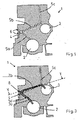
- a crankshaft bearing 2 and a camshaft bearing 3 and a main oil passage 4 are shown in cross section. Furthermore, longitudinally cut guide channels 5a, 5b can be seen which run from the main oil channel 4 to the crankshaft bearing 2 or camshaft bearing 3 and provide during engine operation for the lubrication of camshaft and crankshaft bearings.
- the outgoing from the camshaft bearing 3 guide channel 5c leads to an attachment of the cylinder crankcase 1, in this case to a cylinder head, not shown.
- the illustrated guide channels 5a, 5b, 5c are subsequently introduced into the cast cylinder crankcase 1, ie drilled. Therefore, only a straight course of the guide channels 5 is possible, and the housing 1 has manufacturing-related access 6 to the outside (to recognize left), which are to be closed later.
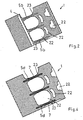
- Fig. 2 is the main oil channel 4 off Fig. 1 cut longitudinally, and there are several of them branching guide channels 5b, which lead to bearings 3 for the camshaft to recognize. Furthermore, recesses 22 in the contour region of the cylinder crankcase 1 shown. Corresponding recesses 22 are also in the Fig. 4 and 6 to recognize.
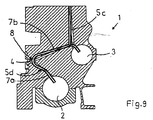
- Fig. 3 shows a cast component for an internal combustion engine having at least one guide channel 5, which forwards a fluid medium to a demand site. And it is a cylinder crankcase 1. The cutting position corresponds to that of Fig. 1 ,
- a guide channel 5d which has been formed in the form of a tube and poured in during casting of the cylinder crankcase 1 with.
- the single connecting tube 7, which is cast in as a guide channel 5d, is bent here in a "handle-like manner".
- a guide channel 5 d also have a different shape or a different course than shown.
- a section 7a extends to a crankshaft bearing 2 and another section 7b to a camshaft bearing 3.
- the bend 8 is located at the point where the main oil channel 4, which in this embodiment is drilled in a conventional manner is subsequently introduced, will run.
- crankshaft bearings can be supplied with oil via a tube guide channel or a plurality of tube guide channels, and the camshaft bearings can be supplied by mechanically introduced channels in the conventional way.
- the main oil passage 4 and the guide channels 5 are formed to the camshaft bearings 3 and crankshaft bearings 2 as cast-in tubes, and this is realized by a branched, cast-pipe system 9.
- pipes with the appropriate dimensions length, diameter, cross-sectional shape, etc. have been connected before casting to a pipe system 9, which has subsequently been poured in a suitable casting process.
- the cast-in as tubes guide channels 5 is not completely of casting material be surrounded, ie run in the component, must, but can also be partially exposed. Furthermore, the guide channels 5 may also have a curved, adapted to the contour course course.
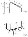
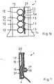
- Fig. 7 shows a connecting tube 7 for a "suitcase handle" guide channel 5d in different views.
- the to be recognized core supports 10 serve the lateral support during the casting process. However, it is also possible to do without core supports 10, for example, if the ends of the connecting tube 7 are anchored sufficiently firmly in casting cores.
- Fig. 8 shows an example of a pipe system 9. From a main guide channel 9a branch off several secondary ducts 9b, which lead to the individual needs and supply them with the appropriate medium.
- crankcase 1 are - according to the first example of the Fig. 3 and 4 -
- Several individual, "suitcase-like" connecting pipes 7 have been poured as a guide channels 5d during casting of the housing.
- the sections 7a, 7b while the crankshaft bearing 2 and the camshaft bearing 3 are supplied from the subsequently introduced by drilling main oil passage 4, which intersects the connecting pipes 7, respectively, with lubricant.
- the guide channels 5c to the cylinder heads are not subsequently bored in the cylinder crankcase 1, but also realized in the form of casting the housing with cast-in pipes, whereby advantageously an additional post-processing step is saved on the casting.
- a connecting pipe 7 and a pipe for the formation of the guide channel 5c have been connected to each other before pouring.
- a guide channel 5c to the cylinder head also branch off from a connecting pipe 7 at a location other than shown. It is also possible that a guide channel 5c is not fed via a connecting pipe 7 with lubricant, but directly from the drilled main oil passage 4 (eg, by pouring into the formation of guide channels 5c for supplying the cylinder heads separate, correspondingly positioned pipes). Furthermore, the leading to the cylinder heads, designed as a cast-in tubes guide channels 5c part of a cast-pipe system (corresponding to that in the FIGS. 5 and 6 Example shown) and branch off either directly from the tubular main oil passage 4 or sub-guide channels 9b.
- a tubular guide channel 5c not branch off from the main oil passage 4, a connecting pipe 7, a secondary guide channel 9b, etc., but in the area of a bearing (here, for example, the camshaft bearing 3, but other bearings are possible) in a groove of a bearing ring and from There are lubricants supplied.
- Fig. 10 shows a cylinder crankcase 1 according to the invention as a cast component for an internal combustion engine. Laterally visible oil sump connection surfaces 14 to which an oil sump is fastened.
- the cylinder crankcase 1 has at least one guide channel 5e, which forwards a fluid medium to a point of need, is formed in the form of a pipe and is cast in during the casting of the cylinder crankcase 1.
- the guide channel 5e cast in as a tube forms an oil feed line 11 for the piston cooling, ie it conducts oil as a fluid medium to a point of need.
- the oil supply line 11 ends here via a recess 21 on an end face 15 of the cylinder crankcase 1 and is from an oil pump supplied with oil.
- lubricant could be fed into the oil supply line 11 at another point of the oil circuit within the cylinder crankcase 1.
- the cast-in pipe guide channel 5e is arranged in the longitudinal extension of the cylinder crankcase 1, ie transversely to the cylinders 12. He runs here in the area of the crank chambers at the lower cylinder areas at a certain distance from the Zylinderau Consujar. It can be seen that the guide channel 5e is adapted to the shape of the cylinder 12, so that there is a "wave-like" curved course.
- the oil supply line 11 is formed in the embodiment substantially exposed. In several places it is locally looped with casting material of the component. These Gußhalterept 13 cause a solid composite of oil supply 11 and component.
- the Gußhalterept 13 here form the mounting points for the spray nozzles, not shown.
- the spray nozzles are subsequently introduced mechanically into the oil feed line 11 and in each case designed and arranged such that they inject lubricant directed into a cylinder space under a piston crown. This cools the pistons and lubricates the cylinder walls.
- oil supply line 11 could also have a different course or another arrangement.
- several guide channels 5e which form oil supply lines 11 for the piston cooling, could also be cast. If necessary, the oil supply line 11 could also advantageously have different cross-sectional shapes in their course.
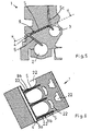
- Fig. 11 shows a cylinder crankcase 1 as a cast component for an internal combustion engine, which has at least one guide channel 5f, which forwards a fluid medium to a demand site, formed in the form of a tube and cast in the casting of the cylinder crankcase 1 with.
- the guide channel 5f cast in as a tube forms a pressure oil line 16 to a cylinder head.
- the cast as a pipe pressure oil line 16 is supplied directly here by a main oil passage 4 with lubricant.
- the connection of the guide channel 5f is made to the oil circuit in the cylinder crankcase 1 shown.
- the pressure oil line 16 could be fed from another area of the oil balance within the cylinder crankcase 1 by, for example, before being poured into the cylinder crankcase with another oil-carrying line has been connected to a composite pipe (see. Fig. 9 ) or by opening into a groove of a bearing. Numerous other advantageous variants are possible.
- a threaded bore 18 and another recess 19 - has the cast as a tube guide channel 5f adapted to the contour course course and here "curved" bent.
- the pressure oil line 16 is completely surrounded here in longitudinal extension with casting material.
- it could, depending on the design conditions, advantageously also be arranged such that it runs partially or completely exposed in parts.
- it could advantageously have different cross-sectional shapes in its course, e.g. To overcome bottlenecks in the cylinder crankcase 1.
- the appropriate number of cast as a pipe pressure oil lines 16 for the oil supply of the cylinder head and the cylinder heads on the cylinder crankcase 1 depends on the respective assembly of the engine.
- the Fig. 12a and 12b show yet another advantageous cylinder crankcase 1 as a cast component for an internal combustion engine, which has at least one guide channel 5g, which forwards a fluid medium to a demand site, formed in the form of a tube and is molded during casting of the cylinder crankcase 1 with.
- This cast in as a pipe Guide channel 5g forms a fuel line 24 for the supply of a fuel pump with fuel as a fluid medium. Due to the curved line 25 is in Fig. 12a indicated that the representation of the cast-in fuel line 24 is located in a different sectional plane than the rest of the drawing.
- guide channels 5g are each cast as a tube in an outer wall 26 of the cylinder crankcase 1, and that they extend in the longitudinal extension of the cylinder crankcase 1 (vg1. Fig. 12b ).
- the middle fuel line 24 is a fuel supply line and the outer fuel lines 24 are each a fuel return line.
- a recess 27 shown in the later a fuel pump is used.
- a plurality of recesses 27 are provided for fuel pumps over the length of the central fuel line 24, wherein the number depends on the number of cylinders of the respective engine.
- the fuel supply line is cut or severed in each case in the areas of the recesses 27 for the fuel pumps, thereby producing the connections between the guide channel 5g and pumps. Openings in the fuel return lines are later also mechanically introduced.
- each fuel is removed from the supply line and pumped through a connection line to an injection nozzle in a cylinder head.
- fuel lines are mechanically introduced into the outer wall of a cylinder crankcase as long, straight holes.
- the pouring of one or more fuel pipe (s) as a pipe with said manufacturing method offers the advantageous possibility that the guide channel, if necessary, can be bent. It may advantageously be exposed predominantly or in sections, may not also have round cross-sectional shapes or have different cross-sectional shapes in its course. Thereby, e.g. a reduction in the component wall thickness possible, resulting in savings in material and weight and reduced manufacturing costs.
- the course of the lines can be optimized. Since the fuel line (s) 24 are already integrated in the finished cast component, the workload is also significantly reduced overall.
- FIG. 13 An example of such an advantageous combination shows Fig. 13 , There is a cylinder crankcase 1 can be seen, in which the supply of crankshaft bearings 2 and 3 camshaft bearings with lubricant is realized by cast into the bulkheads 23 curved guide channels 5d (corresponding to that in the Fig. 3 and 4 example described).
- a cast-in as a pipe guide channel 5c is provided, which forms a pressure oil pipe 16 to a cylinder head. Unlike in the Fig. 11 shown example, this is not supplied directly from the main oil channel 4 with oil, but branches off from the cast-guide channel 5d.
- guide tubes 5g cast in as tubes are provided, which form fuel lines 24 (supply line and return lines) for the supply of a fuel pump (corresponding to the exemplary embodiment of FIG Fig. 12 ).
- a cast-in bearing supply via separate connecting pipes 7 or a cast-in pipe system 9 i.V.m. a cast supply line 11 for the piston cooling; a cast-in supply line 11 for the piston cooling i.V.m. a cast-in fuel line 24; a cast-in pressure oil line 16 to the cylinder head i.V.m. a cast-in fuel line 24, etc.
- the guide channels illustrated in the exemplary embodiments by way of example for the oil supply and the fuel supply 5 can be transferred accordingly to guide channels 5 for another medium.
- cylinder crankcase 1 wherein the cylinder crankcase may be formed in one or more parts or it may also be a crankcase with attached cylinder housing.
Abstract
Description
Die Erfindung betrifft ein gegossenes Bauteil für eine Brennkraftmaschine, wobei es sich bei dem Bauteil um ein Zylinderkurbelgehäuse handelt, das mindestens einen Führungskanal aufweist, der in Form eines Rohres ausgebildet und beim Gießen des Bauteiles mit eingegossen ist und der ein fluides Medium zu einer Bedarfstelle weiterleitet, wobei es sich bei dem fluiden Medium um Öl handelt.The invention relates to a cast component for an internal combustion engine, wherein the component is a cylinder crankcase having at least one guide channel, which is formed in the form of a tube and molded during casting of the component and which forwards a fluid medium to a demand site wherein the fluid medium is oil.
Brennkraftmaschinen sind in Form von Verbrennungsmotoren wesentlicher Bestandteil von Fahrzeugen (z.B. PKW und Nutzfahrzeuge, Schiffe etc.) und kommen auch als stationäre Motore zum Einsatz. Dabei enthalten Brennkraftmaschinen zahlreiche gegossene Bauteile, die mindestens einen Führungskanal (auch Versorgungsleitung genannt) aufweisen, der ein fluides Medium (z.B. Öl, Wasser Gas oder andere flüssige bzw. gasförmige Medien) zu einer Bedarfstelle im Motor bzw. in angrenzenden Bereichen weiterleitet. Manche der Führungskanäle können auch selbst der Kühlung eines Bauteils dienen. Bedarfstellen sind die Orte, an denen das jeweilige Medium benötigt wird, z.B. zu schmierende Lager, zu kühlende Bereiche usw.Internal combustion engines, in the form of internal combustion engines, are an integral part of vehicles (for example cars and commercial vehicles, ships, etc.) and are also used as stationary engines. In this regard, internal combustion engines include numerous molded components having at least one guide channel (also called a supply line) which relays a fluid medium (e.g., oil, water gas, or other liquid or gaseous media) to a demand site in the engine or adjacent areas. Some of the guide channels can also be used to cool a component itself. Where needed are the locations where the particular medium is needed, e.g. bearings to be lubricated, areas to be cooled, etc.
Ein Führungskanal bzw. mehrere Führungskanäle kommt/kommen insbesondere in einem Zylinderkurbelgehäuse bzw. dazu benachbarten Anbauteilen vor. Führungskanäle werden in bekannter Weise durch mechanische Bearbeitung auf Werkzeugmaschinen bzw. Transferstraßen eingebracht, d.h. gebohrt. Dazu werden in mehreren aufwendigen, hochpräzise auszuführenden Arbeitsschritten zentrale Hauptführungskanäle und Nebenführungskanäle, die Abzweigungen zu den einzelnen Bedarfstellen bilden, in das Bauteil gebohrt. Anschließend müssen zahlreiche, nicht benötigte Zugänge dauerhaft und sicher verschlossen werden. Sehr lange, geradlinige Führungskanäle, wie die des Hauptölkanales bei einem Zylinderkurbelgehäuse werden heute auch schon vereinzelt gegossen durch Umgießen eines Rohres oder durch Freisparen durch einen entsprechenden Gießkern.A guide channel or a plurality of guide channels comes / come especially in a cylinder crankcase or adjacent thereto add-on parts. Guide channels are introduced in a known manner by mechanical processing on machine tools or transfer lines, ie drilled. These are done in several elaborate, high-precision work steps Central main ducts and sidetracking channels, which make junctions to individual needs sites, are drilled into the component. Subsequently, numerous, unnecessary accesses must be closed permanently and safely. Very long, linear guide channels, such as those of the main oil passage in a cylinder crankcase are today even occasionally poured by pouring a pipe or by saving by a corresponding casting core.
Aus der
Die
In der
Der Erfindung liegt die Aufgabe zugrunde, bei einem Bauteil - und zwar einem Zylinderkurbelgehäuse - der oben genannten Art den Herstellungs- und Kostenaufwand zu verringern.The invention is based on the object in a component - namely a cylinder crankcase - the above-mentioned type to reduce manufacturing and cost.
Diese Aufgabe wird bei einem gegossenen Bauteil der oben genannten Art erfindungsgemäß durch die kennzeichnenden Merkmale des Anspruches 1 gelöst.This object is achieved according to the invention in a cast component of the type mentioned above by the characterizing features of
Erfingdungsgemäß handelt es sich bei dem gegossenen Bauteil um ein Zylinderkurbelgehäuse. Ein Zylinderkurbelgehäuse weist zahlreiche Führungskanäle insbesondere für Öl und Wasser auf, so daß durch das Eingießen eines Führungskanales oder mehrerer Führungskanäle, der bzw. die jeweils als Rohr ausgebildet ist/sind, eine erhebliche Einsparung an Herstellungsaufwand erreicht wird. Dabei handelt es sich im Falle eines einzigen als Rohr eingegossenen Führungskanales nicht um den Hauptölkanal, da dies zum Stand der Technik gehört. Ziel der Erfindung ist es vielmehr, (ggf. neben dem Eingießen des Hauptölkanales als Rohr) einen anderen Führungskanal oder mehrere andere Führungskanäle für Öl bzw. andere Medien zu Bedarfstellen als Rohr(e) einzugießen. Als wesentlicher Führungskanal zu Bedarfstellen bei einem Zylinderkurbelgehäuse, der erfindungsgemäß in Form eines eingegossenen Rohres realisiert werden kann, ist die Zuleitung für die Kolbenkühlung zu nennen. Als weitere wesentliche Führungskanäle zu Bedarfstellen bei einem Zylinderkurbelgehäuse, die in Form eingegossener Rohre vorteilhaft realisiert werden können, sind z.B. die Ölzuleitungen zu Kurbelwellen- bzw. Nockenwellenlagern, die Druckölleitung zum Zylinderkopf oder Ölrückläufe zu nennen.According to the invention, the cast component is a cylinder crankcase. A cylinder crankcase has numerous guide channels, especially for oil and water, so that by pouring a guide channel or more guide channels, which is or in each case designed as a tube, a considerable saving in manufacturing effort is achieved. In the case of a single guide channel cast in as a pipe, this is not the main oil channel, since this belongs to the state of the art. Object of the invention it is rather, (possibly next to the pouring of the main oil passage as a pipe) to pour another guide channel or more other channels for oil or other media to need as a pipe (e). As an essential guide channel to need points in a cylinder crankcase, which can be realized according to the invention in the form of a cast-in tube, the supply line for the piston cooling is called. As a further essential guide channels to need in a cylinder crankcase, which can be advantageously realized in the form of cast-in tubes, for example, the oil supply to crankshaft or camshaft bearings, the pressure oil line to the cylinder head or oil returns to call.
Ferner kann mindestens ein Führungskanal als Rohr in das Zylinderkurbelgehäuse eingegossen sein, der eine Kraftstoffleitung bildet.Furthermore, at least one guide channel can be cast as a pipe in the cylinder crankcase, which forms a fuel line.
Das Eingießen eines vorgefertigten Rohres als Führungskanal hat gegenüber dem mechanischen Einbringen durch Bohren den Vorteil, daß der Führungskanal nicht geradlinig (wie beim Bohren) zu verlaufen braucht, sondern an den erforderlichen Konturenverlauf des Bauteiles mit den jeweils gewünschten Biegungen angepaßt werden kann. Im Unterschied dazu müssen beim geradlinigen Bohren eines Führungskanales gemäß dem Stand der Technik zwangsläufig Bearbeitungswege getätigt werden, die nicht der Versorgung der Bedarfstelle dienlich sind. Ferner weist eine Bohrung einen Zugang nach außen auf, der nachträglich wieder verschlossen werden muß, was zu Dichtigkeitsproblemen führen kann. Derartige Nachteile und Probleme treten bei einem in Form eines entsprechend vorgefertigten bzw. geformten Rohres eingegossenen Führungskanal nicht auf.Pouring a prefabricated pipe as a guide channel has over the mechanical introduction by drilling the advantage that the guide channel does not need to be straight (as drilling), but can be adapted to the required contour of the component with the respective desired bends. In contrast, in the straight-line drilling of a guide channel according to the prior art inevitably machining paths must be made that are not useful to supply the need site. Furthermore, a bore has an access to the outside, which must be subsequently closed again, which can lead to leakage problems. Such disadvantages and problems do not occur in a cast in the form of a corresponding prefabricated or molded tube guide channel.
Ein weiterer Vorteil der Erfindung liegt darin, daß ein eingegossener Rohr-Führungskanal bzw. mehrere eingegossene Rohr-Führungskanäle ein Höchstmaß an Sauberkeit an der inneren Kanalwandung bietet/bieten und der Hohlraum im Unterschied zum Stand der Technik frei von Rückständen infolge eines mechanischen Einbringens des Kanals bzw. frei von Gießrückständen (z.B. Kernrückständen) infolge eines Eingießens des Kanales in das Bauteil als Hohlraum durch Einlegen eines Kernes ist.Another advantage of the invention is that a cast-pipe guide channel or more cast-pipe guide channels offers a high degree of cleanliness on the inner channel wall and the cavity unlike the prior art free from residues due to mechanical introduction of the channel or free of casting residues (eg core residues) due to a pouring of the channel into the component as a cavity by inserting is a kernel.
Dieser Aspekt ist bei einem Führungskanal zur Lagerschmierung besonders wichtig, da im Kanal ggf. verbliebene Rückstände mit dem Öl beim Motorbetrieb in das Lager gelangen und zur Zerstörung des Lagers führen würden.This aspect is particularly important in a guide channel for bearing lubrication, as in the channel possibly remaining residues with the oil during engine operation in the camp and would lead to the destruction of the bearing.
Darüber hinaus ist es im Unterschied zu einem gebohrten Führungskanal, bei dem nur kreisrunde Querschnitte realisierbar sind, möglich, den Kanal mit nahezu jeder gewünschten Querschnittsform einzubringen und dadurch den Verlauf und die Versorgung zu optimieren. Ferner kann durch geeignete Wahl der Querschnittsform auch die Stärke der Bauteilwandung, in der der Führungskanal eingegossen ist, reduziert werden, was zu einer Gewichtsreduktion des Bauteiles führt.In addition, in contrast to a drilled guide channel, in which only circular cross-sections are feasible, it is possible to introduce the channel with almost any desired cross-sectional shape and thereby optimize the course and the supply. Furthermore, by suitable choice of the cross-sectional shape and the strength of the component wall, in which the guide channel is cast, can be reduced, resulting in a weight reduction of the component.
Selbstverständlich ist es möglich, an demselben Bauteil einen oder mehrere erfindungsgemäß als Rohr eingegossene Führungskanäle und einen oder mehrere auf herkömmlichem Wege eingebrachte Führungskanäle vorzusehen.Of course, it is possible to provide on the same component one or more according to the invention cast as a tube guide channels and one or more introduced in a conventional manner guide channels.
Bei dem erfindungsgemäßen Zylinderkurbelgehäuse nach Anspruch 1 ist mindestens ein Führungskanal als Rohr eingegossen, der eine Ölzuleitung für die Versorgung der Kolbenkühlung bzw. Schmierung der Zylinderwandung bildet. Bei der Erfindung ist der mindestens eine als Rohr eingegossene Führungskanal derart angeordnet, daß er streckenweise ganz oder teilweise freiliegend verläuft, d.h. er kann außerhalb der Bauteilwandung auf dessen Außenseite bzw. Innenseite verlaufen. Örtlich kann der Führungskanal dagegen schellenartig mit Gußmaterial des Bauteils umgossen sein, um für den festen Verbund von Kanal und Bauteil zu sorgen. Der Führungskanal kann (bezogen auf seine. Längserstreckung) vollständig freiliegend verlaufen oder aber teilweise mit in die Bauteilwandung eingegossen sein. Die Maßnahme des streckenweise freiliegenden Verlaufes bietet gegenüber dem Stand der Technik, in dem die gebohrten oder mit Kernen eingegossenen Führungskanäle nur in der Wandung des Bauteiles verlaufen können, den Vorteil, daß die Wandstärke des Bauteiles erheblich reduziert und dadurch an Material und Gewicht eingespart werden kann.In the cylinder crankcase according to the invention according to
Für die Einsparung an Arbeitsaufwand ist es vorteilhaft, wenn mehrere Kolben bzw. Zylinder von einer gemeinsamen Ölzuleitung aus versorgt werden. Dafür kann die Ölzuleitung zweckmäßig derart ausgebildet und angeordnet sein, daß sie in Längserstreckung des Zylinderkurbelgehäuses verläuft und von ihr mehrere Spritzdüsen abzweigen, die Öl gerichtet jeweils in einen Zylinderraum unter einen Kolbenboden spritzen, wodurch zum einen der Kolbenboden gekühlt und zum anderen die betreffende Zylinderwandung geschmiert wird. Selbstverständlich können auch mehrere Ölzuleitungen zu einem Zylinder oder zu mehreren Zylindern mit ggf. anderen Verläufen eingegossen sein.For saving labor, it is advantageous if a plurality of pistons or cylinders are supplied by a common oil supply from. For this purpose, the oil supply can be suitably designed and arranged such that it extends in the longitudinal extension of the cylinder crankcase and branch off several spray nozzles, the oil directed each injected into a cylinder space below a piston head, thereby cooling the piston crown on the one hand and lubricated on the other the respective cylinder wall becomes. Of course, it is also possible for a plurality of oil supply lines to be cast into a cylinder or to a plurality of cylinders, possibly with other progressions.
Je nach gegossenem Zylinderkurbelgehäuse kann es zweckmäßig sein, an dem Bauteil nur einen einzigen als Rohr eingegossenen Führungskanal vorzusehen. Vorteilhafterweise umfaßt das Bauteil mehrere eingegossene Führungskanäle, um Fertigungs- und Kostenaufwand einzusparen. In einer vorteilhaften Variante können die Führungskanäle jeweils als einzelnes Verbindungsrohr für die Mediumführung eingebracht sein. D.h. es werden beim Gießen mehrere einzelne, entsprechend geformte Rohre als Verbindungsteile mit eingegossen. Dies bietet ein hohes Maß an Freiheit hinsichtlich des Verlaufes der Führungskanäle. Gemäß einer weiteren alternativen vorteilhaften Variante sind die eingegossenen Führungskanäle durch ein verzweigtes Rohrsystem realisiert. Dafür sind vor dem Gießen mehrere Rohre zu einem Rohrsystem miteinander verbunden (z.B. verschweißt) und anschließend der Rohrverbund mit eingegossen worden. Auch eine Kombination von Führungskanälen in Rohrverbundform und einzelnen Verbindungsteilen an demselben Bauteil ist möglich und vorteilhaft.Depending on the cast cylinder crankcase, it may be appropriate to provide only a single cast as a pipe guide channel on the component. Advantageously, the component comprises a plurality of cast guide channels in order to save manufacturing and cost. In an advantageous variant, the guide channels can be introduced in each case as a single connecting tube for the medium guide. This means that when pouring several individual, correspondingly shaped tubes are cast as connecting parts with. This provides a high degree of freedom in terms of the course of the guide channels. According to In another alternative advantageous variant, the cast-in guide channels are realized by a branched pipe system. For this purpose, several pipes to a pipe system are connected to each other (eg welded) before pouring and then the pipe assembly has been cast with. A combination of guide channels in pipe composite form and individual connecting parts on the same component is possible and advantageous.
Gemäß einer vorteilhaften Ausführung der Erfindung weist das Zylinderkurbelgehäuse mindestens einen als Rohr eingegossenen Führungskanalauf, der eine Kraftstoffleitung für die Versorgung einer Kraftstoffpumpe bildet. Die Kraftstoffleitung verläuft vorteilhafterweise in Längserstreckung des Zylinderkurbelgehäuses im Bereich einer Gehäuseaußenwand. In einer vorteilhaften Weiterbildung sind mehrere Kraftstoffleitungen als Rohre eingegossen, z.B. mindestens eine Zufuhrleitung und mindestens eine Rücklaufleitung.According to an advantageous embodiment of the invention, the cylinder crankcase at least one cast-in as a tube guide channel, which forms a fuel line for the supply of a fuel pump. The fuel line advantageously extends in the longitudinal extension of the cylinder crankcase in the region of a housing outer wall. In an advantageous development, a plurality of fuel lines are cast as tubes, e.g. at least one supply line and at least one return line.
Gemäß einer vorteilhaften Weiterbildung der Erfindung weist der mindestens eine eingegossene Führungskanal in seinem Verlauf unterschiedliche Querschnittsrormen auf. Dadurch wird eine gute Anpassung an die jeweilige Konstruktion des Bauteiles erreicht. Beispielsweise können enge Konturbereiche überwunden werden. Die jeweils zu verwirklichenden Querschnittsformen richten sich nach der jeweiligen Konstruktion des Bauteiles. Unterschiedliche Querschnittsformen an einem Rohr lassen sich vor dem Eingießen z.B. durch Hydroumformung des Rohres realisieren.According to an advantageous development of the invention, the at least one cast-in guide channel has different cross-sectional shapes in its course. As a result, a good adaptation to the respective construction of the component is achieved. For example, narrow contour areas can be overcome. The respective cross-sectional shapes to be realized depend on the particular construction of the component. Different cross-sectional shapes on a tube can be removed prior to pouring e.g. realize by hydroforming of the tube.
Gemäß einer vorteilhaften Ausführung der Erfindung ist das Bauteil aus einem metallischen Werkstoff oder Kunststoff gefertigt. Ebenso kann vorteilhafterweise der mindestens eine eingegossene Führungskanal aus einem metallischen Werkstoff oder Kunststoff gefertigt sein. Als metallische Werkstoffe kommen z.B. Stahl, sämtliche Gußeisenwerkstoffe, Leichtmetalle, Buntmetalle in Frage. Welcher Werkstoff im einzelnen vorzugsweise einzusetzen ist, hängt u.a. auch von dem jeweils zu gießenden Bauteil ab.According to an advantageous embodiment of the invention, the component is made of a metallic material or plastic. Likewise, advantageously, the at least one cast guide channel made of a metallic material or plastic. As metallic materials such as steel, all cast iron materials, light metals, non-ferrous metals come into question. Which material is to be preferably used in particular also depends, inter alia, on the particular component to be cast.
Selbstverständlich können gemäß der Erfindung ausgebildete und angeordnete eingegossene Rohre als Führungskanäle auch in einem Anbauteil eines Zylinderkurbelgehäuses - insbesondere in einem Zylinderkopf, einem Getriebegehäuse, einem Rädergehäuse, einer Ölwanne oder dergleichen - verwirklicht sein. Dabei können Führungskanäle im Zylinderkurbelgehäuse bzw. in dem/den Anbauteil(en) von einem gemeinsamen oder mehreren Versorgungskreisläufen versorgt werden.Of course, according to the invention trained and arranged cast-in tubes can be realized as a guide channels in an attachment of a cylinder crankcase - in particular in a cylinder head, a gear housing, a gear housing, an oil pan or the like. In this case, guide channels in the cylinder crankcase or in the / the attachment (s) can be supplied by a common or multiple supply circuits.
Ein Verfahren zum Herstellen eines gegossenen Bauteiles für eine Brennkraftmaschine, wobei es sich bei dem Bauteil um ein Zylinderkurbelgehäuse handelt, das mindestens einen Führungskanal aufweist, der ein fluides Medium zu einer Bedarfstelle weiterleitet, sieht vor, daß für die Bildung des mindestens einen Führungskanales ein Rohr mit dem gewünschten Verlauf in eine zum Gießen benötigte Gießform eingebaut oder in einen Gießkern eingebracht oder in ein verlorenes Modell bzw. in dessen Formmedium-Hohlraumfüllung eingearbeitet wird und anschließend das Bauteil mit dem jeweils einzusetzenden Gießverfahren gegossen wird.A method for producing a cast component for an internal combustion engine, wherein the component is a cylinder crankcase having at least one guide channel which forwards a fluid medium to a demand site, provides that a tube is used to form the at least one guide channel is incorporated with the desired course in a mold required for casting or introduced into a casting core or incorporated into a lost model or in the molding medium cavity filling and then the component is poured with the casting method to be used in each case.
Dabei kann das Rohr auch in mehreren Gießkernen eingebracht sein, die als Einzelkerne zu einem Kernblock montiert sein können.In this case, the tube can also be incorporated in several casting cores, which can be mounted as individual cores to form a core block.
Durch dieses Gießkonzept ist es möglich, ein Zylinderkurbelgehäuse mit mindestens einem eingegossenen Rohr-Führungskanal herzustellen, aber auch andere Bauteile wie Anbauteile für das Zylinderkurbelgehäuse (z.B. Zylinderkopf, Getriebegehäuse, Rädergehäuse, Ölwanne etc.) sind vorteilhaft zu verwirklichen. Je nachdem, ob der mindestens eine Führungskanal vollständig in die Bauteilwandung eingegossen oder ganz oder teilweise freiliegend sein soll, wird das einzugießende Rohr in die Gießform (ggf. mittels Stützen) eingebaut bzw. in den Gießkern eingebracht (z.B. in einen sandkern eingeschossen oder bei der Kernherstellung mit eingearbeitet) oder in ein verlorenes Modell eingearbeitet bzw. in dessen lose Formmedium-Hohlraumfüllung direkt eingebettet, oder das Rohr wird an einem Rohrende in dem Gießkern gelagert. Beim Einbringen eines Rohres in den Gießkern sind bestimmte Bereiche wieder freizulegen, um eine feste Gußverbindung mit dem Bauteil zu erzeugen. Nach dem Gießen mit dem jeweils einzusetzenden Gießverfahren wird das gegossene Rohteil aus der Form entnommen, Kerne bzw. loses Formmedium entfernt, und es erfolgen die üblichen Nachbearbeitungsmaßnahmen.Through this casting concept, it is possible to produce a cylinder crankcase with at least one cast-pipe guide channel, but also other components such as attachments for the Cylinder crankcases (eg cylinder head, gearbox housing, wheel housing, oil sump, etc.) are advantageous to realize. Depending on whether the at least one guide channel is to be completely cast into the component wall or completely or partially exposed, the einzugießende pipe is installed in the mold (possibly by means of supports) or introduced into the casting core (eg injected into a sand core or in the Core manufacturing incorporated with) or incorporated into a lost model or directly embedded in the loose mold medium cavity filling, or the tube is mounted at a pipe end in the casting core. When introducing a tube into the casting core, certain areas must be exposed again in order to produce a firm cast connection with the component. After casting with the particular casting method to be used, the cast blank is removed from the mold, cores or loose molding medium are removed, and the usual post-processing measures are carried out.
Ein erfindungsgemäßes, gegossenes Bauteil kann mit unterschiedlichen Gießverfahren gefertigt werden. Gemäß einer ersten vorteilhaften Verfahrensvariante wird das Bauteil in einem Gießverfahren mit verlorener Form gegossen, z.B. in einem reinen Kernform-Verfahren, einem Kernform- i.V.m. Grünform-Verfahren, Kernform- i.V.m. Kaltharzform-Verfahren usw. Nach einer zweiten vorteilhaften Verfahrensvariante wird das Bauteil in einem Gießverfahren mit Dauerform gegossen, z.B. Kokillen-Guß, Druckguß, Spritzguß usw. In einer dritten bevorzugten Variante wird das Bauteil im Lost Foam Verfahren gegossen. Vorteile des Lost Foam Gießverfahrens (eine Form des Vollformgießens) sind beispielsweise das Fehlen von Kernrückständen am gegossenen Bauteil, die hohe Oberflächenqualität, hochwertige Konturschärfe und große Abbildungsgenauigkeit und damit ein relativ geringer Nachbearbeitungsaufwand.A cast component according to the invention can be manufactured with different casting methods. According to a first advantageous variant of the method, the component is cast in a casting process with lost shape, for example in a pure core molding process, a Kernform- iVm green mold process, Kernform- iVm cold resin molding process, etc. According to a second advantageous method variant, the component in a Continuous casting process, eg mold casting, die casting, injection molding, etc. In a third preferred variant, the component is cast in the lost foam process. Advantages of the Lost Foam casting process (a form of full-cast casting) are, for example, the lack of core residues on the cast component, the high surface quality, high-quality contour definition and great imaging accuracy, and thus a relatively low reworking effort.
Falls das Bauteil mehrere eingegossene Führungskanäle aufweisen soll, können die dafür benötigten Rohre vorzugsweise als einzelne Verbindungsrohre eingebracht werden. Auch kann es vorteilhaft sein, mehrere Rohre zu einem entsprechenden Rohrsystem zu verbinden, das vorgefertigte Rohrsystem in Gießform, Kern usw. zu positionieren und anschließend mit einzugießen. Ferner kann es bei manchen Varianten vorteilhaft sein, mehrere Rohre jeweils zu einem Teilrohrsystem zu verbinden und mehrere Teilrohrsysteme in das Bauteil einzugießen. Welche Variante zu bevorzugen ist, hängt jeweils von der konkreten Aufgabenstellung ab.If the component is to have a plurality of cast-in guide channels, the tubes required for this purpose can preferably be introduced as individual connecting tubes. It may also be advantageous to connect a plurality of tubes to a corresponding pipe system, to position the prefabricated pipe system in the casting mold, core, etc., and then to pour it with. Furthermore, it may be advantageous in some variants to connect a plurality of tubes in each case to a partial tube system and to pour several partial tube systems into the component. Which variant is preferable depends on the specific task.
In den Zeichnungen sind Zylinderkurbelgehäuse schematisch dargestellt. Es zeigen:
- Fig. 1
- einen ausschnittsweisen Querschnitt aus einem Zylinderkurbelgehäuse nach dem Stand der Technik,
- Fig. 2
- einen ausschnittsweisen Längsschnitt zu
Fig. 1 (Stand der Technik), - Fig. 3
- einen ausschnittsweisen Querschnitt aus einem Zylinderkurbelgehäuse gemäß einem ersten Beispiel eines ersten Zylinderkurbelgehäuse-Typs,
- Fig. 4
- einen Längsschnitt zu
Fig. 3 entsprechend Y-Y, - Fig. 5
- einen ausschnittsweisen Querschnitt aus einem Zylinderkurbelgehäuse,
- Fig. 6
- einen Längsschnitt zu
Fig. 5 entsprechend X-X, - Fig. 7
- ein einzelnes Verbindungsrohr als einzugießender Führungskanal für ein Zylinderkurbelgehäuse,
- Fig. 8
- ein einzugießendes Rohrsystem für ein Zylinderkurbelgehäuse,
- Fig. 9
- einen ausschnittsweisen Querschnitt aus einem Zylinderkurbelgehäuse gemäß einem zweiten Beispiel des ersten Zylinderkurbelgehäuse-Typs,
- Fig. 10
- einen erfindungsgemäßen zweiten Zylinderkurbelgehäuse-Typ in schematischer Ansicht von unten,
- Fig. 11
- einen dritten Zylinderkurbelgehäuse-Typ in einem ausschnittsweisen Querschnitt,
- Fig. 12a
- einen vorteilhaften vierten Zylinderkurbelgehäuse-Typ in einem ausschnittsweisen Querschnitt,
- Fig. 12b
- einen ausschnittsweisen Längsschnitt entsprechend A-A aus
Fig. 12a und - Fig. 13
- ein weiteres Zylinderkurbelgehäuse in einem ausschnittsweisen Querschnitt.
- Fig. 1
- a partial cross-section of a cylinder crankcase according to the prior art,
- Fig. 2
- a partial longitudinal section to
Fig. 1 (State of the art), - Fig. 3
- 1 is a fragmentary cross-sectional view of a cylinder crankcase according to a first example of a first type of cylinder crankcase;
- Fig. 4
- a longitudinal section to
Fig. 3 according to YY, - Fig. 5
- a partial cross-section of a cylinder crankcase,
- Fig. 6
- a longitudinal section to
Fig. 5 according to XX, - Fig. 7
- a single connecting tube as einzugießender guide channel for a cylinder crankcase,
- Fig. 8
- a einzugießendes pipe system for a cylinder crankcase,
- Fig. 9
- 12 is a fragmentary cross-sectional view of a cylinder crankcase according to a second example of the first cylinder crankcase type;
- Fig. 10
- a second cylinder crankcase type according to the invention in a schematic view from below,
- Fig. 11
- a third type of cylinder crankcase in a fragmentary cross section,
- Fig. 12a
- an advantageous fourth cylinder crankcase type in a fragmentary cross section,
- Fig. 12b
- a partial longitudinal section corresponding to AA
Fig. 12a and - Fig. 13
- another cylinder crankcase in a fragmentary cross-section.
In dem in
In
Zu erkennen ist ein Führungskanal 5d, der in Form eines Rohres ausgebildet und beim Gießen des Zylinderkurbelgehäuses 1 mit eingegossen worden ist. Das als Führungskanal 5d eingegossene einzelne Verbindungsrohr 7 ist hier "koffergriffartig" gebogen ausgebildet. - Selbstverständlich kann ein Führungskanal 5d auch eine andere Formgebung bzw. einen anderen Verlauf als dargestellt haben. - Von einer Biegung 8 aus, verläuft dabei ein Abschnitt 7a zu einem Kurbelwellenlager 2 und ein anderer Abschnitt 7b zu einem Nockenwellenlager 3. Die Biegung 8 befindet sich an der Stelle, an der der Hauptölkanal 4, der bei diesem Ausführungsbeispiel auf herkömmliche Weise durch Bohren nachträglich eingebracht wird, verlaufen wird. Beim Einbringen des Hauptölkanales 4 durch Bohren wird das eingegossene Verbindungsrohr 7 durchbohrt und dadurch die Verbindung des Führungskanals 5d zum Hauptölkanal 4 hergestellt. Im Motorbetrieb gelangt Öl von dem Hauptölkanal 4 über die Abschnitte 7a, 7b des Führungskanales 5d bzw. Verbindungsrohres 7 zu dem jeweiligen Kurbelwellenlager 2 bzw. Nockenwellenlager 3. Die in das Nockenwellenlager 3 und das Kurbelwellenlager 2 hineinreichenden Enden des Führungskanales 5d sind gießtechnisch bedingt und werden im Rahmen der Nachbearbeitung entfernt. Der Führungskanal 5c zu dem Zylinderkopf ist bei diesem Ausführungsbeispiel durch Bohren eingebracht.Evident is a
In dem Längsschnitt in
Selbstverständlich ist es auch möglich, anstelle eines gebogenen Verbindungsrohres z.B. zwei separate Rohre einzugießen, von denen eines in ein Kurbelwellenlager und das andere in ein Nockenwellenlager mündet. Ferner ist es auch möglich, nur ein oder mehrere Nockenwellenlager über einen Rohr-Führungskanal oder mehrere Rohr-Führungskanäle mit Öl zu versorgen und die Kurbelwellenlager auf herkömmlichem Wege durch mechanisch eingebrachte Kanäle zu versorgen. Entsprechend kann/können ein oder mehrere Kurbelwellenlager über einen Rohr-Führungskanal oder mehrere Rohr-Führungskanäle mit Öl versorgt und die Nockenwellenlager auf herkömmlichem Wege durch mechanisch eingebrachte Kanäle versorgt werden.Of course, it is also possible, instead of a bent connecting pipe, e.g. pour two separate tubes, one opening into a crankshaft bearing and the other into a camshaft bearing. Furthermore, it is also possible to supply only one or more camshaft bearings via a pipe guide channel or a plurality of pipe guide channels with oil and to supply the crankshaft bearings in a conventional way by mechanically introduced channels. Accordingly, one or more crankshaft bearings can be supplied with oil via a tube guide channel or a plurality of tube guide channels, and the camshaft bearings can be supplied by mechanically introduced channels in the conventional way.
In dem in den
In den
Bei dem in
Selbstverständlich kann ein Führungskanal 5c zum Zylinderkopf auch an einer anderen Stelle als abgebildet von einem Verbindungsrohr 7 abzweigen. Ebenso ist es möglich, daß ein Führungskanal 5c nicht über ein Verbindungsrohr 7 mit Schmiermittel gespeist wird, sondern direkt vom gebohrten Hauptölkanal 4 (z.B. indem zur Ausbildung von Führungskanälen 5c zur Versorgung der Zylinderköpfe separate, entsprechend positionierte Rohre eingegossen werden). Ferner können auch die zu den Zylinderköpfen führenden, als eingegossene Rohre ausgebildeten Führungskanäle 5c Teil eines eingegossenen Rohrsystems (entsprechend dem in den
Im gezeigten Ausführungsbeispiel werden mehrere Zylinder 12 vorteilhaft von einer gemeinsamen Ölzuleitung 11 aus versorgt. Dafür ist der eingegossene Rohr-Führungskanal 5e in Längserstreckung des Zylinderkurbelgehäuses 1, also quer zu den Zylindern 12 angeordnet. Er verläuft hier im Bereich der Kurbelräume an den unteren Zylinderbereichen in gewissem Abstand zu den Zylinderaußenwandungen. Zu erkennen ist, daß der Führungskanal 5e an die Form der Zylinder 12 angepaßt ist, so daß sich ein "wellenartig" gebogener Verlauf ergibt. Die Ölzuleitung 11 ist in dem Ausführungsbeispiel im wesentlichen freiliegend ausgebildet. An mehreren Stellen ist sie örtlich schellenartig mit Gußmaterial des Bauteils umgossen. Diese Gußhalterungen 13 bewirken einen festen Verbund von Ölzuleitung 11 und Bauteil. Die Gußhalterungen 13 bilden hier auch die Montagestellen für die nicht dargestellten Spritzdüsen. Die Spritzdüsen werden nachträglich mechanisch in die Ölzuleitung 11 eingebracht und jeweils derart ausgebildet und angeordnet, daß sie Schmiermittel gerichtet in einen Zylinderraum unter einen Kolbenboden spritzen. Dadurch werden die Kolben zum einen gekühlt und zum anderen die Zylinderwandungen geschmiert.In the exemplary embodiment shown,
Wie in
Durch den gebogenen, angepaßten Verlauf der Ölzuleitung 11 für die Kolbenkühlung und durch deren überwiegend freiliegende, nur örtlich von Gußmaterial umgebene Ausbildung wird gegenüber den bekannten, geradlinig in Gußmaterial gebohrten Ölzuleitungen eine wesentliche Gewichtsreduktion des Bauteiles und Einsparung an mechanischem Bearbeitungsaufwand erzielt.Due to the curved, adapted course of the
Selbstverständlich könnte die Ölzuleitung 11 auch einen anderen Verlauf bzw. eine andere Anordnung aufweisen. Ferner könnten auch mehrere Führungskanäle 5e, die Ölzuleitungen 11 für die Kolbenkühlung bilden, eingegossen sein. Falls erforderlich, könnte die Ölzuleitung 11 in ihrem Verlauf auch vorteilhaft unterschiedliche Querschnittsformen aufweisen.Of course, the
Die als Rohr eingegossene Druckölleitung 16 wird hier direkt von einem Hauptölkanal 4 mit Schmiermittel versorgt. Durch das nachträgliche Bohren des Hauptölkanales 4 ist in dem gezeigten Zylinderkurbelgehäuse 1 die Anbindung des Führungskanales 5f an den ölkreislauf hergestellt. Alternativ könnte die Druckölleitung 16 auch von einem anderen Bereich des Ölhaushaltes innerhalb des Zylinderkurbelgehäuses 1 aus gespeist werden, indem sie z.B. vor dem Eingießen in das Zylinderkurbelgehäuse mit einer anderen ölführenden Leitung zu einem Rohrverbund verbunden worden ist (vgl.
Aufgrund eines Hindernisses 17 - exemplarisch dargestellt sind in dem gezeigten Beispiel eine Gewindebohrung 18 und eine andere Aussparung 19 - weist der als Rohr eingegossene Führungskanal 5f einen an den Konturenverlauf angepaßten Verlauf auf und ist hier "kurvenartig" gebogen. Selbstverständlich sind in Abhängigkeit konstruktiver Gegebenheiten andere Verlaufsformen möglich. Die Druckölleitung 16 ist hier in Längserstreckung vollständig mit Gußmaterial umgeben. Alternativ könnte sie, je nach konstruktiven Gegebenheiten vorteilhaft auch derart angeordnet sein, daß sie streckenweise ganz oder teilweise freiliegend verläuft. Ferner könnte sie in ihrem Verlauf vorteilhaft unterschiedliche Querschnittsformen aufweisen, um z.B. Engstellen im Zylinderkurbelgehäuse 1 zu überwinden.Due to an obstacle 17 - shown by way of example in the example shown, a threaded
Die in das Zylinderkurbelgehäuse 1 eingegossene Druckölleitung 16 zum Zylinderkopf endet an einer Zylinderkopfanschlußfläche 20. Die zweckmäßige Anzahl an als Rohr eingegossenen Druckölleitungen 16 für die Ölversorgung des Zylinderkopfes bzw. der Zylinderköpfe über das Zylinderkurbelgehäuse 1 hängt von der jeweiligen Bestückung des Motors ab.The appropriate number of cast as a pipe
Die Realisierung der Zylinderkopfölversorgung in Form eines eingegossenen Rohres bzw. mehrerer eingegossener Rohre ist für den Konstrukteur sehr vorteilhaft, da er seine Ölführung nicht geradlinig - wie im Falle des mechanischen Einbringens durch Bohren -, sondern gebogen und damit an die räumlichen Gegebenheiten angepaßt einbringen kann.The realization of the cylinder head oil supply in the form of a cast-in pipe or several cast-in pipes is very advantageous for the designer, since he his oil supply not straight - as in the case of mechanical introduction by drilling - but bent and thus can bring adapted to the spatial conditions.
Die
Zu erkennen ist, daß hier vorteilhaft mehrere Führungskanäle 5g jeweils als Rohr in eine Außenwand 26 des Zylinderkurbelgehäuses 1 eingegossen sind, und zwar verlaufen sie in Längserstreckung des Zylinderkurbelgehäuses 1 (vg1.
Im Zuge von Nachbearbeitungsmaßnahmen an dem gegossenen Bauteil wird in den Bereichen der Aussparungen 27 für die Kraftstoffpumpen jeweils die Kraftstoff-Zufuhrleitung angeschnitten bzw. durchtrennt und dadurch die Verbindungen zwischen Führungskanal 5g und Pumpen hergestellt. Öffnungen in den Kraftstoff-Rücklaufleitungen werden später ebenfalls mechanisch eingebracht. Durch eine Kraftstoffpumpe wird jeweils Kraftstoff aus der Zufuhrleitung entnommen und durch eine Anschlußleitung zu einer Einspritzdüse in einem Zylinderkopf gepumpt.In the course of finishing operations on the cast component, the fuel supply line is cut or severed in each case in the areas of the
Gemäß dem Stand der Technik werden Kraftstoffleitungen in die Außenwand eines Zylinderkurbelgehäuses mechanisch als lange, gerade Bohrungen eingebracht. Das Eingießen einer oder mehrerer Kraftstoffleitung(en) als Rohr mit dem genannten Herstellungsverfahren bietet die vorteilhafte Möglichkeit, daß der Führungskanal, falls erforderlich, gebogen sein kann. Er kann vorteilhaft überwiegend oder abschnittsweise freiliegend verlaufen, auch nicht runde Querschnittsformen aufweisen oder in seinem Verlauf unterschiedliche Querschnittsformen haben. Dadurch ist z.B. eine Reduktion der Bauteilwandungsstärke möglich, was zu Einsparungen an Material und Gewicht sowie zu verringerten Herstellungskosten führt. Ferner kann der Verlauf der Leitungen optimiert werden. Da die Kraftstoffleitung(en) 24 im fertig gegossenen Bauteil bereits integriert vorliegen, ist der Arbeitsaufwand darüber hinaus insgesamt erheblich reduziert.According to the prior art, fuel lines are mechanically introduced into the outer wall of a cylinder crankcase as long, straight holes. The pouring of one or more fuel pipe (s) as a pipe with said manufacturing method offers the advantageous possibility that the guide channel, if necessary, can be bent. It may advantageously be exposed predominantly or in sections, may not also have round cross-sectional shapes or have different cross-sectional shapes in its course. Thereby, e.g. a reduction in the component wall thickness possible, resulting in savings in material and weight and reduced manufacturing costs. Furthermore, the course of the lines can be optimized. Since the fuel line (s) 24 are already integrated in the finished cast component, the workload is also significantly reduced overall.
In dem in
Die vorstehend beschriebenen erfindungsgemäßen und vorteilhaften Ausführungen an den vier Zylinderkurbelgehäuse-Typen - und zwar a) Ölversorgung von Kurbelwellenlager bzw. Nockenwellenlager durch mehrere als Rohr eingegossene Führungskanäle (vgl.
Ein Beispiel einer derartigen vorteilhaften Kombination zeigt
Zahlreiche weitere Kombinationen sind vorteilhaft zu verwirklichen und werden von der Erfindung mit umfaßt, z.B. eine eingegossene Lagerversorgung über gesonderte Verbindungsrohre 7 oder ein eingegossenes Rohrsystem 9 i.V.m. einer eingegossenen Zuleitung 11 für die Kolbenkühlung; eine eingegossene Zuleitung 11 für die Kolbenkühlung i.V.m. einer eingegossenen Kraftstoffleitung 24; eine eingegossene Druckölleitung 16 zum Zylinderkopf i.V.m. einer eingegossenen Kraftstoffleitung 24 usw.Numerous other combinations are to be realized advantageously and are encompassed by the invention, e.g. a cast-in bearing supply via separate connecting
Die in den Ausführungsbeispielen exemplarisch für die Ölversorgung und die Kraftstoffversorgung dargestellten Führungskanäle 5 können entsprechend auch auf Führungskanäle 5 für ein anderes Medium übertragen werden.The guide channels illustrated in the exemplary embodiments by way of example for the oil supply and the
Die Erfindung wurde vorliegend für ein Zylinderkurbelgehäuse 1 beschrieben, wobei das Zylinderkurbelgehäuse einteilig oder mehrteilig ausgebildet sein kann bzw. es sich auch um ein Kurbelgehäuse mit aufgesetztem Zylindergehäuse handeln kann.The invention has been described herein for a
- 11
- Zylinderkurbelgehäusecylinder crankcase
- 22
- Kurbelwellenlagercrankshaft bearings
- 33
- Nockenwellenlagercamshaft bearings
- 44
- HauptölkanalMain oil
- 55
- Führungskanal (allgemein)Guide channel (general)
- 5a5a
- Führungskanalguide channel
- 5b5b
- Führungskanalguide channel
- 5c5c
- Führungskanalguide channel
- 5d5d
- Führungskanalguide channel
- 5e5e
- Führungskanalguide channel
- 5f5f
- Führungskanalguide channel
- 5g5g
- Führungskanalguide channel
- 66
- ZugangAccess
- 77
- Verbindungsrohrconnecting pipe
- 7a7a
- Abschnitt von 7Section of 7
- 7b7b
- Abschnitt von 7Section of 7
- 88th
- Biegungbend
- 99
- Rohrsystempipe system
- 9a9a
- HauptführungskanalMain duct
- 9b9b
- NebenführungskanalIn addition to the guide channel
- 1010
- Kernstützecore support
- 1111
- Ölzuleitung für die KolbenkühlungOil supply for the piston cooling
- 1212
- Zylindercylinder
- 1313
- GußhalterungGußhalterung
- 1414
- ÖlwannenanschlußflächeOil pan pad
- 1515
- Stirnseite von 1Front side of 1
- 1616
- DruckölleitungPressure oil line
- 1717
- Hindernisobstacle
- 1818
- Gewindebohrungthreaded hole
- 1919
- Aussparungrecess
- 2020
- ZylinderkopfanschlußflächeCylinder head pad
- 2121
- Einsenkungdepression
- 2222
- Aussparungrecess
- 2323
- SchottlandScotland
- 2424
- KraftstoffleitungFuel line
- 2525
- gebogene Liniecurved line
- 2626
- Außenwandouter wall
- 2727
- Aussparung für KraftstoffpumpeRecess for fuel pump
Claims (10)
- A cast part for an internal combustion engine, the part being a cylinder crankcase (1), which has at least one guide duct (5, 5e), which is implemented in the form of a tube and is embedded inside the part when the latter is cast and which leads a fluid medium to a required location, the fluid medium being oil,
characterized in that
the at least one guide duct (5e) embedded as a tube forms a supply line (11) for piston cooling and
the supply line (11) for piston cooling runs essentially exposed and is locally enclosed with cast material of the part, like a "shell", at multiple locations so that cast supports (13) are formed and the cast supports (13) are mounting points for spray nozzles, which can be subsequently mechanically introduced into the supply line (11) for piston cooling and which are each implemented and positioned in such a way that they spray lubricant directed into a cylinder chamber below a piston floor. - The cast part according to Claim 1,
characterized in that
the supply line (11) for piston cooling runs in a region of the crank chambers on the lower cylinder regions at a certain distance to the cylinder external walls. - The cast part according to one of the preceding Claims,
characterized in that
the supply line (11) for piston cooling is positioned in the longitudinal extension of the cylinder crankcase (1) and multiple cylinders (12) are supplied with oil from a shared supply line (11). - The cast part according to one of the preceding Claims,
characterized in that
the cast supports (13) are provided at the cylinder external walls. - The cast part according to one of the preceding Claims,
characterized in that
the cylinder crankcase (1) comprises at least one guide duct (5g) embedded as a tube, which forms a fuel line (24) for supplying a fuel pump. - The cast part according to Claim 5,
characterized in that
the fuel line (24) is positioned in the longitudinal extension of the cylinder crankcase (1). - The cast part according to Claim 5 or 6,
characterized in that
the fuel line (24) is a fuel supply line and multiple openings (27) for fuel pumps, into which fuel pumps can be inserted, are provided in the cylinder crankcase (1) over the length of the fuel supply line, the fuel supply line being cut and/or cut through in the regions of each of the openings (27) in the course of finishing measures on the cast cylinder crankcase (1) and the connections between guide duct (5g) and fuel pumps being thus produced. - The cast part according to one of the Claims 5 to 7,
characterized in that
a fuel line (24) embedded as a tube is a fuel return line. - The cast part according to one of the preceding Claims,
characterized in that
at least one embedded guide duct (5, 5e, 5g) is positioned in such a way that it runs partially or completely exposed in some regions. - The cast part according to one of the preceding Claims,
characterized in that
at least one embedded guide duct (5, 5e, 5g) has different cross-sectional shapes in its course.
Applications Claiming Priority (3)
| Application Number | Priority Date | Filing Date | Title |
|---|---|---|---|
| DE10255284 | 2002-11-26 | ||
| DE10304971A DE10304971C5 (en) | 2002-11-26 | 2003-02-06 | Poured component for an internal combustion engine |
| EP03767447A EP1570167B1 (en) | 2002-11-26 | 2003-11-25 | Cast part for an internal combustion engine |
Related Parent Applications (1)
| Application Number | Title | Priority Date | Filing Date |
|---|---|---|---|
| EP03767447A Division EP1570167B1 (en) | 2002-11-26 | 2003-11-25 | Cast part for an internal combustion engine |
Publications (3)
| Publication Number | Publication Date |
|---|---|
| EP2063094A2 EP2063094A2 (en) | 2009-05-27 |
| EP2063094A3 EP2063094A3 (en) | 2009-12-09 |
| EP2063094B1 true EP2063094B1 (en) | 2014-05-14 |
Family
ID=32318719
Family Applications (1)
| Application Number | Title | Priority Date | Filing Date |
|---|---|---|---|
| EP09001655.1A Expired - Lifetime EP2063094B1 (en) | 2002-11-26 | 2003-11-25 | Moulded component for a combustion engine |
Country Status (4)
| Country | Link |
|---|---|
| EP (1) | EP2063094B1 (en) |
| AT (1) | ATE423900T1 (en) |
| DE (3) | DE10304971C5 (en) |
| ES (2) | ES2321084T3 (en) |
Families Citing this family (16)
| Publication number | Priority date | Publication date | Assignee | Title |
|---|---|---|---|---|
| DE10340157B4 (en) * | 2003-09-01 | 2008-10-02 | Audi Ag | Device for media guidance in a cylinder crankcase |
| DE102005048650B4 (en) * | 2005-10-11 | 2007-09-13 | Daimlerchrysler Ag | Manufacturing process and design for cast components with cavities |
| JP4432879B2 (en) | 2005-11-11 | 2010-03-17 | トヨタ自動車株式会社 | Oil passage structure of internal combustion engine |
| DE102006002628A1 (en) * | 2006-01-19 | 2007-08-02 | Zf Friedrichshafen Ag | Housing for gearing, plant or vehicle has its own material and further material integrated as at least one form element into housing for noise reduction or transmission of force and/or torque |
| DE102006034341A1 (en) | 2006-07-23 | 2008-01-31 | Fritz Winter Eisengiesserei Gmbh & Co. Kg | Method for producing a cast component with a cast-in pipe |
| DE102007023192A1 (en) | 2006-09-08 | 2008-03-27 | Knorr-Bremse Systeme für Nutzfahrzeuge GmbH | Air compressor of a pneumatic system in a vehicle, comprises a piston pump that is fitted with a piston and a crankshaft, which are located in a crankcase, and a channel present in the crankcase for the guidance of coolant |
| FR2905615B1 (en) * | 2006-09-08 | 2009-08-21 | Peugeot Citroen Automobiles Sa | METHOD FOR PRODUCING AT LEAST ONE PART OF THE OIL CIRCUIT OF AN INTERNAL COMBUSTION ENGINE BLOCK AND MOTOR BLOCK OBTAINED BY SUCH A METHOD |
| DE102006055304B4 (en) | 2006-11-23 | 2012-03-08 | Daimler Ag | Cylinder heads and cylinder crankcases with complex fluid ducts and their manufacture |
| DE102007030342B4 (en) * | 2007-06-29 | 2010-10-07 | Trimet Aluminium Ag | Method and device for die casting of articulated metal castings |
| DE102008039208A1 (en) | 2008-08-20 | 2009-02-12 | Heppes, Frank, Dipl.-Ing. | Core for use in prototyping, especially for pressure casting or powder metallurgy, is obtained using metal sheath, molding material, mechanical shaping device and high pressure compression tube |
| RU2487038C2 (en) * | 2008-12-17 | 2013-07-10 | Вольво Ластвагнар Аб | Cast steering knuckle and vehicle equipped therewith |
| FR2943264B1 (en) | 2009-03-17 | 2012-11-16 | Hispano Suiza Sa | MOLDED CASTER WITH REPORTED PIPES |
| DE102012209805A1 (en) * | 2012-06-12 | 2013-12-12 | Bayerische Motoren Werke Aktiengesellschaft | Cooling device and method for cooling a component produced during a lost foam casting process |
| DE102013213695A1 (en) * | 2013-07-12 | 2015-01-15 | Schaeffler Technologies Gmbh & Co. Kg | Device for venting cavities |
| EP2927456A1 (en) * | 2014-04-04 | 2015-10-07 | Caterpillar Motoren GmbH & Co. KG | Fluid passage of engine |
| DE102015013202B4 (en) * | 2015-10-09 | 2020-09-10 | Deutz Aktiengesellschaft | Fluid circuit of an internal combustion engine |
Family Cites Families (16)
| Publication number | Priority date | Publication date | Assignee | Title |
|---|---|---|---|---|
| US2966146A (en) * | 1957-10-29 | 1960-12-27 | Schweitzer And Hussmann | Air-cooled, port-scavenged engine |
| DE2501772A1 (en) * | 1975-01-17 | 1976-07-22 | Kloeckner Humboldt Deutz Ag | CRANKCASE FOR MULTI-CYLINDER PISTON ENGINEERING MACHINES |
| US4237847A (en) * | 1979-03-21 | 1980-12-09 | Cummins Engine Company, Inc. | Composite engine block having high strength to weight ratio |
| JPS55139943A (en) * | 1979-04-17 | 1980-11-01 | Kubota Ltd | Cylinder head of forced high speed water cooled engine |
| JPS5979019A (en) * | 1982-10-28 | 1984-05-08 | Hino Motors Ltd | Cylinder block |
| DE3300924A1 (en) * | 1983-01-13 | 1984-07-19 | Volkswagenwerk Ag, 3180 Wolfsburg | Device for the cooling of cylinder lands |
| JPH0614005Y2 (en) * | 1987-03-12 | 1994-04-13 | トヨタ自動車株式会社 | Engine lubricator |
| DE3722468A1 (en) * | 1987-07-08 | 1989-01-19 | Mertesdorf Frank L | Method for supporting fitness training using music and device for implementation thereof |
| DE4335492A1 (en) * | 1993-10-19 | 1995-04-20 | Opel Adam Ag | Housing for an internal combustion engine with V-shaped cylinders |
| DE4341040A1 (en) * | 1993-12-02 | 1995-06-08 | Bruehl Eisenwerk | Engine block with cast-in channel arrangement and method for its production |
| JPH08100619A (en) * | 1994-10-04 | 1996-04-16 | Nissan Motor Co Ltd | Lubricating oil supply device for engine |
| DE19518417A1 (en) * | 1995-05-19 | 1996-11-21 | Kloeckner Humboldt Deutz Ag | Casting cylinder block and crankcase of IC engine |
| US6158400A (en) * | 1999-01-11 | 2000-12-12 | Ford Global Technologies, Inc. | Internal combustion engine with high performance cooling system |
| DE10015709B4 (en) * | 2000-03-29 | 2011-08-11 | KS Kolbenschmidt GmbH, 74172 | Piston with an annular cooling channel |
| JP2002115614A (en) * | 2000-10-05 | 2002-04-19 | Komatsu Ltd | Fuel path structure for engine |
| US6807946B2 (en) * | 2001-12-25 | 2004-10-26 | Toyota Jidosha Kabushiki Kaisha | Fuel supply device for internal combustion engine |
-
2003
- 2003-02-06 DE DE10304971A patent/DE10304971C5/en not_active Expired - Fee Related
- 2003-11-25 AT AT03767447T patent/ATE423900T1/en not_active IP Right Cessation
- 2003-11-25 EP EP09001655.1A patent/EP2063094B1/en not_active Expired - Lifetime
- 2003-11-25 ES ES03767447T patent/ES2321084T3/en not_active Expired - Lifetime
- 2003-11-25 ES ES09001655.1T patent/ES2486303T3/en not_active Expired - Lifetime
- 2003-11-25 DE DE50311228T patent/DE50311228D1/en not_active Expired - Lifetime
- 2003-11-25 DE DE20321752U patent/DE20321752U1/en not_active Expired - Lifetime
Also Published As
| Publication number | Publication date |
|---|---|
| DE50311228D1 (en) | 2009-04-09 |
| EP2063094A3 (en) | 2009-12-09 |
| DE10304971B4 (en) | 2006-07-13 |
| ES2486303T3 (en) | 2014-08-18 |
| ES2321084T3 (en) | 2009-06-02 |
| DE10304971A1 (en) | 2004-06-17 |
| ATE423900T1 (en) | 2009-03-15 |
| DE10304971C5 (en) | 2008-06-12 |
| DE20321752U1 (en) | 2009-07-23 |
| EP2063094A2 (en) | 2009-05-27 |
Similar Documents
| Publication | Publication Date | Title |
|---|---|---|
| EP1570167B1 (en) | Cast part for an internal combustion engine | |
| EP2063094B1 (en) | Moulded component for a combustion engine | |
| DE3010635C2 (en) | ||
| EP1843029B1 (en) | Composite cylinder case | |
| EP1919644B1 (en) | Method for producing a cast component with a cast-in pipe | |
| DE19810464C1 (en) | Crankcase for internal combustion engine | |
| DE19600566C1 (en) | Cylinder crank casing for multicylinder internal combustion engine | |
| EP3502494B1 (en) | Device for lubricating a connecting rod bearing | |
| EP1676989B1 (en) | Internal combustion engine with a piston cooling device | |
| EP2832980A1 (en) | Engine housing of a combustion engine and combustion engine equipped with the same | |
| EP0883740A1 (en) | Internal combustion engine and method for manufacturing same | |
| EP1790865B1 (en) | Cast hollow crankshaft | |
| DE10340157B4 (en) | Device for media guidance in a cylinder crankcase | |
| EP0907009B1 (en) | Coolant and lubricant passage in an internal combustion engine | |
| EP0771944B1 (en) | Crank case for an internal combustion piston engine | |
| EP0682574B1 (en) | Process for manufacture an engine block with integral duct system | |
| DE112004002493T5 (en) | Simplified engine architecture and engine assembly | |
| DE19954927A1 (en) | Piston machine and distribution element | |
| DE19841102C1 (en) | Crankcase for internal combustion engine contains cylinder liners for formation of cylinders, liners in upper area having at least one reinforcement component with holes corresponding at least approximately to outer diameter of liners | |
| DE102004026058B3 (en) | Cast hollow crankshaft | |
| DE10222757B4 (en) | Cylinder crankcase of an internal combustion engine | |
| DE10121861B4 (en) | Made of light metal alloy engine element and reinforcing element | |
| DE102009051269A1 (en) | Die casting method for producing engine blocks made of light metal for a liquid-cooled multi-cylinder combustion engine, comprises arranging a slider element in a die casting mold before filling the mold with light metal casting material | |
| DE10339573A1 (en) | Combined cylinder block and upper part of crankcase is for internal combustion engine and has solid connecting pieces between cylinder bores at top and cooling channels extending all round bores lower down | |
| DE102011119763A1 (en) | Lightweight construction-connecting rod-piston assembly for e.g. two-stroke internal combustion engine of passenger car, has channels produced by primary shaping process and by using cast cores of filling wires and/or curved or linear cores |
Legal Events
| Date | Code | Title | Description |
|---|---|---|---|
| PUAI | Public reference made under article 153(3) epc to a published international application that has entered the european phase |
Free format text: ORIGINAL CODE: 0009012 |
|
| AC | Divisional application: reference to earlier application |
Ref document number: 1570167 Country of ref document: EP Kind code of ref document: P |
|
| AK | Designated contracting states |
Kind code of ref document: A2 Designated state(s): AT BE BG CH CY CZ DE DK EE ES FI FR GB GR HU IE IT LI LU MC NL PT RO SE SI SK TR |
|
| PUAL | Search report despatched |
Free format text: ORIGINAL CODE: 0009013 |
|
| AK | Designated contracting states |
Kind code of ref document: A3 Designated state(s): AT BE BG CH CY CZ DE DK EE ES FI FR GB GR HU IE IT LI LU MC NL PT RO SE SI SK TR |
|
| 17P | Request for examination filed |
Effective date: 20100608 |
|
| 17Q | First examination report despatched |
Effective date: 20100722 |
|
| AKX | Designation fees paid |
Designated state(s): AT BE BG CH CY CZ DE DK EE ES FI FR GB GR HU IE IT LI LU MC NL PT RO SE SI SK TR |
|
| GRAP | Despatch of communication of intention to grant a patent |
Free format text: ORIGINAL CODE: EPIDOSNIGR1 |
|
| INTG | Intention to grant announced |
Effective date: 20131213 |
|
| GRAS | Grant fee paid |
Free format text: ORIGINAL CODE: EPIDOSNIGR3 |
|
| GRAA | (expected) grant |
Free format text: ORIGINAL CODE: 0009210 |
|
| AC | Divisional application: reference to earlier application |
Ref document number: 1570167 Country of ref document: EP Kind code of ref document: P |
|
| AK | Designated contracting states |
Kind code of ref document: B1 Designated state(s): AT BE BG CH CY CZ DE DK EE ES FI FR GB GR HU IE IT LI LU MC NL PT RO SE SI SK TR |
|
| REG | Reference to a national code |
Ref country code: GB Ref legal event code: FG4D Free format text: NOT ENGLISH |
|
| REG | Reference to a national code |
Ref country code: AT Ref legal event code: REF Ref document number: 668473 Country of ref document: AT Kind code of ref document: T Effective date: 20140615 |
|
| REG | Reference to a national code |
Ref country code: IE Ref legal event code: FG4D Free format text: LANGUAGE OF EP DOCUMENT: GERMAN |
|
| REG | Reference to a national code |
Ref country code: DE Ref legal event code: R096 Ref document number: 50315058 Country of ref document: DE Effective date: 20140626 |
|
| REG | Reference to a national code |
Ref country code: ES Ref legal event code: FG2A Ref document number: 2486303 Country of ref document: ES Kind code of ref document: T3 Effective date: 20140818 |
|
| REG | Reference to a national code |
Ref country code: SE Ref legal event code: TRGR |
|
| REG | Reference to a national code |
Ref country code: NL Ref legal event code: VDEP Effective date: 20140514 |
|
| PG25 | Lapsed in a contracting state [announced via postgrant information from national office to epo] |
Ref country code: CY Free format text: LAPSE BECAUSE OF FAILURE TO SUBMIT A TRANSLATION OF THE DESCRIPTION OR TO PAY THE FEE WITHIN THE PRESCRIBED TIME-LIMIT Effective date: 20140514 Ref country code: GR Free format text: LAPSE BECAUSE OF FAILURE TO SUBMIT A TRANSLATION OF THE DESCRIPTION OR TO PAY THE FEE WITHIN THE PRESCRIBED TIME-LIMIT Effective date: 20140815 Ref country code: FI Free format text: LAPSE BECAUSE OF FAILURE TO SUBMIT A TRANSLATION OF THE DESCRIPTION OR TO PAY THE FEE WITHIN THE PRESCRIBED TIME-LIMIT Effective date: 20140514 |
|
| PG25 | Lapsed in a contracting state [announced via postgrant information from national office to epo] |
Ref country code: PT Free format text: LAPSE BECAUSE OF FAILURE TO SUBMIT A TRANSLATION OF THE DESCRIPTION OR TO PAY THE FEE WITHIN THE PRESCRIBED TIME-LIMIT Effective date: 20140915 |
|
| PG25 | Lapsed in a contracting state [announced via postgrant information from national office to epo] |
Ref country code: EE Free format text: LAPSE BECAUSE OF FAILURE TO SUBMIT A TRANSLATION OF THE DESCRIPTION OR TO PAY THE FEE WITHIN THE PRESCRIBED TIME-LIMIT Effective date: 20140514 Ref country code: SK Free format text: LAPSE BECAUSE OF FAILURE TO SUBMIT A TRANSLATION OF THE DESCRIPTION OR TO PAY THE FEE WITHIN THE PRESCRIBED TIME-LIMIT Effective date: 20140514 Ref country code: RO Free format text: LAPSE BECAUSE OF FAILURE TO SUBMIT A TRANSLATION OF THE DESCRIPTION OR TO PAY THE FEE WITHIN THE PRESCRIBED TIME-LIMIT Effective date: 20140514 Ref country code: CZ Free format text: LAPSE BECAUSE OF FAILURE TO SUBMIT A TRANSLATION OF THE DESCRIPTION OR TO PAY THE FEE WITHIN THE PRESCRIBED TIME-LIMIT Effective date: 20140514 Ref country code: DK Free format text: LAPSE BECAUSE OF FAILURE TO SUBMIT A TRANSLATION OF THE DESCRIPTION OR TO PAY THE FEE WITHIN THE PRESCRIBED TIME-LIMIT Effective date: 20140514 |
|
| REG | Reference to a national code |
Ref country code: DE Ref legal event code: R097 Ref document number: 50315058 Country of ref document: DE |
|
| PG25 | Lapsed in a contracting state [announced via postgrant information from national office to epo] |
Ref country code: NL Free format text: LAPSE BECAUSE OF FAILURE TO SUBMIT A TRANSLATION OF THE DESCRIPTION OR TO PAY THE FEE WITHIN THE PRESCRIBED TIME-LIMIT Effective date: 20140514 |
|
| PLBE | No opposition filed within time limit |
Free format text: ORIGINAL CODE: 0009261 |
|
| STAA | Information on the status of an ep patent application or granted ep patent |
Free format text: STATUS: NO OPPOSITION FILED WITHIN TIME LIMIT |
|
| 26N | No opposition filed |
Effective date: 20150217 |
|
| PG25 | Lapsed in a contracting state [announced via postgrant information from national office to epo] |
Ref country code: IT Free format text: LAPSE BECAUSE OF FAILURE TO SUBMIT A TRANSLATION OF THE DESCRIPTION OR TO PAY THE FEE WITHIN THE PRESCRIBED TIME-LIMIT Effective date: 20140514 |
|
| REG | Reference to a national code |
Ref country code: DE Ref legal event code: R097 Ref document number: 50315058 Country of ref document: DE Effective date: 20150217 |
|
| PG25 | Lapsed in a contracting state [announced via postgrant information from national office to epo] |
Ref country code: BE Free format text: LAPSE BECAUSE OF NON-PAYMENT OF DUE FEES Effective date: 20141130 Ref country code: LU Free format text: LAPSE BECAUSE OF FAILURE TO SUBMIT A TRANSLATION OF THE DESCRIPTION OR TO PAY THE FEE WITHIN THE PRESCRIBED TIME-LIMIT Effective date: 20141125 Ref country code: MC Free format text: LAPSE BECAUSE OF FAILURE TO SUBMIT A TRANSLATION OF THE DESCRIPTION OR TO PAY THE FEE WITHIN THE PRESCRIBED TIME-LIMIT Effective date: 20140514 |
|
| REG | Reference to a national code |
Ref country code: CH Ref legal event code: PL |
|
| GBPC | Gb: european patent ceased through non-payment of renewal fee |
Effective date: 20141125 |
|
| PG25 | Lapsed in a contracting state [announced via postgrant information from national office to epo] |
Ref country code: LI Free format text: LAPSE BECAUSE OF NON-PAYMENT OF DUE FEES Effective date: 20141130 Ref country code: CH Free format text: LAPSE BECAUSE OF NON-PAYMENT OF DUE FEES Effective date: 20141130 Ref country code: SI Free format text: LAPSE BECAUSE OF FAILURE TO SUBMIT A TRANSLATION OF THE DESCRIPTION OR TO PAY THE FEE WITHIN THE PRESCRIBED TIME-LIMIT Effective date: 20140514 |
|
| REG | Reference to a national code |
Ref country code: IE Ref legal event code: MM4A |
|
| REG | Reference to a national code |
Ref country code: FR Ref legal event code: ST Effective date: 20150731 |
|
| PG25 | Lapsed in a contracting state [announced via postgrant information from national office to epo] |
Ref country code: IE Free format text: LAPSE BECAUSE OF NON-PAYMENT OF DUE FEES Effective date: 20141125 Ref country code: GB Free format text: LAPSE BECAUSE OF NON-PAYMENT OF DUE FEES Effective date: 20141125 |
|
| PG25 | Lapsed in a contracting state [announced via postgrant information from national office to epo] |
Ref country code: FR Free format text: LAPSE BECAUSE OF NON-PAYMENT OF DUE FEES Effective date: 20141201 |
|
| REG | Reference to a national code |
Ref country code: AT Ref legal event code: MM01 Ref document number: 668473 Country of ref document: AT Kind code of ref document: T Effective date: 20141125 |
|
| PGFP | Annual fee paid to national office [announced via postgrant information from national office to epo] |
Ref country code: DE Payment date: 20151119 Year of fee payment: 13 Ref country code: TR Payment date: 20151112 Year of fee payment: 13 |
|
| PG25 | Lapsed in a contracting state [announced via postgrant information from national office to epo] |
Ref country code: AT Free format text: LAPSE BECAUSE OF NON-PAYMENT OF DUE FEES Effective date: 20141125 |
|
| PGFP | Annual fee paid to national office [announced via postgrant information from national office to epo] |
Ref country code: SE Payment date: 20151123 Year of fee payment: 13 Ref country code: ES Payment date: 20151124 Year of fee payment: 13 |
|
| PG25 | Lapsed in a contracting state [announced via postgrant information from national office to epo] |
Ref country code: BG Free format text: LAPSE BECAUSE OF FAILURE TO SUBMIT A TRANSLATION OF THE DESCRIPTION OR TO PAY THE FEE WITHIN THE PRESCRIBED TIME-LIMIT Effective date: 20140514 |
|
| PG25 | Lapsed in a contracting state [announced via postgrant information from national office to epo] |
Ref country code: HU Free format text: LAPSE BECAUSE OF FAILURE TO SUBMIT A TRANSLATION OF THE DESCRIPTION OR TO PAY THE FEE WITHIN THE PRESCRIBED TIME-LIMIT; INVALID AB INITIO Effective date: 20031125 |
|
| REG | Reference to a national code |
Ref country code: DE Ref legal event code: R119 Ref document number: 50315058 Country of ref document: DE |
|
| REG | Reference to a national code |
Ref country code: SE Ref legal event code: EUG |
|
| PG25 | Lapsed in a contracting state [announced via postgrant information from national office to epo] |
Ref country code: SE Free format text: LAPSE BECAUSE OF NON-PAYMENT OF DUE FEES Effective date: 20161126 |
|
| PG25 | Lapsed in a contracting state [announced via postgrant information from national office to epo] |
Ref country code: DE Free format text: LAPSE BECAUSE OF NON-PAYMENT OF DUE FEES Effective date: 20170601 |
|
| PG25 | Lapsed in a contracting state [announced via postgrant information from national office to epo] |
Ref country code: ES Free format text: LAPSE BECAUSE OF NON-PAYMENT OF DUE FEES Effective date: 20161126 |
|
| REG | Reference to a national code |
Ref country code: ES Ref legal event code: FD2A Effective date: 20181120 |
|
| PG25 | Lapsed in a contracting state [announced via postgrant information from national office to epo] |
Ref country code: TR Free format text: LAPSE BECAUSE OF NON-PAYMENT OF DUE FEES Effective date: 20161125 |