EP2060353B1 - Plaquette de dégrossissage, et fraise en bout de dégrossissage - Google Patents
Plaquette de dégrossissage, et fraise en bout de dégrossissage Download PDFInfo
- Publication number
- EP2060353B1 EP2060353B1 EP07807258A EP07807258A EP2060353B1 EP 2060353 B1 EP2060353 B1 EP 2060353B1 EP 07807258 A EP07807258 A EP 07807258A EP 07807258 A EP07807258 A EP 07807258A EP 2060353 B1 EP2060353 B1 EP 2060353B1
- Authority
- EP
- European Patent Office
- Prior art keywords
- insert
- cutting edge
- inserts
- angle corner
- waveform
- Prior art date
- Legal status (The legal status is an assumption and is not a legal conclusion. Google has not performed a legal analysis and makes no representation as to the accuracy of the status listed.)
- Active
Links
Images


Classifications
-
- B—PERFORMING OPERATIONS; TRANSPORTING
- B23—MACHINE TOOLS; METAL-WORKING NOT OTHERWISE PROVIDED FOR
- B23C—MILLING
- B23C5/00—Milling-cutters
- B23C5/16—Milling-cutters characterised by physical features other than shape
- B23C5/20—Milling-cutters characterised by physical features other than shape with removable cutter bits or teeth or cutting inserts
- B23C5/202—Plate-like cutting inserts with special form
- B23C5/205—Plate-like cutting inserts with special form characterised by chip-breakers of special form
-
- B—PERFORMING OPERATIONS; TRANSPORTING
- B23—MACHINE TOOLS; METAL-WORKING NOT OTHERWISE PROVIDED FOR
- B23C—MILLING
- B23C5/00—Milling-cutters
- B23C5/02—Milling-cutters characterised by the shape of the cutter
- B23C5/10—Shank-type cutters, i.e. with an integral shaft
- B23C5/109—Shank-type cutters, i.e. with an integral shaft with removable cutting inserts
-
- B—PERFORMING OPERATIONS; TRANSPORTING
- B23—MACHINE TOOLS; METAL-WORKING NOT OTHERWISE PROVIDED FOR
- B23C—MILLING
- B23C5/00—Milling-cutters
- B23C5/16—Milling-cutters characterised by physical features other than shape
- B23C5/20—Milling-cutters characterised by physical features other than shape with removable cutter bits or teeth or cutting inserts
- B23C5/202—Plate-like cutting inserts with special form
-
- B—PERFORMING OPERATIONS; TRANSPORTING
- B23—MACHINE TOOLS; METAL-WORKING NOT OTHERWISE PROVIDED FOR
- B23C—MILLING
- B23C2200/00—Details of milling cutting inserts
- B23C2200/20—Top or side views of the cutting edge
- B23C2200/206—Cutting edges having a wave-form
-
- B—PERFORMING OPERATIONS; TRANSPORTING
- B23—MACHINE TOOLS; METAL-WORKING NOT OTHERWISE PROVIDED FOR
- B23C—MILLING
- B23C2210/00—Details of milling cutters
- B23C2210/66—Markings, i.e. symbols or indicating marks
-
- B—PERFORMING OPERATIONS; TRANSPORTING
- B23—MACHINE TOOLS; METAL-WORKING NOT OTHERWISE PROVIDED FOR
- B23C—MILLING
- B23C2220/00—Details of milling processes
- B23C2220/60—Roughing
-
- Y—GENERAL TAGGING OF NEW TECHNOLOGICAL DEVELOPMENTS; GENERAL TAGGING OF CROSS-SECTIONAL TECHNOLOGIES SPANNING OVER SEVERAL SECTIONS OF THE IPC; TECHNICAL SUBJECTS COVERED BY FORMER USPC CROSS-REFERENCE ART COLLECTIONS [XRACs] AND DIGESTS
- Y10—TECHNICAL SUBJECTS COVERED BY FORMER USPC
- Y10T—TECHNICAL SUBJECTS COVERED BY FORMER US CLASSIFICATION
- Y10T407/00—Cutters, for shaping
- Y10T407/19—Rotary cutting tool
- Y10T407/1906—Rotary cutting tool including holder [i.e., head] having seat for inserted tool
- Y10T407/1908—Face or end mill
- Y10T407/192—Face or end mill with separate means to fasten tool to holder
-
- Y—GENERAL TAGGING OF NEW TECHNOLOGICAL DEVELOPMENTS; GENERAL TAGGING OF CROSS-SECTIONAL TECHNOLOGIES SPANNING OVER SEVERAL SECTIONS OF THE IPC; TECHNICAL SUBJECTS COVERED BY FORMER USPC CROSS-REFERENCE ART COLLECTIONS [XRACs] AND DIGESTS
- Y10—TECHNICAL SUBJECTS COVERED BY FORMER USPC
- Y10T—TECHNICAL SUBJECTS COVERED BY FORMER US CLASSIFICATION
- Y10T407/00—Cutters, for shaping
- Y10T407/19—Rotary cutting tool
- Y10T407/1906—Rotary cutting tool including holder [i.e., head] having seat for inserted tool
- Y10T407/1908—Face or end mill
- Y10T407/1924—Specified tool shape
-
- Y—GENERAL TAGGING OF NEW TECHNOLOGICAL DEVELOPMENTS; GENERAL TAGGING OF CROSS-SECTIONAL TECHNOLOGIES SPANNING OVER SEVERAL SECTIONS OF THE IPC; TECHNICAL SUBJECTS COVERED BY FORMER USPC CROSS-REFERENCE ART COLLECTIONS [XRACs] AND DIGESTS
- Y10—TECHNICAL SUBJECTS COVERED BY FORMER USPC
- Y10T—TECHNICAL SUBJECTS COVERED BY FORMER US CLASSIFICATION
- Y10T407/00—Cutters, for shaping
- Y10T407/19—Rotary cutting tool
- Y10T407/1906—Rotary cutting tool including holder [i.e., head] having seat for inserted tool
- Y10T407/1934—Rotary cutting tool including holder [i.e., head] having seat for inserted tool with separate means to fasten tool to holder
- Y10T407/1936—Apertured tool
-
- Y—GENERAL TAGGING OF NEW TECHNOLOGICAL DEVELOPMENTS; GENERAL TAGGING OF CROSS-SECTIONAL TECHNOLOGIES SPANNING OVER SEVERAL SECTIONS OF THE IPC; TECHNICAL SUBJECTS COVERED BY FORMER USPC CROSS-REFERENCE ART COLLECTIONS [XRACs] AND DIGESTS
- Y10—TECHNICAL SUBJECTS COVERED BY FORMER USPC
- Y10T—TECHNICAL SUBJECTS COVERED BY FORMER US CLASSIFICATION
- Y10T407/00—Cutters, for shaping
- Y10T407/19—Rotary cutting tool
- Y10T407/1952—Having peripherally spaced teeth
- Y10T407/1956—Circumferentially staggered
- Y10T407/1958—Plural teeth spaced about a helix
-
- Y—GENERAL TAGGING OF NEW TECHNOLOGICAL DEVELOPMENTS; GENERAL TAGGING OF CROSS-SECTIONAL TECHNOLOGIES SPANNING OVER SEVERAL SECTIONS OF THE IPC; TECHNICAL SUBJECTS COVERED BY FORMER USPC CROSS-REFERENCE ART COLLECTIONS [XRACs] AND DIGESTS
- Y10—TECHNICAL SUBJECTS COVERED BY FORMER USPC
- Y10T—TECHNICAL SUBJECTS COVERED BY FORMER US CLASSIFICATION
- Y10T407/00—Cutters, for shaping
- Y10T407/23—Cutters, for shaping including tool having plural alternatively usable cutting edges
- Y10T407/235—Cutters, for shaping including tool having plural alternatively usable cutting edges with integral chip breaker, guide or deflector
Definitions
- the present invention relates to a roughing insert according to the preamble of claim 1.
- Patent document 3 the inventors of the present invention proposed inserts in which raised portions and recessed portions are formed altematingly at substantially equal intervals so as to intersect in a cutting edge such that the cutting edge is formed in a waveform shape which undulates up and down when seen in side view and plan view, and a roughing end mill in which these inserts are mounted in mounting seats which are provided equidistantly a predetermined distance apart in one chip pocket (i.e., a chip removal groove), and in mounting seats which are provided in another chip pocket so as to be positioned between the first mounting seats in the axial direction, so that an elongated edge form is formed on the outer circumference of the end mill by the cutting edges of these inserts.
- a chip pocket i.e., a chip removal groove
- WO 2006/035910 discloses a throw-away insert.
- the preamble of claim 1 is based on this document.
- Other cutting inserts are known from FR 2183362 and GB 1207782 .
- the rotation trajectories can be made different from each other by offsetting in the axial direction the mounting seats where these inserts are mounted which are adjacent in the circumferential direction, so that, on the rotation trajectory, the recessed portions of one waveform cutting edge of these inserts which are mounted on these mounting seats are positioned in the raised portions of the other waveform cutting edge thereof, while, conversely, the raised portions of this one waveform cutting edge are positioned in the recessed portions of the other waveform cutting edge.
- three different types of inserts are necessary for the inserts mounted at the tip of the distal end of the end mill body.
- one insert of a short-edged type of insert and two inserts each of two types of long-edged inserts that are formed such that the portions at the tip of the distal ends of the waveform cutting edges thereof have the same shape, but such that the portions at the rear end of the waveform cutting edges have different shapes that do not match each other on the rotation trajectory.
- these two types of inserts having long cutting edges have shapes which are mutually similar, there is a possibility that inserts of the same type will be mounted in error.
- the present invention was conceived in view of the above described circumstances, and it is an object thereof to provide a roughing insert and a roughing end mill which, as a result of a waveform cutting edge being provided on each individual insert, make it possible to prevent any conspicuous deterioration in surface roughness even if a mounting error occurs particularly when inserts having a long cutting edge length are mounted erroneously on the above described type of roughing end mill, while enabling a sufficient reduction in resistance and improvement in chip processability to be achieved.
- the roughing insert of the present invention includes: an insert body; and a waveform cutting edges which are formed on an intersecting ridge line portion between a rake face and a flank face of the insert body, and which undulate along this intersecting ridge line portion, wherein each of the waveform cutting edge is formed such that a portion thereof has a smaller wavelength than the remaining portion thereof.
- the roughing end mill of the present invention includes: an end mill body; and a plurality of roughing inserts which are removably mounted apart from each other in the circumferential direction on an outer circumference of the end mill body which rotates around an axis, wherein at least two of the roughing inserts according to claim 1 are mounted such that the portions of the waveform cutting edges are made to overlap each other in the axial direction.
- the cutting edge itself which is formed on the insert body is a waveform cutting edge
- the chips which are created are cut into tiny fragments while they are being created so that it is possible to achieve both a reduction in cutting resistance and an improvement in chip processability.
- a processing surface having a waveform cross section which is formed by this portion of the waveform cutting edge being transferred thereon also has a wavelength which is smaller than that of the processing surface formed by the remaining portion. Namely, this processing surface is smooth with only small spaces between undulations.
- the above described insert for example, as an insert having a long cutting edge length which is mounted at the tip of the distal end of the above described end mill body, if the above described remaining portion of the waveform cutting edge thereof is positioned at the distal end side so as to overlap with an insert having a short cutting edge length, and the above described portion of this waveform cutting edge is positioned at the rear end side, then even if a mistake is made in the mounting such that this portion of the waveform cutting edge at the rear end side traces the same rotation trajectory around the axis, it is possible to prevent any conspicuous damage to the surface roughness of the processing surface.
- the wavelength of the portion thereof is formed as half the wavelength of the remaining portion thereof, then even if a mounting error occurs such as is described above, it is possible to make the intervals between undulations in the processing surface which have been transferred thereon by the portion of the waveform cutting edge substantially equivalent to the intervals between undulations in the processing surface which have been transferred thereon after the raised portions have cut off the processing surface which has been left uncut by the recessed portions of the remaining portion of the waveform cutting edge.
- this waveform cutting edge by making the amplitude of the portion smaller than that of the remaining portion, it is possible to reduce the depth of the recessed portions left uncut by a portion of the cutting edge when a mounting error has been made, and a further improvement in the precision of the processing surface can be achieved.
- the waveform cutting edge such that the amplitude of the portion thereof is half the amplitude of the remaining portion, when a mounting error has been made, it is possible to make the depth of the recessed portions in a processing surface which are formed by the portion of the waveform cutting edge substantially equivalent to the depth of the recessed portions in a processing surface which are formed by the remaining portion.
- one type of insert having a short cutting edge length and two types of inserts having a long cutting edge length that are formed such that the portions at the distal end side of the waveform cutting edges have the same shape, but such that the portions at the rear end side of the waveform cutting edges have different shapes so that the rotation trajectories thereof do not coincide with each other.
- the amount of phase offset at this time may be set in accordance with the number of waveform cutting edges formed on the insert body, the size of the end mill body when this is mounted on a roughing end mill, or the number of inserts being mounted, however, if, for example, the phase is offset by half the above described wavelength, then when the above described asymmetrical portions of the waveform cutting edges are made to overlap on a rotation trajectory, it is possible to reliably position the raised portions of one in the recessed portions of the other and the recessed portions of one in the raised portions of the other, and thereby achieve a smoothing of the processing surface.
- the roughing insert of the present invention it is possible to achieve a reduction in cutting resistance and an improvement in chip processability by means of a waveform cutting edge formed on an insert body.
- a waveform cutting edge in which the amplitude of the wave has been made smaller even if the worn insert is mounted by mistake, it is possible to prevent any conspicuous deterioration in the surface roughness of the processing surface of a work piece being formed. Accordingly, according to a roughing insert in which this insert has been mounted, it is not necessary to set a substantial allowance or the like in the finishing processing in portions of the subsequent steps, and it becomes possible to achieve efficient processing.
- FIG. 1 through FIG. 3 show a roughing end mill of an embodiment of the present invention.
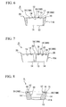
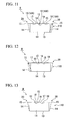
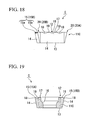
- the inserts A shown in FIG. 4 through FIG. 8 , the inserts B shown in FIG. 9 through FIG. 13 , and the inserts C shown in FIG. 14 through FIG. 19 are removably mounted.
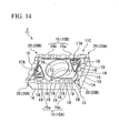
- the inserts C shown in FIG. 14 through FIG. 19 correspond to the roughing insert of an embodiment of the present invention.
- the other inserts A and B are also roughing inserts having a waveform cutting edge.
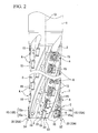
- the roughing end mill of the present embodiment has an end mill body 1 which is formed from steel or the like with a substantially circular column-shaped outer configuration centered on an axis O.
- a plurality (four in the present embodiment) of spiral-shaped chip removal grooves 2 are formed equidistantly in the circumferential direction on an outer circumference of a distal end portion of the end mill body 1. These chip removal grooves 2 are twisted around the axis O moving from the distal end of the end mill body 1 towards the rear end side in the direction of the axis O (i.e., in an upwards direction in FIG. 2 ) towards the rear in a rotation direction T in which the end mill body 1 rotates during a cutting process.
- a plurality of insert mounting seats 3 which are placed apart from each other in the direction of the axis O are formed in a wall surface of each chip removal groove 2 which faces in the aforementioned rotation direction T.
- the aforementioned inserts A through C are removably mounted by means of clamping screws 4 in these insert mounting seats 3.
- inserts A through C are provided with square plate-shaped insert bodies 11A, 11B, and 11C which are formed from a hard material such as cemented carbide.
- a rake face 12 One of two square surfaces which face in the thickness direction of the flat plate formed by each of these insert bodies 11A, 11B, and 11C is formed as a rake face 12, while the other surface is a flat surface which is perpendicular to the aforementioned thickness direction and serves as a seating surface 13 for mounting on an insert mounting seat 3.
- Four circumferential surfaces which are placed around the periphery of the square surfaces each form flank faces 14.
- Cutting edges 15 are formed in intersecting ridge portions between the four flank faces 14 and the aforementioned rake face 12.
- each flank face 14 is formed as a positive flank face which gradually recedes as it moves from the rake face 12 towards the seating surface 13 side.
- the inserts A through C are thus formed as positive inserts which have a relief angle formed in the cutting edges 15.
- a mounting hole 16 through which the aforementioned clamping screw 4 is inserted is formed extending in the thickness direction from the center of the rake face 12 to the seating surface 13.
- the periphery of the aperture portion of the mounting hole 16 in the rake face 12 is formed as a boss surface 17 which is a flat surface which is perpendicular to the thickness direction and which protrudes in the thickness direction beyond the cutting edges 15.
- the boss surface 17 has substantially the same outer configuration as the rake face 12 of each of the inserts A through C, but is formed at a smaller size than the rake face 12.
- a plurality of groove portions (i.e., recessed portions) 18 and raised portions 19 which reach as far as the flank faces 14 are formed altematingly along the cutting edges 15 in the rake face 12 on the outer side of the boss surface 17.
- the cutting edges 15 are formed as waveform cutting edges which undulate in the thickness direction and extend along the intersecting ridge line portion facing in a circumferential direction around the rake face 12.
- the flank faces 14 are formed as positive flank faces, the cutting edges 15 are formed as waveform cutting edges which also undulate inwards and outwards relative to the rake face 12 when seen in plan view facing the rake face 12 along the aforementioned center line.
- the cutting edges 15 at each corner portion 20 of the square rake faces 12 of the respective inserts A through C are formed so as to extend along a single plane which is perpendicular to the thickness direction.
- the waveform cutting edges are formed by alternating the groove portions 18 and the raised portions 19 in this order starting from these corner portions 20, and the apex point of each raised portion 19 is located on the level of the aforementioned single plane.
- the waveform cutting edges formed by these groove portions 18 and raised portions 19 have a shape made up of broadly circular arc-shaped concave curves and convex curves which are smoothly continuous.
- groove portions 18, the raised portions 19, and the corner portions 20 are inclined where their cross sections intersect with the flank face 14 so as to slope slightly downwards in the thickness direction as they move away from the cutting edges 15 towards the inner side of the rake face 12.
- a wall surface around the boss surface 17 which intersects with the groove portions 18, raised portions 19, and corner portions 20 is formed as a sloping surface which rises upwards in the thickness direction at a steeper gradient than the slope of the groove portions 18, raised portions 19, and corner portions 20 as it moves inwards until it reaches the boss surface 17.
- the above described insert A has a substantially square, planar shape and is formed so as to be rotationally symmetrical every 90° around the center line of the mounting hole 16 which forms a reference line for the insert body 11A.
- the cutting edges 15 of the insert A are made up of three groove portions 18 and two raised portions 19 being placed altematingly between adjacent corner portions 20.
- the cutting edges 15 present a waveform shape having a uniform wavelength and, particularly in the present embodiment, the intervals between the bottommost portions of the groove portions 18 and the topmost portions of the raised portions 19 are mutually equivalent.
- the groove depth in the thickness direction of the groove portions 18 on the two corner portion 20 sides are mutually the same, and form shallow groove portions 18A which have a shallow groove depth, while the groove portion 18 in the center forms a deep groove portion 18B whose groove depth is deeper than that of the shallow groove portions 18A.
- the shallow groove portions 18A and 18B are formed alternatingly, and have different wave amplitudes.
- the cutting edges 15 of this insert A form chamfered corner edges in the corner portions 20 where the corners of the aforementioned square have been rectilinearly chamfered when seen in plan view.
- the inserts B and C are formed as substantially rhomboid flat plates in which the respective corner portions 20 of the rake face 12 are either slightly acute angles or slightly obtuse angles.
- the long sides of the parallelogram i.e., the sides extending in a vertical direction in FIG. 10
- the short sides i.e., the sides extending in a horizontal direction in FIG. 10
- the length of the short sides is the same as in the inserts B while, as is shown in FIG. 15 , the long sides are longer than those in the inserts B.
- the gaps between the long sides in both the inserts B and C are the same as each other, and are also the same as the gaps between opposing sides in the inserts A. Furthermore, the respective corner angles in the acute angle corner portions 20A and the obtuse angle corner portions 20B of the corner portions 20 are the same as each other in the inserts B and C. Accordingly, the inserts C have an external shape which is obtained by extending the inserts B in the direction of the long sides thereof, and are formed by long-edged inserts from the inserts which are mounted at the tip of the distal end of the end mill body 1, while in contrast, the inserts B are formed by short-edged inserts.
- the short-edged inserts B are formed so as to be rotationally symmetrical every 180° around the center line of the mounting hole 16 (i.e., so as to have line symmetry) which forms a reference line for the insert body 11B.
- three groove portions 18 and two raised portions 19 are formed alternatingly between adjacent corner portions 20 on the aforementioned long sides thereof so that waveform cutting edges 15 having a uniform wavelength are formed.
- the groove portions 18 on the two corner portion 20 sides form shallow groove portions 18A, while the groove portion 18 in the center forms a deep groove portion 18B.
- waveform cutting edges 15 having the same wavelength and amplitude as the cutting edges 15 formed on the short sides of the inserts B which are provided with three groove portions 18 alternating with two raised portions 19 are formed on the short sides thereof.
- the groove portions 18 on both ends are formed adjacent to the two corner portions 20, so that the phases of the waveforms formed by the cutting edges 15 when the short sides of the inserts B and C are overlapped with each other are mutually offset by half a wavelength.
- the groove portions 18, raised portions 19, and cutting edges 15 which are formed on the pair of short sides of this insert C are rotationally symmetrical in a 180° rotation around the center line of the mounting hole 16 which forms a reference line for the insert body 11C of the relevant insert C.
- the groove depth of the groove portions 18 is deeper and the width of the groove portions 18 and raised portions 19 is also greater.
- the obtuse angle corner cutting edge portions 15b have a smaller wavelength and amplitude than the acute angle corner cutting edge portions 15a, and in the insert C of the present embodiment each one is half as large.
- the acute angle corner cutting edge portions 15a occupy a greater length of the cutting edges 15 formed on the long sides than do the obtuse angle corner cutting edge portions 15b, and the length from the distal end of the acute angle corner portion 20A of the acute angle corner cutting edge portion 15a to the apex portion of the center raised portion 19 is equal to the length from the distal end of the acute angle corner portion 20A to the boundary thereof with the obtuse angle corner portion 20B of the cutting edge 15 formed on the long side of the above described inserts B.
- the depths of the groove portions 18 are the same, and the amplitude of the waveforms formed by these cutting edges 15 as well as the wavelength thereof are uniform.
- the pair of long sides of the parallelogram formed by the rake face are formed non-symmetrically such that, when the insert body 11C is rotated 180° around the center line of the mounting hole 16 which forms the aforementioned reference line, the waveforms of one or more portions of the cutting edges 15 formed on these long sides do not match.
- the obtuse angle corner cutting edge portions 15b which form the above described portion of the waveform cutting edges 15 formed on the long sides are formed asymmetrically from each other, while the acute angle corner cutting edge portions 15a which form the remaining portion are formed symmetrically around the center line so as to match each other when the insert body 11C is rotated 180° around the center line.
- the wavelength and amplitude of the waveforms of the obtuse angle corner cutting edge portions 15b of the waveform cutting edges 15 formed on the pair of long sides are formed equal to each other and, as is described above, as half those of the acute angle corner cutting edge portions 15a.
- the insert body 11C is rotated 180° around the center line so as to superimpose these obtuse angle corner cutting edge portions 15b, they are asymmetrical due to the phases of the waveforms thereof being offset. In the present embodiment, this phase offset amount is equal to half the wavelength of the obtuse angle corner cutting edge portion 15b.
- the groove portions 18 of the obtuse angle corner cutting edge portions 15b are formed so as to be continuous with the apex portion of the center raised portion 19 of this cutting edge 15A, and a space is opened up between the groove portion 18 on the obtuse angle corner portion 20B side of this obtuse angle corner cutting edge portion 15b and this obtuse angle corner portion 20B, and a short rectilinear portion is formed extending from the obtuse angle corner portion 20B along the aforementioned single plane.
- the groove portions 18 of the obtuse angle corner cutting edge portions 15b are formed so as to be continuous on the obtuse angle corner portion 20B side of this cutting edge 15B with this obtuse angle corner portion 20B, and a short rectilinear portion is formed on the apex portion of the center raised portion 19 of the cutting edge 15B extending along the aforementioned single plane, and the groove portion 18 on the obtuse angle corner cutting edge portion 15b side of this center raised portion 19 is formed with a gap between itself and the acute angle corner cutting edge portion 15a.
- different characters 17A such as, for example, [A] and [B] are provided respectively inside recessed locations formed in inside portions of the pair of acute angle corner portions 20A in the boss surface 17 of the insert C of the present embodiment so as to correspond to the providing of the waveform cutting edges 15A and 15B which are asymmetrical and have different phases in certain portions.
- these inserts A through C which include the roughing insert C of the present embodiment are arranged such that two each of the inserts B and C which each have the same shape and size are mounted alternatingly in the circumferential direction in four insert mounting seats 3 which are formed at the tip of the distal end of the respective chip removal grooves 2 of the end mill body 1, and such that inserts A which also each have the same shape and size as each other are mounted in the remaining insert mounting seats 3 thereby forming an insert row in each of the chip removal grooves 2.
- two insert rows of the inserts B and A and two insert rows of the inserts C and A respectively in that sequence from the distal end side are arranged alternatingly in the circumferential direction. Note that a plurality of the inserts A are provided in each of these insert rows.
- the insert mounting seats 3 at the tip of the distal end where the inserts B and C are mounted are formed as recessed portions which are open to the distal end surface and outer circumferential surface of the end mill body 1 by sufficiently hollowing out the wall surface of the chip removal groove 2 which faces in the aforementioned rotation direction T.
- the insert mounting seats 3 are provided with a bottom surface which faces in the rotation direction T, and with a wall surface which faces towards the distal end side of the end mill body 1 and a wall surface which faces towards the outer circumferential side of the end mill body 1.
- inserts B and C are then fastened in this type of insert mounting seat 3 with the rake faces 12 thereof facing in the aforementioned rotation direction T and the seating surfaces 13 thereof being adhered to the aforementioned bottom surface, and with one acute angle corner portion 20A being positioned at the outer circumferential side of the distal end of the end mill body 1, and the cutting edge 15 which is formed on the above described long side which intersects this acute angle corner portion 20A protruding as an outer circumferential edge on the outer circumferential side of the end mill body 1 and the cutting edge 15 which is formed on the above described short side protruding as a bottom edge towards the distal end side of the end mill body 1.
- flank faces 14 which intersect the acute angle corner portion 20A on the opposite side from this are then seated by being butted against the aforementioned wall surfaces, and the clamp screw 4 which is inserted through the mounting hole 16 is then screwed into a threaded hole formed in the bottom surface thereby completing the fastening.
- the inserts B and C which are mounted in this manner are positioned such that the positions in the O axial direction of the acute angle corner portions 20A thereof which are facing towards the outer circumferential side at the distal end of the end mill body 1, as well as the radius from the axis O of each one are equal to each other, and such that the cutting edges 15 which form the above described outer circumferential edge extend roughly in parallel with the axis O as seen from the rotation direction T side. Accordingly, the rotation trajectory around this axis O of these cutting edges 15 which form the above described outer circumferential edge forms a substantially circular cylinder shape centered on the axis O with the cutting edges 15 of the inserts B overlapping with the acute angle corner cutting edge portions 15a of the cutting edges 15 of the inserts C.
- the cutting edges 15 which form the bottom edges facing towards the distal end side are slightly tilted at the same angle as each other in the inserts B and C so as to move towards the rear end side of the end mill body 1 as they move towards the inner circumferential side, and the rotation trajectories thereof around the axis O also overlap with each other.
- the insert mounting seats 3 where the inserts A of the present embodiment are mounted are formed as recessed portions which are open to the outer circumferential surface of the end mill body 1 by sufficiently hollowing out the aforementioned wall surface of the chip removal groove 2.
- the insert mounting seats 3 are provided with a bottom surface which faces in the rotation direction T, and with three wall surfaces, namely, a wall surface which faces towards the distal end side of the end mill body 1, a wall surface which faces towards the outer circumferential side, and a wall surface which faces towards the rear end side of the end mill body 1.
- inserts A are fastened in this type of insert mounting seat 3 by the clamp screws 4 in the same way as the inserts B and C with the rake faces 12 thereof facing in the aforementioned rotation direction T, and the seating surfaces 13 thereof being adhered to the aforementioned bottom surfaces, and with one cutting edge 15 protruding on the outer circumferential side as an outer circumferential edge, and with the flank faces 14 which are continuous with the remaining three cutting edges 15 then seated by being butted against the respective wall surfaces.
- the inserts A which are mounted in this manner are positioned such that the one cutting edge 15 thereof which forms the outer circumferential edge extends roughly in parallel with the axis O as seen from the rotation direction T side, and such that the rotation trajectory thereof around this axis O forms a substantially circular cylinder shape centered on the axis O, with the radius thereof being equal to that of the rotation trajectories of the cutting edges 15 which form the outer circumferential edges of the inserts B and C. Note that, as is shown in FIG.
- inserts A are placed such that, as is shown in FIG. 3 , insert rows which are adjacent to each other in the circumferential direction are offset from each other in the O axial direction. Furthermore, one insert A of one insert row and an insert A of another insert row which is offset therefrom in the O axial direction are positioned such that the waveforms of the waveform cutting edges which are formed by the cutting edges 15 which form the outer circumferential edges of these inserts have phases which are continuous in a rotation trajectory around the axis O.
- One waveform cutting edge row is formed by the waveform cutting edges 15 whose waveforms are continuous in this manner, and a plurality of these waveform cutting edge rows having different phases are formed on the outer circumference of the end mill body 1.
- the above described inserts A are positioned such that in each insert row a gap of less than one insert A is formed in the O axial direction, and in insert rows which are adjacent to each other in the circumferential direction, the inserts A of one of these adjacent inserts rows are positioned in the gap portions in the O axial direction between the inserts A of the other of these adjacent insert rows.
- the insert rows shown in FIG. 3 are taken from the left side as first through fourth insert rows S1 through S4
- three inserts A are mounted with a gap between each one on the rearward side in the O axial direction of an insert B which is mounted at the tip of the distal end of the first insert row S1.
- inserts A11, A12, and A13 are taken as inserts A11, A12, and A13 in this order form the distal end side.
- two inserts A21 and A22 are mounted with a gap between each one on the rearward side in the O axial direction of an insert C which is mounted at the tip of the distal end of the second insert row S2
- three inserts A31, A32 and A33 are mounted with a gap between each one on the rearward side in the O axial direction of an insert B which is mounted at the tip of the distal end of the third insert row S3
- two inserts A41 and A42 are mounted with a gap between each one on the rearward side in the O axial direction of an insert C which is mounted at the tip of the distal end of the fourth insert row S4.
- These inserts are positioned so as to be offset from each other in the O axial direction in insert rows which are adjacent to each other in the circumferential direction.
- the waveform cutting edges 15 which face towards the outer circumferential side of the distal end insert A 11 from among the inserts A in the first insert row S 1 are placed such that the positions in the O axial direction of the distal end and rear end thereof match, in this sequence moving rearwards, those of the respective waveform cutting edges 15 of the distal end insert A41 from among the inserts A of the fourth insert row S4, the second insert A32 from the distal end from among the inserts A of the third insert row S3, the second insert A42 from among the inserts A of the fourth insert row S4, and the third insert A33 from among the inserts A of the third insert row S3, and are positioned so as to be continuous on a rotation trajectory around the axis O, so that a first waveform cutting edge row is created by these waveform cutting edges 15.
- the respective waveform cutting edges 15 of the inserts A other than the above inserts A namely, of the distal end insert A31 of the third insert row S3, the distal end insert A21 of the second insert row S2, the second insert A12 from the distal end of the first insert row S1, the second insert A22 of the second insert row S 12, and the third insert A13 of the first insert row S 1 are also continuous in the same way in this sequence on a rotation trajectory around the axis O so as to create a second waveform cutting edge row.
- these first and second waveform cutting edge rows are positioned such that the phases thereof are offset by half the wavelength of the waveform of each waveform cutting edge 15. Accordingly, in the roughing end mill of the present embodiment, a structure is employed in which two waveform cutting edge rows having mutually different phases are formed on the outer circumference of the end mill body 1.
- the inserts A11 and A31 at the distal end of the first and third insert rows S 1 and S3 which are positioned behind the inserts B which have shorter long sides are positioned so as to be offset by approximately one insert A on the distal end side of the inserts A21 and A41 at the distal end of the second and fourth insert rows S2 and S4 which are positioned behind the inserts C which have longer long sides.
- the insert A31 which forms part of the second waveform cutting edge row is positioned half the wavelength of a waveform cutting edge 15 on the distal end side of the insert A 11 which forms part of the first waveform cutting edge row.
- any one insert A of these inserts A is positioned so as to form a particular waveform cutting edge row with at least one insert A of another insert row which is adjacent in the circumferential direction to the insert row where this any one insert A is located.
- the rear end of the waveform cutting edge 15 of the insert A11 of the first insert row S 1 is continuous with the insert A41 of the fourth insert row S4 to which it is adjacent on the side of the rotation direction T, and both ends of the waveform cutting edges 15 of the inserts A41 and A42 of the fourth insert row S4 are continuous with the inserts A32 and A33 of the third insert row S3 to which they are adjacent in the rotation direction T, so as to form the first waveform cutting edge row.
- the waveform cutting edge 15 of the insert A31 at the distal end of the third insert row S3 is continuous with the insert A21 of the second insert row S2 to which it is adjacent on the side of the rotation direction T in the circumferential direction, and the inserts A21 and A22 of the second insert row S2 are continuous with the inserts A12 and A13 of the first insert row S1 to which they are adjacent in the rotation direction T.
- the insert A11 at the distal end thereof forms part of the first waveform cutting edge row, while the other inserts A12 and A13 form part of the second waveform cutting edge row.
- the insert A31 at the distal end of the third insert row S3 forms part of the second waveform cutting edge row, while the other inserts A32 and A33 form part of the first waveform cutting edge row.
- the gaps in the O axial direction between the inserts A11 and A12 and between the inserts A12 and A13 in the first insert row S 1, and also the gaps in the O axial direction between the inserts A31 and A32 and between the inserts A32 and A33 in the third insert row S3, namely, the gaps between the insert mounting seats 3 are all made different sizes.
- the waveform cutting edges 15 thereof which face towards the outer circumferential side are positioned such that sides thereof where the phases of the obtuse angle corner cutting edge portions 15b are different from each other are made to face towards the outer circumferential side.
- these inserts C are mounted such that, of the waveform cutting edges 15A and 15B which are positioned rotationally symmetrically to each other 180° around the center line, the two obtuse angle corner cutting edge portions 15b which form a mutually asymmetrical portion thereof are made to overlap on the rotation trajectory around the O axis.
- the insert C at the tip of the distal end of the second insert row S2 is mounted such that the above described waveform cutting edge 15A faces towards the outer circumferential side
- the insert C at the tip of the distal end of the fourth insert row S4 is mounted such that the above described waveform cutting edge 15B faces towards the outer circumferential side.
- the obtuse angle corner cutting edge portions 15b of the respective waveform cutting edge portions 15A and 15B are also placed such that the phases thereof are offset by half the wavelength of the waveform of each obtuse angle corner cutting edge portion 15b. Accordingly, two waveform cutting edges having mutually different phases are formed on the outer circumference of the end mill body 1.
- the inserts A11 and A31 of the first and third insert rows S1 and S3 which are positioned on the distal end side are positioned such that, on the rotation trajectory, the waveform cutting edges 15 thereof are either continuous with or overlap the waveform cutting edges 15A and 15B of these inserts C of the present embodiment at the tip of the distal ends of the second and fourth insert rows S2 and S4.
- the insert A 11 of the first insert row S 1 is positioned such that the distal end of the waveform cutting edge 15 thereof and the rear end of the waveform cutting edge 15B (i.e., the rear end of the obtuse angle corner cutting edge portion 15b) of the insert C of the fourth insert row S4 which is located on the rotation direction T side have mutually matching phases on the rotation trajectory.
- the insert A31 of the third insert row S31 is positioned such that the distal end of the waveform cutting edge 15 thereof and the apex portion of the raised portion 19 on the obtuse angle corner portion 20b side of the obtuse angle corner cutting edge portion 15b of the insert C at the tip of the distal end of the fourth insert row S4 match each other on the rotation trajectory, and this insert C and the insert C at the tip of the distal end of the fourth insert row S4 are positioned such that the waveform cutting edges 15 overlap each other.
- the inserts A through C which make up the plurality of insert rows S 1 through S4 are positioned apart from each other in the O axial direction, and, of these, a portion of the inserts A are positioned so as to be offset from each other in the O axial direction in insert rows S 1 through S4 which are adjacent in the circumferential direction.
- the waveform cutting edges 15 thereof make up a waveform cutting edge row in which the phases of the respective waveform cutting edges 15 are continuous along a rotation trajectory around the axis, and a plurality of (two in the present embodiment) these waveform cutting edge rows having mutually different phases are formed on the outer circumference of the end mill body 1, it is possible to obtain a smooth processing surface by, for example, using the raised portions of a second waveform cutting edge row to cut the raised portions of an opposite-phase waveform cross section which have been formed on a work processing surface by a first waveform cutting edge row.
- the result of this is that, in spite of the processing being only roughing, namely, rough processing, it is possible to perform comparatively smooth, high quality cutting of a processing surface.
- the respective inserts B and C are mounted at the tips of the distal end of the respective insert rows S1 through S4, and these inserts B and C are positioned such that the rotation trajectories around the axis O of the waveform cutting edges 15 thereof which are facing towards the outer circumferential side overlap due to the phases of the inserts B and the acute angle corner cutting edge portions 15a of the inserts C being offset by half a wavelength, and such that the rotation trajectories of the cutting edges 15 thereof which form bottom edges also overlap.
- these cutting edges 15 which form bottom edges also have a waveform edge shape, and the phases thereof are also mutually offset by half a wavelength in the inserts B and C.
- the two waveform cutting edges 15A and 15B which form outer circumferential edges are longer than in an insert B, and the two obtuse angle corner cutting edge portions 15b of a portion thereof perform cutting between the inserts A and B on the distal end side of the first and third insert rows S1 and S3, as is described above
- the two waveform cutting edges 15A and 15B which are formed at positions which are rotationally symmetrical every predetermined angle (180°) around the center line which forms a reference line of the insert body 11C are formed asymmetrically so as to not match each other when the two obtuse angle corner cutting edge portions 15b which form a portion of the waveform cutting edges 15A and 15B cause the insert body 11C to rotate by the aforementioned predetermined angle.
- this insert C is formed so as to be rotationally symmetrical 180° around the center line in the same way, for example, as the insert B at the tip of the distal end of the same end mill body 1, then two types of inserts C become necessary in order to prevent the rotation trajectories of the waveform cutting edges 15 of the inserts C from matching in the portions between the insert B and the inserts A11 and A31 of the same insert rows S1 and S3. Accordingly, two types of metal molds are also required to mold a green compact from cemented carbide raw powder in order to manufacture these inserts C so that there is also an increase in manufacturing costs. Moreover, if the number of insert types increases, the control thereof also becomes more complex which requires considerable labor.
- the insert C having the above described structure even if the wrong waveform cutting edge 15A or 15B to be used as the outer circumferential edge is placed in either one of the two inserts C, and the roughing end mill becomes mounted such that the two obtuse angle corner cutting edge portions 15b which form a portion thereof trace the same rotation trajectory, because these obtuse angle corner cutting edge portions 15b have a waveform with a smaller wavelength than the acute angle corner cutting edge portions 15a which are the remaining portions of the waveform cutting edges 15A and 15B in the same insert C, and a smaller wavelength than the waveform cutting edge 15 of the insert B, the interval (i.e., the pitch) between undulations which is transferred onto a processing surface is smaller than the intervals between undulations formed by the waveform cutting edges 15 of both the acute angle corner cutting edge portions 15a and the cutting edges 15 of the inserts B. Accordingly, it is possible to avoid the formation of a processing surface having a conspicuously large level of roughness.
- the wavelengths of the waveforms formed by the obtuse angle corner cutting edge portions 15b are half those of the acute angle corner cutting edge portions 15a, even if, by some chance, the rotation trajectories of two obtuse angle corner cutting edge portions 15b were to coincide in two inserts C, because the interval between undulations formed on the processing surface is also half the undulation of one wave of the acute angle corner cutting edge portions 15a and the cutting edges 15 of the inserts B, and the acute angle corner cutting edge portions 15a of the inserts C and the intervals between undulations formed on the processing surface by the cutting edge 15 of the inserts B are substantially equivalent, it is possible to more reliably prevent any deterioration in surface roughness. Accordingly, according to the roughing insert C having the above described structure, even if a mounting error occurs, it is not necessary to set a substantial allowance in finishing processing in subsequent steps, and it becomes possible to achieve efficient cutting processing.
- the amplitude as well is smaller than, namely, is half that of the acute angle corner cutting edge portions 15a which are the remaining portions. Accordingly, if a mounting error occurs, the depth of the recessed portions formed in the processing surface by these obtuse angle corner cutting edge portions 15b as well is shallower, namely, is half the depth of the recessed portions formed by the acute angle corner cutting edge portions 15a and the cutting edges 15 of the inserts B.
- the roughness of the processing surface can be restricted to substantially the same level of roughness as that obtained when the rotation trajectories of the acute angle corner cutting edge portions 15a in two inserts C are offset by half a phase of the wavelength thereof, and it becomes possible to more reliably suppress any deterioration thereof.
- the obtuse angle corner cutting edge portions 15b which are a portion of a waveform cutting edge 15 whose wavelength and amplitude have been made smaller in the manner described above, are formed at rotationally symmetrical positions of one insert body 11C which is formed so as to be rotationally symmetrical around the center line thereof.
- These obtuse angle corner cutting edge portions 15b are formed asymmetrically so as not to coincide with each other when the insert body 11C is rotated by a predetermined angle around the center line thereof.
- these two inserts C are mounted such that the waveform cutting edges 15A and 15B which include the mutually asymmetrical obtuse angle corner cutting edge portions 15b are each facing towards an outer circumferential side.
- the obtuse angle corner cutting edge portions 15b which form a portion of the two waveform cutting edges 15A and 15B which are positioned rotationally symmetrically, such that they are asymmetrical and do not match each other when the insert body 11C is rotated around the reference line (i.e., the above described center line) by a predetermined angle, it is sufficient if, for example, they are formed having waveforms with different wavelengths and amplitudes, and are formed such that when they are made to overlap each other their mutual waveforms counteract each other.
- the cutting amount in the two obtuse angle corner cutting edge portions 15b of each insert C can be made substantially equal, and it is possible to achieve uniform cutting resistance between the inserts C. This promotes stable cutting, and achieves uniform wear between the obtuse angle corner cutting edge portions 15b, and also makes it possible to coincide the timings of switching corners and replacing an insert C.
- the waveforms of these obtuse angle corner cutting edge portions 15b are formed such that the wavelengths and amplitudes thereof are the same and such that the phases thereof are offset by half a wavelength when the insert body 11C is rotated 180° around the center line, and the inserts C are mounted such that these obtuse angle corner cutting edge portions 15b having mutually different phases are positioned alternatingly in the circumferential direction of the end mill body 1.
- the raised portions in a processing surface left behind after cutting by the groove portions 18 of the waveform of an obtuse angle corner cutting edge portion 15b of one insert C can be cut away by the raised portions 19 of the waveform of the obtuse angle corner cutting edge portion 15b of the other insert C which follows on behind the one insert C as a result of the rotation of the end mill body 1. Accordingly, it is possible to form a smooth processing surface without needlessly increasing the number of insert types.
- the waveform cutting edges 15 of the inserts B which have placed alternatingly between these inserts C so as to overlap each other are formed, for example, having the same wavelength but having phases which are mutually offset by half a wavelength such that they do not coincide with the acute angle corner cutting edge portions 15a on a rotation trajectory, then according to the present embodiment, it is possible to perform cutting using a total of four of the inserts B and C which are provided at the distal end of the end mill body 1 as is described above. It is also possible to reduce the load which is applied to each one of the inserts B and C and achieve an improvement in the quality of the processing surface.
- the present invention relates to a roughing insert which includes: an insert body; and a waveform cutting edge which is formed on an intersecting ridge line portion between a rake face and a flank face of the insert body, and which undulates along this intersecting ridge line portion, wherein the waveform cutting edges are formed such that a portion thereof has a smaller wavelength than the remaining portion thereof.
- a waveform cutting edge which is formed on an intersecting ridge line portion between a rake face and a flank face of the insert body, and which undulates along this intersecting ridge line portion, wherein the waveform cutting edges are formed such that a portion thereof has a smaller wavelength than the remaining portion thereof.
Claims (10)
- Plaquette d'ébauche (C) comprenant :un corps de plaquette (11C) ; etdes arêtes de coupe en forme de vagues (15) qui sont formées en alternance de parties de rainures (18) et de parties surélevées (19) sur une partie de ligne de crête d'intersection entre une face de coupe (12) et une face de flanc (14) du corps de plaquette, et qui ondulent le long de cette partie de ligne de crête d'intersection, caractérisée en ce que :chacune des arêtes de coupe en forme de vagues (15), qui sont formées sur les côtés longs d'un parallélogramme formé par la face de coupe, présente des parties d'arête de coupe de coin à angle aigu (15a) et des parties d'arête de coupe de coin à angle obtus (15b),les parties d'arête de coupe de coin à angle aigu (15a) sont situées entre une partie de sommet d'une partie centrale surélevée (19) et une partie de coin à angle aigu (20A) du parallélogramme formé par la face de coupe,les parties d'arête de coupe de coin à angle obtus (15b) sont situées entre la partie de sommet de la partie centrale surélevée (19) et une partie de coin à angle obtus (20B) du parallélogramme formé par la face de coupe, etles parties d'arête de coupe de coin à angle obtus (15b) présentent une longueur d'onde inférieure à celle des parties d'arête de coupe de coin à angle aigu (15a).
- Plaquette d'ébauche (C) selon la revendication 1, dans laquelle
chacune des arêtes de coupe en forme de vagues (15) est formée de sorte que la longueur d'onde des parties d'arête de coupe de coin à angle obtus (15b) soit la moitié de la longueur d'onde des parties d'arête de coupe de coin à angle aigu (15a). - Plaquette d'ébauche (C) selon la revendication 1, dans laquelle
chacune des arêtes de coupe en forme de vagues est formée de sorte que les parties d'arête de coupe de coin à angle obtus (15b) présentent une amplitude inférieure à celle des parties d'arête de coupe de coin à angle aigu (15a). - Plaquette d'ébauche (C) selon la revendication 3, dans laquelle
chacune des arêtes de coupe en forme de vagues est formée de sorte que l'amplitude des parties d'arête de coupe de coin à angle obtus (15b) soit la moitié de l'amplitude des parties d'arête de coupe de coin à angle aigu (15a). - Plaquette d'ébauche (C) selon la revendication 1, dans laquelle
les arêtes de coupe en forme de vagues (15A, 15B) sont formées sur le corps de plaquette (11C) respectivement à des positions qui sont symétriques en rotation à des intervalles angulaires prédéterminés autour d'une ligne de référence du corps de plaquette (11C), et ces arêtes de coupe en forme de vagues (15A, 15B) qui sont positionnées de façon symétrique en rotation l'une à l'autre sont formées de sorte que, lorsque le corps de plaquette (11C) est tourné selon l'angle prédéterminé autour de la ligne de référence, les parties d'arête de coupe de coin à angle obtus (15b) des arêtes de coupe en forme de vagues (15A, 15B) ne se correspondent pas et soient mutuellement asymétriques. - Plaquette d'ébauche (C) selon la revendication 5, dans laquelle
les parties d'arête de coupe de coin à angle obtus (15b) des arêtes de coupe en forme de vagues positionnées de façon symétrique en rotation (15A, 15B) deviennent asymétriques lorsque les corps de plaquettes (11c) sont mis en rotation selon l'angle prédéterminé autour de la ligne de référence par décalage des phases de celles-ci tout en rendant la longueur d'onde et l'amplitude de celles-ci mutuellement égales. - Plaquette d'ébauche (C) selon la revendication 6, dans laquelle
les phases sont décalées par la moitié de la longueur d'onde des parties d'arête de coupe de coin à angle obtus (15b) des arêtes de coupe en forme de vagues (15A, 15B). - Plaquette d'ébauche (C) selon la revendication 5, dans laquelle
les arêtes de coupe en forme de vagues (15A, 15B) qui sont positionnées de façon symétrique en rotation l'une à l'autre sont formées de sorte que, lorsque les corps de plaquettes (11C) sont mis en rotation selon l'angle prédéterminé autour de la ligne de référence, les parties d'arête de coupe de coin à angle aigu (15a) se correspondent et soient mutuellement symétriques. - Fraise d'ébauche en bout comprenant :un corps de fraise en bout (1) ; etune pluralité de plaquettes d'ébauche (A, B, C) qui sont montées de façon amovible séparément les unes des autres dans la direction circonférentielle sur une circonférence extérieure du corps de fraise en bout (1) qui tourne autour d'un axe (10), oùau moins deux parmi les plaquettes d'ébauche selon la revendication 1 sont montées de sorte que les parties d'arête de coupe de coin à angle obtus (15b) des arêtes de coupe en forme de vagues (15) soient réalisées afin de se chevaucher l'une l'autre dans la direction axiale.
- Fraise d'ébauche en bout selon la revendication 9, dans laquelle
les parties d'arête de coupe de coin à angle obtus (15b) des arêtes de coupe en forme de vagues (15) sont réalisées pour se chevaucher l'une l'autre sans que les trajectoires de rotation de celles-ci autour de l'axe (o) coïncident.
Applications Claiming Priority (3)
| Application Number | Priority Date | Filing Date | Title |
|---|---|---|---|
| JP2006248174A JP5023628B2 (ja) | 2006-09-13 | 2006-09-13 | ラフィングエンドミル |
| JP2006295907A JP5050488B2 (ja) | 2006-10-31 | 2006-10-31 | ラフィング用インサートおよびラフィングエンドミル |
| PCT/JP2007/067851 WO2008032788A1 (fr) | 2006-09-13 | 2007-09-13 | Plaquette de dégrossissage, et fraise en bout de dégrossissage |
Publications (3)
| Publication Number | Publication Date |
|---|---|
| EP2060353A1 EP2060353A1 (fr) | 2009-05-20 |
| EP2060353A4 EP2060353A4 (fr) | 2010-12-22 |
| EP2060353B1 true EP2060353B1 (fr) | 2012-12-19 |
Family
ID=39183842
Family Applications (1)
| Application Number | Title | Priority Date | Filing Date |
|---|---|---|---|
| EP07807258A Active EP2060353B1 (fr) | 2006-09-13 | 2007-09-13 | Plaquette de dégrossissage, et fraise en bout de dégrossissage |
Country Status (4)
| Country | Link |
|---|---|
| US (2) | US7993082B2 (fr) |
| EP (1) | EP2060353B1 (fr) |
| KR (1) | KR101369580B1 (fr) |
| WO (1) | WO2008032788A1 (fr) |
Families Citing this family (25)
| Publication number | Priority date | Publication date | Assignee | Title |
|---|---|---|---|---|
| JP5023628B2 (ja) * | 2006-09-13 | 2012-09-12 | 三菱マテリアル株式会社 | ラフィングエンドミル |
| WO2008032788A1 (fr) * | 2006-09-13 | 2008-03-20 | Mitsubishi Materials Corporation | Plaquette de dégrossissage, et fraise en bout de dégrossissage |
| WO2008032778A1 (fr) * | 2006-09-13 | 2008-03-20 | Mitsubishi Materials Corporation | Plaquette pour dégrossissage et fraise en bout de dégrossissage |
| DE102008025961A1 (de) * | 2008-05-30 | 2009-12-03 | Kennametal Inc. | Schaftfräser |
| WO2010110110A1 (fr) * | 2009-03-27 | 2010-09-30 | 京セラ株式会社 | Plaquette de coupe, outil de coupe et procédé de découpe d'un matériau à couper au moyen de l'outil de coupe |
| EP2633932B1 (fr) | 2010-10-27 | 2017-12-06 | Subaru Corporation | Plaquette de fraisage et outil de coupe rotatif du type à remplacement de pointe de fraisage |
| US8708008B2 (en) | 2010-11-03 | 2014-04-29 | Sandvik Intellectual Property Ab | Shaped carbide tips, carbide-tipped teeth, and tools with same |
| AT512452A1 (de) * | 2012-02-01 | 2013-08-15 | Boehlerit Gmbh & Co Kg | Schneidplatte |
| US9144845B1 (en) * | 2012-03-01 | 2015-09-29 | The Boeing Company | Cutting tools with textured surfaces |
| US9649692B2 (en) * | 2012-04-23 | 2017-05-16 | Sumitomo Electric Hardmetal Corp. | Sintered cubic boron nitride compact tool |
| CN106862600A (zh) | 2012-06-01 | 2017-06-20 | 株式会社日研工作所 | 端铣刀的柄部构造 |
| US9079257B2 (en) | 2013-01-28 | 2015-07-14 | Kennametal Inc. | Indexable cutting insert for machining composite materials |
| US9180533B2 (en) * | 2013-02-07 | 2015-11-10 | Kennametal Inc. | Round cutting insert with serrated topography |
| US10124423B2 (en) * | 2014-07-14 | 2018-11-13 | Tungaloy Corporation | Rotary cutting tool having adjacent cutting inserts with wave-shaped edges and overlapping rotational trajectories coinciding in phase |
| TWI508804B (zh) * | 2014-12-23 | 2015-11-21 | Hsin Tien Chang | Screw feed cutter |
| JP6587090B2 (ja) * | 2015-03-30 | 2019-10-09 | 国立大学法人名古屋大学 | 転削工具 |
| CN106271493B (zh) * | 2015-05-21 | 2018-10-19 | 中国科学院宁波材料技术与工程研究所 | 一种激光预制微织构辅助超声铣削工艺方法及加工系统 |
| US10348576B2 (en) * | 2016-04-29 | 2019-07-09 | Microsoft Technology Licensing, Llc | Modeling resiliency strategies for streaming queries |
| US10556278B2 (en) * | 2016-08-16 | 2020-02-11 | Kennametal Inc. | Tool body for a shell end mill and cutting tool |
| DE102016216464A1 (de) * | 2016-08-31 | 2018-03-01 | Gühring KG | Aufrauwerkzeug und verfahren zum aufrauen einer zylindrischen oberfläche |
| DE112017007563T5 (de) | 2017-08-09 | 2020-02-20 | Osg Corporation | Wendeschneidplattenwerkzeug |
| US11850670B2 (en) | 2020-04-24 | 2023-12-26 | Kennametal India Ltd. | Milling cutting inserts |
| CN114309682A (zh) | 2020-09-30 | 2022-04-12 | 肯纳金属公司 | 切削刀片 |
| US11806796B2 (en) * | 2021-03-15 | 2023-11-07 | Kennametal Inc. | Cutting insert and cutting tool comprising cutting insert |
| US11865629B2 (en) | 2021-11-04 | 2024-01-09 | Kennametal Inc. | Rotary cutting tool with high ramp angle capability |
Family Cites Families (66)
| Publication number | Priority date | Publication date | Assignee | Title |
|---|---|---|---|---|
| US1472960A (en) | 1922-10-28 | 1923-11-06 | O K Tool Co | Disk cutter having staggered series of side teeth |
| US1840852A (en) | 1927-03-03 | 1932-01-12 | Joseph G Schotthoefer | Cutting tool |
| GB1207782A (en) | 1968-02-23 | 1970-10-07 | Maydown Products Ltd | Milling and other rotary cutters |
| US3574251A (en) | 1969-02-19 | 1971-04-13 | Marcoloy Inc | Cutting tool |
| US3574911A (en) | 1969-12-17 | 1971-04-13 | Milling Specialties Inc | Cutter and inserts therefor |
| FR2183362A5 (fr) | 1972-05-04 | 1973-12-14 | Giraud Pierre | |
| IT990237B (it) | 1972-08-15 | 1975-06-20 | Malinchak P | Perfezionamento negli inserti ta glienti per macchine per la lavora zione di metalli |
| US3922766A (en) | 1972-08-15 | 1975-12-02 | Paul Malinchak | Inserts for metal cutters |
| US3875631A (en) | 1972-08-15 | 1975-04-08 | Paul Malinchak | Inserts for metal cutters |
| US4093392A (en) | 1975-04-10 | 1978-06-06 | The Valeron Corporation | Milling cutter |
| US4936719A (en) | 1976-08-24 | 1990-06-26 | Greenleaf Corporation | Cutter and indexable on edge inserts with aligned corners and staggered serrated edges |
| US4794665A (en) | 1976-08-24 | 1989-01-03 | Greenleaf Corporation | Rotary cutter with serrated edges and positive/negative axial rake |
| JPS5369892U (fr) * | 1976-11-16 | 1978-06-12 | ||
| JPS5369892A (en) | 1976-12-01 | 1978-06-21 | Nagasaki Shiyouyu Miso Kougiyo | Production of miso |
| US4140431A (en) | 1977-11-18 | 1979-02-20 | Kennametal Inc. | Cutting insert |
| US4182587A (en) | 1978-04-26 | 1980-01-08 | Ingersoll Maschinen Und Werkzeuge Gmbh | Milling cutter and indexable insert therefor |
| US4248553A (en) | 1978-09-29 | 1981-02-03 | Fansteel Inc. | Cutting insert configuration |
| US4215955A (en) | 1978-10-11 | 1980-08-05 | Trw Inc. | Cutting tool and insert for same |
| JPS5938977Y2 (ja) * | 1979-06-06 | 1984-10-30 | 住友電気工業株式会社 | 波形切刃を有するスロ−アウエイチツプ |
| JPS60186116A (ja) | 1984-03-05 | 1985-09-21 | Sony Corp | Pll回路 |
| GB2179281B (en) | 1985-08-21 | 1989-12-06 | Gen Electric | Cutting tool insert having cutting edges with recesses |
| JPS6334010A (ja) | 1986-07-30 | 1988-02-13 | Nachi Fujikoshi Corp | ラフイングエンドミル |
| US4844666A (en) | 1986-08-22 | 1989-07-04 | Izumo Industrial Co., Ltd. | Insert rotary cutting tool |
| CN87205072U (zh) | 1987-06-15 | 1988-04-13 | 四川工具厂 | 可转位硬质合金玉米棒铣刀 |
| US4812087A (en) | 1987-07-09 | 1989-03-14 | Gte Valenite Corporation | End mill cutting tool and indexable insert therefor |
| IL85606A (en) | 1988-03-02 | 1994-02-27 | Amram Dotany | Helical cutting tool |
| US5158401A (en) | 1988-03-21 | 1992-10-27 | Gte Valenite Corporation | Indexable insert for roughing and finishing |
| SE465959B (sv) | 1988-09-06 | 1991-11-25 | Sandvik Ab | Skaer foer spaanavskiljande bearbetning |
| US5437522A (en) | 1991-09-06 | 1995-08-01 | Iscar Ltd. | Milling cutter with overlapping edge insert |
| DE4141368A1 (de) | 1991-12-14 | 1993-06-17 | Krupp Widia Gmbh | Schneideinsatz |
| JP2894404B2 (ja) | 1992-08-25 | 1999-05-24 | 三菱電機株式会社 | パイプの接合具 |
| IL103115A (en) | 1992-09-09 | 1996-09-12 | Iscar Ltd | Milling placement |
| JPH07299636A (ja) | 1994-04-28 | 1995-11-14 | Kyocera Corp | フライス工具用スローアウェイチップ |
| DE4431796A1 (de) | 1994-05-02 | 1996-03-14 | Krupp Widia Gmbh | Fräswerkzeug |
| JPH081427A (ja) | 1994-06-15 | 1996-01-09 | Toshiba Tungaloy Co Ltd | ラフィングエンドミル |
| JPH081426A (ja) | 1994-06-15 | 1996-01-09 | Toshiba Tungaloy Co Ltd | ラフィングエンドミル |
| JP3376727B2 (ja) | 1994-11-11 | 2003-02-10 | 三菱マテリアル株式会社 | スローアウェイ式エンドミル |
| DE59507624D1 (de) * | 1994-11-19 | 2000-02-17 | Komet Stahlhalter Werkzeug | Schneidplatte zur spanabhebenden bearbeitung von werkstücken |
| US5562370A (en) * | 1995-03-27 | 1996-10-08 | Kennametal Inc. | Insert having sinusoidal undulations for ball nose end mill |
| JP3588170B2 (ja) | 1995-08-10 | 2004-11-10 | 日立ツール株式会社 | 3次元加工用エンドミル |
| IL119114A0 (en) | 1996-08-22 | 1996-11-14 | Iscar Ltd | Cutting insert |
| FR2765507A1 (fr) | 1997-07-07 | 1999-01-08 | Safety Fabrique De Carbure De | Fraise hemispherique et plaquette pour une telle fraise |
| US5944456A (en) * | 1997-12-04 | 1999-08-31 | Kennametal Inc. | Three dimensional mill and milling inserts |
| US5913644A (en) | 1998-04-20 | 1999-06-22 | Kennametal Inc. | Helical mill having multiple flutes with differing rake angles |
| SE516252C2 (sv) | 2000-04-28 | 2001-12-10 | Sandvik Ab | Fräsverktyg innefattande en roterbar kropp samt tangentiellt åtskilda skärorgan |
| US6976811B1 (en) | 2000-10-04 | 2005-12-20 | Kennametal Inc. | Milling cutter |
| JP2002233910A (ja) * | 2001-02-02 | 2002-08-20 | Osg Corp | 回転切削工具 |
| US6530726B2 (en) | 2001-04-04 | 2003-03-11 | Kennametal Inc. | Cutting insert having improved cutting |
| JP4797292B2 (ja) | 2001-07-17 | 2011-10-19 | 株式会社タンガロイ | スローアウェイ式エンドミルおよび切刃チップ |
| JP2003251516A (ja) * | 2002-02-28 | 2003-09-09 | Mitsubishi Heavy Ind Ltd | ラフィングエンドミル |
| JP3952853B2 (ja) * | 2002-05-24 | 2007-08-01 | 三菱マテリアル株式会社 | スローアウェイチップ |
| US6811359B2 (en) * | 2002-05-31 | 2004-11-02 | Kennametal Inc. | True helical cutter system |
| US6773209B2 (en) | 2002-05-31 | 2004-08-10 | Kennametal Inc. | Helical insert and cutter bodies |
| SE526645C2 (sv) | 2004-02-20 | 2005-10-18 | Sandvik Intellectual Property | Spårfräs |
| EP1808248B1 (fr) | 2004-09-29 | 2015-03-11 | Kyocera Corporation | Plaquette amovible et outil de coupe rotatif en étant muni |
| JP3953068B2 (ja) | 2005-01-13 | 2007-08-01 | 三菱マテリアル株式会社 | スローアウェイ式ボールエンドミル |
| JP2006239830A (ja) | 2005-03-04 | 2006-09-14 | Mitsubishi Materials Corp | インサート着脱式エンドミル及びインサート |
| JP2006248174A (ja) | 2005-03-14 | 2006-09-21 | Fuji Photo Film Co Ltd | 液体吐出ヘッド、その製造方法、及び、画像形成装置 |
| JP2006295907A (ja) | 2005-03-14 | 2006-10-26 | Mitsubishi Materials Corp | 無線センサネットワークシステム、基地局、無線センサ及びプログラム |
| SE528920C2 (sv) | 2005-03-16 | 2007-03-13 | Sandvik Intellectual Property | Skär med keramisk skärspets där skärspetsen är mo nterad i en urtagning |
| IL170837A (en) * | 2005-09-13 | 2009-11-18 | Robi Nudelman | Cutting insert |
| SE529108C2 (sv) | 2005-09-28 | 2007-05-02 | Seco Tools Ab | Fräs samt vändskär för spånavskiljande bearbetning med skäregg belägen lägre en stödyta |
| DE102006023740B4 (de) | 2006-05-18 | 2017-05-11 | Kennametal Widia Produktions Gmbh & Co. Kg | Schneideinsatz und Werkzeug, bestehend aus Werkzeughalter und Schneideinsatz |
| WO2008032788A1 (fr) * | 2006-09-13 | 2008-03-20 | Mitsubishi Materials Corporation | Plaquette de dégrossissage, et fraise en bout de dégrossissage |
| WO2008032778A1 (fr) | 2006-09-13 | 2008-03-20 | Mitsubishi Materials Corporation | Plaquette pour dégrossissage et fraise en bout de dégrossissage |
| IL182100A (en) | 2007-03-21 | 2010-11-30 | Taegutec India Ltd | Cutting insert for a milling cutter |
-
2007
- 2007-09-13 WO PCT/JP2007/067851 patent/WO2008032788A1/fr active Application Filing
- 2007-09-13 EP EP07807258A patent/EP2060353B1/fr active Active
- 2007-09-13 KR KR1020097004587A patent/KR101369580B1/ko active IP Right Grant
- 2007-09-13 US US12/440,845 patent/US7993082B2/en active Active
-
2011
- 2011-07-07 US US13/177,869 patent/US8246278B2/en active Active
Also Published As
| Publication number | Publication date |
|---|---|
| US7993082B2 (en) | 2011-08-09 |
| KR20090051743A (ko) | 2009-05-22 |
| US8246278B2 (en) | 2012-08-21 |
| EP2060353A4 (fr) | 2010-12-22 |
| US20110268515A1 (en) | 2011-11-03 |
| EP2060353A1 (fr) | 2009-05-20 |
| KR101369580B1 (ko) | 2014-03-04 |
| US20100003089A1 (en) | 2010-01-07 |
| WO2008032788A1 (fr) | 2008-03-20 |
Similar Documents
| Publication | Publication Date | Title |
|---|---|---|
| EP2060353B1 (fr) | Plaquette de dégrossissage, et fraise en bout de dégrossissage | |
| EP2060352B1 (fr) | Plaquette pour dégrossissage et fraise en bout de dégrossissage | |
| EP2060351B1 (fr) | Fraise en bout de dégrossissage | |
| JP6532940B2 (ja) | 両面型切削インサートおよびフライス工具 | |
| EP2794160B1 (fr) | Plaquette de coupe et outil de coupe | |
| JP5844906B2 (ja) | フライス用両面切削インサート | |
| EP3175945B1 (fr) | Plaquette de coupe et outil de coupe à bord de coupe remplaçable | |
| JP5633395B2 (ja) | 切削インサートおよび刃先交換式切削工具 | |
| EP2399699B1 (fr) | Outil de fraisage | |
| JP4119967B2 (ja) | 刃先交換式回転工具 | |
| JP5050488B2 (ja) | ラフィング用インサートおよびラフィングエンドミル | |
| JP5050487B2 (ja) | ラフィング用インサートおよびラフィングエンドミル | |
| JP2016032860A (ja) | 切削インサートおよび刃先交換式切削工具 | |
| US11529692B2 (en) | Double-sided cutting insert for milling | |
| SK50782010U1 (sk) | Frézovací nástroj | |
| TW201924811A (zh) | 單側四向可轉位正切削刀塊及其插銑件 |
Legal Events
| Date | Code | Title | Description |
|---|---|---|---|
| PUAI | Public reference made under article 153(3) epc to a published international application that has entered the european phase |
Free format text: ORIGINAL CODE: 0009012 |
|
| 17P | Request for examination filed |
Effective date: 20090319 |
|
| AK | Designated contracting states |
Kind code of ref document: A1 Designated state(s): AT BE BG CH CY CZ DE DK EE ES FI FR GB GR HU IE IS IT LI LT LU LV MC MT NL PL PT RO SE SI SK TR |
|
| AX | Request for extension of the european patent |
Extension state: AL BA HR MK RS |
|
| A4 | Supplementary search report drawn up and despatched |
Effective date: 20101119 |
|
| GRAP | Despatch of communication of intention to grant a patent |
Free format text: ORIGINAL CODE: EPIDOSNIGR1 |
|
| DAX | Request for extension of the european patent (deleted) | ||
| GRAS | Grant fee paid |
Free format text: ORIGINAL CODE: EPIDOSNIGR3 |
|
| GRAA | (expected) grant |
Free format text: ORIGINAL CODE: 0009210 |
|
| AK | Designated contracting states |
Kind code of ref document: B1 Designated state(s): AT BE BG CH CY CZ DE DK EE ES FI FR GB GR HU IE IS IT LI LT LU LV MC MT NL PL PT RO SE SI SK TR |
|
| REG | Reference to a national code |
Ref country code: GB Ref legal event code: FG4D |
|
| REG | Reference to a national code |
Ref country code: CH Ref legal event code: EP |
|
| REG | Reference to a national code |
Ref country code: AT Ref legal event code: REF Ref document number: 589106 Country of ref document: AT Kind code of ref document: T Effective date: 20130115 |
|
| REG | Reference to a national code |
Ref country code: SE Ref legal event code: TRGR |
|
| REG | Reference to a national code |
Ref country code: DE Ref legal event code: R096 Ref document number: 602007027521 Country of ref document: DE Effective date: 20130214 |
|
| PG25 | Lapsed in a contracting state [announced via postgrant information from national office to epo] |
Ref country code: LT Free format text: LAPSE BECAUSE OF FAILURE TO SUBMIT A TRANSLATION OF THE DESCRIPTION OR TO PAY THE FEE WITHIN THE PRESCRIBED TIME-LIMIT Effective date: 20121219 Ref country code: FI Free format text: LAPSE BECAUSE OF FAILURE TO SUBMIT A TRANSLATION OF THE DESCRIPTION OR TO PAY THE FEE WITHIN THE PRESCRIBED TIME-LIMIT Effective date: 20121219 Ref country code: ES Free format text: LAPSE BECAUSE OF FAILURE TO SUBMIT A TRANSLATION OF THE DESCRIPTION OR TO PAY THE FEE WITHIN THE PRESCRIBED TIME-LIMIT Effective date: 20130330 |
|
| REG | Reference to a national code |
Ref country code: NL Ref legal event code: VDEP Effective date: 20121219 Ref country code: AT Ref legal event code: MK05 Ref document number: 589106 Country of ref document: AT Kind code of ref document: T Effective date: 20121219 |
|
| REG | Reference to a national code |
Ref country code: LT Ref legal event code: MG4D |
|
| PG25 | Lapsed in a contracting state [announced via postgrant information from national office to epo] |
Ref country code: SI Free format text: LAPSE BECAUSE OF FAILURE TO SUBMIT A TRANSLATION OF THE DESCRIPTION OR TO PAY THE FEE WITHIN THE PRESCRIBED TIME-LIMIT Effective date: 20121219 Ref country code: GR Free format text: LAPSE BECAUSE OF FAILURE TO SUBMIT A TRANSLATION OF THE DESCRIPTION OR TO PAY THE FEE WITHIN THE PRESCRIBED TIME-LIMIT Effective date: 20130320 Ref country code: LV Free format text: LAPSE BECAUSE OF FAILURE TO SUBMIT A TRANSLATION OF THE DESCRIPTION OR TO PAY THE FEE WITHIN THE PRESCRIBED TIME-LIMIT Effective date: 20121219 |
|
| PG25 | Lapsed in a contracting state [announced via postgrant information from national office to epo] |
Ref country code: BG Free format text: LAPSE BECAUSE OF FAILURE TO SUBMIT A TRANSLATION OF THE DESCRIPTION OR TO PAY THE FEE WITHIN THE PRESCRIBED TIME-LIMIT Effective date: 20130319 Ref country code: CZ Free format text: LAPSE BECAUSE OF FAILURE TO SUBMIT A TRANSLATION OF THE DESCRIPTION OR TO PAY THE FEE WITHIN THE PRESCRIBED TIME-LIMIT Effective date: 20121219 Ref country code: AT Free format text: LAPSE BECAUSE OF FAILURE TO SUBMIT A TRANSLATION OF THE DESCRIPTION OR TO PAY THE FEE WITHIN THE PRESCRIBED TIME-LIMIT Effective date: 20121219 Ref country code: SK Free format text: LAPSE BECAUSE OF FAILURE TO SUBMIT A TRANSLATION OF THE DESCRIPTION OR TO PAY THE FEE WITHIN THE PRESCRIBED TIME-LIMIT Effective date: 20121219 Ref country code: IS Free format text: LAPSE BECAUSE OF FAILURE TO SUBMIT A TRANSLATION OF THE DESCRIPTION OR TO PAY THE FEE WITHIN THE PRESCRIBED TIME-LIMIT Effective date: 20130419 Ref country code: EE Free format text: LAPSE BECAUSE OF FAILURE TO SUBMIT A TRANSLATION OF THE DESCRIPTION OR TO PAY THE FEE WITHIN THE PRESCRIBED TIME-LIMIT Effective date: 20121219 Ref country code: BE Free format text: LAPSE BECAUSE OF FAILURE TO SUBMIT A TRANSLATION OF THE DESCRIPTION OR TO PAY THE FEE WITHIN THE PRESCRIBED TIME-LIMIT Effective date: 20121219 |
|
| PG25 | Lapsed in a contracting state [announced via postgrant information from national office to epo] |
Ref country code: PL Free format text: LAPSE BECAUSE OF FAILURE TO SUBMIT A TRANSLATION OF THE DESCRIPTION OR TO PAY THE FEE WITHIN THE PRESCRIBED TIME-LIMIT Effective date: 20121219 Ref country code: NL Free format text: LAPSE BECAUSE OF FAILURE TO SUBMIT A TRANSLATION OF THE DESCRIPTION OR TO PAY THE FEE WITHIN THE PRESCRIBED TIME-LIMIT Effective date: 20121219 Ref country code: RO Free format text: LAPSE BECAUSE OF FAILURE TO SUBMIT A TRANSLATION OF THE DESCRIPTION OR TO PAY THE FEE WITHIN THE PRESCRIBED TIME-LIMIT Effective date: 20121219 Ref country code: PT Free format text: LAPSE BECAUSE OF FAILURE TO SUBMIT A TRANSLATION OF THE DESCRIPTION OR TO PAY THE FEE WITHIN THE PRESCRIBED TIME-LIMIT Effective date: 20130419 |
|
| PLBE | No opposition filed within time limit |
Free format text: ORIGINAL CODE: 0009261 |
|
| STAA | Information on the status of an ep patent application or granted ep patent |
Free format text: STATUS: NO OPPOSITION FILED WITHIN TIME LIMIT |
|
| PG25 | Lapsed in a contracting state [announced via postgrant information from national office to epo] |
Ref country code: DK Free format text: LAPSE BECAUSE OF FAILURE TO SUBMIT A TRANSLATION OF THE DESCRIPTION OR TO PAY THE FEE WITHIN THE PRESCRIBED TIME-LIMIT Effective date: 20121219 |
|
| 26N | No opposition filed |
Effective date: 20130920 |
|
| PG25 | Lapsed in a contracting state [announced via postgrant information from national office to epo] |
Ref country code: CY Free format text: LAPSE BECAUSE OF FAILURE TO SUBMIT A TRANSLATION OF THE DESCRIPTION OR TO PAY THE FEE WITHIN THE PRESCRIBED TIME-LIMIT Effective date: 20121219 |
|
| PG25 | Lapsed in a contracting state [announced via postgrant information from national office to epo] |
Ref country code: IT Free format text: LAPSE BECAUSE OF FAILURE TO SUBMIT A TRANSLATION OF THE DESCRIPTION OR TO PAY THE FEE WITHIN THE PRESCRIBED TIME-LIMIT Effective date: 20121219 |
|
| REG | Reference to a national code |
Ref country code: DE Ref legal event code: R097 Ref document number: 602007027521 Country of ref document: DE Effective date: 20130920 |
|
| PG25 | Lapsed in a contracting state [announced via postgrant information from national office to epo] |
Ref country code: MC Free format text: LAPSE BECAUSE OF FAILURE TO SUBMIT A TRANSLATION OF THE DESCRIPTION OR TO PAY THE FEE WITHIN THE PRESCRIBED TIME-LIMIT Effective date: 20121219 |
|
| REG | Reference to a national code |
Ref country code: CH Ref legal event code: PL |
|
| REG | Reference to a national code |
Ref country code: IE Ref legal event code: MM4A |
|
| PG25 | Lapsed in a contracting state [announced via postgrant information from national office to epo] |
Ref country code: LI Free format text: LAPSE BECAUSE OF NON-PAYMENT OF DUE FEES Effective date: 20130930 Ref country code: IE Free format text: LAPSE BECAUSE OF NON-PAYMENT OF DUE FEES Effective date: 20130913 Ref country code: CH Free format text: LAPSE BECAUSE OF NON-PAYMENT OF DUE FEES Effective date: 20130930 |
|
| PG25 | Lapsed in a contracting state [announced via postgrant information from national office to epo] |
Ref country code: MT Free format text: LAPSE BECAUSE OF FAILURE TO SUBMIT A TRANSLATION OF THE DESCRIPTION OR TO PAY THE FEE WITHIN THE PRESCRIBED TIME-LIMIT Effective date: 20121219 Ref country code: TR Free format text: LAPSE BECAUSE OF FAILURE TO SUBMIT A TRANSLATION OF THE DESCRIPTION OR TO PAY THE FEE WITHIN THE PRESCRIBED TIME-LIMIT Effective date: 20121219 |
|
| PG25 | Lapsed in a contracting state [announced via postgrant information from national office to epo] |
Ref country code: LU Free format text: LAPSE BECAUSE OF NON-PAYMENT OF DUE FEES Effective date: 20130913 Ref country code: HU Free format text: LAPSE BECAUSE OF FAILURE TO SUBMIT A TRANSLATION OF THE DESCRIPTION OR TO PAY THE FEE WITHIN THE PRESCRIBED TIME-LIMIT; INVALID AB INITIO Effective date: 20070913 |
|
| REG | Reference to a national code |
Ref country code: FR Ref legal event code: PLFP Year of fee payment: 10 |
|
| REG | Reference to a national code |
Ref country code: FR Ref legal event code: PLFP Year of fee payment: 11 |
|
| PGFP | Annual fee paid to national office [announced via postgrant information from national office to epo] |
Ref country code: SE Payment date: 20170921 Year of fee payment: 11 |
|
| REG | Reference to a national code |
Ref country code: FR Ref legal event code: PLFP Year of fee payment: 12 |
|
| REG | Reference to a national code |
Ref country code: SE Ref legal event code: EUG |
|
| PG25 | Lapsed in a contracting state [announced via postgrant information from national office to epo] |
Ref country code: SE Free format text: LAPSE BECAUSE OF NON-PAYMENT OF DUE FEES Effective date: 20180914 |
|
| PGFP | Annual fee paid to national office [announced via postgrant information from national office to epo] |
Ref country code: GB Payment date: 20220920 Year of fee payment: 16 Ref country code: DE Payment date: 20220920 Year of fee payment: 16 |
|
| PGFP | Annual fee paid to national office [announced via postgrant information from national office to epo] |
Ref country code: FR Payment date: 20220922 Year of fee payment: 16 |