EP2058084A1 - Lunette - Google Patents
Lunette Download PDFInfo
- Publication number
- EP2058084A1 EP2058084A1 EP07021706A EP07021706A EP2058084A1 EP 2058084 A1 EP2058084 A1 EP 2058084A1 EP 07021706 A EP07021706 A EP 07021706A EP 07021706 A EP07021706 A EP 07021706A EP 2058084 A1 EP2058084 A1 EP 2058084A1
- Authority
- EP
- European Patent Office
- Prior art keywords
- angle lever
- holding member
- housing
- pin
- movement
- Prior art date
- Legal status (The legal status is an assumption and is not a legal conclusion. Google has not performed a legal analysis and makes no representation as to the accuracy of the status listed.)
- Granted
Links
- 240000003517 Elaeocarpus dentatus Species 0.000 description 1
- 230000005540 biological transmission Effects 0.000 description 1
- 230000015572 biosynthetic process Effects 0.000 description 1
- 230000008878 coupling Effects 0.000 description 1
- 238000010168 coupling process Methods 0.000 description 1
- 238000005859 coupling reaction Methods 0.000 description 1
- 230000001419 dependent effect Effects 0.000 description 1
- 230000009365 direct transmission Effects 0.000 description 1
- 238000003780 insertion Methods 0.000 description 1
- 230000037431 insertion Effects 0.000 description 1
Images


Classifications
-
- B—PERFORMING OPERATIONS; TRANSPORTING
- B23—MACHINE TOOLS; METAL-WORKING NOT OTHERWISE PROVIDED FOR
- B23Q—DETAILS, COMPONENTS, OR ACCESSORIES FOR MACHINE TOOLS, e.g. ARRANGEMENTS FOR COPYING OR CONTROLLING; MACHINE TOOLS IN GENERAL CHARACTERISED BY THE CONSTRUCTION OF PARTICULAR DETAILS OR COMPONENTS; COMBINATIONS OR ASSOCIATIONS OF METAL-WORKING MACHINES, NOT DIRECTED TO A PARTICULAR RESULT
- B23Q1/00—Members which are comprised in the general build-up of a form of machine, particularly relatively large fixed members
- B23Q1/72—Auxiliary arrangements; Interconnections between auxiliary tables and movable machine elements
- B23Q1/76—Steadies; Rests
Definitions
- the present invention relates to a bezel for clamping and / or for holding a workpiece on a machine tool with three mounted in a housing and adjustable in a common plane holding members, of which the two outer support members as mirror images of each other and pivotally supported in the housing two-armed lever are formed and the central support member is guided linearly and radially displaceable to a tool axis, wherein the central support member has control surfaces which cooperate with the free ends of the outer support members to a tool directed closing movement of the central support member in a pivotal movement of the outer support members in implement their clamping position, and wherein the two outer support members are kinematically connected in each case via an angle lever with the middle holding member, that the outer holding members in a directed away from the workpiece Publ movement of the middle Retaining member are pivoted apart in their open position.
- Lunettes of this type for clamping and / or for holding workpieces on machine tools and in particular lathes are for example from the EP 0 562 180 B1 known.
- these lunettes designed as an angle lever outer holding members are pivotally mounted on the housing, with their free inner ends abut against control surfaces of the central holding member and cooperate with these, so that an axial clamping movement of the central holding member implemented in a pivoting closing or clamping movement of the outer holding members becomes.
- the prior art bezel is provided with a return function which ensures that the inner ends of the outer support members remain in abutment against the control surfaces and thus automatically returned to their open position when the central support member is axially moved away from the tool.
- each outer holding member is also associated with a control lever formed as an angle lever, which carries at one end a pin, which is guided in a rectilinear backdrop in the inner lever of the outer holding member.
- the other end of the control lever is pivotally mounted in a corner region of the housing, and in the central region of the control lever, a recess is provided, in which a pin held on the middle holding member is guided.
- angle levers are pivotally connected to the central support member and each connected one leg of the angle lever with the associated outer support member and the other leg to the housing via link-pin arrangements are.
- the angle lever via which the outer holding members are coupled to the central holding member is pivotally mounted on the middle holding member and in particular adjacent to the control surfaces and the free ends of the angle lever with the housing or the outer holding members on scenes Pin arrangements are connected. This ensures that the transmission paths are short on the other hand due to the short lever arms between the articulation point on the middle holding member on the one hand and the scenes on the other hand, whereby a direct transmission of the movement achieved and thus the leadership is facilitated.
- angle levers are each pivoted at the intersection of their two legs on the central support member.
- a pin is slidably guided at the end of the one leg of the associated angle lever.
- a simple gate-pin guide is sufficient to implement the rectilinear movement of the central holding member in a corresponding pivoting movement of the outer holding members.
- the curved gate is formed in the leg engaging with the housing of the angle lever, and engages in the gate a pin provided on the housing.
- the formation of the backdrop on the angle lever has the advantage that the backdrop can be made in a simple manner. In kinematic reversal of course, an arrangement is conceivable in which the link is formed in the housing and the pin is held on the angle lever.
- the pin held on the housing should be provided near the axis of movement of the central support member on the housing, in which case the pin in the closed position of the bezel with the located at the free end of the angle lever end of the curved gate are engaged should.
- the curved scenes each have a first portion which corresponds to a path of movement of the outer support members between the open position and its closed position, and that corresponding to the open position of the bezel corresponding end of the first sections in each case a second section connects, the further movement of the outer holding members between the open position and corresponds to an end position, wherein the second portion of the gate for guiding the first angle lever is formed such that an axial movement of the middle holding member beyond its the opening position of the bezel corresponding position brings a positively controlled pivotal movement of the associated outer support member in its end position with, and the second portion of the gate for guiding the second angle lever forms a receiving pocket, which allows free movement of the second angle lever, and the housing and the second angle lever are connected to one another by a further slide-pin arrangement such that connected to the second angle lever outer holding member is forcibly swung open beyond its open position, when the middle holding member is axially moved away beyond its the opening position of the steady rest position of the tool
- the two outer holding members can be pivoted beyond their normally open position, wherein the second holding member is pivoted in its end position further than the first holding member. Therefore, the curved scenes, over which the angle lever is guided on the housing, in a first portion, which of the movement of the outer holding members between their normally open position and corresponds to their clamping position, formed substantially mirror-inverted, so that the outer support members are pivoted parallel to each other.
- the adjoining second link sections are designed differently.
- the second link section is formed on the one angle lever so that its associated outer holding member is continuously and forcibly pivoted to its end position.
- the second gate section of the other angle lever is designed as a receiving pocket, which indeed allows a further pivotal movement of the second outer holding member, but does not positively controlled leads.
- the second angle lever is connected to the housing by a second link-pin arrangement, which actively takes over the guiding function and the second angle lever and thus the associated outer holding member pivots in its end position, if the middle support member is moved beyond the normal opening position of the steady rest corresponding position away from the tool.
- the second outer support member is guided by two slide-pin arrangements on the housing, wherein a gate-pin arrangement controls the normal pivotal movement from the closed position to the open position of the bezel and the second slide-pin arrangement the further pivoting movement beyond the open position. This ensures that the movement of the second outer support member are controlled in a simple manner can be avoided and complicated and provided with sharp creases control curves.
- the guide elements are guided via crankpin arrangements with curved scenes on the housing and that the curved scenes each have a first section which corresponds to a movement path of the outer holding members between their open position and their closed position, and in that a second section adjoins the end of the first sections corresponding to the open position of the steady rest, which corresponds to a further path of movement of the outer holding members between their open position and an end position, wherein the second section of the gate for guiding the first angle lever is formed is that an axial movement of the central holding member over its the opening position of the steady rest corresponding position brings a positively controlled pivotal movement of the associated outer support member in its end position with it, and the two te section of the backdrop for guiding the second angle lever forms a receiving pocket, which allows a free movement of the second angle lever, and the housing and the
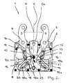
- a bezel 1 which serves for clamping and / or for holding a Maschinenstükkes W on a machine tool and in particular a lathe.
- the bezel 1 has a housing 2, in which three adjustable in a common plane holding members 3, 4, 5 are mounted.
- the two outer holding members 3 and 4 are formed as an angle lever, which are mounted in its central region via pivot pins 6, 7 pivotally mounted in the housing 2.
- the middle holding member 5 is arranged centrally between the two outer holding members 3, 4 and guided radially adjustable to the workpiece W. Of the workpiece W only the clamping position is shown in the drawing, which does not change regardless of the size of the workpiece to be clamped. The adjustment takes place via a not shown adjusting mechanism.
- the middle holding member 5 has a clamping surface 5a on its end face directed toward the tool.
- control surfaces 8, 9 are formed on the middle holding member 5, against which the projecting into the housing 2 free ends of the two outer holding members 3 and 4.
- the control surfaces 8, 9 and the free ends of the outer support members 3, 4 cooperate to implement a rectilinear movement of the central support member 5 in the direction of the tool W in a pivoting movement of the outer support members 3, 4 and so in the in FIG. 1 bring shown clamping position.
- the outer holding members 3, 4 are additionally coupled to the middle holding member 5 in such a way that the outer holding members 3, 4 are automatically inserted into their in FIG. 2 illustrated opened Position are returned when the middle holding member 5 from its clamping position ( Fig. 1 ) is moved downwards by the tool W in the drawing.
- an angle lever 10, 11 is assigned to each outer holding member 3, 4, which is mounted on the middle holding member 5 near its control surfaces 8, 9 pivotally via a hinge pin 12, 13.
- the one end of each angle lever 10, 11 is provided with a pin 14, 15, which engages in a rectilinear link 16, 17, which is formed in the protruding into the housing 2 inner lever of the associated outer support member 4, 5, and therein is guided.
- each angle lever 10, 11 is guided on the housing 2 via a link-pin arrangement.
- a curved gate 18, 19 is formed, in which a housing 2 held on the pin 20, 21 is guided.
- the pin 20, 21 is provided in the vicinity of the longitudinal axis X of the bezel 1.
- the scenes 18, 19 of the two angle levers 10, 11 are formed such that the outer holding members 3, 4, even with a return of the middle holding member 5 on the control surfaces 8, 9 necessarily abut. Concretely, when the middle holding member 5 is retracted, the pivot pins 12, 13 provided thereon and the associated angle levers 10, 11 are also moved axially.
- This axial movement is via the slide-pin arrangement between the angle lever 10, 11 and the housing 2 in an additional pivotal movement of the angle lever 10, 11 relative to the middle holding member. 5 implemented.
- the two outer holding members 3, 4 via their in FIG. 2 shown opened position can be further pivoted out. It is provided that the left in the drawing left outer support member 3 is pivoted further in its end position than the right outer support member 4.
- a first section 18a, 19a of the two scenes 18, 19, which movement between the clamping position and the open position controls in each case a second link section 18b, 19b, which is configured differently in the scenes 18, 19 of the two angle levers 10, 11.
- the gate 19 of the right outer support member 4 associated angle lever 11 of the second link portion 19 b is designed so that the associated right outer support member 4 from the in FIG. 2 shown opened position in his in FIG.
- the left angle lever 10 is guided on the housing 2 by a second slide-pin arrangement with a crank lever 10 provided in the gate 22 and a guided therein and held on the housing 2 pin 23.
- This second slide-pin arrangement is designed so that it takes over the leadership of the angle lever 10 and thus the movement of the left outer support member 3 in such a way that the left outer support member 3 from the in FIG. 2 shown opened position in the in FIG. 3 shown end position is further pivoted when the middle holding member 5 from its the open position of the bezel 1 corresponding position (see FIG. 2 ) is further withdrawn, as in FIG. 3 is shown.
Landscapes
- Engineering & Computer Science (AREA)
- Mechanical Engineering (AREA)
- Machine Tool Units (AREA)
- Pivots And Pivotal Connections (AREA)
- Holders For Apparel And Elements Relating To Apparel (AREA)
- Fittings On The Vehicle Exterior For Carrying Loads, And Devices For Holding Or Mounting Articles (AREA)
- Cutting Tools, Boring Holders, And Turrets (AREA)
- Jigs For Machine Tools (AREA)
Priority Applications (7)
| Application Number | Priority Date | Filing Date | Title |
|---|---|---|---|
| DE502007005286T DE502007005286D1 (de) | 2007-11-08 | 2007-11-08 | Lünette |
| EP07021706A EP2058084B1 (fr) | 2007-11-08 | 2007-11-08 | Lunette |
| AT07021706T ATE483550T1 (de) | 2007-11-08 | 2007-11-08 | Lünette |
| PCT/EP2008/009062 WO2009059708A1 (fr) | 2007-11-08 | 2008-10-27 | Lunette |
| US12/742,199 US8286955B2 (en) | 2007-11-08 | 2008-10-27 | Steady rest |
| CN2008801153454A CN101855041B (zh) | 2007-11-08 | 2008-10-27 | 固定支架 |
| JP2010532472A JP5244914B2 (ja) | 2007-11-08 | 2008-10-27 | 固定振れ止め |
Applications Claiming Priority (1)
| Application Number | Priority Date | Filing Date | Title |
|---|---|---|---|
| EP07021706A EP2058084B1 (fr) | 2007-11-08 | 2007-11-08 | Lunette |
Publications (2)
| Publication Number | Publication Date |
|---|---|
| EP2058084A1 true EP2058084A1 (fr) | 2009-05-13 |
| EP2058084B1 EP2058084B1 (fr) | 2010-10-06 |
Family
ID=38969475
Family Applications (1)
| Application Number | Title | Priority Date | Filing Date |
|---|---|---|---|
| EP07021706A Active EP2058084B1 (fr) | 2007-11-08 | 2007-11-08 | Lunette |
Country Status (7)
| Country | Link |
|---|---|
| US (1) | US8286955B2 (fr) |
| EP (1) | EP2058084B1 (fr) |
| JP (1) | JP5244914B2 (fr) |
| CN (1) | CN101855041B (fr) |
| AT (1) | ATE483550T1 (fr) |
| DE (1) | DE502007005286D1 (fr) |
| WO (1) | WO2009059708A1 (fr) |
Cited By (4)
| Publication number | Priority date | Publication date | Assignee | Title |
|---|---|---|---|---|
| US20120255407A1 (en) * | 2011-03-29 | 2012-10-11 | Eckhard Maurer | Steady rest |
| EP2583786A1 (fr) * | 2011-10-20 | 2013-04-24 | Atlings Maskinfabrik AB | Lunette |
| US20160332271A1 (en) * | 2015-05-12 | 2016-11-17 | Smw-Autoblok Spannsysteme Gmbh | Steady rest |
| WO2017042031A1 (fr) * | 2015-09-10 | 2017-03-16 | Walter Maschinenbau Gmbh | Dispositif d'actionnement pour une lunette |
Families Citing this family (15)
| Publication number | Priority date | Publication date | Assignee | Title |
|---|---|---|---|---|
| CN102085618B (zh) * | 2009-12-03 | 2012-09-05 | 安东石油技术(集团)有限公司 | 具有双重调节功能的套管加工中心架 |
| DE102010026663A1 (de) * | 2010-07-09 | 2012-01-12 | Emag Holding Gmbh | Schleifmaschine zum Schleifen von Nockenscheiben |
| EP2505303B1 (fr) * | 2011-03-29 | 2014-05-07 | SMW-AUTOBLOK Spannsysteme GmbH | Lunette |
| DE102011100965B4 (de) * | 2011-05-09 | 2013-02-28 | Viega Gmbh & Co. Kg | Pressbacke und Verfahren zum Herstellen einer Pressverbindung |
| EP2540438B1 (fr) * | 2011-07-01 | 2013-05-29 | SMW-AUTOBLOK Spannsysteme GmbH | Lunette |
| CN102601555A (zh) * | 2012-03-26 | 2012-07-25 | 无锡华联科技集团有限公司 | Fcb单面焊接装置的停车锁紧机构 |
| CN102935626A (zh) * | 2012-10-26 | 2013-02-20 | 铜陵恒盛轨道装备有限责任公司 | 一种旋转紧固装置 |
| JP5821134B2 (ja) * | 2013-01-28 | 2015-11-24 | Smc株式会社 | クランプ装置 |
| KR101438631B1 (ko) * | 2013-05-07 | 2014-09-05 | 현대자동차 주식회사 | 차량용 패널 지그장치의 각도 조절 클램프 |
| US9925066B2 (en) * | 2013-08-13 | 2018-03-27 | Arthrex, Inc. | Surgical impactor/extractor assembly and method of use |
| US9442349B2 (en) * | 2013-12-16 | 2016-09-13 | Carson Optical, Inc. | Self-centering mechanism, a clamping device for an electronic device and means for their integration |
| CN104191358A (zh) * | 2014-07-29 | 2014-12-10 | 湖南海捷精密工业有限公司 | 一种液压驱动中心架 |
| EP3093103B1 (fr) * | 2015-05-12 | 2017-07-12 | SMW-Autoblok Spannsysteme GmbH | Lunette |
| US10363642B2 (en) * | 2016-01-04 | 2019-07-30 | Carson Optical, Inc. | Locking centering mechanism |
| DE102020118730A1 (de) | 2020-07-15 | 2022-01-20 | Rheinisch-Westfälische Technische Hochschule (Rwth) Aachen | Greifer zum Greifen von Objekten |
Citations (4)
| Publication number | Priority date | Publication date | Assignee | Title |
|---|---|---|---|---|
| DE3543806A1 (de) * | 1985-12-12 | 1987-06-25 | Smw Spanneinrichtungen | Luenette |
| DE3719103A1 (de) * | 1987-06-06 | 1988-12-22 | Smw Spanneinrichtungen | Luenette |
| EP0562180A1 (fr) * | 1992-03-21 | 1993-09-29 | SMW-Autoblok Spannsysteme GmbH | Lunette |
| DE19950706A1 (de) * | 1999-10-21 | 2001-05-10 | Smw Autoblok Spannsysteme Gmbh | Aufspanneinrichtung |
Family Cites Families (13)
| Publication number | Priority date | Publication date | Assignee | Title |
|---|---|---|---|---|
| US1733773A (en) * | 1927-12-12 | 1929-10-29 | Dave P Rajek | Combination vise and gripping tool |
| US1910833A (en) * | 1931-07-18 | 1933-05-23 | Edwin S Hippey | Tool for rail joints |
| US2591636A (en) * | 1950-03-17 | 1952-04-01 | Floyd O Thompson | Pivoted-jaw wrench having nut-actuated and slidable cam-wedge |
| DE1602740A1 (de) * | 1967-06-06 | 1970-04-16 | Bruno Dietl | Einrichtung zum Aufspannen und/oder zur Halterung eines Werkstueckes auf Drehmaschinen |
| GB2089708B (en) * | 1980-12-18 | 1984-02-22 | Index Werke Kg Hahn & Tessky | Steady for holding rod-like circular cross-section components |
| DE3137149C2 (de) * | 1981-09-18 | 1983-09-01 | SMW Schneider & Weißhaupt GmbH, 7996 Meckenbeuren | Lünette mit zwei oder mehreren auf ein einzuspannendes Werkstück einwirkenden Haltegliedern |
| JPH057355Y2 (fr) * | 1990-11-10 | 1993-02-24 | ||
| FR2672834B1 (fr) * | 1991-02-18 | 1993-05-21 | Essilor Int | Organe de serrage et de prehension. |
| DE4238613A1 (de) * | 1992-11-16 | 1994-05-19 | Smw Schneider & Weishaupt Gmbh | Selbstzentrierende Lünette |
| US6665919B1 (en) * | 2001-08-22 | 2003-12-23 | Lisle Corporation | Windshield wiper arm puller |
| CN200967089Y (zh) * | 2006-10-17 | 2007-10-31 | 华中科技大学 | 一种自动定心中心架 |
| ATE429305T1 (de) * | 2007-05-26 | 2009-05-15 | Smw Autoblok Spannsysteme Gmbh | Lünette |
| DE102007029492B3 (de) * | 2007-06-26 | 2009-01-29 | Smw-Autoblok Spannsysteme Gmbh | Lünette |
-
2007
- 2007-11-08 AT AT07021706T patent/ATE483550T1/de active
- 2007-11-08 DE DE502007005286T patent/DE502007005286D1/de active Active
- 2007-11-08 EP EP07021706A patent/EP2058084B1/fr active Active
-
2008
- 2008-10-27 CN CN2008801153454A patent/CN101855041B/zh active Active
- 2008-10-27 JP JP2010532472A patent/JP5244914B2/ja active Active
- 2008-10-27 US US12/742,199 patent/US8286955B2/en active Active
- 2008-10-27 WO PCT/EP2008/009062 patent/WO2009059708A1/fr active Application Filing
Patent Citations (5)
| Publication number | Priority date | Publication date | Assignee | Title |
|---|---|---|---|---|
| DE3543806A1 (de) * | 1985-12-12 | 1987-06-25 | Smw Spanneinrichtungen | Luenette |
| DE3719103A1 (de) * | 1987-06-06 | 1988-12-22 | Smw Spanneinrichtungen | Luenette |
| EP0562180A1 (fr) * | 1992-03-21 | 1993-09-29 | SMW-Autoblok Spannsysteme GmbH | Lunette |
| EP0562180B1 (fr) | 1992-03-21 | 1995-11-02 | SMW-Autoblok Spannsysteme GmbH | Lunette |
| DE19950706A1 (de) * | 1999-10-21 | 2001-05-10 | Smw Autoblok Spannsysteme Gmbh | Aufspanneinrichtung |
Cited By (9)
| Publication number | Priority date | Publication date | Assignee | Title |
|---|---|---|---|---|
| US20120255407A1 (en) * | 2011-03-29 | 2012-10-11 | Eckhard Maurer | Steady rest |
| US9038510B2 (en) * | 2011-03-29 | 2015-05-26 | Smw-Autoblok Spannsysteme Gmbh | Steady rest |
| RU2594767C2 (ru) * | 2011-03-29 | 2016-08-20 | Смв-Аутоблок Шпаннзистеме Гмбх | Люнет |
| EP2583786A1 (fr) * | 2011-10-20 | 2013-04-24 | Atlings Maskinfabrik AB | Lunette |
| US20160332271A1 (en) * | 2015-05-12 | 2016-11-17 | Smw-Autoblok Spannsysteme Gmbh | Steady rest |
| US9969039B2 (en) * | 2015-05-12 | 2018-05-15 | Smw-Autoblok Spannsysteme Gmbh | Steady rest |
| WO2017042031A1 (fr) * | 2015-09-10 | 2017-03-16 | Walter Maschinenbau Gmbh | Dispositif d'actionnement pour une lunette |
| AU2016318561B2 (en) * | 2015-09-10 | 2019-06-27 | Walter Maschinenbau Gmbh | Actuating device for a steady rest |
| US10357858B2 (en) | 2015-09-10 | 2019-07-23 | Walter Maschinenbau Gmbh | Actuating device for a steady rest |
Also Published As
| Publication number | Publication date |
|---|---|
| CN101855041B (zh) | 2012-11-07 |
| ATE483550T1 (de) | 2010-10-15 |
| WO2009059708A1 (fr) | 2009-05-14 |
| US20100252976A1 (en) | 2010-10-07 |
| CN101855041A (zh) | 2010-10-06 |
| JP2011502803A (ja) | 2011-01-27 |
| EP2058084B1 (fr) | 2010-10-06 |
| DE502007005286D1 (de) | 2010-11-18 |
| JP5244914B2 (ja) | 2013-07-24 |
| US8286955B2 (en) | 2012-10-16 |
Similar Documents
| Publication | Publication Date | Title |
|---|---|---|
| EP2058084B1 (fr) | Lunette | |
| EP0700742B1 (fr) | Embarreur automatique pour machines-outil, en particulier pour tours automatiques | |
| DE102019129976B4 (de) | Werkzeugwechselvorrichtung eines Werkzeugmagazins | |
| DE112017004511B4 (de) | Schließvorrichtung | |
| EP2743138B1 (fr) | Dispositif de protection de bordure de portière | |
| DE112008004152T5 (de) | Bewegbarer Windabweiser | |
| EP4000460B1 (fr) | Dispositif destiné à déplacer une partie de meuble mobile | |
| DE19624486A1 (de) | Werkzeughalter zur Verwendung in einem automatischen Werkzeugwechsler | |
| DE2163499A1 (de) | Werkzeugmaschine mit automatischer werkzeug-wechselvorrichtung | |
| EP2907618A1 (fr) | Recouvrement de machine | |
| DE102013214221B3 (de) | Vorrichtung und Verfahren zur Blockierung einer Schnellverstellung einer Gewindespindel | |
| EP2644817B1 (fr) | Entraînement pour un battant d'une fenêtre ou similaire | |
| EP3897295B1 (fr) | Dispositif de fermeture automatique | |
| EP0398193A1 (fr) | Charnière, notamment pour articuler une porte ou un volet à une paroi de suspension d'un corps | |
| EP2744963B1 (fr) | Dispositif pour rétracter une partie de meuble mobile dans une position intermédiaire | |
| DE602004003344T2 (de) | Fahrzeug, insbesondere schienenfahrzeug, mit rückziehbarer kupplung | |
| EP2103367A1 (fr) | Dispositif de serrage pour objets, par exemple pour des pièces usinées devant être traitées | |
| DE102008051137A1 (de) | Vorrichtung zum automatischen Werkzeug- oder Werkstückträgerwechsel | |
| EP3542963A1 (fr) | Tenseur | |
| EP1961290B1 (fr) | Dispositif de verrouillage pour ciseaux | |
| EP3890910A1 (fr) | Tête de forage pour le pochage de contours intérieurs non cylindriques | |
| EP3928660B1 (fr) | Dispositif d'auto-traction pour une pièce de meuble télescopique | |
| DE102004007536B3 (de) | Doppelgelenkscharnier | |
| DE102013221903B4 (de) | Handschaltgetriebe und Verfahren zum Herstellen eines Schieberahmens für ein Handschaltgetriebe | |
| EP4164450B1 (fr) | Dispositif auto-rétractable |
Legal Events
| Date | Code | Title | Description |
|---|---|---|---|
| PUAI | Public reference made under article 153(3) epc to a published international application that has entered the european phase |
Free format text: ORIGINAL CODE: 0009012 |
|
| AK | Designated contracting states |
Kind code of ref document: A1 Designated state(s): AT BE BG CH CY CZ DE DK EE ES FI FR GB GR HU IE IS IT LI LT LU LV MC MT NL PL PT RO SE SI SK TR |
|
| AX | Request for extension of the european patent |
Extension state: AL BA HR MK RS |
|
| 17P | Request for examination filed |
Effective date: 20090907 |
|
| AKX | Designation fees paid |
Designated state(s): AT CH DE FR IT LI |
|
| 17Q | First examination report despatched |
Effective date: 20100108 |
|
| GRAP | Despatch of communication of intention to grant a patent |
Free format text: ORIGINAL CODE: EPIDOSNIGR1 |
|
| GRAS | Grant fee paid |
Free format text: ORIGINAL CODE: EPIDOSNIGR3 |
|
| GRAA | (expected) grant |
Free format text: ORIGINAL CODE: 0009210 |
|
| AK | Designated contracting states |
Kind code of ref document: B1 Designated state(s): AT CH DE FR IT LI |
|
| REG | Reference to a national code |
Ref country code: CH Ref legal event code: EP |
|
| REF | Corresponds to: |
Ref document number: 502007005286 Country of ref document: DE Date of ref document: 20101118 Kind code of ref document: P |
|
| PLBE | No opposition filed within time limit |
Free format text: ORIGINAL CODE: 0009261 |
|
| STAA | Information on the status of an ep patent application or granted ep patent |
Free format text: STATUS: NO OPPOSITION FILED WITHIN TIME LIMIT |
|
| 26N | No opposition filed |
Effective date: 20110707 |
|
| REG | Reference to a national code |
Ref country code: DE Ref legal event code: R097 Ref document number: 502007005286 Country of ref document: DE Effective date: 20110707 |
|
| PG25 | Lapsed in a contracting state [announced via postgrant information from national office to epo] |
Ref country code: IT Free format text: LAPSE BECAUSE OF NON-PAYMENT OF DUE FEES Effective date: 20101108 |
|
| REG | Reference to a national code |
Ref country code: FR Ref legal event code: PLFP Year of fee payment: 9 |
|
| REG | Reference to a national code |
Ref country code: FR Ref legal event code: PLFP Year of fee payment: 10 |
|
| REG | Reference to a national code |
Ref country code: FR Ref legal event code: PLFP Year of fee payment: 11 |
|
| PGFP | Annual fee paid to national office [announced via postgrant information from national office to epo] |
Ref country code: AT Payment date: 20191111 Year of fee payment: 13 |
|
| REG | Reference to a national code |
Ref country code: AT Ref legal event code: MM01 Ref document number: 483550 Country of ref document: AT Kind code of ref document: T Effective date: 20201108 |
|
| PG25 | Lapsed in a contracting state [announced via postgrant information from national office to epo] |
Ref country code: AT Free format text: LAPSE BECAUSE OF NON-PAYMENT OF DUE FEES Effective date: 20201108 |
|
| P01 | Opt-out of the competence of the unified patent court (upc) registered |
Effective date: 20230628 |
|
| PGFP | Annual fee paid to national office [announced via postgrant information from national office to epo] |
Ref country code: IT Payment date: 20231124 Year of fee payment: 17 Ref country code: FR Payment date: 20231120 Year of fee payment: 17 Ref country code: DE Payment date: 20231121 Year of fee payment: 17 Ref country code: CH Payment date: 20231201 Year of fee payment: 17 |