EP2054785B1 - Heissleimauftragssystem und verfahren zur regelung und überwachung des heissleimauftragssystems - Google Patents
Heissleimauftragssystem und verfahren zur regelung und überwachung des heissleimauftragssystems Download PDFInfo
- Publication number
- EP2054785B1 EP2054785B1 EP07786592.1A EP07786592A EP2054785B1 EP 2054785 B1 EP2054785 B1 EP 2054785B1 EP 07786592 A EP07786592 A EP 07786592A EP 2054785 B1 EP2054785 B1 EP 2054785B1
- Authority
- EP
- European Patent Office
- Prior art keywords
- hot
- application system
- glue application
- machine
- monitoring
- Prior art date
- Legal status (The legal status is an assumption and is not a legal conclusion. Google has not performed a legal analysis and makes no representation as to the accuracy of the status listed.)
- Revoked
Links
Images


Classifications
-
- C—CHEMISTRY; METALLURGY
- C09—DYES; PAINTS; POLISHES; NATURAL RESINS; ADHESIVES; COMPOSITIONS NOT OTHERWISE PROVIDED FOR; APPLICATIONS OF MATERIALS NOT OTHERWISE PROVIDED FOR
- C09J—ADHESIVES; NON-MECHANICAL ASPECTS OF ADHESIVE PROCESSES IN GENERAL; ADHESIVE PROCESSES NOT PROVIDED FOR ELSEWHERE; USE OF MATERIALS AS ADHESIVES
- C09J5/00—Adhesive processes in general; Adhesive processes not provided for elsewhere, e.g. relating to primers
-
- B—PERFORMING OPERATIONS; TRANSPORTING
- B05—SPRAYING OR ATOMISING IN GENERAL; APPLYING FLUENT MATERIALS TO SURFACES, IN GENERAL
- B05C—APPARATUS FOR APPLYING FLUENT MATERIALS TO SURFACES, IN GENERAL
- B05C11/00—Component parts, details or accessories not specifically provided for in groups B05C1/00 - B05C9/00
- B05C11/10—Storage, supply or control of liquid or other fluent material; Recovery of excess liquid or other fluent material
- B05C11/1002—Means for controlling supply, i.e. flow or pressure, of liquid or other fluent material to the applying apparatus, e.g. valves
- B05C11/1007—Means for controlling supply, i.e. flow or pressure, of liquid or other fluent material to the applying apparatus, e.g. valves responsive to condition of liquid or other fluent material
-
- B—PERFORMING OPERATIONS; TRANSPORTING
- B05—SPRAYING OR ATOMISING IN GENERAL; APPLYING FLUENT MATERIALS TO SURFACES, IN GENERAL
- B05C—APPARATUS FOR APPLYING FLUENT MATERIALS TO SURFACES, IN GENERAL
- B05C11/00—Component parts, details or accessories not specifically provided for in groups B05C1/00 - B05C9/00
- B05C11/10—Storage, supply or control of liquid or other fluent material; Recovery of excess liquid or other fluent material
- B05C11/1042—Storage, supply or control of liquid or other fluent material; Recovery of excess liquid or other fluent material provided with means for heating or cooling the liquid or other fluent material in the supplying means upstream of the applying apparatus
-
- B—PERFORMING OPERATIONS; TRANSPORTING
- B05—SPRAYING OR ATOMISING IN GENERAL; APPLYING FLUENT MATERIALS TO SURFACES, IN GENERAL
- B05C—APPARATUS FOR APPLYING FLUENT MATERIALS TO SURFACES, IN GENERAL
- B05C5/00—Apparatus in which liquid or other fluent material is projected, poured or allowed to flow on to the surface of the work
- B05C5/001—Apparatus in which liquid or other fluent material is projected, poured or allowed to flow on to the surface of the work incorporating means for heating or cooling the liquid or other fluent material
-
- B—PERFORMING OPERATIONS; TRANSPORTING
- B05—SPRAYING OR ATOMISING IN GENERAL; APPLYING FLUENT MATERIALS TO SURFACES, IN GENERAL
- B05C—APPARATUS FOR APPLYING FLUENT MATERIALS TO SURFACES, IN GENERAL
- B05C5/00—Apparatus in which liquid or other fluent material is projected, poured or allowed to flow on to the surface of the work
- B05C5/02—Apparatus in which liquid or other fluent material is projected, poured or allowed to flow on to the surface of the work the liquid or other fluent material being discharged through an outlet orifice by pressure, e.g. from an outlet device in contact or almost in contact, with the work
- B05C5/0245—Apparatus in which liquid or other fluent material is projected, poured or allowed to flow on to the surface of the work the liquid or other fluent material being discharged through an outlet orifice by pressure, e.g. from an outlet device in contact or almost in contact, with the work for applying liquid or other fluent material to a moving work of indefinite length, e.g. to a moving web
Definitions
- the invention relates to a hot glue application system and a method for controlling and monitoring the hot glue application system.
- Hot glue also known as hot melt or hot melt, is used in industry in a wide variety of applications to bond materials or products together.
- the US 5,604,681 relates to a system for producing mixtures of liquids, which are fed via feed hoses a mixer. Using various readable data carrier is determined which of the delivery hoses are connected to a mixer. Provided for liquid sources shut-off valves are controlled accordingly.
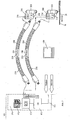
- melter 100 generally includes one or more heatable delivery hoses 200 and one or more heatable application valves 300.
- the heatable delivery hoses 200 serve to supply the application valves 300 with liquid hotmelt. They are heated by a heater 210 to keep the hot melt supplied from the melter 100 in a liquid state. To maintain the operating temperature, the actual temperature is detected with the temperature sensor 112 and reported to the controller 170 for the control.
- the heatable application valves 300 provide an electrically or electropneumatically actuated closure member and a nozzle for the metering and positioning of a hot glue portion 20 to be applied to the product to be bonded. They are heated by a heater 310 to remove the hot glue supplied by the melter 100 via the heatable delivery tubes 200 so far as to liquefy that it depends on the application with the required viscosity and temperature can be applied through the nozzle. To maintain the operating temperature, the actual temperature is detected with the temperature sensor 320 and reported to the controller 170 for the control.
- a variable number of heatable delivery hoses 200 and heatable application valves with variable heat output and control behavior can be connected to the melter 100.
- the configuration of the hot glue application system may change more frequently even after the initial installation, if different products are glued, if the hot glue is changed, or if one of the components fails, a replacement component whose properties differ from the failed component is connected.
- the heating time of the hot glue application system and the deviation of the operating temperature from the set value of the individual heating circuits are important application parameters that directly influence the productivity and operational safety of such systems.
- multi-zone temperature control and monitoring 171 requires the control parameters, such as dead time and gain, as well as other technical data, such as heat output and maximum temperatures, of all connected components.
- the state of the art is self-optimization algorithms in digital controllers, which are started either manually, cyclically or during the initialization of the controller and automatically record the control parameters via test procedures. These algorithms are only successful if connected to a Heating circuit, the deviation of the control parameters from the current values is automatically detected or in each case a new connection, an optimization cycle is triggered manually.
- the limit values for the heating power and the operating temperature can not be determined with this method. This is particularly critical if a defect in the heating circuit occurs during operation or a defective component is connected, since the control then adapts the control response to the newly determined parameters without alarm triggering. This can have a negative effect on the quality of the hot glue application and lead to serious safety risks if the maximum temperatures are exceeded.
- the algorithms offer no possibility of optimizing the behavior of the hot glue application system as a whole, such as the energy consumption or the overall heating time.
- the electronic controller 170 therefore operates either with permanently set average control parameters and the maximum values for the heating power and operating temperature or a self-optimization to be initiated manually.
- Another problem is that the components used all have only a limited life and the failure of only one component can lead to the failure of the entire hot glue application system.
- a known method for increasing the availability of an automated production plant consists in the preventive maintenance of the components of a such facility.
- a preventive repair or the preventive replacement of components is made.
- a prerequisite for the organization of preventive maintenance is the recording and availability of the current operating time of the individual components. To do this, all events that cause the operating time of the individual components to deviate from the operating time of the entire system must be documented in a logbook in a costly and error-prone manner by manual entry. In known hot glue application systems, therefore, only the service life of the melter 100 is monitored. An automatic monitoring of the operating time of the connected components does not take place.
- the invention is therefore based on the object to provide a method and apparatus for applying hot glue, which ensures a safe gluing of the products to be bonded and their reliability is increased even after an exchange of components.
- the components contain a machine-readable and preferably also machine-writable data carrier, which can be used for automatic adjustment of the control parameters by the Multi-zone temperature control and monitoring required technical data can be stored in the components themselves. Due to this measure is achieved that after an exchange of one or more components, an automatic adaptation of the control parameters by the multi-zone temperature control and monitoring takes place, so that all components of the hot glue application system are always operated below the optimum temperature.
- the development of the hot glue application system according to the invention is also particularly suitable for monitoring the operation of the heating circuits connected to the temperature control and monitoring, because it is necessary for this that the controller 170 has the control parameters and other technical data of all connected components, since only then without additional sensors conclusions can be drawn on the functionality of the components.
- different types of temperature sensors can be monitored for short circuit and sensor breakage and their calibration can be automatically adjusted or partial short circuits of the heating coil or heating cartridges or installations of the order valves with excessive heat dissipation can be detected by evaluating the temperature gradient with full control of the heating circuit, if the standard values in the Control are deposited.
- the controller 170 In order to evaluate the maintenance status and to diagnose a hot glue system, it is necessary for the controller 170 to have information about the operating time and the exceeding of limit parameters of the melter 100 and the connected heatable delivery tubes 200 and the heatable application valves 300. It is advantageous if this information is stored in the hoses and job valves themselves, so that after a repair and when connecting components that were already in use, the previously achieved operating time and the exceeding of specified limit parameters automatically reported to the controller 170 becomes.
- the controller communicates wired or wireless with the data carriers in the connected components and the controller cyclically updates the operating hours counters contained in the components and the data memories for the limit parameters.
- the operating time and the reached limit parameters may thus be interrogated either via the controller 170 when the components are connected to the melter 100, or after separation from the melter 100 also externally when the component for example, undergoes a repair.
- the data carrier is preferably also machine-writable.
- the controller 170 can communicate with the higher level control of the production plant or an external monitoring and diagnostic device, so that the information obtained from the data carriers in the components, other instances are available.
- the device for communication has a connection for various fieldbus systems or the Internet. In this way, it is possible to organize a component failure, for example remote diagnostics via the Internet.
- the controller 170 contains a wired device 173 (see FIG. Fig. 2 ) or a wireless device 174 (see FIG. Fig. 3 ) for communication with data carriers in the connected components.
- the conveying hoses 200 each contain one or more machine-readable and preferably also writable data carriers 230 and the order valves 300 each contain one or more machine-readable and preferably also writable data carriers 330, such as microprocessor systems, memory devices, codes or RFID, wired or wireless, optical, transmit data to the device 173 or the device 174 by radio or by other suitable methods, and preferably can also receive data from the device 174.
- machine-readable and preferably also writable data carriers 230 and the order valves 300 each contain one or more machine-readable and preferably also writable data carriers 330, such as microprocessor systems, memory devices, codes or RFID, wired or wireless, optical, transmit data to the device 173 or the device 174 by radio or by other suitable methods, and preferably can also receive data from the device 174.
- These disks are used in the production or repair of the components an external writing and reading unit 400 with the type-specific control parameters, such as dead time and gain factor, and other technical data, such
- the data carriers transmit their data to the device 173 or the device 174 during initialization and / or cyclically as well as when changing the system configuration. These are then used by the controller 170 to provide optimum control and To organize monitoring of the connected components and the overall system.
- the device 173 or the device 174 in turn transmit during initialization and / or cyclically and when changing the system configuration data, such as maximum setpoint and actual parameters or accumulated operating hours, for storage to the data carriers of the connected components, which then advantageous for the diagnosis and preventive maintenance can be used.
- the device for communication 173 or 174 via a port 175 for data exchange via fieldbus with higher-level controllers or via the Internet with external monitoring devices can be organized.
Landscapes
- Chemical & Material Sciences (AREA)
- Organic Chemistry (AREA)
- Coating Apparatus (AREA)
- Testing And Monitoring For Control Systems (AREA)
- Application Of Or Painting With Fluid Materials (AREA)
Description
- Die Erfindung betrifft ein Heißleimauftragssystem und ein Verfahren zur Regelung und Überwachung des Heißleimauftragssystems.
- Heißleim, auch bekannt als Schmelzklebstoff oder Hotmelt, wird in der Industrie in den verschiedenartigsten Anwendungen eingesetzt, um Materialien oder Produkte miteinander zu verkleben.
- Aus der
US 5,700,322 ist ein Heißleimauftragssystem mit beheizten Förderschläuchen und Auftragsventilen sowie einem Temperaturregler bekannt. - Die
US 5,604,681 betrifft ein System zur Herstellung von Gemischen von Flüssigkeiten, die über Förderschläuche einen Mischer zugeführt werden. Mittels verschiedener lesbarer Datenträger wird ermittelt, welche der Förderschläuche mit einem Mischer verbunden sind. An Flüssigkeitsquellen vorgesehene Absperrventile werden entsprechend angesteuert. - Ein zum Stand der Technik gehörendes Heißleimauftragssystem (s.
Abb. 1 ) umfasst generell ein Schmelzgerät 100 einen oder mehrere beheizbare Förderschläuche 200 und ein oder mehrere beheizbare Auftragsventile 300. - Das Schmelzgerät 100 umfasst folgende Komponenten:
- einen beheizbaren Tank 110, in dem der Heißleim in festem Aggregatzustand als Granulat oder in Blockform aufgegeben wird. Er dient zur Bevorratung und Verflüssigung des Heißleims. Mittels einer Heizung 111, die eine oder mehrere Heizzonen aufweisen kann, wird der Tank soweit erwärmt, dass sich der Heißleim verflüssigt. Zur Einhaltung der Betriebstemperatur wird, je nach Anzahl der Heizzonen, über einen oder mehrere Temperatursensoren 112 die Isttemperatur für die Regelung erfasst.
- eine Pumpe 120, die den aufgeschmolzenen Heißleim zu den angeschlossenen Verbrauchern fördert.
- ein Überdruckventil 130, das bei Überschreitung des Betriebsdrucks die Verbraucherseite entlastet und Heißleim in den Tank 110 zurückleitet.
- einen Filter 140, der verhindert, dass Partikel mit einer Größe, die zur Verstopfung der Auftragsventile führen könnten, zur Verbraucherseite gelangen.
- einen Verteiler 150, der über mehrere Hydraulikanschlüsse verfügt, an die beheizbare Förderschläuche zur Versorgung mit Heißleim angeschlossen werden können.
- eine elektronische Steuerung 170, mit einer Mehrzonen-Temperaturregelung und -überwachung 171 und einem Bedien- und Anzeigegerät 172. Die Mehrzonen-Temperaturregelung und -überwachung sorgt für die Erreichung und Einhaltung der Solltemperatur der Tankheizzonen und über mehrere externe Anschlüsse für die Erreichung und Einhaltung der Solltemperatur für die angeschlossenen beheizbaren Förderschläuche und beheizbaren Auftragsventile sowie für deren Überwachung.
- Die beheizbaren Förderschläuche 200 dienen zur Versorgung der Auftragsventile 300 mit flüssigem Heißleim. Sie werden über eine Heizung 210 erwärmt, um den vom Schmelzgerät 100 zugeführten Heißleim in flüssigem Zustand zu halten. Zur Einhaltung der Betriebstemperatur wird mit dem Temperatursensor 112 die Isttemperatur erfasst und für die Regelung an die Steuerung 170 gemeldet.
- Die beheizbaren Auftragsventile 300 sorgen über ein elektrisch oder elektropneumatisch betätigtes Verschlussorgan und eine Düse für die Dosierung und Positionierung einer auf das zu verklebende Produkt aufzubringenden Heißleimportion 20. Sie werden über eine Heizung 310 erwärmt, um den vom Schmelzgerät 100 über die beheizbaren Förderschläuche 200 zugeführten Heißleim so weit zu verflüssigen, dass er abhängig von der Anwendung mit der benötigten Viskosität und Temperatur über die Düse aufgetragen werden kann. Zur Einhaltung der Betriebstemperatur wird mit dem Temperatursensor 320 die Isttemperatur erfasst und für die Regelung an die Steuerung 170 gemeldet.
- Je nach Anwendung kann an das Schmelzgerät 100 eine variable Anzahl von beheizbaren Förderschläuchen 200 und beheizbaren Auftragsventilen mit variabler Heizleistung und Regelverhalten angeschlossen werden. Die Konfiguration des Heißleimauftragssystems kann auch nach der Erstinstallation häufiger wechseln, wenn abweichende Produkte verklebt werden, der Heißleim verändert wird oder nach Ausfall einer der Komponenten eine Ersatzkomponente angeschlossen wird, deren Eigenschaften verschieden von der ausgefallenen Komponente ist.
- Die Aufheizzeit des Heißleimauftragssystems und die Regelabweichung der Betriebstemperatur vom eingestellten Sollwert der einzelnen Heizkreise sind wichtige Anwendungsparameter, die Produktivität und Betriebssicherheit derartiger Systeme unmittelbar beeinflussen. Zur Optimierung des Regelverhaltens ist es erforderlich, dass die Mehrzonen-Temperaturregelung und -überwachung 171 über die Regelparameter, wie Totzeit und Verstärkungsfaktor, sowie weitere technische Daten, wie Heizleistung und Maximaltemperaturen, sämtlicher angeschlossener Komponenten verfügt.
- Es ist bekannt, die Mehrzonen-Temperaturregelung und -überwachung 171 derart auszugestalten, dass die Regelparameter für die verschiedenen angeschlossenen Komponenten manuell eingegeben werden können.
- Die manuelle Eingabe der Regelparameter ist jedoch bei einem häufigen Wechsel der Komponenten, des Heißleimtyps oder der zu verklebenden Produkte aufwendig und fehlerträchtig.
- Stand der Technik sind Selbstoptimierungsalgorythmen bei digitalen Reglern, die entweder manuell, zyklisch oder bei der Initialisierung der Steuerung gestartet werden und über Testprozeduren die Regelparameter automatisch erfassen. Diese Algorythmen sind aber nur dann erfolgreich, wenn bei Anschluss eines Heizkreises die Abweichung der Regelparameter von den aktuellen Werten automatisch erkannt wird oder bei einem Neuanschluss jeweils manuell ein Optimierungszyklus ausgelöst wird. Die Grenzwerte für die Heizleistung und die Betriebstemperatur können mit diesem Verfahren nicht ermittelt werden. Dies ist insbesondere dann kritisch, wenn während des Betriebs ein Defekt am Heizkreis eintritt oder eine defekte Komponente angeschlossen wird, da die Steuerung dann ohne Alarmauslösung das Regelverhalten an die neu ermittelten Parameter anpasst. Dies kann sich negativ auf die Qualität des Heißleimauftrags auswirken und bei Überschreitung der Maximaltemperaturen zu schwerwiegenden Sicherheitsrisiken führen. Weiterhin bieten die Algorythmen ohne die Kenntnis weiterer technischer Daten zu den angeschlossenen Komponenten keine Möglichkeit, das Verhalten des Heißleimauftragssystems im Ganzen, wie den Energieverbrauch oder die Gesamtaufheizzeit zu optimieren.
- Bei bekannten Heißleimauftragssystemen arbeitet die elektronische Steuerung 170 daher entweder mit fest eingestellten mittleren Regelparametern und den Maximalwerten für die Heizleistung und Betriebstemperatur oder einer manuell auszulösenden Selbstoptimierung.
- Bei bekannten Heißleimauftragssystemen findet ferner lediglich eine Überwachung der Temperaturfühler auf Kurzschluss und Fühlerbruch statt, da in der Regel jeweils nur ein Typ eingesetzt wird, dessen Daten fest in der Steuerung hinterlegt sind. Eine Überwachung der Heizungen findet nicht statt, da die manuelle Eingabe der Heizungsparameter zu aufwendig ist und der zusätzliche Einbau von Sensoren, wie zum Beispiel Stromfühler, den Kostenrahmen sprengt. Problematisch ist dies, wenn als Ersatz beispielsweise einer defekten Heizung eine solche mit anderer Charakteristik eingesetzt wird.
- Ein weiteres Problem besteht darin, dass die eingesetzten Komponenten allesamt nur eine begrenzte Lebensdauer aufweisen und der Ausfall nur einer Komponente zum Ausfall des gesamten Heißleimauftragssystems führen kann.
- Eine bekannte Methode zur Erhöhung der Verfügbarkeit einer automatisierten Produktionsanlage besteht in der präventiven Wartung der Komponenten einer solchen Anlage. Dabei wird ausgehend von der zu erwartenden störungsfreien Betriebsdauer, die mit statistischen Auswertungen oder über praktische Untersuchungen gewonnen wird, eine vorbeugende Reparatur oder der vorbeugende Austausch von Komponenten vorgenommen. Eine Voraussetzung zur Organisation der präventiven Wartung besteht in der Aufzeichnung und Verfügbarkeit der aktuellen Betriebsdauer der einzelnen Komponenten. Dazu müssen in einem Logbuch alle Ereignisse, die bewirken, dass die Betriebsdauer der Einzelkomponenten von der Betriebsdauer der Gesamtanlage abweicht, aufwendig und fehlerträchtig per manueller Eingabe dokumentiert werden. Bei bekannten Heißleimauftragssystemen wird deshalb nur die Betriebsdauer des Schmelzgerätes 100 überwacht. Eine automatische Überwachung der Betriebsdauer der angeschlossenen Komponenten findet nicht statt.
- Zudem erfolgt bei bekannten Heißleimauftragssystemen keine Aufzeichnung der Überschreitung von Grenzparametern in den Komponenten. Damit stehen diese Informationen für die Diagnose nicht zur Verfügung.
- Der Erfindung liegt daher die Aufgabe zugrunde ein Verfahren und eine Vorrichtung zum Auftrag von Heißleim zu schaffen, die auch nach einem Austausch von Komponenten eine sichere Beleimung der zu verklebenden Produkte gewährleistet und deren Betriebssicherheit erhöht ist.
- Diese Aufgabe wird durch das beanspruchte Heißleimauftragssystem bzw. durch das beanspruchte Verfahren gelöst. Vorteilhafte Ausgestaltungen des Verfahrens bzw. der Vorrichtung sind Gegenstand der Unteransprüche.
- Dadurch, dass bei dem erfindungsgemäßen Heißleimauftragssystem, das ein Schmelzgerät und daran angeschlossene Komponenten, wie einen oder mehreren beheizbare Förderschläuche sowie ein oder mehrere beheizbare Auftragsventile umfasst, die Komponenten einen maschinenlesbaren und vorzugsweise auch maschinenbeschreibbaren Datenträger enthalten, können die zur selbsttätigen Anpassung der Regelparameter durch die Mehrzonen-Temperaturregelung und -überwachung erforderlichen technischen Daten in den Komponenten selbst gespeichert werden. Aufgrund dieser Maßnahme wird erreicht, dass nach einem Austausch einer oder mehrerer Komponenten eine selbsttätige Anpassung der Regelparameter durch die Mehrzonen-Temperaturregelung und - überwachung erfolgt, so dass sämtliche Komponenten des Heißleimauftragssystems stets unter der optimalen Temperatur betrieben werden. Die erfindungsgemäße Weiterbildung des Heißleimauftragssystems ist insbesondere auch zur Betriebsüberwachung der an die Temperaturregelung und -überwachung angeschlossenen Heizkreise geeignet, weil es hierzu erforderlich ist, dass die Steuerung 170 über die Regelparameter sowie weitere technische Daten sämtlicher angeschlossener Komponenten verfügt, da nur so ohne zusätzliche Sensorik Rückschlüsse auf die Funktionsfähigkeit der Komponenten gezogen werden können. So können auch unterschiedliche Typen an Temperatursensoren auf Kurzschluss und Fühlerbruch überwacht werden sowie deren Kalibrierung automatisch eingestellt werden oder über die Auswertung des Temperaturgradienten bei Vollaussteuerung des Heizkreises partielle Kurzschlüsse der Heizwendel oder Heizpatronen oder Installationen der Auftragsventile mit überhöhter Wärmeableitung erkannt werden, wenn die Normwerte in der Steuerung hinterlegt sind.
- Zur Bewertung des Wartungszustands und zur Diagnose einer Heißleimanlage ist es erforderlich, dass die Steuerung 170 über Informationen zur Betriebsdauer und zur Überschreitung von Grenzparametern des Schmelzgeräts 100 und der angeschlossenen beheizbaren Förderschläuche 200 und der beheizbaren Auftragsventile 300 verfügt. Dabei ist es von Vorteil, wenn diese Informationen in den Schläuchen und Auftragsventilen selbst hinterlegt werden, damit nach einer Reparatur und beim Anschluss von Komponenten, die schon im Einsatz waren, die bisher erreichte Betriebsdauer und die Überschreitung von festgelegten Grenzparametern automatisch an die Steuerung 170 gemeldet wird. Während des Betriebes kommuniziert die Steuerung bei der Initialisierung und/oder zyklisch sowie bei Veränderung der Systemkonfiguration drahtgebunden oder drahtlos mit den Datenträgern in den angeschlossenen Komponenten und die Steuerung aktualisiert zyklisch die in den Komponenten enthaltenen Betriebsstundenzähler und die Datenspeicher für die Grenzparameter. Die Betriebsdauer und die erreichten Grenzparameter der Komponenten können damit entweder über die Steuerung 170 abgefragt werden, wenn die Komponenten an das Schmelzgerät 100 angeschlossen sind, oder nach der Trennung vom Schmelzgerät 100 auch extern, wenn die Kompo-nente zum Beispiels einer Reparatur unterzogen wird. Hierzu ist der Datenträger vorzugsweise auch maschinenbeschreibbar.
- Zur Überwachung der Heißleimanlage ist es von Vorteil, wenn die Steuerung 170 mit der übergeordneten Steuerung der Produktionsanlage oder einer externen Überwachungs- und Diagnoseeinrichtung Daten austauschen kann, damit die Informationen, die von den Datenträgern in den Komponenten gewonnen werden, weiteren Instanzen zur Verfügung stehen. Dazu verfügt die Einrichtung zur Kommunikation über einen Anschluss für verschiedene Feldbussysteme oder das Internet. So kann beim Ausfall einer Komponente, zum Beispiel eine Ferndiagnose per Internet, organisiert werden.
- Bekannte Heißleimauftragssysteme verfügen über Einrichtungen, um per Feldbus Daten mit anderen Steuerungen auszutauschen. Allerdings ist der Informationsgehalt sehr beschränkt, da die Daten der angeschlossenen Komponenten nicht zur Verfügung stehen.
- In der Zeichnung ist - schematisch - eine bevorzugte Ausführungsform eines erfindungsgemäßen Heißleimauftragssystems dargestellt.
- Die Steuerung 170 enthält neben den üblichen Komponenten zur Regelung und Überwachung der Heizkreise des Schmelzgeräts 100 und der angeschlossenen beheizbaren Förderschläuche 200 sowie der angeschlossenen beheizbaren Auftragsventile 300 eine drahtgebundene Vorrichtung 173 (s.
Abb. 2 ) oder eine drahtlose Vorrichtung 174 (s.Abb. 3 ) zur Kommunikation mit Datenträgern in den angeschlossenen Komponenten. Die Förderschläuche 200 enthalten je einen oder mehrere maschinenlesbare und vorzugsweise auch beschreibbare Datenträger 230 und die Auftragsventile 300 enthalten je einen oder mehrere maschinenlesbare und vorzugsweise auch beschreibbare Datenträger 330, wie zum Beispiel Mikroprozessorsysteme, Speichereinrichtungen, Kodierungen oder RFID, die drahtgebunden oder drahtlos, optisch, per Funk oder mittels anderer geeigneter Verfahren, Daten an die Vorrichtung 173 bzw. die Vorrichtung 174 übermitteln und vorzugsweise auch von dieser empfangen können. Diese Datenträger werden bei der Produktion oder Reparatur der Komponenten mittels einer externen Schreib- und Leseeinheit 400 mit den typspezifischen Regelparametern, wie Totzeit und Verstärkungsfaktor, sowie weiteren technischen Daten, wie Herstellungsdatum, mittlere Lebensdauer, Heizleistung und Maximaltemperaturen, beschrieben. Sind die Komponenten an das Schmelzgerät 100 angeschlossen, übermitteln die Datenträger bei der Initialisierung und/oder zyklisch sowie bei Veränderung der Systemkonfiguration ihre Daten an die Vorrichtung 173 bzw. die Vorrichtung 174. Diese werden dann von der Steuerung 170 genutzt, um eine optimale Regelung und Überwachung der angeschlossenen Komponenten und des Gesamtsystems zu organisieren. Die Vorrichtung 173 bzw. die Vorrichtung 174 übermitteln ihrerseits bei der Initialisierung und/oder zyklisch sowie bei Veränderung der Systemkonfiguration Daten, wie maximale Soll- und Istparameter oder aufgelaufene Betriebsstunden, zur Speicherung an die Datenträger der angeschlossenen Komponenten, die dann vorteilhaft für die Diagnose und präventive Wartung genutzt werden können. - Weiterhin verfügt die Vorrichtung zur Kommunikation 173 bzw. 174 über einen Anschluss 175 zum Datenaustausch per Feldbus mit übergeordneten Steuerungen oder per Internet mit externen Überwachungseinrichtungen. So kann beim Ausfall einer Komponente, zum Beispiel ein Alarmsignal an den Leitstand der Maschine oder eine Ferndiagnose per Internet, organisiert werden.
Claims (12)
- Heißleimauftragssystem mit einem Schmelzgerät (100) und daran angeschlossenen Komponenten, wie einem oder mehreren, beheizbaren Förderschläuchen (200) sowie einem oder mehreren beheizbaren Auftragsventilen (300),
dadurch gekennzeichnet,
dass die Komponenten einen maschinenlesbaren und vorzugsweise auch maschinenbeschreibbaren Datenträger (230, 330) zum Speichern der zur selbsttätigen Anpassung von Regelparametern durch eine Mehrzonen-Temperaturregelung und -überwachung erforderlichen technischen Daten enthalten. - Heißleimauftragssystem nach Anspruch 1, bei dem die maschinenlesbaren und/oder maschinenbeschreibbaren Datenträger (230, 330) ein Mikroprozessorsystem umfassen.
- Heißleimauftragssystem nach Anspruch 1, bei dem die maschinenlesbaren und/oder maschinenbeschreibbaren Datenträger (230, 330) einen oder mehrere Halbleiterspeicher umfassen.
- Heißleimauftragssystem nach Anspruch 1, bei dem die maschinenlesbaren und/oder maschinenbeschreibbaren Datenträger (230, 330) einen magnetisch lesbaren und/oder beschreibbaren Speicher oder Kodierungsträger umfassen.
- Heißleimauftragssystem nach Anspruch 1, bei dem die maschinenlesbaren und/oder maschinenbeschreibbaren Datenträger (230, 330) einen optisch lesbaren und/oder beschreibbaren Speicher oder Kodierungsträger, mit zum Beispiel einem Strich-, 2D- oder 3D-Kod, umfassen.
- Heißleimauftragssystem nach Anspruch 1, bei dem die für die Regelung und Überwachung der Heizkreise des Schmelzgeräts (100) und der angeschlossenen Komponenten dienende Steuerung (170) über eine Einrichtung zur Kommunikation (173, 174) mit den Datenträgern (230, 330) in den Komponenten verfügt.
- Heißleimauftragssystem nach Anspruch 6, bei dem die Kommunikation zwischen der Kommunikationseinrichtung (173, 174) der Steuerung (170) und den Datenträgern (230, 330) in den angeschlossenen Komponenten drahtgebunden über die Anschlussstecker des Schmelzgeräts (100) oder drahtlos auf elektromagnetischem, magnetischem, akustischem oder optischem Wege erfolgt.
- Heißleimauftragssystem nach Anspruch 6 oder 7, bei dem die Einrichtung zur Kommunikation (173, 174) über einen Anschluss verfügt, der per Feldbus mit übergeordneten Steuerungen oder per Internet mit externen Überwachungseinrichtungen Daten austauschen kann.
- Verfahren zur Regelung und Überwachung eines Heißleimauftragssystems mit einem Schmelzgerät (100), das eine Steuerung (170) enthält, und daran angeschlossenen Komponenten, wie einen oder mehreren beheizbaren Förderschläuchen und einem oder mehreren beheizbaren Auftragsventilen (300),
dadurch gekennzeichnet,
dass die Steuerung (170) bei der Initialisierung und/oder zyklisch sowie bei Veränderung der Systemkonfiguration drahtgebunden oder drahtlos mit den Datenträgern (230, 330) in den angeschlossenen Komponenten, die jeweils einen maschinenlesbaren und maschinenbeschreibbaren Datenträger (230, 330) mit zur selbsttätigen Anpassung von Regelparametern durch eine Mehrzonen-Temperaturregelung und -überwachung erforderlichen technischen Daten enthalten, kommuniziert. - Verfahren nach Anspruch 9, bei dem die Steuerung (170) Daten von den angeschlossenen Komponenten erhält und diese nutzt, um die Regelung und Überwachung deren Heizkreise zu optimieren.
- Verfahren nach Anspruch 9 oder 10, bei dem die Steuerung (170) Daten an die Datenträger (230, 330) in den angeschlossenen Komponenten überträgt, die genutzt werden, um deren Diagnose und Wartung zu optimieren.
- Verfahren nach einem der Ansprüche 9 bis 11, bei dem die Steuerung (170) per Feldbus mit übergeordneten Steuerungen oder per Internet mit externen Überwachungseinrichtungen Daten austauscht, die genutzt werden, um die Überwachung des Heißleimauftragssystems zu optimieren und im Fehlerfall eine Ferndiagnose zu ermöglichen.
Applications Claiming Priority (2)
| Application Number | Priority Date | Filing Date | Title |
|---|---|---|---|
| DE102006039839.4A DE102006039839B4 (de) | 2006-08-25 | 2006-08-25 | Heißleimauftragssystem und Verfahren zur Regelung und Überwachung des Heißleimauftragssystems |
| PCT/EP2007/006956 WO2008022708A1 (de) | 2006-08-25 | 2007-08-07 | Heissleimauftragssystem und verfahren zur regelung und überwachung des heissleimauftragssystems |
Publications (2)
| Publication Number | Publication Date |
|---|---|
| EP2054785A1 EP2054785A1 (de) | 2009-05-06 |
| EP2054785B1 true EP2054785B1 (de) | 2014-03-26 |
Family
ID=38535427
Family Applications (1)
| Application Number | Title | Priority Date | Filing Date |
|---|---|---|---|
| EP07786592.1A Revoked EP2054785B1 (de) | 2006-08-25 | 2007-08-07 | Heissleimauftragssystem und verfahren zur regelung und überwachung des heissleimauftragssystems |
Country Status (7)
| Country | Link |
|---|---|
| US (2) | US9840643B2 (de) |
| EP (1) | EP2054785B1 (de) |
| JP (1) | JP5436210B2 (de) |
| CN (1) | CN101506751B (de) |
| DE (2) | DE202006021238U1 (de) |
| ES (1) | ES2465669T3 (de) |
| WO (1) | WO2008022708A1 (de) |
Cited By (6)
| Publication number | Priority date | Publication date | Assignee | Title |
|---|---|---|---|---|
| DE102016006364A1 (de) | 2016-05-30 | 2017-11-30 | Baumer Hhs Gmbh | Heißleimauftragssystem |
| EP2724783B1 (de) | 2012-10-25 | 2018-01-17 | Nordson Corporation | Ausgabesysteme und Verfahren zur Überwachung von Betätigungssignalen für die Diagnostik |
| DE102017002724A1 (de) | 2017-03-21 | 2018-09-27 | Baumer Hhs Gmbh | Vorrichtung und Verfahren zur Erfassung von Verbrauchsdaten für ein Heißleimsystem |
| DE102017003020A1 (de) | 2017-03-29 | 2018-10-04 | Baumer Hhs Gmbh | Verfahren und Vorrichtung zum sicheren Betreiben eines Heißleimsystems |
| EP3306160B1 (de) | 2016-07-15 | 2021-11-17 | Nordson Corporation | Klebstoffübertragungsschlauch mit barriereschicht und verfahren zur verwendung |
| US11880185B2 (en) | 2018-06-04 | 2024-01-23 | Nordson Corporation | Systems and methods for liquid dispensing system communications |
Families Citing this family (41)
| Publication number | Priority date | Publication date | Assignee | Title |
|---|---|---|---|---|
| DE102009033030A1 (de) * | 2009-07-02 | 2011-01-05 | Krones Ag | Leimaufbereitungsvorrichtung |
| EP2404679B1 (de) * | 2010-07-07 | 2017-08-30 | Henkel AG & Co. KGaA | Liefereinheit für ein Anwendungssystem |
| DE102011004024A1 (de) * | 2011-02-14 | 2012-08-16 | Illinois Tool Works Inc. | Steuervorrichtung für eine Pulversprühbeschichtungseinrichtung |
| EP2532444A1 (de) * | 2011-06-07 | 2012-12-12 | Baumer hhs GmbH | Verfahren und Vorrichtung zum Auftrag von viskosen oder fluiden Medien |
| DE102011110281A1 (de) | 2011-06-22 | 2012-12-27 | Baumer Hhs Gmbh | Gegenlage für eine Auftragsvorrichtung |
| CN103826759A (zh) * | 2011-09-13 | 2014-05-28 | 格瑞克明尼苏达有限公司 | 用于防止泵送系统中的填满的方法 |
| IN2014DN03195A (de) | 2011-10-27 | 2015-05-22 | Graco Minnesota Inc | |
| KR20140084255A (ko) | 2011-10-27 | 2014-07-04 | 그라코 미네소타 인크. | 용융기 |
| US9061316B2 (en) * | 2011-10-28 | 2015-06-23 | Nordson Corporation | Mountable device for dispensing heated adhesive |
| US10642286B2 (en) | 2012-04-20 | 2020-05-05 | Nordson Corporation | Device, system, and method for tracking the configuration or operational history of a nozzle in a fluid jetting system |
| DE202012004262U1 (de) * | 2012-05-02 | 2013-08-08 | Baumer Hhs Gmbh | Heißleimauftragssystem |
| DE102012108328B4 (de) | 2012-09-07 | 2019-07-18 | Baumer Hhs Gmbh | Heißleimauftragssystem |
| US9169088B2 (en) | 2012-09-20 | 2015-10-27 | Nordson Corporation | Adhesive dispensing device having optimized cyclonic separator unit |
| US9304028B2 (en) | 2012-09-20 | 2016-04-05 | Nordson Corporation | Adhesive dispensing device having optimized reservoir and capacitive level sensor |
| US10099242B2 (en) | 2012-09-20 | 2018-10-16 | Nordson Corporation | Adhesive melter having pump mounted into heated housing |
| US9200741B2 (en) | 2012-10-25 | 2015-12-01 | Nordson Corporation | Adhesive dispensing system and method using smart melt heater control |
| US9243626B2 (en) | 2012-11-19 | 2016-01-26 | Nordson Corporation | Adhesive dispensing system and method including a pump with integrated diagnostics |
| US10969805B2 (en) | 2013-02-11 | 2021-04-06 | Graco Minnesota Inc. | Paint sprayer distributed control and output volume monitoring architectures |
| KR20150130978A (ko) | 2013-02-11 | 2015-11-24 | 그라코 미네소타 인크. | 유체 도포기 시스템을 위한 원격 모니터링 |
| US9574714B2 (en) * | 2013-07-29 | 2017-02-21 | Nordson Corporation | Adhesive melter and method having predictive maintenance for exhaust air filter |
| DE102013218020A1 (de) * | 2013-09-10 | 2015-03-12 | Krones Ag | Verfahren zur geführten Umstellung einer Behandlungsmaschine |
| US9731486B2 (en) | 2013-09-16 | 2017-08-15 | Nordson Corporation | Heat exchange device with ring shaped thin slit section for use in liquid adhesive systems and related methods |
| US9615405B2 (en) * | 2013-09-16 | 2017-04-04 | Nordson Corporation | Heat exchange devices, liquid adhesive systems, and related methods |
| DE102013111302A1 (de) | 2013-10-14 | 2015-04-16 | Baumer Hhs Gmbh | Auftragskopf, Auftragssystem und Verfahren zur Herstellung eines Auftragskopfes |
| DE102013112686A1 (de) | 2013-11-18 | 2015-05-21 | Baumer Hhs Gmbh | Heißleimauftragssystem und -verfahren |
| DE102013112754A1 (de) | 2013-11-19 | 2015-05-21 | Baumer Hhs Gmbh | Vorrichtung zum Auftrag eines viskosen oder fluiden Auftragsmediums sowie Verfahren zur Herstellung einer derartigen Vorrichtung |
| DE102014017895A1 (de) * | 2014-12-03 | 2016-06-09 | Dürr Systems GmbH | Applikationsanlagenbauteil mit Transponder und/oder Verschleißerkennungseinrichtung |
| EP3051373B1 (de) * | 2015-02-02 | 2019-05-08 | Siemens Aktiengesellschaft | Auswechseln einer defekten Anlagenkomponente in einer Automatisierungsanlage |
| US9796492B2 (en) | 2015-03-12 | 2017-10-24 | Graco Minnesota Inc. | Manual check valve for priming a collapsible fluid liner for a sprayer |
| USD823912S1 (en) * | 2015-09-25 | 2018-07-24 | Baumer Hhs Gmbh | Glue application device |
| DE102015015292B4 (de) | 2015-11-30 | 2019-02-21 | Baumer Hhs Gmbh | Auftragsvorrichtung und Verfahren zum Auftragen von viskosen Medien |
| DE102016006365B3 (de) * | 2016-05-30 | 2017-05-18 | Baumer Hhs Gmbh | Verpackungsmaschine und Steuerungsverfahren einer Verpackungsmaschine |
| DE102016006363B3 (de) * | 2016-05-30 | 2017-05-18 | Baumer Hhs Gmbh | Produktionsmaschine mit einem Heißleimauftragssystem und Steuerungsverfahren eines Heißleimauftragssystems einer Produktionsmaschine |
| SG11201909169SA (en) * | 2017-04-28 | 2019-10-30 | Musashi Engineering Inc | Cable unit, and liquid material supply device and application device in which said cable unit is used |
| DE102017006459A1 (de) * | 2017-07-07 | 2019-01-10 | Baumer Hhs Gmbh | System, insbesondere Heißleimauftragssystem und Verfahren, insbesondere Heißleimauftragsverfahren |
| DE102017119439A1 (de) * | 2017-08-24 | 2019-02-28 | Khs Gmbh | Verfahren zum Steuern der Menge eines auf einen Träger aufzubringenden Klebemittels |
| DE102017010454B3 (de) | 2017-11-13 | 2019-03-21 | Baumer Hhs Gmbh | Vorrichtung und Verfahren zur Steuerung der Granulatzufuhr eines Granulatversorgungssystems |
| DE102018108273A1 (de) | 2018-04-09 | 2019-10-10 | Baumer Hhs Gmbh | Verfahren zum Verbinden zweier Packstoffsubstratlagen |
| CN115739435A (zh) | 2019-05-31 | 2023-03-07 | 固瑞克明尼苏达有限公司 | 手持式流体喷雾器 |
| CN112676101B (zh) * | 2020-12-10 | 2022-04-12 | 哈尔滨工业大学 | 一种紧凑型高粘度发动机壳体衬层抛涂装置 |
| DE102021115091A1 (de) | 2021-06-11 | 2022-12-15 | Baumer Hhs Gmbh | Heißleimauftragssystem |
Family Cites Families (38)
| Publication number | Priority date | Publication date | Assignee | Title |
|---|---|---|---|---|
| JPS53122762U (de) * | 1977-03-08 | 1978-09-29 | ||
| DE3050226C1 (de) * | 1980-02-07 | 1985-02-14 | Daimler-Benz Ag, 7000 Stuttgart | Vorrichtung zum Erkennen der aufgesetzten Spruehduese beim Innenbeschichten von Hohlraeumen und entsprechende Mengenzuordnung |
| JPS5968538A (ja) | 1982-10-12 | 1984-04-18 | Honda Motor Co Ltd | 車輪の回転制御装置 |
| GB2142172B (en) | 1983-06-23 | 1986-12-03 | Oxley Dev Co Ltd | Elapsed time and maintenance monitoring system |
| JPH0754182Y2 (ja) * | 1989-02-17 | 1995-12-13 | 株式会社松井製作所 | 配管の識別装置 |
| DE3912405C1 (de) * | 1989-04-15 | 1990-10-31 | B. Braun Melsungen Ag, 3508 Melsungen, De | |
| JP2527926Y2 (ja) * | 1991-09-05 | 1997-03-05 | 徳興 中橋 | ホットメルトアプリケータ |
| JPH06313500A (ja) * | 1993-04-30 | 1994-11-08 | Suntory Ltd | 配管系の接続状態検知方法 |
| JP2713687B2 (ja) | 1993-08-06 | 1998-02-16 | 日立テクノエンジニアリング株式会社 | ペースト塗布機 |
| CA2131949A1 (en) * | 1993-09-29 | 1995-03-30 | Wesley C. Fort | Continuous hot melt adhesive applicator |
| US5604681A (en) * | 1994-06-03 | 1997-02-18 | Dover Corporation | Coupler identification systems |
| US5718767A (en) | 1994-10-05 | 1998-02-17 | Nordson Corporation | Distributed control system for powder coating system |
| CA2187985A1 (en) | 1995-11-02 | 1997-05-03 | Scott B. Means | Distributed system for controlling application of molten thermoplastic material |
| JP3681815B2 (ja) | 1996-04-25 | 2005-08-10 | 横浜ゴム株式会社 | ホース |
| US6272401B1 (en) * | 1997-07-23 | 2001-08-07 | Dresser Industries, Inc. | Valve positioner system |
| ATE205169T1 (de) * | 1997-09-22 | 2001-09-15 | Bartec Componenten & Syst Gmbh | Verfahren und sicherungssystem zum sichern fliessfähigen gutes |
| JPH11276946A (ja) | 1998-03-24 | 1999-10-12 | Basf Corp | 塗装装置の制御装置および制御方法並びに塗装装置制御用記録媒体 |
| US6125868A (en) * | 1998-06-18 | 2000-10-03 | Hydra-Stop, Inc. | Method and apparatus for maintaining valves in a water distribution system |
| JP2000048066A (ja) | 1998-07-27 | 2000-02-18 | Hitachi Ltd | ライフサイクル管理方法、システム、および製品 |
| DE19917222A1 (de) | 1999-04-16 | 2000-11-02 | Schrauben Betzer Gmbh & Co Kg | Schraube sowie Vorrichtung zur Handhabung einer derartigen Schraube |
| US6499629B1 (en) * | 1999-05-28 | 2002-12-31 | Nordson Corporation | Dispensing apparatus for viscous liquids |
| DE19938405A1 (de) * | 1999-08-13 | 2001-02-22 | Ruetz Technologies | Vorrichtung und Verfahren zum Aufbringen/Auftragen von Duftstoffen |
| US6758423B1 (en) | 1999-09-17 | 2004-07-06 | Nordson Corporation | Spray gun with data device and method of control |
| US6514569B1 (en) * | 2000-01-14 | 2003-02-04 | Kenneth Crouch | Variable volume positive displacement dispensing system and method |
| JP2001246307A (ja) * | 2000-03-08 | 2001-09-11 | Suntool Corp | ホットメルト塗布装置におけるヒーティングホース |
| ZA200103067B (en) * | 2000-04-14 | 2002-01-02 | Biocentric Solutions Inc | Optical and smart card identification reader. |
| JPWO2002061514A1 (ja) | 2001-01-30 | 2004-06-03 | 株式会社ニコン | 診断装置、情報収集装置、診断システム及び遠隔保全システム |
| DE60220814T2 (de) * | 2001-10-29 | 2008-03-06 | Nordson Corp., Westlake | Schmelzklebstoff-auftragsvorrichtung mit einem zentral angeordneten verteiler und möglichkeit zur lokalen beheizung |
| US6812707B2 (en) * | 2001-11-27 | 2004-11-02 | Mitsubishi Materials Corporation | Detection element for objects and detection device using the same |
| JP2003243286A (ja) | 2002-02-14 | 2003-08-29 | Dainippon Screen Mfg Co Ltd | 基板処理装置 |
| JP2004025505A (ja) | 2002-06-21 | 2004-01-29 | Seiko Epson Corp | 吐出装置、吐出方法、吐出制御プログラム、そのプログラムを記録した記録媒体、基材を有するデバイス、電気光学装置、基板を有するデバイスの製造装置およびその製造方法 |
| SE525187C2 (sv) | 2003-03-10 | 2004-12-21 | Atlas Copco Tools Ab | Verktygssystem innefattande en flerpartskabel med ett elektroniskt minne |
| ATE428961T1 (de) | 2003-05-09 | 2009-05-15 | Intellipack Inc | System zur steuerung und fernüberwachung eines schaumausgabeautomats |
| DE10335035A1 (de) | 2003-08-01 | 2005-03-03 | Siemens Ag | System und Verfahren zur Identifizierung von Automatisierungskomponenten |
| US20050095359A1 (en) | 2003-10-31 | 2005-05-05 | Nordson Corporation | Hot melt adhesive system and method using machine readable information |
| US7460278B2 (en) * | 2004-01-29 | 2008-12-02 | Seiko Epson Corporation | 3-Dimensional dot code for paper storage |
| WO2005075088A2 (en) | 2004-01-30 | 2005-08-18 | Nordson Corporation | Material application system having component with wireless identification capabilities |
| DE102004050383A1 (de) | 2004-10-15 | 2006-04-27 | Siemens Ag | Übertragung von Daten in und aus Automatisierungskomponenten |
-
2006
- 2006-08-25 DE DE202006021238.8U patent/DE202006021238U1/de not_active Expired - Lifetime
- 2006-08-25 DE DE102006039839.4A patent/DE102006039839B4/de not_active Expired - Fee Related
-
2007
- 2007-08-07 CN CN2007800316604A patent/CN101506751B/zh not_active Expired - Fee Related
- 2007-08-07 ES ES07786592.1T patent/ES2465669T3/es active Active
- 2007-08-07 JP JP2009524927A patent/JP5436210B2/ja not_active Expired - Fee Related
- 2007-08-07 WO PCT/EP2007/006956 patent/WO2008022708A1/de active Application Filing
- 2007-08-07 US US12/310,453 patent/US9840643B2/en active Active
- 2007-08-07 EP EP07786592.1A patent/EP2054785B1/de not_active Revoked
-
2013
- 2013-12-11 US US14/102,527 patent/US20140100685A1/en not_active Abandoned
Cited By (8)
| Publication number | Priority date | Publication date | Assignee | Title |
|---|---|---|---|---|
| EP2724783B1 (de) | 2012-10-25 | 2018-01-17 | Nordson Corporation | Ausgabesysteme und Verfahren zur Überwachung von Betätigungssignalen für die Diagnostik |
| DE102016006364A1 (de) | 2016-05-30 | 2017-11-30 | Baumer Hhs Gmbh | Heißleimauftragssystem |
| EP3306160B1 (de) | 2016-07-15 | 2021-11-17 | Nordson Corporation | Klebstoffübertragungsschlauch mit barriereschicht und verfahren zur verwendung |
| US12031658B2 (en) | 2016-07-15 | 2024-07-09 | Nordson Corporation | Adhesive transfer hose having a barrier layer and method of use |
| DE102017002724A1 (de) | 2017-03-21 | 2018-09-27 | Baumer Hhs Gmbh | Vorrichtung und Verfahren zur Erfassung von Verbrauchsdaten für ein Heißleimsystem |
| DE102017003020A1 (de) | 2017-03-29 | 2018-10-04 | Baumer Hhs Gmbh | Verfahren und Vorrichtung zum sicheren Betreiben eines Heißleimsystems |
| DE102017003020B4 (de) | 2017-03-29 | 2022-05-25 | Baumer Hhs Gmbh | Verfahren und Vorrichtung zum sicheren Betreiben eines Heißleimsystems |
| US11880185B2 (en) | 2018-06-04 | 2024-01-23 | Nordson Corporation | Systems and methods for liquid dispensing system communications |
Also Published As
| Publication number | Publication date |
|---|---|
| US20090285983A1 (en) | 2009-11-19 |
| ES2465669T3 (es) | 2014-06-06 |
| US20140100685A1 (en) | 2014-04-10 |
| DE202006021238U1 (de) | 2014-01-29 |
| JP2010501324A (ja) | 2010-01-21 |
| DE102006039839A1 (de) | 2008-03-13 |
| JP5436210B2 (ja) | 2014-03-05 |
| WO2008022708A1 (de) | 2008-02-28 |
| DE102006039839B4 (de) | 2019-11-28 |
| US9840643B2 (en) | 2017-12-12 |
| CN101506751B (zh) | 2013-01-09 |
| CN101506751A (zh) | 2009-08-12 |
| EP2054785A1 (de) | 2009-05-06 |
Similar Documents
| Publication | Publication Date | Title |
|---|---|---|
| EP2054785B1 (de) | Heissleimauftragssystem und verfahren zur regelung und überwachung des heissleimauftragssystems | |
| EP3303890B1 (de) | Verfahren zum betreiben eines membranventils, sowie system und ausleseeinrichtung | |
| EP1965886B1 (de) | Verfahren zum erkennen von eigenschaften einer luftfilterpatrone | |
| DE10151270B4 (de) | System und Verfahren zur Überwachung der Integrität eines Filterelementes | |
| EP2446406A2 (de) | Verfahren und vorrichtung zur analyse des energieeinsatzes beim betrieb eines produktionssystems | |
| EP3303891A1 (de) | Verfahren zur diagnose eines membranventils, sowie diagnosesystem für ein membranventil | |
| EP1779203A1 (de) | Parameteridentifikation für feldgeräte in der automatisierungstechnik | |
| WO2006103180A2 (de) | Verfahren zum bereitstellen von dokumentationsinformationen von komplexen maschinen und anlagen, insbesondere einer spritzgussmaschine | |
| DE102011084789A1 (de) | Anordnung umfassend ein Feldgerät der Prozessautomatisierungstechnik sowie ein Bediengerät | |
| EP3403245A1 (de) | Schienenfahrzeugbauteilgruppe und verfahren zum erzeugen eines lebenslaufs einer maschinenkomponente sowie serviceverfahren zur wartung | |
| WO2019148224A1 (de) | TEMPERIERGERÄT UND VERFAHREN ZUM STEUERN UND REGELN EINES TEMPERIERGERÄTS FÜR EIN VERARBEITUNGSGERÄT, INSBESONDERE EINE SPITZGIEßMASCHINE | |
| EP2042379A2 (de) | Steuergerät und Verfahren zur Identifikation von Ersatzteilen eines Fahrzeugs | |
| WO2003017015A1 (de) | Verfahren zur kennzeichnung von baugruppen oder baueinheiten und system zur identifikation und/oder diagnose der baueinheit oder baugruppe, welche aus einer mehrzahl von einzelkomponenten bestehen | |
| EP2533112A1 (de) | Verfahren zur Überwachung einer Anlage | |
| EP3258197A1 (de) | Anordnung zum entfeuchten von granulatförmigem schüttgut und verfahren hierfür | |
| DE102017003020A1 (de) | Verfahren und Vorrichtung zum sicheren Betreiben eines Heißleimsystems | |
| DE112013006413T5 (de) | Codierer, Servoverstärker, Steuerung und Informationsaustauschverfahren in einem Servosystem | |
| WO2014026759A1 (de) | Elektrische maschine mit einer überwachungseinrichtung | |
| DE102011051384A1 (de) | Verfahren zur Überwachung der Funktionsfähigkeit von fluiddurchströmten Filterelementen und Differenzdruckkontrollvorrichtung dafür | |
| EP0548140B1 (de) | Vorrichtung zum austausch von schmiermittel eines aggregats | |
| DE102017000519A1 (de) | System aus einer Vorrichtung zur Aufbereitung eines Fluides und einem Handgerät sowie Verfahren zum Betreiben eines solchen Systems | |
| EP2420908A1 (de) | Automatisierungseinrichtung und Verfahren zum Betreiben und zur Vorhersage deren Betriebsdauer | |
| DE102016006365B3 (de) | Verpackungsmaschine und Steuerungsverfahren einer Verpackungsmaschine | |
| DE102021113475A1 (de) | Anzeigevorrichtung für einen Sensor der Automatisierungstechnik | |
| EP0065119B1 (de) | Einrichtung zum Einbringen von Frostschutzmittel in eine Druckluftanlage |
Legal Events
| Date | Code | Title | Description |
|---|---|---|---|
| PUAI | Public reference made under article 153(3) epc to a published international application that has entered the european phase |
Free format text: ORIGINAL CODE: 0009012 |
|
| 17P | Request for examination filed |
Effective date: 20090313 |
|
| AK | Designated contracting states |
Kind code of ref document: A1 Designated state(s): AT BE BG CH CY CZ DE DK EE ES FI FR GB GR HU IE IS IT LI LT LU LV MC MT NL PL PT RO SE SI SK TR |
|
| AX | Request for extension of the european patent |
Extension state: AL BA HR MK RS |
|
| 17Q | First examination report despatched |
Effective date: 20090731 |
|
| DAX | Request for extension of the european patent (deleted) | ||
| GRAP | Despatch of communication of intention to grant a patent |
Free format text: ORIGINAL CODE: EPIDOSNIGR1 |
|
| INTG | Intention to grant announced |
Effective date: 20140113 |
|
| GRAS | Grant fee paid |
Free format text: ORIGINAL CODE: EPIDOSNIGR3 |
|
| GRAA | (expected) grant |
Free format text: ORIGINAL CODE: 0009210 |
|
| STAA | Information on the status of an ep patent application or granted ep patent |
Free format text: STATUS: THE PATENT HAS BEEN GRANTED |
|
| AK | Designated contracting states |
Kind code of ref document: B1 Designated state(s): AT BE BG CH CY CZ DE DK EE ES FI FR GB GR HU IE IS IT LI LT LU LV MC MT NL PL PT RO SE SI SK TR |
|
| REG | Reference to a national code |
Ref country code: GB Ref legal event code: FG4D Free format text: NOT ENGLISH |
|
| REG | Reference to a national code |
Ref country code: CH Ref legal event code: EP |
|
| REG | Reference to a national code |
Ref country code: AT Ref legal event code: REF Ref document number: 659285 Country of ref document: AT Kind code of ref document: T Effective date: 20140415 |
|
| REG | Reference to a national code |
Ref country code: CH Ref legal event code: NV Representative=s name: R. A. EGLI AND CO. PATENTANWAELTE, CH |
|
| REG | Reference to a national code |
Ref country code: IE Ref legal event code: FG4D Free format text: LANGUAGE OF EP DOCUMENT: GERMAN |
|
| REG | Reference to a national code |
Ref country code: DE Ref legal event code: R096 Ref document number: 502007012910 Country of ref document: DE Effective date: 20140508 |
|
| REG | Reference to a national code |
Ref country code: ES Ref legal event code: FG2A Ref document number: 2465669 Country of ref document: ES Kind code of ref document: T3 Effective date: 20140606 |
|
| PG25 | Lapsed in a contracting state [announced via postgrant information from national office to epo] |
Ref country code: LT Free format text: LAPSE BECAUSE OF FAILURE TO SUBMIT A TRANSLATION OF THE DESCRIPTION OR TO PAY THE FEE WITHIN THE PRESCRIBED TIME-LIMIT Effective date: 20140326 |
|
| REG | Reference to a national code |
Ref country code: NL Ref legal event code: VDEP Effective date: 20140326 |
|
| REG | Reference to a national code |
Ref country code: LT Ref legal event code: MG4D |
|
| PG25 | Lapsed in a contracting state [announced via postgrant information from national office to epo] |
Ref country code: FI Free format text: LAPSE BECAUSE OF FAILURE TO SUBMIT A TRANSLATION OF THE DESCRIPTION OR TO PAY THE FEE WITHIN THE PRESCRIBED TIME-LIMIT Effective date: 20140326 Ref country code: SE Free format text: LAPSE BECAUSE OF FAILURE TO SUBMIT A TRANSLATION OF THE DESCRIPTION OR TO PAY THE FEE WITHIN THE PRESCRIBED TIME-LIMIT Effective date: 20140326 |
|
| PG25 | Lapsed in a contracting state [announced via postgrant information from national office to epo] |
Ref country code: LV Free format text: LAPSE BECAUSE OF FAILURE TO SUBMIT A TRANSLATION OF THE DESCRIPTION OR TO PAY THE FEE WITHIN THE PRESCRIBED TIME-LIMIT Effective date: 20140326 |
|
| PG25 | Lapsed in a contracting state [announced via postgrant information from national office to epo] |
Ref country code: BG Free format text: LAPSE BECAUSE OF FAILURE TO SUBMIT A TRANSLATION OF THE DESCRIPTION OR TO PAY THE FEE WITHIN THE PRESCRIBED TIME-LIMIT Effective date: 20140626 Ref country code: CY Free format text: LAPSE BECAUSE OF FAILURE TO SUBMIT A TRANSLATION OF THE DESCRIPTION OR TO PAY THE FEE WITHIN THE PRESCRIBED TIME-LIMIT Effective date: 20140326 Ref country code: IS Free format text: LAPSE BECAUSE OF FAILURE TO SUBMIT A TRANSLATION OF THE DESCRIPTION OR TO PAY THE FEE WITHIN THE PRESCRIBED TIME-LIMIT Effective date: 20140726 Ref country code: RO Free format text: LAPSE BECAUSE OF FAILURE TO SUBMIT A TRANSLATION OF THE DESCRIPTION OR TO PAY THE FEE WITHIN THE PRESCRIBED TIME-LIMIT Effective date: 20140326 Ref country code: CZ Free format text: LAPSE BECAUSE OF FAILURE TO SUBMIT A TRANSLATION OF THE DESCRIPTION OR TO PAY THE FEE WITHIN THE PRESCRIBED TIME-LIMIT Effective date: 20140326 Ref country code: EE Free format text: LAPSE BECAUSE OF FAILURE TO SUBMIT A TRANSLATION OF THE DESCRIPTION OR TO PAY THE FEE WITHIN THE PRESCRIBED TIME-LIMIT Effective date: 20140326 Ref country code: NL Free format text: LAPSE BECAUSE OF FAILURE TO SUBMIT A TRANSLATION OF THE DESCRIPTION OR TO PAY THE FEE WITHIN THE PRESCRIBED TIME-LIMIT Effective date: 20140326 |
|
| PG25 | Lapsed in a contracting state [announced via postgrant information from national office to epo] |
Ref country code: SK Free format text: LAPSE BECAUSE OF FAILURE TO SUBMIT A TRANSLATION OF THE DESCRIPTION OR TO PAY THE FEE WITHIN THE PRESCRIBED TIME-LIMIT Effective date: 20140326 Ref country code: PL Free format text: LAPSE BECAUSE OF FAILURE TO SUBMIT A TRANSLATION OF THE DESCRIPTION OR TO PAY THE FEE WITHIN THE PRESCRIBED TIME-LIMIT Effective date: 20140326 |
|
| REG | Reference to a national code |
Ref country code: DE Ref legal event code: R026 Ref document number: 502007012910 Country of ref document: DE |
|
| PLBI | Opposition filed |
Free format text: ORIGINAL CODE: 0009260 |
|
| PG25 | Lapsed in a contracting state [announced via postgrant information from national office to epo] |
Ref country code: PT Free format text: LAPSE BECAUSE OF FAILURE TO SUBMIT A TRANSLATION OF THE DESCRIPTION OR TO PAY THE FEE WITHIN THE PRESCRIBED TIME-LIMIT Effective date: 20140728 |
|
| 26 | Opposition filed |
Opponent name: NORDSON CORPORATION Effective date: 20141218 |
|
| PG25 | Lapsed in a contracting state [announced via postgrant information from national office to epo] |
Ref country code: DK Free format text: LAPSE BECAUSE OF FAILURE TO SUBMIT A TRANSLATION OF THE DESCRIPTION OR TO PAY THE FEE WITHIN THE PRESCRIBED TIME-LIMIT Effective date: 20140326 |
|
| PLAX | Notice of opposition and request to file observation + time limit sent |
Free format text: ORIGINAL CODE: EPIDOSNOBS2 |
|
| REG | Reference to a national code |
Ref country code: DE Ref legal event code: R026 Ref document number: 502007012910 Country of ref document: DE Effective date: 20141218 |
|
| PG25 | Lapsed in a contracting state [announced via postgrant information from national office to epo] |
Ref country code: LU Free format text: LAPSE BECAUSE OF FAILURE TO SUBMIT A TRANSLATION OF THE DESCRIPTION OR TO PAY THE FEE WITHIN THE PRESCRIBED TIME-LIMIT Effective date: 20140807 Ref country code: MC Free format text: LAPSE BECAUSE OF FAILURE TO SUBMIT A TRANSLATION OF THE DESCRIPTION OR TO PAY THE FEE WITHIN THE PRESCRIBED TIME-LIMIT Effective date: 20140326 |
|
| PG25 | Lapsed in a contracting state [announced via postgrant information from national office to epo] |
Ref country code: BE Free format text: LAPSE BECAUSE OF NON-PAYMENT OF DUE FEES Effective date: 20140831 |
|
| REG | Reference to a national code |
Ref country code: IE Ref legal event code: MM4A |
|
| PLAF | Information modified related to communication of a notice of opposition and request to file observations + time limit |
Free format text: ORIGINAL CODE: EPIDOSCOBS2 |
|
| PLBB | Reply of patent proprietor to notice(s) of opposition received |
Free format text: ORIGINAL CODE: EPIDOSNOBS3 |
|
| PG25 | Lapsed in a contracting state [announced via postgrant information from national office to epo] |
Ref country code: SI Free format text: LAPSE BECAUSE OF FAILURE TO SUBMIT A TRANSLATION OF THE DESCRIPTION OR TO PAY THE FEE WITHIN THE PRESCRIBED TIME-LIMIT Effective date: 20140326 |
|
| PG25 | Lapsed in a contracting state [announced via postgrant information from national office to epo] |
Ref country code: IE Free format text: LAPSE BECAUSE OF NON-PAYMENT OF DUE FEES Effective date: 20140807 |
|
| REG | Reference to a national code |
Ref country code: AT Ref legal event code: MM01 Ref document number: 659285 Country of ref document: AT Kind code of ref document: T Effective date: 20140807 |
|
| PG25 | Lapsed in a contracting state [announced via postgrant information from national office to epo] |
Ref country code: AT Free format text: LAPSE BECAUSE OF NON-PAYMENT OF DUE FEES Effective date: 20140807 |
|
| PG25 | Lapsed in a contracting state [announced via postgrant information from national office to epo] |
Ref country code: GR Free format text: LAPSE BECAUSE OF FAILURE TO SUBMIT A TRANSLATION OF THE DESCRIPTION OR TO PAY THE FEE WITHIN THE PRESCRIBED TIME-LIMIT Effective date: 20140627 Ref country code: MT Free format text: LAPSE BECAUSE OF FAILURE TO SUBMIT A TRANSLATION OF THE DESCRIPTION OR TO PAY THE FEE WITHIN THE PRESCRIBED TIME-LIMIT Effective date: 20140326 |
|
| PG25 | Lapsed in a contracting state [announced via postgrant information from national office to epo] |
Ref country code: HU Free format text: LAPSE BECAUSE OF FAILURE TO SUBMIT A TRANSLATION OF THE DESCRIPTION OR TO PAY THE FEE WITHIN THE PRESCRIBED TIME-LIMIT; INVALID AB INITIO Effective date: 20070807 |
|
| REG | Reference to a national code |
Ref country code: FR Ref legal event code: PLFP Year of fee payment: 10 |
|
| PLCK | Communication despatched that opposition was rejected |
Free format text: ORIGINAL CODE: EPIDOSNREJ1 |
|
| STAA | Information on the status of an ep patent application or granted ep patent |
Free format text: STATUS: THE PATENT HAS BEEN GRANTED |
|
| APAH | Appeal reference modified |
Free format text: ORIGINAL CODE: EPIDOSCREFNO |
|
| APBM | Appeal reference recorded |
Free format text: ORIGINAL CODE: EPIDOSNREFNO |
|
| APBP | Date of receipt of notice of appeal recorded |
Free format text: ORIGINAL CODE: EPIDOSNNOA2O |
|
| APBQ | Date of receipt of statement of grounds of appeal recorded |
Free format text: ORIGINAL CODE: EPIDOSNNOA3O |
|
| REG | Reference to a national code |
Ref country code: FR Ref legal event code: PLFP Year of fee payment: 11 |
|
| REG | Reference to a national code |
Ref country code: FR Ref legal event code: PLFP Year of fee payment: 12 |
|
| APBU | Appeal procedure closed |
Free format text: ORIGINAL CODE: EPIDOSNNOA9O |
|
| APBM | Appeal reference recorded |
Free format text: ORIGINAL CODE: EPIDOSNREFNO |
|
| APBP | Date of receipt of notice of appeal recorded |
Free format text: ORIGINAL CODE: EPIDOSNNOA2O |
|
| APAH | Appeal reference modified |
Free format text: ORIGINAL CODE: EPIDOSCREFNO |
|
| APAW | Appeal reference deleted |
Free format text: ORIGINAL CODE: EPIDOSDREFNO |
|
| APBM | Appeal reference recorded |
Free format text: ORIGINAL CODE: EPIDOSNREFNO |
|
| APBP | Date of receipt of notice of appeal recorded |
Free format text: ORIGINAL CODE: EPIDOSNNOA2O |
|
| APBQ | Date of receipt of statement of grounds of appeal recorded |
Free format text: ORIGINAL CODE: EPIDOSNNOA3O |
|
| PGFP | Annual fee paid to national office [announced via postgrant information from national office to epo] |
Ref country code: FR Payment date: 20210823 Year of fee payment: 15 Ref country code: IT Payment date: 20210831 Year of fee payment: 15 |
|
| REG | Reference to a national code |
Ref country code: DE Ref legal event code: R103 Ref document number: 502007012910 Country of ref document: DE Ref country code: DE Ref legal event code: R064 Ref document number: 502007012910 Country of ref document: DE |
|
| APBU | Appeal procedure closed |
Free format text: ORIGINAL CODE: EPIDOSNNOA9O |
|
| PGFP | Annual fee paid to national office [announced via postgrant information from national office to epo] |
Ref country code: ES Payment date: 20210917 Year of fee payment: 15 Ref country code: GB Payment date: 20210824 Year of fee payment: 15 Ref country code: CH Payment date: 20210824 Year of fee payment: 15 Ref country code: TR Payment date: 20210804 Year of fee payment: 15 Ref country code: DE Payment date: 20210819 Year of fee payment: 15 |
|
| RDAF | Communication despatched that patent is revoked |
Free format text: ORIGINAL CODE: EPIDOSNREV1 |
|
| STAA | Information on the status of an ep patent application or granted ep patent |
Free format text: STATUS: PATENT REVOKED |
|
| RDAG | Patent revoked |
Free format text: ORIGINAL CODE: 0009271 |
|
| REG | Reference to a national code |
Ref country code: CH Ref legal event code: PL |
|
| REG | Reference to a national code |
Ref country code: FI Ref legal event code: MGE |
|
| 27W | Patent revoked |
Effective date: 20211105 |
|
| GBPR | Gb: patent revoked under art. 102 of the ep convention designating the uk as contracting state |
Effective date: 20211105 |
|
| REG | Reference to a national code |
Ref country code: AT Ref legal event code: MA03 Ref document number: 659285 Country of ref document: AT Kind code of ref document: T Effective date: 20211105 |