EP2048020B1 - Véhicule à propulsion hydraulique - Google Patents
Véhicule à propulsion hydraulique Download PDFInfo
- Publication number
- EP2048020B1 EP2048020B1 EP09152055A EP09152055A EP2048020B1 EP 2048020 B1 EP2048020 B1 EP 2048020B1 EP 09152055 A EP09152055 A EP 09152055A EP 09152055 A EP09152055 A EP 09152055A EP 2048020 B1 EP2048020 B1 EP 2048020B1
- Authority
- EP
- European Patent Office
- Prior art keywords
- housing
- motor
- hydraulic
- center section
- transaxle apparatus
- Prior art date
- Legal status (The legal status is an assumption and is not a legal conclusion. Google has not performed a legal analysis and makes no representation as to the accuracy of the status listed.)
- Expired - Lifetime
Links
- 239000012530 fluid Substances 0.000 claims description 74
- 238000006073 displacement reaction Methods 0.000 claims description 5
- 210000003734 kidney Anatomy 0.000 claims description 5
- 230000005540 biological transmission Effects 0.000 description 12
- 230000008878 coupling Effects 0.000 description 11
- 238000010168 coupling process Methods 0.000 description 11
- 238000005859 coupling reaction Methods 0.000 description 11
- 238000010586 diagram Methods 0.000 description 3
- 238000007599 discharging Methods 0.000 description 3
- 238000010276 construction Methods 0.000 description 2
- 241000276425 Xiphophorus maculatus Species 0.000 description 1
- 230000001276 controlling effect Effects 0.000 description 1
- 238000001816 cooling Methods 0.000 description 1
- 230000001419 dependent effect Effects 0.000 description 1
- 230000000694 effects Effects 0.000 description 1
- 238000004519 manufacturing process Methods 0.000 description 1
- 230000001105 regulatory effect Effects 0.000 description 1
Images


Classifications
-
- B—PERFORMING OPERATIONS; TRANSPORTING
- B60—VEHICLES IN GENERAL
- B60K—ARRANGEMENT OR MOUNTING OF PROPULSION UNITS OR OF TRANSMISSIONS IN VEHICLES; ARRANGEMENT OR MOUNTING OF PLURAL DIVERSE PRIME-MOVERS IN VEHICLES; AUXILIARY DRIVES FOR VEHICLES; INSTRUMENTATION OR DASHBOARDS FOR VEHICLES; ARRANGEMENTS IN CONNECTION WITH COOLING, AIR INTAKE, GAS EXHAUST OR FUEL SUPPLY OF PROPULSION UNITS IN VEHICLES
- B60K17/00—Arrangement or mounting of transmissions in vehicles
- B60K17/34—Arrangement or mounting of transmissions in vehicles for driving both front and rear wheels, e.g. four wheel drive vehicles
- B60K17/356—Arrangement or mounting of transmissions in vehicles for driving both front and rear wheels, e.g. four wheel drive vehicles having fluid or electric motor, for driving one or more wheels
-
- A—HUMAN NECESSITIES
- A01—AGRICULTURE; FORESTRY; ANIMAL HUSBANDRY; HUNTING; TRAPPING; FISHING
- A01D—HARVESTING; MOWING
- A01D34/00—Mowers; Mowing apparatus of harvesters
- A01D34/01—Mowers; Mowing apparatus of harvesters characterised by features relating to the type of cutting apparatus
- A01D34/412—Mowers; Mowing apparatus of harvesters characterised by features relating to the type of cutting apparatus having rotating cutters
- A01D34/63—Mowers; Mowing apparatus of harvesters characterised by features relating to the type of cutting apparatus having rotating cutters having cutters rotating about a vertical axis
-
- A—HUMAN NECESSITIES
- A01—AGRICULTURE; FORESTRY; ANIMAL HUSBANDRY; HUNTING; TRAPPING; FISHING
- A01D—HARVESTING; MOWING
- A01D69/00—Driving mechanisms or parts thereof for harvesters or mowers
- A01D69/03—Driving mechanisms or parts thereof for harvesters or mowers fluid
-
- B—PERFORMING OPERATIONS; TRANSPORTING
- B60—VEHICLES IN GENERAL
- B60K—ARRANGEMENT OR MOUNTING OF PROPULSION UNITS OR OF TRANSMISSIONS IN VEHICLES; ARRANGEMENT OR MOUNTING OF PLURAL DIVERSE PRIME-MOVERS IN VEHICLES; AUXILIARY DRIVES FOR VEHICLES; INSTRUMENTATION OR DASHBOARDS FOR VEHICLES; ARRANGEMENTS IN CONNECTION WITH COOLING, AIR INTAKE, GAS EXHAUST OR FUEL SUPPLY OF PROPULSION UNITS IN VEHICLES
- B60K17/00—Arrangement or mounting of transmissions in vehicles
- B60K17/04—Arrangement or mounting of transmissions in vehicles characterised by arrangement, location, or kind of gearing
- B60K17/10—Arrangement or mounting of transmissions in vehicles characterised by arrangement, location, or kind of gearing of fluid gearing
- B60K17/105—Units comprising at least a part of the gearing and a torque-transmitting axle, e.g. transaxles
-
- B—PERFORMING OPERATIONS; TRANSPORTING
- B60—VEHICLES IN GENERAL
- B60K—ARRANGEMENT OR MOUNTING OF PROPULSION UNITS OR OF TRANSMISSIONS IN VEHICLES; ARRANGEMENT OR MOUNTING OF PLURAL DIVERSE PRIME-MOVERS IN VEHICLES; AUXILIARY DRIVES FOR VEHICLES; INSTRUMENTATION OR DASHBOARDS FOR VEHICLES; ARRANGEMENTS IN CONNECTION WITH COOLING, AIR INTAKE, GAS EXHAUST OR FUEL SUPPLY OF PROPULSION UNITS IN VEHICLES
- B60K17/00—Arrangement or mounting of transmissions in vehicles
- B60K17/34—Arrangement or mounting of transmissions in vehicles for driving both front and rear wheels, e.g. four wheel drive vehicles
- B60K17/358—Arrangement or mounting of transmissions in vehicles for driving both front and rear wheels, e.g. four wheel drive vehicles all driven wheels being steerable
-
- B—PERFORMING OPERATIONS; TRANSPORTING
- B62—LAND VEHICLES FOR TRAVELLING OTHERWISE THAN ON RAILS
- B62D—MOTOR VEHICLES; TRAILERS
- B62D12/00—Steering specially adapted for vehicles operating in tandem or having pivotally connected frames
-
- F—MECHANICAL ENGINEERING; LIGHTING; HEATING; WEAPONS; BLASTING
- F16—ENGINEERING ELEMENTS AND UNITS; GENERAL MEASURES FOR PRODUCING AND MAINTAINING EFFECTIVE FUNCTIONING OF MACHINES OR INSTALLATIONS; THERMAL INSULATION IN GENERAL
- F16H—GEARING
- F16H61/00—Control functions within control units of change-speed- or reversing-gearings for conveying rotary motion ; Control of exclusively fluid gearing, friction gearing, gearings with endless flexible members or other particular types of gearing
- F16H61/38—Control of exclusively fluid gearing
- F16H61/40—Control of exclusively fluid gearing hydrostatic
- F16H61/42—Control of exclusively fluid gearing hydrostatic involving adjustment of a pump or motor with adjustable output or capacity
- F16H61/423—Motor capacity control by fluid pressure control means
-
- F—MECHANICAL ENGINEERING; LIGHTING; HEATING; WEAPONS; BLASTING
- F16—ENGINEERING ELEMENTS AND UNITS; GENERAL MEASURES FOR PRODUCING AND MAINTAINING EFFECTIVE FUNCTIONING OF MACHINES OR INSTALLATIONS; THERMAL INSULATION IN GENERAL
- F16H—GEARING
- F16H61/00—Control functions within control units of change-speed- or reversing-gearings for conveying rotary motion ; Control of exclusively fluid gearing, friction gearing, gearings with endless flexible members or other particular types of gearing
- F16H61/38—Control of exclusively fluid gearing
- F16H61/40—Control of exclusively fluid gearing hydrostatic
- F16H61/44—Control of exclusively fluid gearing hydrostatic with more than one pump or motor in operation
- F16H61/444—Control of exclusively fluid gearing hydrostatic with more than one pump or motor in operation by changing the number of pump or motor units in operation
-
- F—MECHANICAL ENGINEERING; LIGHTING; HEATING; WEAPONS; BLASTING
- F16—ENGINEERING ELEMENTS AND UNITS; GENERAL MEASURES FOR PRODUCING AND MAINTAINING EFFECTIVE FUNCTIONING OF MACHINES OR INSTALLATIONS; THERMAL INSULATION IN GENERAL
- F16H—GEARING
- F16H61/00—Control functions within control units of change-speed- or reversing-gearings for conveying rotary motion ; Control of exclusively fluid gearing, friction gearing, gearings with endless flexible members or other particular types of gearing
- F16H61/38—Control of exclusively fluid gearing
- F16H61/40—Control of exclusively fluid gearing hydrostatic
- F16H61/44—Control of exclusively fluid gearing hydrostatic with more than one pump or motor in operation
- F16H61/456—Control of the balance of torque or speed between pumps or motors
-
- A—HUMAN NECESSITIES
- A01—AGRICULTURE; FORESTRY; ANIMAL HUSBANDRY; HUNTING; TRAPPING; FISHING
- A01D—HARVESTING; MOWING
- A01D2101/00—Lawn-mowers
-
- B—PERFORMING OPERATIONS; TRANSPORTING
- B60—VEHICLES IN GENERAL
- B60Y—INDEXING SCHEME RELATING TO ASPECTS CROSS-CUTTING VEHICLE TECHNOLOGY
- B60Y2200/00—Type of vehicle
- B60Y2200/20—Off-Road Vehicles
- B60Y2200/22—Agricultural vehicles
- B60Y2200/223—Ridable lawn mowers
-
- F—MECHANICAL ENGINEERING; LIGHTING; HEATING; WEAPONS; BLASTING
- F16—ENGINEERING ELEMENTS AND UNITS; GENERAL MEASURES FOR PRODUCING AND MAINTAINING EFFECTIVE FUNCTIONING OF MACHINES OR INSTALLATIONS; THERMAL INSULATION IN GENERAL
- F16H—GEARING
- F16H39/00—Rotary fluid gearing using pumps and motors of the volumetric type, i.e. passing a predetermined volume of fluid per revolution
- F16H39/04—Rotary fluid gearing using pumps and motors of the volumetric type, i.e. passing a predetermined volume of fluid per revolution with liquid motor and pump combined in one unit
- F16H39/06—Rotary fluid gearing using pumps and motors of the volumetric type, i.e. passing a predetermined volume of fluid per revolution with liquid motor and pump combined in one unit pump and motor being of the same type
- F16H39/08—Rotary fluid gearing using pumps and motors of the volumetric type, i.e. passing a predetermined volume of fluid per revolution with liquid motor and pump combined in one unit pump and motor being of the same type each with one main shaft and provided with pistons reciprocating in cylinders
- F16H39/10—Rotary fluid gearing using pumps and motors of the volumetric type, i.e. passing a predetermined volume of fluid per revolution with liquid motor and pump combined in one unit pump and motor being of the same type each with one main shaft and provided with pistons reciprocating in cylinders with cylinders arranged around, and parallel or approximately parallel to the main axis of the gearing
- F16H39/14—Rotary fluid gearing using pumps and motors of the volumetric type, i.e. passing a predetermined volume of fluid per revolution with liquid motor and pump combined in one unit pump and motor being of the same type each with one main shaft and provided with pistons reciprocating in cylinders with cylinders arranged around, and parallel or approximately parallel to the main axis of the gearing with cylinders carried in rotary cylinder blocks or cylinder-bearing members
-
- F—MECHANICAL ENGINEERING; LIGHTING; HEATING; WEAPONS; BLASTING
- F16—ENGINEERING ELEMENTS AND UNITS; GENERAL MEASURES FOR PRODUCING AND MAINTAINING EFFECTIVE FUNCTIONING OF MACHINES OR INSTALLATIONS; THERMAL INSULATION IN GENERAL
- F16H—GEARING
- F16H59/00—Control inputs to control units of change-speed-, or reversing-gearings for conveying rotary motion
- F16H59/50—Inputs being a function of the status of the machine, e.g. position of doors or safety belts
- F16H59/58—Inputs being a function of the status of the machine, e.g. position of doors or safety belts dependent on signals from the steering
-
- F—MECHANICAL ENGINEERING; LIGHTING; HEATING; WEAPONS; BLASTING
- F16—ENGINEERING ELEMENTS AND UNITS; GENERAL MEASURES FOR PRODUCING AND MAINTAINING EFFECTIVE FUNCTIONING OF MACHINES OR INSTALLATIONS; THERMAL INSULATION IN GENERAL
- F16H—GEARING
- F16H7/00—Gearings for conveying rotary motion by endless flexible members
- F16H7/02—Gearings for conveying rotary motion by endless flexible members with belts; with V-belts
Definitions
- the present invention relates to a structure of a transaxle apparatus.
- the first frame is equipped with an engine and a transaxle apparatus supporting an axle driven by the engine.
- the second frame is equipped with a working device such as a mower device, a driver's unit and an axle casing supporting a freely rotatable axle.
- US 4932209 A discloses a transaxle apparatus with the features of the preamble portion of claim 1.
- This transaxle apparatus comprises a housing which includes an upper and a lower housing member which are joined to each other through a joint surface along an axis of an axle supporting by the housing.
- An axial piston type fixed displacement hydraulic motor with a cylinder block and a hydraulic pump are both mounted to a center section and are fluidly connected by oil passages in that center section.
- the center section incorporates a pair of kidney ports fluidly connected to the cylinder block and is disposed in the housing with the pump and the motor fixed to it.
- the center section is fixed to a mounting surface of one of the housing members by bolts. Open ends of some of the oil passages in the center section are plugged and the plugs are locked by projections formed at one of the housing members.
- a two-stepped deceleration gear train is disposed in the housing so as to drivingly connect a motor shaft to the axle.
- An object of the invention is to provide a four-wheel drive vehicle with high flexibility of parts arrangement depending upon hydraulic piping serving as transmission means between front and rear transaxle apparatuses.
- the present invention provides a transaxle apparatus according to claim 1. Preferred embodiments are defined in the dependent claims.
- FIG. 1 is a side view of a riding lawn mower as an example of a four-wheel drive articulate vehicle in which the transaxle apparatus of the present invention can be used.
- FIG. 2 is a plan view of the vehicle showing arrangement of front and rear transaxle apparatuses 10 and 20.
- FIG. 3 is a plan view of the vehicle showing a transmission system for driving a working device equipped on the vehicle.
- FIG. 4 is a rear view of the front transaxle apparatus 10 arranged between left and right front wheels 13.
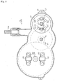
- FIG. 5 is an inner side view partly in section of a housing incorporating a hydraulic pump for the transaxle apparatuses.
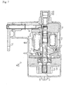
- FIG. 6 is a plan view partly in section of a structure which is common to the front and rear transaxle apparatuses 10 and 20 according to the invention.
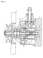
- FIG. 7 is a side view partly in section of a hydraulic motor integrally assembled in each of the transaxle apparatuses.
- FIG. 8 is a side view partly in section of the axle drive apparatus.
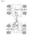
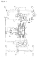
- FIG. 9 is a hydraulic circuit diagram including two hydraulic motors connected in series.
- FIG. 10 is a hydraulic circuit diagram including two hydraulic motors connected in series according to another example.
- FIG. 11 is a hydraulic circuit diagram including two hydraulic motors connected in parallel.
- FIG. 1 shows the riding lawn mower equipped at a front portion thereof with a mower device 3 serving as a working device.
- a front transaxle apparatus 10 is arranged on a front frame 11, and front wheels 13 are fixed to respective front wheel axles 12L and 12R extended laterally from the front transaxle apparatus 10.
- a rear transaxle apparatus 20 is arranged to a rear frame 21, and rear wheels 23 are fixed to respective rear wheel axles 22L and 22R extended laterally from the rear transaxle apparatus 20.
- a rear end part of the front frame 11 and a front end of the rear frame 21 are horizontally rotatably coupled to each other so that the rear frame 21 can be laterally folded relative to the front frame 11, thereby constituting an articulate vehicle serving as the riding lawn mower.
- An engine 5 is carried in rear frame 21.
- On the front frame 11 are arranged a steering column 14, a steering wheel 4, a pedal 15, and a seat 9 behind the steering column 14, thereby constituting an operation part 16.
- the mower device 3 driven by the engine 5 is vertically movably disposed downwardly forward from the operation part 16, i.e., at a distal end of the front frame 11 with respect to the vehicle.
- the rear transaxle apparatus 20 is arranged under the engine 5.
- the rear transaxle apparatus 20 and the front transaxle apparatus 10 are disposed mutually symmetrically with respect to a rotation center of the coupling part 50. More specifically, the front and rear transaxle apparatuses 10 and 20 are identical with each other in shape, and distributed into one side and the other in a lateral direction of the vehicle.
- the front transaxle apparatus 10 is arranged leftwardly eccentrically on the front wheel axles 12L and 12R, and the rear transaxle apparatus 20 is arranged rightwardly eccentrically on the rear wheel axles 22L and 22R.
- the front and rear transaxle apparatuses 10 and 20 may be distributed conversely in right and left.
- Each of the front transaxle apparatus 10 and the rear transaxle apparatus 20 has a common structure according to an embodiment shown in FIG. 6 , in which a hydraulic motor 40 is integrally assembled so as to drive the front wheel axles 12L and 12R or the rear wheel axles 22L and 22R.
- a housing 70 which incorporates a hydraulic pump 30 is arranged on the rear frame 21, and a pump center section 61 is disposed in a lower portion of the housing 70.
- Motor center sections 62 shown in FIG. 6 which are arranged in the front and rear transaxle apparatuses 10 and 20 respectively, are fluidly connected to the pump center section 61 shown in FIG. 5 through a distributor 80 arranged on the rear frame 21 and hydraulic hoses 81a, 81b and etc., as shown in FIG. 2 .
- the housing 70 and the distributor 80 may be arranged on the front frame 11.
- an engine output pulley 94 is fixed to an output shaft 93 of the engine 5
- an HST input pulley 92 is fixed to a pump shaft 31 of the hydraulic pump 30 incorporated in the housing 70
- an idle roller 96 is rotatably supported through a bearing (not shown) by a support shaft 95 hung from the rear frame 21.
- a working device driving power input pulley 111 is fixed to an input shaft 112 of the mower device 3 serving as a working device, and an idle pulley 98 is rotatably supported through a bearing (not shown) by a support shaft 97 hung from the front frame 11.
- a cylindrical pivotal coupler 28 which supports a vertical coupling shaft 55 unrotatably is disposed on a laterally middle front end portion of the rear frame 21.
- a platy pivotal coupler 18, U-like shaped in side view is disposed on a laterally middle rear end portion of the front frame 11. The coupler 18 is pivotally fitted onto the coupling shaft 55 so as to couple the front and rear frames 11 and 21 to each other, whereby the rear frame 21 can be laterally folded relative to the front frame 11.
- couplers 18 and 28 are disposed on respective proximal ends of the front and rear frames 11 and 21 with respect to the vehicle, and are coupled to each other through the coupling shaft 55 so as to constitute the coupling part 50.
- both the front and rear frames are coupled so as to be rotatable around the vertical axis of the coupling shaft 55 relative to each other by steering operation (of the steering wheel 4).
- a lower portion of the coupling shaft 55 is extended below so as to be rotatably provided thereon with mutually connected input and output pulleys 56 and 57 through bearings (not shown).
- a first working-device drive transmission belt 58 around the engine output pulley 94, the HST input pulley 92, the idle roller 96, and the input pulley 56.
- a second working-device drive transmission belt 59 around an idle roller 98, a working-device driving power input pulley 111, and the output pulley 57.
- engine output power is transmitted to the input pulley 56 through the first working-device drive transmission belt 58 from the engine output pulley 94, thereby rotating the output pulley 57 integrally with the input pulley 56 so as to transmit the power to the working-device driving power input pulley 111 through the second working-device drive transmission belt 59, and thereby rotating the input shaft 112 so as to rotate mowing blades 17.
- the right front wheel axle 12R is longer than the left front wheel axle 12L so that the front transaxle apparatus 10 extending the axles 12L and 12R is settled at the position shifted leftward from the lateral middle of the front frame 11.
- a pair of left and right collars 99a and 99b freely rotatably independently of each other.
- the second working-device drive transmission belt 59 is allowed to contact at undersurfaces thereof with the respective upper surfaces of the collars 99a and 99b.
- the front transaxle apparatus 10 supports the pair of axles having different lengths, and the second working-device drive transmission belt 59, i.e., the transmission element for drivingly connecting the engine 5 to the mower device 3 serving as a working device crosses the longer axle of the pair of axles and is allowed to contact the longer axle.
- the second working-device drive transmission belt 59 i.e., the transmission element for drivingly connecting the engine 5 to the mower device 3 serving as a working device crosses the longer axle of the pair of axles and is allowed to contact the longer axle.
- the second working-device drive transmission belt 59 passes through a position higher than the front wheel axle 12R, thereby ensuring a road clearance. Moreover, when the working device 3 is lowered for mowing, the second working-device drive transmission belt 59 is also lowered to the front wheel axle 12R and contacts the collars 99a and 99b. The collars 99a and 99b follow the belt 59 so as to rotate freely relative to the axle 12R while the belt 59 is prevented from directly contacting the axle 12R. Thus, the belt 59 is safe from being damaged by friction.
- the front transaxle apparatus 10 may be placed rightwardly eccentrically in the front frame 11.
- the rear transaxle apparatus 20 is shifted leftward so as to keep the symmetrical relation of the apparatuses 10 and 20.
- the HST hydraulic pump 30 is disposed in the inside of the housing 70 serving as a fluid sump.
- the HST hydraulic pump 30 comprises a cylinder block 33 slidably rotatably mounted on an upper pump mounting surface of the pump center section 60.
- Pistons 32 are reciprocally movably fitted through biasing springs into a plurality of cylinder bores in cylinder block 33.
- a thrust bearing 34a of a movable swash plate 34 abuts against heads of the pistons 32.
- An opening 34b is provided at the center of movable swash plate 34 so as to let a pump shaft 31 perforate therethrough.
- a control arm 38 engages with a side surface of the movable swash plate 34, so that the tilt angle of the movable swash plate 34 is adjusted by rotating a control shaft 37 serving as a rotary shaft of the control arm 38.
- the pump shaft 31 may function as an input shaft and be disposed vertically along the rotary axis of the cylinder block 33, the pump shaft 31 is rotatably supported by a bearing 35 fitted in an opening 36 formed an upper portion of the housing 70, and is not-relatively rotatably engaged with the cylinder block 33.
- an axial piston type variable displacement hydraulic pump 30 is constructed in the housing 70.
- the pump shaft 31 projects outwardly at the upper end thereof from the upper portion of the housing 70.
- An HST input pulley 92 with a cooling fan 91 below, is fixed onto the upper projecting portion of the pump shaft 31.
- the HST input pulley 92 receives power from the engine through transmission means so as to rotate the pump shaft 31.
- kidney-ports 61a and 61b Within the pump center section 61 are bored a pair of kidney-ports 61a and 61b from the upper pump mounting surface, and a pair of horizontal first and second fluid passages 51a and 51b.
- the kidney-port 61a is connected to the first fluid passage 51a, and the kidney-port 61b to the second fluid passage 51b.
- Each of the first and second fluid passages 51a and 51b is outwardly open at one end thereof and connected to a connection port (not shown) to be connected to a hydraulic hose.
- a feeding-and-discharging port 70a is formed in the upper portion of the housing 70 so as to ensure feeding and discharging of hydraulic fluid between a reservoir tank (not shown) and the fluid sump in the housing 70.
- the front transaxle apparatus 10 comprises a vertically separable housing formed by joining an upper housing half 46 and a lower housing half 47 through their open surfaces.
- the housing incorporates a hydraulic motor, etc.
- an inner space of the housing is divided into first and second chambers 10a and 10b.
- a differential gearing 120 is disposed in the first chamber 10a, and a hydraulic motor 40 in the second chamber 10b.
- the driving power of the hydraulic motor 40 is transmitted to the differential gearing 120 through a two-stepped deceleration gear train 135.
- the hydraulic motor 40 which comprises a motor center section 62 and a cylinder block 43 slidably rotatably mounted onto a motor mounting surface 63 m formed on a vertical portion of the motor center section 62.
- a plurality of pistons 42 are reciprocally movably fitted into a plurality of cylinder bores in cylinder block 43 through respective biasing springs. Heads of the pistons 42 abut against a thrust bearing 44a of a fixed swash plate 44 which is fixedly sandwiched between upper housing half 46 and lower housing half 47.
- An opening 44b is provided in the center of the fixed swash plate 44 so as to let the motor shaft 41 perforate therethrough.
- the motor shaft 41 may function as an output shaft and be disposed horizontally along the rotary axis of the cylinder block 43, the motor shaft 41 is rotatably supported by a bearing 45 held on the joint surface between the upper and lower housing halves 46 and 47, and is not-relatively rotatably engaged with the cylinder block 43.
- an axial piston type fixed displacement hydraulic motor 40 is constructed in the front transaxle apparatus 10.
- kidney-ports 62a and 62b within the motor center section 62 are bored a pair of kidney-ports 62a and 62b from the vertical motor mounting surface 63m, and a pair of horizontal first and second fluid passages 53a and 53b.
- the kidney-port 62a is connected to the first fluid passage 53a, and the kidney-port 62b to the second fluid passage 53b.
- the first fluid passage 53a is connected to a cap 54a, and the second fluid passage 53b to a cap 54b.
- Hydraulic hoses are connected to the respective caps 54a and 54b so as to fluidly connect the hydraulic motor 40 to the hydraulic pump 30.
- a bypass operation lever 65 for opening the first and second fluid passages 53a and 53b to the fluid sump is disposed above the upper housing half 46.
- the bypass operation lever 65 is fixed at a basal portion thereof to an upper end of a vertical bypass lever shaft 66 rotatably supported by an upper wall of the upper housing half 46.
- the lower end of the bypass lever shaft 66 is extended into the motor center section 62 so as to be horizontally slidable against the motor center section 62.
- a thrust pin 67 is provided and allowed to abut against the rotationally sliding surface of the cylinder block 43.
- the thrust pin 67 is also allowed to contact at an end surface thereof with a flat surface 66a formed by cutting away a bottom side portion of the bypass lever shaft 66.
- a feeding-and-discharging port 46a is formed in an upper portion of the upper housing half 46 so as to let hydraulic fluid flow between the transaxle apparatus and a reservoir tank ( FIG. 9 ), thereby regulating the volume of hydraulic fluid in the transaxle apparatus.
- a drive output gear 131 on an end portion of the motor shaft 41 opposite to the motor center section 62 is spline-fitted a drive output gear 131 so that the drive output gear 131 rotates together with the motor shaft 41.
- the drive output gear 131 is integrally formed at a side toward the motor center section 62 with a brake rotor 133 whose diameter is larger than that of drive output gear 131.
- the rotating motor shaft 41 is braked when the brake rotor 133 is pressed between brake pads 134a and 134b ( FIG. 6 ).
- a counter shaft 139 is arranged in parallel to the motor shaft 41.
- a wide small diameter gear 137 is fitted loosely on the counter axis 139, and a large diameter gear 136 is fitted onto a tooted side of the small diameter gear 137, thereby constituting the deceleration gear train 135.
- the small diameter gear 137 engages with a ring gear 121 of the differential gearing 120 so that driving force of the motor shaft 41 is transmitted to the differential gearing 120 through the deceleration gear train 135.
- the differential gearing 120 comprises a ring gear 121 which engages with the small diameter gear 137, pinions 123 rotatably supported by respective pinion shafts 122 which project inward from an inner periphery of the ring gear 121, and side gears 124 fixed onto the respective front wheel axles 12L and 12R and engaging with each of the pinions 123.
- the driving force of the motor shaft 41 is transmitted to the front wheel axles 12L and 12R through the intermediate gearing 135, the ring gear 121, the pinions 123 and the side gears 124.
- the differential gearing 120 may be provided with a differential-lock system so that, even when one of the wheels is bogged in mud etc., the vehicle can escape easily.
- transaxle apparatus is common to the front and rear transaxle apparatuses 10 and 20, thereby contributing for standardization of component parts so as to reduce costs for manufacture and care.
- the fluid distributor 80 is fluidly connected to the connection port of the center section in housing 70 through hydraulic hoses 81a and 81b, and also fluidly connected to the center section in the front transaxle apparatus 10 through hydraulic hoses 81c and 81d, and to the center section in the rear transaxle apparatus 20 through hydraulic hoses 81e and 81f.
- Hydraulic fluid discharged from the hydraulic pump 30 which is drivingly connected with the engine is supplied to the front transaxle apparatus 10 and the rear transaxle apparatus 20 through the fluid distributor 80 so as to rotate the hydraulic motors in both the transaxle apparatuses 10 and 20, thereby driving the front wheel axles 12L and 12R, and the rear wheel axles 22L and 22R, respectively.
- the fluid distributor 80 fluidly connects a hydraulic circuit of the hydraulic pump 30 in the housing 70 to hydraulic circuits of the front transaxle apparatus 10 and the rear transaxle apparatus 20.
- Two styles as a hydraulic circuit of the fluid distributor 80 are provided for the fluidal connection among the hydraulic motor 30 and the front and rear transaxle apparatuses 10 and 20.
- One is a fluid distributor 80a to connect the hydraulic motor 40a a hydraulic motor 40a in the front transaxle apparatus 10 and a hydraulic motor 40b in the rear transaxle apparatus 20 fluidly in series through a control valve 85a, as shown in FIGS. 9 and 10 .
- the other is a fluid distributor 80b to connect the hydraulic motor 40a a hydraulic motor 40a in the front transaxle apparatus 10 and a hydraulic motor 40b in the rear transaxle apparatus 20 fluidly in parallel through a control valve 85b, as shown in FIG. 11 .
- the fluid distributor 80a shown in FIG. 9 fluidly connects both the hydraulic motors 40a and 40b in series.
- the series connection is applicable to an articulate vehicle whose coupling part 50 is arranged at the longitudinally middle position of the vehicle and serves as the center of left and right turning of the vehicle.
- this circuit is effective to a vehicle which generates no or little (tolerant) rotary speed difference between the front wheels at the time of left or right turning of the vehicle.
- first, second and third fluid passages 82a, 82b and 82c are formed in the fluid distributor 80.
- the first fluid passage 82a connects a connection port 83a for the hydraulic hose 81a and a connection port 83c for the hydraulic hose 81c through the control valve 85a.
- the second fluid passage 82b connects a connection port 83d for the hydraulic hose 81d and a connection port 83e for the hydraulic hose 81e through the control valve 85a.
- the third fluid passage 82c connects a connection port 83f for the hydraulic hose 81f and a connection port 83b for the hydraulic hose 81b.
- the control valve 85a is a directive control valve having four ports and two positions. At a first position of the control valve 85a, the first fluid passage 82a and the second fluid passage 82b are opened for free passage, respectively. At a second position of the control valve 85a, both the first fluid passage 82a and the second fluid passage 82b are closed, and free fluid passages are formed between the connection ports 83a and 83e, and between the connection ports 83c and 83d, respectively.
- hydraulic fluid discharged from the hydraulic pump 30 is supplied to the hydraulic motor 40a of the front transaxle apparatus 10, for example, through the hydraulic hose 81a, the first fluid passage 82a and the hydraulic hose 81b so as to drive the front wheel axles 12L and 12R.
- hydraulic fluid is supplied to the hydraulic motor 40b of the rear transaxle apparatus 20 through the hydraulic hose 81d, the second fluid passage 82b and the hydraulic hose 81e so as to drive the rear wheel axles 22L and 22R, and is inhaled into the hydraulic pump 30 through the hydraulic hose 81f, the third fluid passage 82c and the hydraulic hose 81b.
- the vehicle drives four wheels, in which the front transaxle apparatus 10 drives the front wheel axles 12L and 12R, and the rear transaxle apparatus 20 the rear wheel axles 22L and 22R, thereby being excellent in traveling on a bad ground or ascent.
- the four-wheel drive vehicle employing the fluid circuit with the series connection is excellent in escaping performance at the time of a wheel being bogged in mud.
- hydraulic fluid discharged from the hydraulic pump 30 flows to the hydraulic motor 40a of the front transaxle apparatus 10 so as to idle the unloaded front wheels, and then flows to the hydraulic motor 40b of the rear transaxle apparatus 20 so as to rotate the loaded rear wheels, too, whereby the vehicle can escape from mud smoothly with driving the rear wheels surely.
- control valve 85a when the control valve 85a is set at the second position, hydraulic fluid is not supplied to the hydraulic motor 40a of the front transaxle apparatus 10, that is, hydraulic fluid is supplied only to the hydraulic-motor 40b of the rear transaxle apparatus 20 so as to rotate only the rear wheel axles 22L and 22R, so that the vehicle drives only the rear wheels, thereby being excellent in steering performance.
- control valve 81 may be changed the connection form among the hydraulic hoses 81c, 81d, 81e and 81f. That is, the connection ports 83c and 83d may be connected to the hydraulic motor 40b on the rear frame 21, and the connection ports 83e and 83f to the hydraulic motor 40a on the front frame 11, thereby establishing the vehicle into a front-wheel drive mode, where the vehicle drives only the front wheel axles 12L and 12R and is excellent in steering performance.
- connection ports 83c and 83d may be connected to each other through a hydraulic hose so as to bypass the hydraulic motor 40a, or the connection ports 83e and 83f may be connected to each other through a hydraulic hose so as to bypass the hydraulic motor 40b, so that the control valve 85a is fixed to the first position without being switched to the second position, thereby making either a front-wheel drive vehicle or a rear-wheel drive vehicle.
- a swash plates 144a of the hydraulic motor 40a is movable and a control arm 144b for adjusting the tilt angle of the swash plate 144a is interlockingly connected to the steering wheel 4 through a wire, a link or so on, thereby changing the swash plate angle according to the angle of the steering wheel 4 so as to increase the rotary speed of the front wheel axles.
- This composition is especially effective to improve steering performance of a vehicle whose body is arranged so as not to generate a rotary speed difference between the front wheels and the rear wheels when the vehicle turns, i.e., a vehicle whose coupling part 50 is not disposed at the longitudinally middle position of the vehicle, or a four-wheel drive riding lawn mower in which the front wheels are steered by an Ackerman steering system as shown in FIG. 10 .
- the hydraulic motor for driving steerable (front) wheels into a variable displacement type and increasing the rotary speed of the hydraulic motor in correspondent to the angle of the steering wheel, improved steering performance can be provided for a vehicle such as the riding lawn mower, which has such a body arrangement as to generate a rotary speed difference between the front wheels and the rear wheels at the time of turning of the vehicle, and in which both the hydraulic motors in front and rear transaxle apparatuses are fluidly connected in series.
- the fluid distributor 80b shown in FIG. 11 fluidly connects both the hydraulic motors 40a in parallel.
- This parallel connection style is especially applicable to a vehicle which turns with a rotary speed difference between front wheels and rear wheels.
- first, second, third and fourth fluid passages 84a, 84b, 84c and 84d are formed in the fluid distributor 80.
- the first fluid passage 84a connects a connection port 83c for the hydraulic hose 81c and a connection port 83f for the hydraulic hose 81f through a control valve 85b.
- the second fluid passage 84b connects a connection port 83d for the hydraulic hose 81d and a connection port 83e for the hydraulic hose 81e through the control valve 85b.
- the third fluid passage 84c connects the first fluid passage 84a to a connection port 83a for the hydraulic hose 81a.
- the fourth fluid passage 84d connects the second fluid passage 84b to a connection port 83b for the hydraulic hose 81b.
- the control valve 85b is a directive control valve having four ports and two positions. At the first position of the control valve 85b, the first fluid passage 84a and the second fluid passage 84b are opened for free passage respectively. At the second position of the control valve 84b, the first fluid passage 84a and the second fluid passage 84b are closed, and a free fluid passage is formed between the connection port 83c and the connection port 83d.
- hydraulic fluid discharged from the hydraulic pump 30 is supplied to the hydraulic motors 40a and 40b of the front and rear transaxle apparatuses 10 and 20, for example, through the hydraulic hose 81a, the third fluid passage 84c, the first fluid passage 82a, and the hydraulic hoses 81c and 81f, respectively, so as to drive the front and rear wheel axles 12L, 12R, 22L and 22R.
- hydraulic fluid discharged from the hydraulic motors 40a and 40b is inhaled into the hydraulic pump 30 through the respective hydraulic hoses 81d and 81e, the second fluid passage 84b, the fourth fluid passage 84b, and the hydraulic hose 81b.
- both the front transaxle apparatus 10 and the rear transaxle apparatus 20 drive the front wheel axles 12L and 12R, and the rear wheels axle 22L and 22R, respectively, so that the vehicle drives four wheels and is excellent in steering performance and traveling performance on a bad ground or ascent.
- control valve 85b when the control valve 85b is set at the second position, hydraulic fluid is not supplied to the hydraulic motor 40a of the front transaxle apparatus 10, that is, hydraulic fluid is supplied only to the hydraulic motor 40b of the rear transaxle apparatus 20 so as to drive only the rear wheel axles 22L and 22R, whereby the vehicle drives only the rear wheels and is excellent in steering performance.
- control valve 85b may be changed the connection form among the hydraulic hoses 81c, 81d, 81e and 81f. That is, the connection ports 83c and 83d may be connected to the hydraulic motor 40b on the rear frame 21, and the connection ports 83e and 83f to the hydraulic motor 40a on the front frame 11, thereby establishing the vehicle into a front-wheel drive mode, where the vehicle drives only the front wheel axles 12L and 12R and is excellent in steering performance.
- a rear-wheel drive vehicle may be made by plugging the connection ports 83c and 83d and holding the control valve 85a at the first position without shifting it to the second position.
- the differential gearings 120 of the front and rear transaxle apparatuses 10 and 20 are provided with respective differential-lock systems 125 for restricting the differential rotation of the respective left and right axles, and the vehicle is provided with a control lever for controlling the differential-lock systems 125.
- the vehicle is so designed that the differential rotation of the axles is restrained when a wheel is stuck.
- hydraulic fluid is divided between the two hydraulic motors 40a and 40b, thereby causing such a problem that a larger amount of hydraulic fluid slows into a lighter-loaded hydraulic motor of the two. If a right front wheel driven by the front hydraulic motor 40b is stuck, for example, the rear hydraulic motor 40b is not supplied with hydraulic fluid and the rear wheels do not drive, whereby the vehicle cannot escape from being bogged.
- the position of the control valve 85a or 85b may be decided so as to select the driving style of the vehicle between the four-wheel drive and the rear-wheel drive.
- the driving style of the vehicle may be selected before shipment from a factory.
- the vehicle may be provided with an operation lever for switching the position of the control valve 85a or 85b so that a driver can optionally operate the lever so as to select the driving mode of the vehicle between the four-wheel drive mode and the two-wheel drive mode (rear-wheel drive mode or front-wheel drive mode) even when the vehicle travels.
- the present invention constructed as described above has the following effects.
- a drive train comprising each transaxle apparatus and its corresponding hydraulic motor can be compact.
Landscapes
- Engineering & Computer Science (AREA)
- Mechanical Engineering (AREA)
- General Engineering & Computer Science (AREA)
- Chemical & Material Sciences (AREA)
- Combustion & Propulsion (AREA)
- Transportation (AREA)
- Life Sciences & Earth Sciences (AREA)
- Environmental Sciences (AREA)
- Physics & Mathematics (AREA)
- Fluid Mechanics (AREA)
- Motor Power Transmission Devices (AREA)
- Arrangement And Driving Of Transmission Devices (AREA)
Claims (6)
- Appareil formant boîte-pont (10 ; 20) comprenant :un essieu (12L, 12R ; 22L, 22R) ayant un axe ;un boîtier (46, 47) supportant l'essieu (12L, 12R ; 22L, 22R), dans lequel le boîtier (46, 47) inclut un premier organe de boîtier (46) et un second organe de boîtier (47) qui sont joints l'un à l'autre par l'intermédiaire d'une surface de jonction le long de l'axe de l'essieu (12L, 12R ; 22L, 22R) ;un moteur hydraulique à déplacement fixe de type piston axial (40) disposé dans le boîtier (46, 47), dans lequel le moteur hydraulique (40) inclut un bloc-cylindres (43) et un arbre de moteur (41) mis en prise sur le bloc-cylindres (43) et s'étendant parallèlement à l'axe de l'essieu (12L, 12R ; 22L, 22R) ;une section centre moteur (62) disposée dans le boîtier (46, 47) et contenant une paire de lumières réniformes (62a, 62b) raccordée par fluide au bloc-cylindres (43) ; etun train d'engrenages de décélération à deux pas (135) disposé dans le boîtier (46, 47) de façon à raccorder en propulsion l'arbre de moteur (41) à l'essieu (12L, 12R ; 22L, 22R) ;caractérisé en ce queune paire de capuchons (54a, 54b) est disposée dans le boîtier (46, 47) et est raccordée par fluide au bloc-cylindres (43), dans lequel les capuchons (54a, 54b) sont raccordés directement à la section centre moteur (62) de façon à être raccordés par fluide aux lumières réniformes (62a, 62b) respectives, et est prolongée et ouverte vers l'extérieur depuis le boîtier (46, 47) de façon à recevoir et délivrer un fluide depuis et à une pompe hydraulique (30) disposée séparée de et à l'extérieur du boîtier (46, 47).
- Appareil formant boîte-pont (10 ; 20) selon la revendication 1, dans lequel la section centre moteur (62) contenant les lumières réniformes (62a, 62b) est une plaque plate qui est fixée de manière séparable dans le boîtier (46, 47) de façon à être disposée adjacente à une surface intérieure d'une paroi latérale du boîtier (46, 47), dans lequel la section centre moteur (46) a des première et seconde surfaces opposées l'une à l'autre, la première surface étant distante de la surface intérieure de la paroi latérale du boîtier (46, 47) et la seconde surface étant adjacente à la surface intérieure de la paroi latérale du boîtier (46, 47), dans lequel la première surface de la section centre moteur (62) inclut une surface de montage de moteur (63m) sur laquelle le bloc-cylindres (43) est monté, les lumières réniformes (62a, 62b) étant ouvertes dans la surface de montage de moteur (63m), et dans lequel la paire de capuchons (54a, 54b) fait saillie vers l'extérieur depuis la seconde surface de la section centre moteur (62) et pénètre la paroi latérale du boîtier (46, 47) de façon à s'étendre et à être ouverte vers l'extérieur depuis le boîtier (46, 47).
- Appareil formant boîte-pont (10 ; 20) selon la revendication 2, dans lequel la paire de capuchons (54a, 54b) est vissée à travers la paroi latérale du boîtier (46, 47) de façon à être ajustée de façon séparable dans la section centre moteur (62) par l'intermédiaire de la seconde surface de la section centre moteur (62) et de façon à être raccordée par fluide au bloc-cylindres (43).
- Appareil formant boîte-pont (10 ; 20) selon la revendication 1, 2 ou 3, dans lequel la section centre moteur (62) est pourvue d'un système de contournement (66, 67) qui est opérationnel à l'extérieur du boîtier (46, 47) de façon à purger un fluide depuis le bloc-cylindres (43) vers un collecteur de fluide dans le boîtier (46, 47).
- Appareil formant boîte-pont (10 ; 20) selon l'une quelconque des revendications 1 à 4, dans lequel lesdits capuchons (54a, 54b) sont formés de façon à permettre un raccordement par fluide avec des tuyaux hydrauliques.
- Appareil formant boîte-pont (10 ; 20) selon l'une quelconque des revendications 1 à 5, dans lequel le moteur hydraulique (40) inclut un plateau oscillant (44) qui est intercalé entre le premier et un second organe de boîtier (46, 47) de façon à être fixé dans le boîtier (46, 47).
Applications Claiming Priority (2)
| Application Number | Priority Date | Filing Date | Title |
|---|---|---|---|
| US10/277,115 US6732828B1 (en) | 2002-10-22 | 2002-10-22 | Hydraulically driven vehicle |
| EP03006402A EP1415849B1 (fr) | 2002-10-22 | 2003-03-20 | Véhicule à propulsion hydraulique |
Related Parent Applications (2)
| Application Number | Title | Priority Date | Filing Date |
|---|---|---|---|
| EP03006402.6 Division | 2003-03-20 | ||
| EP03006402A Division EP1415849B1 (fr) | 2002-10-22 | 2003-03-20 | Véhicule à propulsion hydraulique |
Publications (3)
| Publication Number | Publication Date |
|---|---|
| EP2048020A2 EP2048020A2 (fr) | 2009-04-15 |
| EP2048020A3 EP2048020A3 (fr) | 2009-05-06 |
| EP2048020B1 true EP2048020B1 (fr) | 2012-12-12 |
Family
ID=32069305
Family Applications (3)
| Application Number | Title | Priority Date | Filing Date |
|---|---|---|---|
| EP09152055A Expired - Lifetime EP2048020B1 (fr) | 2002-10-22 | 2003-03-20 | Véhicule à propulsion hydraulique |
| EP03006402A Expired - Lifetime EP1415849B1 (fr) | 2002-10-22 | 2003-03-20 | Véhicule à propulsion hydraulique |
| EP03023896A Expired - Lifetime EP1413498B1 (fr) | 2002-10-22 | 2003-10-21 | Véhicule à quatre roues motrices |
Family Applications After (2)
| Application Number | Title | Priority Date | Filing Date |
|---|---|---|---|
| EP03006402A Expired - Lifetime EP1415849B1 (fr) | 2002-10-22 | 2003-03-20 | Véhicule à propulsion hydraulique |
| EP03023896A Expired - Lifetime EP1413498B1 (fr) | 2002-10-22 | 2003-10-21 | Véhicule à quatre roues motrices |
Country Status (3)
| Country | Link |
|---|---|
| US (5) | US6732828B1 (fr) |
| EP (3) | EP2048020B1 (fr) |
| DE (2) | DE60327733D1 (fr) |
Families Citing this family (72)
| Publication number | Priority date | Publication date | Assignee | Title |
|---|---|---|---|---|
| US7455144B2 (en) * | 2002-10-15 | 2008-11-25 | Kanzaki Kokyukoki Mfg. Co., Ltd. | Hydraulic transaxle apparatus with flexible ports |
| US6845837B2 (en) * | 2002-10-15 | 2005-01-25 | Kanzaki Kokyukoki Mfg. Co., Ltd. | Hydraulic transaxle apparatus for a four-wheel driving vehicle and four-wheel driving vehicle using the apparatus |
| US7896123B2 (en) * | 2002-10-15 | 2011-03-01 | Kanzaki Kokyukoki Mfg. Co., Ltd. | Hydraulic drive vehicle |
| US7363759B2 (en) * | 2002-10-15 | 2008-04-29 | Kanzaki Kokyukoki Mfg. Co., Ltd. | Hydraulic transaxle apparatus for a four-wheel-drive vehicle and four-wheel-drive vehicle using the apparatus |
| US6732828B1 (en) * | 2002-10-22 | 2004-05-11 | Robert Abend | Hydraulically driven vehicle |
| US7540349B2 (en) * | 2002-10-29 | 2009-06-02 | Kanzaki Kokyukoki Mfg. Co., Ltd. | Transaxle apparatus for four-wheel drive vehicle |
| US6902017B2 (en) * | 2002-10-29 | 2005-06-07 | Ryota Ohashi | Transaxle apparatus and four-wheel driving working vehicle using the apparatus |
| US7204779B2 (en) * | 2003-09-26 | 2007-04-17 | Koji Irikura | Hydraulic steering transaxle and hydraulic driving vehicle |
| JP2005153703A (ja) * | 2003-11-26 | 2005-06-16 | Kanzaki Kokyukoki Mfg Co Ltd | 胴体屈折型の油圧駆動式四輪駆動車両 |
| EP1541402B1 (fr) * | 2003-12-11 | 2008-04-02 | Kanzaki Kokyukoki Mfg. Co., Ltd. | Essieu hydraulique et véhicule comprenant ledit essieu |
| EP1586775A3 (fr) * | 2004-04-13 | 2011-11-09 | Kanzaki Kokyukoki Mfg. Co., Ltd. | Dispositif de vidange pour système d'entraînement hydraulique |
| US7377353B2 (en) * | 2004-07-29 | 2008-05-27 | Sauer-Danfoss Inc. | Four wheel traction control valve system |
| US7383913B1 (en) * | 2004-09-02 | 2008-06-10 | Kanzaki Kokyukoki Mfg. Co., Ltd. | Hydraulic transaxle and vehicle comprising it |
| US7082759B1 (en) * | 2004-09-02 | 2006-08-01 | Michio Tsukamoto | Hydraulic drive vehicle |
| JP5097883B2 (ja) * | 2004-09-02 | 2012-12-12 | 株式会社 神崎高級工機製作所 | 油圧駆動車両 |
| DE202004013887U1 (de) * | 2004-09-03 | 2006-01-12 | Al-Ko Kober Ag | Aufsitzmäher |
| JP2006315655A (ja) | 2005-04-12 | 2006-11-24 | Kanzaki Kokyukoki Mfg Co Ltd | 油圧駆動式作業車両及び車軸駆動装置 |
| JP2006321339A (ja) * | 2005-05-18 | 2006-11-30 | Kanzaki Kokyukoki Mfg Co Ltd | 油圧駆動式作業車両の動力伝達機構 |
| US20080210482A1 (en) * | 2005-05-18 | 2008-09-04 | Norihiro Ishii | Hydraulic Drive Vehicle with Cooling System |
| US20090025997A1 (en) * | 2005-05-18 | 2009-01-29 | Norihiro Ishii | Hydraulic Drive Vehicle with Cooling System |
| JP2007050745A (ja) | 2005-08-17 | 2007-03-01 | Kanzaki Kokyukoki Mfg Co Ltd | 油圧駆動式車輌 |
| JP2007085405A (ja) * | 2005-09-20 | 2007-04-05 | Kobelco Cranes Co Ltd | 油圧駆動式作業車両の走行安定装置 |
| US7770685B2 (en) * | 2005-10-31 | 2010-08-10 | Deere & Company | Propulsion system for a work vehicle having a single drive pump and differential capability |
| DE602007005286D1 (de) * | 2006-01-16 | 2010-04-29 | Kanzaki Kokyukoki Mfg Co Ltd | Hydrostatische Treibachse |
| JP2008062691A (ja) * | 2006-09-05 | 2008-03-21 | Kanzaki Kokyukoki Mfg Co Ltd | 油圧駆動型作業車輌 |
| JP2008099557A (ja) * | 2006-09-19 | 2008-05-01 | Kanzaki Kokyukoki Mfg Co Ltd | 作業車輌の伝動構造 |
| KR101475522B1 (ko) * | 2007-06-25 | 2014-12-22 | 가부시끼 가이샤 구보다 | 작업차 |
| US7694772B1 (en) | 2007-08-03 | 2010-04-13 | M-B Companies Inc. | Forward cab articulated tractor |
| US20090098961A1 (en) * | 2007-10-12 | 2009-04-16 | Toshiyuki Hasegawa | Internal Combustion Engine, Vehicle Power Transmission System and Lawn Tractor Equipped With Them |
| EP2088023B1 (fr) * | 2008-02-06 | 2011-06-22 | Kanzaki Kokyukoki Mfg. Co., Ltd. | Agencement de transmission finale et véhicule avec un tel agencement |
| EP2174816B1 (fr) * | 2008-02-13 | 2012-06-06 | Kanzaki Kokyukoki Mfg. Co., Ltd. | Dispositif de moteur de roue |
| US8002073B2 (en) * | 2008-04-22 | 2011-08-23 | Kanzaki Kokyukoki Mfg. Co., Ltd. | Hydraulic drive working vehicle |
| JP2009262840A (ja) * | 2008-04-28 | 2009-11-12 | Kanzaki Kokyukoki Mfg Co Ltd | 油圧四輪駆動型作業車輌 |
| US7967099B2 (en) * | 2008-06-19 | 2011-06-28 | Caterpillar Paving Products Inc. | Method and arrangement of a plurality of propel pumps in a hydrostatically driven compactor |
| US9017052B1 (en) * | 2009-03-30 | 2015-04-28 | Harry Soderstrom | Positive displacement pump with improved rotor design |
| JP2010247586A (ja) * | 2009-04-13 | 2010-11-04 | Yamaha Motor Co Ltd | 車両 |
| EP2336606B1 (fr) | 2009-12-10 | 2014-05-07 | Kanzaki Kokyukoki Mfg. Co., Ltd. | Unité de moteur hydraulique et véhicule de travail à quatre roues motrices hydrauliques |
| JP5581479B2 (ja) | 2010-07-05 | 2014-09-03 | 株式会社 神崎高級工機製作所 | 油圧四輪駆動作業車輌 |
| US8579069B2 (en) * | 2010-12-23 | 2013-11-12 | Caterpillar Inc. | Forestry machines with transverse engine and hydraulic system installation |
| CN102326483B (zh) * | 2011-08-18 | 2013-07-31 | 覃志明 | 一种联合收割机的后轮液压驱动系统 |
| US9045014B1 (en) | 2012-03-26 | 2015-06-02 | Oshkosh Defense, Llc | Military vehicle |
| USD966958S1 (en) | 2011-09-27 | 2022-10-18 | Oshkosh Corporation | Grille element |
| CA2962238C (fr) | 2012-02-13 | 2017-12-05 | Husqvarna Ab | Tondeuse poussee a traction integrale |
| US20140199190A1 (en) * | 2013-01-11 | 2014-07-17 | Promanpto, Llc | Integrated Foot Pedal Control System for Hydraulic Power Take-Off Assembly for ATV |
| US9872434B2 (en) * | 2013-08-28 | 2018-01-23 | Husqvarna Ab | Articulated rider collection assembly |
| WO2015117962A1 (fr) | 2014-02-04 | 2015-08-13 | Dana Italia Spa | Fonction de déplacement et travail d'extraction intégrés dans un système hybride hydraulique |
| KR20160117484A (ko) | 2014-02-04 | 2016-10-10 | 다나 이탈리아 에스피에이 | 축압기 랙 |
| EP3102853B1 (fr) | 2014-02-04 | 2019-11-06 | DANA ITALIA S.p.A | Architecture hybride hydraulique série-parallèle |
| CN105960362B (zh) | 2014-02-04 | 2019-03-26 | 意大利德纳股份有限公司 | 利用串联型混合的混合动力模式 |
| WO2015117963A1 (fr) | 2014-02-04 | 2015-08-13 | Dana Italia Spa | Moyeu à accroissement de puissance |
| US9932028B2 (en) | 2014-02-04 | 2018-04-03 | Dana Italia Spa | Controller for a series hydraulic hybrid transmission |
| US9730386B1 (en) * | 2014-06-11 | 2017-08-15 | Charles Bradley Covington | Suspension system for lawnmower |
| US10188033B1 (en) | 2014-06-11 | 2019-01-29 | Bad Boy, Inc. | Suspension system for lawnmower |
| EP3002147A1 (fr) | 2014-10-02 | 2016-04-06 | Dana Italia S.p.A. | Transmission à double entraînement |
| CN104686083B (zh) * | 2014-10-27 | 2016-11-30 | 青岛科瑞特激光设备有限公司 | 收割机用两档四轮驱动液压无级变速驱动桥总成 |
| US9677648B2 (en) | 2015-01-14 | 2017-06-13 | The Toro Company | Walk-behind power equipment unit having all-wheel drive control system |
| US11261876B2 (en) * | 2016-04-14 | 2022-03-01 | Parker-Hannifin Corporation | Fan with integrated shaft guard |
| CN107097641B (zh) * | 2016-08-29 | 2024-05-03 | 襄阳群龙汽车部件股份有限公司 | 一种液压四轮驱动装置 |
| US10569609B1 (en) | 2016-09-19 | 2020-02-25 | Bad Boy, Inc. | Articulating front axle mower |
| EP3515169B1 (fr) * | 2016-09-21 | 2023-12-06 | MTD products Inc | Ensemble de commande pour tondeuse à gazon poussée |
| JP6869808B2 (ja) * | 2017-05-26 | 2021-05-12 | 株式会社クボタ | 作業機の制御装置、作業機の制御方法及び作業機 |
| CN107650678B (zh) * | 2017-09-22 | 2021-08-17 | 清华大学 | 分布式纯电动车的底盘系统 |
| DE102017131133B4 (de) * | 2017-12-22 | 2019-08-14 | Hubtex Maschinenbau Gmbh & Co. Kg | Betriebsverfahren eines personengesteuerten Flurförderzeugs und Flurförderzeug |
| JP7055713B2 (ja) * | 2018-07-10 | 2022-04-18 | 株式会社クボタ | 作業機 |
| CN109130849A (zh) * | 2018-10-17 | 2019-01-04 | 泰安九洲金城机械有限公司 | 一种微型铰接转向装载机传动系统 |
| CA3129592A1 (fr) * | 2019-02-22 | 2020-08-27 | Clark Equipment Company | Commande de traction pour machine d'assistance de direction articulee |
| US11178812B1 (en) | 2019-08-19 | 2021-11-23 | Bad Boy Mowers, Llc | Stand-on mower folding platform system |
| US11178815B1 (en) | 2019-08-19 | 2021-11-23 | Bad Boy Mowers, Llc | Stand-on mower intermediate pulley system |
| US10953715B1 (en) | 2019-09-19 | 2021-03-23 | Bad Boy Mowers, Llc | Riding mower trailing arm suspension system |
| CN110771287A (zh) * | 2019-11-11 | 2020-02-11 | 常州格力博有限公司 | 一种园林工具 |
| CN112576718A (zh) * | 2020-11-04 | 2021-03-30 | 东风越野车有限公司 | 一种大功率全时分动器差速机构及车辆 |
| US20220192095A1 (en) * | 2020-12-21 | 2022-06-23 | Honda Motor Co., Ltd. | Mower propulsion apparatus including a split transaxle |
Family Cites Families (36)
| Publication number | Priority date | Publication date | Assignee | Title |
|---|---|---|---|---|
| US189251A (en) * | 1877-04-03 | Improvement in bird-cages | ||
| US1187A (en) * | 1839-06-24 | Corn-sheller and machine for hulling grain | ||
| US3151694A (en) * | 1961-05-11 | 1964-10-06 | Clark Equipment Co | Steering arrangement and hydrostatic drive for articulated vehicle |
| US3342282A (en) * | 1965-06-14 | 1967-09-19 | Harper Mfg Inc | Hydraulically driven articulated vehicle |
| DE6804828U (de) * | 1967-11-07 | 1969-03-06 | Deere & Co | Gartenschlepper mit zwischen den achsen angeordnetem geraet |
| US3865208A (en) * | 1973-05-21 | 1975-02-11 | Canadian Mine Services Ltd | Hydraulic drive apparatus for wheeled vehicle |
| US4042053A (en) * | 1974-12-24 | 1977-08-16 | Allis-Chalmers Corporation | Four-wheel drive tractor |
| FI77192C (sv) * | 1980-03-10 | 1989-02-10 | Konetehdas Norcar | Hydraulmotordrivet tvådelat terränggående fordon |
| SE454127B (sv) * | 1985-08-08 | 1988-04-11 | Husqvarna Ab | Akbar gresklippare |
| JPS62198570A (ja) * | 1986-02-24 | 1987-09-02 | Kubota Ltd | 車体折れ車輌 |
| DE3620163A1 (de) * | 1986-06-14 | 1987-12-17 | Sauer Getriebe Ag | Verfahren zur steuerung oder reglung eines hydrostatischen antriebs ueber die vorderraeder eines fahrzeugs mit mechanischem, hydrodynamischem oder hydrostatischem getriebe und verbrennungskolbenmotor als heckantrieb und anordnung zur durchfuehrung des verfahrens |
| DE3638665A1 (de) * | 1986-11-12 | 1988-05-19 | Bosch Gmbh Robert | Antiblockierregelsystem |
| US4926970A (en) * | 1987-04-10 | 1990-05-22 | Ingersoll-Rand Company | Lube oil system for rotating machinery |
| US4886142A (en) * | 1987-06-26 | 1989-12-12 | Kanzaki Kokyukoki Mfg. Co. Ltd. | Hydraulic four-wheel drive system |
| US4947956A (en) * | 1987-10-13 | 1990-08-14 | Clark Equipment Company | Hydrostatic transmissions system for an articulated vehicle |
| JPH0771895B2 (ja) * | 1988-02-03 | 1995-08-02 | 株式会社神崎高級工機製作所 | 車軸駆動装置 |
| US4932209A (en) * | 1988-02-03 | 1990-06-12 | Kanzaki Kokyukoki Mf. Co. Ltd. | Axle driving apparatus |
| US4914898A (en) * | 1989-04-27 | 1990-04-10 | Deere & Company | V-belt guide |
| DE9107488U1 (de) * | 1991-06-18 | 1991-08-29 | Hartig, Jürgen, 3402 Niemetal | Radfahrzeug, insbesondere Forstmaschine |
| US5361566A (en) * | 1993-05-05 | 1994-11-08 | Deere & Company | Implement belt drive mechanism |
| US6125630A (en) * | 1995-10-27 | 2000-10-03 | Tuff Torq Corporation | Axle driving apparatus |
| US5743144A (en) * | 1996-07-24 | 1998-04-28 | Dana Corporation | Hydrostatic transmission gear drive disconnect |
| US5979270A (en) * | 1997-07-09 | 1999-11-09 | Unipat Ag | Hydrostatic transaxle |
| DE69836845T2 (de) * | 1997-07-22 | 2007-10-18 | Kanzaki Kokyukoki Mfg. Co., Ltd., Amagasaki | Antrieb für ein Arbeitsfahrzeug |
| JP4327284B2 (ja) * | 1998-04-15 | 2009-09-09 | 株式会社 神崎高級工機製作所 | 四輪駆動車両 |
| US6540633B1 (en) * | 1998-09-25 | 2003-04-01 | Tuff Torq Corporation | Transmission for speed changing and steering of a vehicle |
| JP2000142153A (ja) * | 1998-11-11 | 2000-05-23 | Kanzaki Kokyukoki Mfg Co Ltd | 車輌の走行装置 |
| US6267163B1 (en) * | 1998-12-08 | 2001-07-31 | Caterpillar Inc. | Method and apparatus for operating a hydraulic drive system of a feller-buncher |
| JP2000270651A (ja) | 1999-03-24 | 2000-10-03 | Yanmar Diesel Engine Co Ltd | 胴体屈折型モアトラクタ |
| US6283237B1 (en) * | 1999-06-01 | 2001-09-04 | Caterpillar Inc. | Method and apparatus for steering articulated machines using variable speed devices |
| US6425452B1 (en) * | 2000-07-26 | 2002-07-30 | Venture Products, Inc. | Control system for all-wheel drive vehicle |
| US6626065B2 (en) * | 2001-05-15 | 2003-09-30 | Hydro-Thoma Limited | Hydrostatic transmission with internal fluid expansion chamber |
| US6682453B1 (en) * | 2002-05-31 | 2004-01-27 | Kanzaki Kokykoki Mfg. Co., Ltd. | Hydrostatic transaxle apparatus |
| US6845837B2 (en) * | 2002-10-15 | 2005-01-25 | Kanzaki Kokyukoki Mfg. Co., Ltd. | Hydraulic transaxle apparatus for a four-wheel driving vehicle and four-wheel driving vehicle using the apparatus |
| US6732828B1 (en) * | 2002-10-22 | 2004-05-11 | Robert Abend | Hydraulically driven vehicle |
| JP2006315655A (ja) * | 2005-04-12 | 2006-11-24 | Kanzaki Kokyukoki Mfg Co Ltd | 油圧駆動式作業車両及び車軸駆動装置 |
-
2002
- 2002-10-22 US US10/277,115 patent/US6732828B1/en not_active Expired - Lifetime
-
2003
- 2003-03-20 DE DE60327733T patent/DE60327733D1/de not_active Expired - Lifetime
- 2003-03-20 EP EP09152055A patent/EP2048020B1/fr not_active Expired - Lifetime
- 2003-03-20 EP EP03006402A patent/EP1415849B1/fr not_active Expired - Lifetime
- 2003-10-21 DE DE60322646T patent/DE60322646D1/de not_active Expired - Lifetime
- 2003-10-21 US US10/688,924 patent/US6889793B2/en not_active Expired - Fee Related
- 2003-10-21 EP EP03023896A patent/EP1413498B1/fr not_active Expired - Lifetime
-
2004
- 2004-04-26 US US10/831,303 patent/US7025162B2/en not_active Expired - Lifetime
-
2005
- 2005-04-13 US US11/104,562 patent/US7090045B2/en not_active Expired - Lifetime
-
2006
- 2006-06-29 US US11/476,692 patent/US7261178B2/en not_active Expired - Fee Related
Also Published As
| Publication number | Publication date |
|---|---|
| DE60322646D1 (de) | 2008-09-18 |
| US7025162B2 (en) | 2006-04-11 |
| US20060243515A1 (en) | 2006-11-02 |
| EP1413498A2 (fr) | 2004-04-28 |
| US20040195027A1 (en) | 2004-10-07 |
| EP2048020A2 (fr) | 2009-04-15 |
| DE60327733D1 (de) | 2009-07-09 |
| US6889793B2 (en) | 2005-05-10 |
| EP1413498B1 (fr) | 2008-08-06 |
| US20040134704A1 (en) | 2004-07-15 |
| US20040074686A1 (en) | 2004-04-22 |
| US20050211494A1 (en) | 2005-09-29 |
| EP1415849A2 (fr) | 2004-05-06 |
| EP1415849B1 (fr) | 2009-05-27 |
| EP1413498A3 (fr) | 2006-05-24 |
| US7261178B2 (en) | 2007-08-28 |
| US6732828B1 (en) | 2004-05-11 |
| EP1415849A3 (fr) | 2006-05-24 |
| US7090045B2 (en) | 2006-08-15 |
| EP2048020A3 (fr) | 2009-05-06 |
Similar Documents
| Publication | Publication Date | Title |
|---|---|---|
| EP2048020B1 (fr) | Véhicule à propulsion hydraulique | |
| US7096989B2 (en) | Hydraulic transaxle apparatus for a four-wheel driving vehicle and four-wheel driving vehicle using the apparatus | |
| US7987669B2 (en) | Hydraulic steering transaxle and hydraulic driving vehicle | |
| US5913950A (en) | Transmission for a working vehicle | |
| US7237642B2 (en) | Frame structure of a vehicle | |
| US7896123B2 (en) | Hydraulic drive vehicle | |
| US7363759B2 (en) | Hydraulic transaxle apparatus for a four-wheel-drive vehicle and four-wheel-drive vehicle using the apparatus | |
| US6926111B1 (en) | Vehicle having front and rear steerable driven wheels | |
| EP2088023B1 (fr) | Agencement de transmission finale et véhicule avec un tel agencement | |
| US7591338B2 (en) | Hydraulic transaxle and vehicle comprising it | |
| US6682453B1 (en) | Hydrostatic transaxle apparatus | |
| US20090266071A1 (en) | Hydraulic Four-Wheel-Drive Working Vehicle | |
| US6874320B2 (en) | Axle driving apparatus | |
| US7455144B2 (en) | Hydraulic transaxle apparatus with flexible ports | |
| US20070225100A1 (en) | Hydrostatic Transaxle Apparatus |
Legal Events
| Date | Code | Title | Description |
|---|---|---|---|
| PUAI | Public reference made under article 153(3) epc to a published international application that has entered the european phase |
Free format text: ORIGINAL CODE: 0009012 |
|
| PUAL | Search report despatched |
Free format text: ORIGINAL CODE: 0009013 |
|
| 17P | Request for examination filed |
Effective date: 20090204 |
|
| AC | Divisional application: reference to earlier application |
Ref document number: 1415849 Country of ref document: EP Kind code of ref document: P |
|
| AK | Designated contracting states |
Kind code of ref document: A2 Designated state(s): DE FR IT |
|
| AK | Designated contracting states |
Kind code of ref document: A3 Designated state(s): DE FR IT |
|
| RIN1 | Information on inventor provided before grant (corrected) |
Inventor name: OKADA, HIDEAKI Inventor name: ABEND, ROBERT |
|
| AKX | Designation fees paid |
Designated state(s): DE FR IT SE |
|
| RAP1 | Party data changed (applicant data changed or rights of an application transferred) |
Owner name: KANZAKI KOKYUKOKI MFG. CO., LTD. |
|
| 17Q | First examination report despatched |
Effective date: 20100629 |
|
| GRAP | Despatch of communication of intention to grant a patent |
Free format text: ORIGINAL CODE: EPIDOSNIGR1 |
|
| GRAS | Grant fee paid |
Free format text: ORIGINAL CODE: EPIDOSNIGR3 |
|
| GRAA | (expected) grant |
Free format text: ORIGINAL CODE: 0009210 |
|
| AC | Divisional application: reference to earlier application |
Ref document number: 1415849 Country of ref document: EP Kind code of ref document: P |
|
| AK | Designated contracting states |
Kind code of ref document: B1 Designated state(s): DE FR IT SE |
|
| REG | Reference to a national code |
Ref country code: SE Ref legal event code: TRGR |
|
| REG | Reference to a national code |
Ref country code: DE Ref legal event code: R096 Ref document number: 60342867 Country of ref document: DE Effective date: 20130207 |
|
| PGFP | Annual fee paid to national office [announced via postgrant information from national office to epo] |
Ref country code: SE Payment date: 20130319 Year of fee payment: 11 |
|
| PLBE | No opposition filed within time limit |
Free format text: ORIGINAL CODE: 0009261 |
|
| STAA | Information on the status of an ep patent application or granted ep patent |
Free format text: STATUS: NO OPPOSITION FILED WITHIN TIME LIMIT |
|
| 26N | No opposition filed |
Effective date: 20130913 |
|
| REG | Reference to a national code |
Ref country code: DE Ref legal event code: R097 Ref document number: 60342867 Country of ref document: DE Effective date: 20130913 |
|
| REG | Reference to a national code |
Ref country code: SE Ref legal event code: EUG |
|
| PG25 | Lapsed in a contracting state [announced via postgrant information from national office to epo] |
Ref country code: SE Free format text: LAPSE BECAUSE OF NON-PAYMENT OF DUE FEES Effective date: 20140321 |
|
| REG | Reference to a national code |
Ref country code: FR Ref legal event code: PLFP Year of fee payment: 14 |
|
| REG | Reference to a national code |
Ref country code: FR Ref legal event code: PLFP Year of fee payment: 15 |
|
| REG | Reference to a national code |
Ref country code: FR Ref legal event code: PLFP Year of fee payment: 16 |
|
| PGFP | Annual fee paid to national office [announced via postgrant information from national office to epo] |
Ref country code: DE Payment date: 20180329 Year of fee payment: 16 |
|
| PGFP | Annual fee paid to national office [announced via postgrant information from national office to epo] |
Ref country code: FR Payment date: 20190326 Year of fee payment: 17 Ref country code: IT Payment date: 20190321 Year of fee payment: 17 |
|
| REG | Reference to a national code |
Ref country code: DE Ref legal event code: R119 Ref document number: 60342867 Country of ref document: DE |
|
| PG25 | Lapsed in a contracting state [announced via postgrant information from national office to epo] |
Ref country code: DE Free format text: LAPSE BECAUSE OF NON-PAYMENT OF DUE FEES Effective date: 20191001 |
|
| PG25 | Lapsed in a contracting state [announced via postgrant information from national office to epo] |
Ref country code: FR Free format text: LAPSE BECAUSE OF NON-PAYMENT OF DUE FEES Effective date: 20200331 |
|
| PG25 | Lapsed in a contracting state [announced via postgrant information from national office to epo] |
Ref country code: IT Free format text: LAPSE BECAUSE OF NON-PAYMENT OF DUE FEES Effective date: 20200320 |