EP2045482B1 - Scheibenbremsvorrichtung, Feder und Fahrzeug mit einer solchen Scheibenbremsvorrichtung oder Feder - Google Patents
Scheibenbremsvorrichtung, Feder und Fahrzeug mit einer solchen Scheibenbremsvorrichtung oder Feder Download PDFInfo
- Publication number
- EP2045482B1 EP2045482B1 EP08165826A EP08165826A EP2045482B1 EP 2045482 B1 EP2045482 B1 EP 2045482B1 EP 08165826 A EP08165826 A EP 08165826A EP 08165826 A EP08165826 A EP 08165826A EP 2045482 B1 EP2045482 B1 EP 2045482B1
- Authority
- EP
- European Patent Office
- Prior art keywords
- brake
- spring
- lining
- disc
- yoke
- Prior art date
- Legal status (The legal status is an assumption and is not a legal conclusion. Google has not performed a legal analysis and makes no representation as to the accuracy of the status listed.)
- Not-in-force
Links
Images
Classifications
-
- F—MECHANICAL ENGINEERING; LIGHTING; HEATING; WEAPONS; BLASTING
- F16—ENGINEERING ELEMENTS AND UNITS; GENERAL MEASURES FOR PRODUCING AND MAINTAINING EFFECTIVE FUNCTIONING OF MACHINES OR INSTALLATIONS; THERMAL INSULATION IN GENERAL
- F16D—COUPLINGS FOR TRANSMITTING ROTATION; CLUTCHES; BRAKES
- F16D65/00—Parts or details
- F16D65/02—Braking members; Mounting thereof
- F16D65/04—Bands, shoes or pads; Pivots or supporting members therefor
- F16D65/092—Bands, shoes or pads; Pivots or supporting members therefor for axially-engaging brakes, e.g. disc brakes
- F16D65/095—Pivots or supporting members therefor
- F16D65/097—Resilient means interposed between pads and supporting members or other brake parts
- F16D65/0973—Resilient means interposed between pads and supporting members or other brake parts not subjected to brake forces
- F16D65/0974—Resilient means interposed between pads and supporting members or other brake parts not subjected to brake forces acting on or in the vicinity of the pad rim in a direction substantially transverse to the brake disc axis
- F16D65/0975—Springs made from wire
- F16D65/0976—Springs made from wire acting on one pad only
-
- F—MECHANICAL ENGINEERING; LIGHTING; HEATING; WEAPONS; BLASTING
- F16—ENGINEERING ELEMENTS AND UNITS; GENERAL MEASURES FOR PRODUCING AND MAINTAINING EFFECTIVE FUNCTIONING OF MACHINES OR INSTALLATIONS; THERMAL INSULATION IN GENERAL
- F16D—COUPLINGS FOR TRANSMITTING ROTATION; CLUTCHES; BRAKES
- F16D65/00—Parts or details
- F16D65/02—Braking members; Mounting thereof
- F16D65/04—Bands, shoes or pads; Pivots or supporting members therefor
- F16D65/092—Bands, shoes or pads; Pivots or supporting members therefor for axially-engaging brakes, e.g. disc brakes
- F16D65/095—Pivots or supporting members therefor
- F16D65/097—Resilient means interposed between pads and supporting members or other brake parts
- F16D65/0973—Resilient means interposed between pads and supporting members or other brake parts not subjected to brake forces
- F16D65/0974—Resilient means interposed between pads and supporting members or other brake parts not subjected to brake forces acting on or in the vicinity of the pad rim in a direction substantially transverse to the brake disc axis
-
- F—MECHANICAL ENGINEERING; LIGHTING; HEATING; WEAPONS; BLASTING
- F16—ENGINEERING ELEMENTS AND UNITS; GENERAL MEASURES FOR PRODUCING AND MAINTAINING EFFECTIVE FUNCTIONING OF MACHINES OR INSTALLATIONS; THERMAL INSULATION IN GENERAL
- F16D—COUPLINGS FOR TRANSMITTING ROTATION; CLUTCHES; BRAKES
- F16D66/00—Arrangements for monitoring working conditions, e.g. wear, temperature
- F16D66/02—Apparatus for indicating wear
-
- F—MECHANICAL ENGINEERING; LIGHTING; HEATING; WEAPONS; BLASTING
- F16—ENGINEERING ELEMENTS AND UNITS; GENERAL MEASURES FOR PRODUCING AND MAINTAINING EFFECTIVE FUNCTIONING OF MACHINES OR INSTALLATIONS; THERMAL INSULATION IN GENERAL
- F16D—COUPLINGS FOR TRANSMITTING ROTATION; CLUTCHES; BRAKES
- F16D66/00—Arrangements for monitoring working conditions, e.g. wear, temperature
- F16D2066/003—Position, angle or speed
-
- F—MECHANICAL ENGINEERING; LIGHTING; HEATING; WEAPONS; BLASTING
- F16—ENGINEERING ELEMENTS AND UNITS; GENERAL MEASURES FOR PRODUCING AND MAINTAINING EFFECTIVE FUNCTIONING OF MACHINES OR INSTALLATIONS; THERMAL INSULATION IN GENERAL
- F16D—COUPLINGS FOR TRANSMITTING ROTATION; CLUTCHES; BRAKES
- F16D2127/00—Auxiliary mechanisms
- F16D2127/02—Release mechanisms
Definitions
- the present invention relates to a disc brake device and a spring.
- the invention also relates to a vehicle provided with such a disc brake device or spring and also the use of such a disc brake device or spring.
- disc brakes are used for braking the rotary motion of a wheel about a wheel shaft on a vehicle.
- a typical disc brake on a vehicle comprises a brake yoke adapted to gripping about a brake disc connected to the wheel shaft, and to varying the braking force by variation of the gripping force.
- the brake yoke comprises often, but not always, a lining carrier mounted firmly on some non-rotating part of the wheel suspension, and a yoke saddle supported for axial and linear movement on the lining carrier.
- the brake linings rest on the lining carrier on each side of the brake disc and are surrounded by the yoke saddle, and a brake piston adapted to controllably pressing the brake linings together about the brake disc is arranged in the yoke saddle.
- a reason for the yoke saddle being supported for linear movement along the shaft is that the yoke saddle often lacks brake pistons on one side of the brake disc.
- the yoke saddle being movable means that substantially equal forces are exerted on the brake disc by the brake linings on each side of the brake disc, and the brake linings will in the ideal case wear equally on each side of the brake disc. This is desirable in that changing all the brake linings of a brake on the same occasion is less expensive.
- An automatic adjustment mechanism ensures that the clearance between the brake linings and the brake disc as the linings wear remains small.
- the automatic adjustment mechanism rotates an adjusting screw which reduces the clearance if a predetermined maximum retraction movement is exceeded when the brake pistons move back after a brake application.
- Another problem which may arise is that the linings do not retract far enough when the brake is released, e.g. a clearance may arise between a brake lining and the corresponding brake piston instead of between the brake lining and the disc. If this occurs, the brake lining continually abuts against the brake disc, hampering the fuel economics and causing adverse environmental effects and increasing the risk of the linings wearing unevenly.
- Brake linings are usually changed via an assembly aperture in the yoke saddle.
- a brake lining spring is adapted to exerting a parting spring force between the cover/lining retainer and a brake lining in order to press the lining against the lining carrier in the direction towards the shaft.
- the main functions of the brake lining spring are to prevent the lining from vibrating and moving in the yoke saddle when the vehicle is in motion, and to create a suitable hysteresis in the yoke saddle's axial movement relative to the lining carrier in order to prevent the linings coming into contact with the brake disc when no braking force is applied across the disc.
- An object of the invention is to propose a novel disc brake device which indicates when it is time to change brake linings and which reduces the risk of the brake linings abutting against the brake disc even when the brake is not applied.
- a disc brake device comprising a brake disc with two opposite friction surfaces and adapted to being connected to a rotatable shaft; and a brake yoke adapted to being connected to a non-rotatable part of a machine or vehicle, and to moving freely from the brake disc and straddling the brake disc with two sidepieces comprised in the brake yoke and each having an extent along part of the respective friction surface; said brake yoke being further provided with brake linings and a brake piston which is arranged in a sidepiece and is adapted to controllably pressing the brake lining against the brake disc,
- which disc brake device comprises an indicator spring adapted to being tensioned upon the fitting of a brake lining, which indicator spring comprises a sacrificial portion adapted to being connected to the brake lining and having an extent such that the sacrificial portion is worn away by rubbing against the brake disc or, alternatively, is worn free from a fastening in the wearing material of the brake lining, when the wear on the
- a disc brake device comprising a brake disc with two opposite friction surfaces and adapted to being connected to a rotatable shaft; and a brake yoke adapted to being connected to a non-rotatable part of a machine or vehicle, and to moving freely from the brake disc and straddling the brake disc with two sidepieces comprised in the brake yoke which each have an extent along part of the respective friction surface; said brake yoke being further provided with brake linings and a brake piston which is arranged in a sidepiece and is adapted to controllably pressing the brake lining against the brake linings coming into contact with the brake disc when no braking force is applied across the disc.
- US-A-5687817 shows a disc brake device comprising a disc brake with two opposite friction surfaces rotating with a shaft and a brake yoke which is non rotatable and straddling the disc and having brake linings to be pressed against the friction surfaces for braking the shaft
- Said disc brake has a return spring adapted to be pulling or pushing the linings apart in the axial direction.
- EP-A-326774 shows a spring in the form of a wire spring adapted to be fitted in a brake yoke.
- a lining retainer section of the spring forms an arc and the respective end of the arc is adapted to abutting against a brake lining.
- the spring has a connection section which connects the spring to a lining retainer or an assembly aperture cover and the spring is tensioned to springingly press against the lining retainer.
- An object of the invention is to propose a novel disc brake device which indicates when it is time to change brake linings and which reduces the risk of the brake linings abutting against the brake disc even when the brake is not applied.
- a disc brake device comprising a brake disc with two opposite friction surfaces and adapted to being connected to a rotatable shaft; and a brake yoke adapted to being connected to a non-rotatable part of a machine or vehicle, and to moving freely from the brake disc and straddling the brake disc with two sidepieces comprised in the brake yoke and each having an extent along part of the respective friction surface; said brake yoke being further provided with brake linings and a brake piston which is arranged in a sidepiece and is adapted to controllably pressing the brake lining against the brake disc,
- which disc brake device comprises an indicator spring adapted to being tensioned upon the fitting of a brake lining, which indicator spring comprises a sacrificial portion adapted to being connected to the brake lining and having an extent such that the sacrificial portion is worn away by rubbing against the brake disc or, alternatively, is worn free from a fastening in the wearing material of the brake lining, when the wear on the
- the return spring and the indicator spring take the form with advantage of one and the same spring component, since this minimises the number of components of the brake device.
- the number of components may be further reduced by the spring being adapted to pushing a brake lining radially towards the shaft.
- the spring may take the form of, for example, a wire spring, since such a spring makes it easier to achieve springing in a number of different directions and to combine a number of different spring functions in one and the same component, but it is also possible, for example, for a leaf spring to be configured in such a way as to combine the desired characteristics in a single component.
- any possible drawer effect can be reduced by the spring's abutment surfaces against the lining being arranged as far as possible from one another; the drawer effect is also further reduced by the spring forces with which the abutment surfaces of the spring press on the brake lining being substantially independent of one another.
- the invention is not limited to braking the rotary motion of a wheel shaft; brake yokes in combination with brake discs are also used for braking other motions, whether rotary or linear, e.g. in other machines than vehicles. Such applications also fall within the scope of the invention and are therefore covered by the attached claims. Other features and advantages of the invention may be indicated by the claims and the description of embodiment examples set out below.
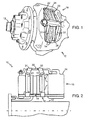
- FIG. 1 depicts an example of an embodiment of a disc brake device according to the invention.
- a disc brake device 10 is fitted to, and adapted to braking, a wheel shaft 12.
- the disc brake device 10 comprises a brake disc 14 mounted on the wheel shaft 12, and a brake yoke 16 fitted non-rotatably and adapted to gripping with controllable force about the brake disc 14.
- the brake yoke 16 in FIG. 2 comprises a lining carrier 18 on which a first and a second brake lining 20, 22 rest.
- a yoke saddle 24 which surrounds the brake linings 20, 22 rests above, and is axially supported for movement in the lining carrier 18.
- a brake piston 26 is adapted, upon brake application, to pressing the first brake lining 20 against the brake disc 14, whereupon corresponding reaction forces push the yoke saddle 24 and hence the second brake lining 22 with substantially the same force in the other direction, i.e. towards the other side of the brake disc 14.
- In the upper portion of the yoke saddle 24 there is an assembly aperture 28 ( FIG. 1 ) which makes it possible to change the brake linings 20, 22 without removing the brake yoke 16.
- a removable lining retainer 30 adapted, with a brake lining spring 32 which is fastened to the lining retainer 30 and takes the form of a leaf spring, to pushing the brake lining 20 radially towards the shaft 12 and axially away from the disc 14.
- a tab ( FIGS. 4A-B ) on the leaf spring 32 is adapted to indicating when the wear on the brake lining 20 reaches a predetermined level.
- a corresponding leaf spring 31 for the lining 22 is also depicted in the diagram.
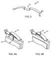
- FIG. 3 depicts an example of how a brake lining spring 31, 32 may be configured.
- a bent portion 35 in the form of an undercut trapezoidal profile allows a releasable connection relative to the lining retainer.
- the spring 32 is bent in such a way that it is adapted to pushing a lining 20 both downwards (arrow 1) and axially (arrow 2).
- the axial force is provided, for example, by the respective arms of the spring being somewhat rotated or by the bent portion 35 giving them a slope relative to the plane of the lining retainer.
- the spring 32 is further provided with a curved tab (not depicted in FIG. 3 ), the configuration and function of which are illustrated in more detail in FIGS. 4A-B .
- FIGS. 4A-B are detail views of an embodiment of a spring 32 which comprises a tab with indicator function.
- FIG. 4A depicts the spring in a tensioned state.
- a sacrificial portion belonging to the spring 32 is connected to the brake lining 20 in such a way that when the connection is worn away against the brake disc 14, the spring 32 will describe a springing movement whereby an indicator element 38 will spring out through the assembly aperture 28 of the brake piston and indicate that the brake lining 20 has reached a predetermined wear level.
- the connection may be by adhesive bonding or soldering, a tab on the brake lining being adapted to hooking firmly in a bend in the sacrificial portion of the spring, or some other suitable connection.
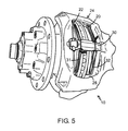
- FIG. 5 depicts another example of an embodiment of a disc brake device according to the invention, in which the springs 31, 32 take the form of wire springs.
- One end of each wire spring 31, 32 runs down through a hole in the respective brake lining 22, 20 and up again to abut and press against the lining retainer 30.
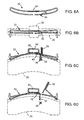
- FIG. 6A is a view from above of an unloaded spring 32 according to the embodiment in FIG. 5 .
- this spring 32 a brake lining 20 and the lining retainer 30 are raised from the yoke 16 to illustrate more clearly the function of the spring 32 in cooperation with the lining retainer 30 and the lining 20.
- the wire spring 32 is curved in a double arc in which the respective end of the arc is adapted to abutting against the brake lining 20 and to springingly pushing it radially in the direction towards the shaft (the arrows in FIG. 6C ) and axially away from the disc (the arrows in 6B).
- the wire spring 32 further has a section 34 adapted to surrounding, and connecting the spring 32 to, the lining retainer 30; a sacrificial section 36 adapted to running down through a hole 33 in the wearing material of the brake lining 20; an indicator section 38 and a section 40 adapted to being tensioned and springingly abutting and pressing up against the lining retainer 30.
- the lining retainer 30 In the assembled state ( FIGS. 6B-C ) the lining retainer 30 will, via the section 40, hold down the indicator section 38 which would otherwise, owing to the tensioning of the spring, endeavour to move away from the shaft 12 ( FIG. 5 ).
- the indicator section 38 springs up and indicates that the brake lining 20 has reached a predetermined worn-down level.
- the indicator element or indicator section may be adapted to springing up through an indicating hole in the cover, but the indication may be read in many ways, e.g. visually, mechanically, optically or electromechanically.
- the indication may also be connected to a warning lamp in the vehicle's instrument panel, to the vehicle's computer or by radio to, for example, a service station.
- a brake lining spring in the form of a leaf spring may be combined with an indicator spring in the form of a leaf, wire or coil spring provided with a sacrificial section and/or an abradable connection to a lining.
- the spring need not necessarily be connected to the lining retainer by surrounding it as illustrated in the diagrams. It may be connected in some other way, e.g. by a fastening device, or be connected to some other part of the yoke. In fact, it is not even necessary that the spring be connected to the yoke; it may instead be fastened to, for example, the brake lining, or be tensioned in the space between the brake lining and some point on the yoke by its own tensioning force. Nor is it necessary that the spring be worn away in order to achieve an indicator function; other embodiments may for example comprise the spring being worn free from a fastening, e.g.
- the fastening need not be arranged through a hole in the wearing material, as it may equally well be arranged in a slit or on an edge of the wearing material at a position situated at a suitable distance from the lining plate on which the wearing material is arranged.
- the lining retainer be configured as illustrated; it may also take other forms, e.g. that of a cover covering the whole of the assembly aperture, and/or be provided with various kinds of means for releasable connection to a brake lining spring/indicator spring/return spring.
Landscapes
- Engineering & Computer Science (AREA)
- General Engineering & Computer Science (AREA)
- Mechanical Engineering (AREA)
- Braking Arrangements (AREA)
Claims (12)
- Scheibenbremsvorrichtung, umfassend:eine Bremsscheibe (14) mit zwei entgegengesetzten Bremsflächen und die dazu ausgebildet ist, mit einer drehbaren Welle (12) verbunden zu werden; undeinen Bremssattel (16), der dazu ausgebildet ist, mit einem nicht drehbaren Teil einer Maschine oder eines Fahrzeugs verbunden zu werden und sich frei von der Bremsscheibe (14) zu bewegen und letztere mit zwei Seitenteilen zu überspannen, die einen Teil des Bremssattels (16) bilden und jedes sich dabei entlang eines Teils der entsprechenden Bremsflächen erstreckt; wobei der Bremssattel (16) weiter mit Bremsbelägen (20, 22) und einem Bremskolben (26) versehen ist, welcher in einem Seitenteil angeordnet und dazu ausgebildet ist, steuerbar den Bremsbelag (20) gegen die Bremsscheibe (14) zu drücken,wobei die Bremsscheibe dadurch gekennzeichnet ist,
dass sie eine Anzeigefeder (32) umfasst, die dazu ausgebildet ist, durch das Anbringen an dem Bremsbelag (20) gespannt zu werden, wobei die Anzeigefeder umfasst:einen Verschleißbereich (36), welcher mit der Anzeigefeder verbunden ist und dazu ausgebildet ist, mit dem Bremsbelag (20) verbunden zu werden, und eine solche Erstreckung aufweist, dass der Verschleißbereich (36) durch Reiben an der Bremsscheibe (14) abgetragen wird, oder alternativ, von einer Befestigung in dem Verschleißmaterial des Bremsbelags (20) freikommt, wenn die Abnutzung an dem Bremsbelag (20) ein vorgegebenes Ausmaß erreicht; undein Anzeigeelement (38), das mit der Anzeigefeder (32) verbunden und dazu ausgebildet ist, unter der Spannkraft der Anzeigefeder (32), eine Sprung- bzw. Federbewegung auszuführen, wenn der aufrauende Bereich (36) abgetragen wurde oder alternativ, von einer Befestigung in dem Verschleißmaterial des Bremsbelags (20) frei gekommen ist, um dabei anzuzeigen, dass die Abnutzung an dem Bremsbelag (20) einen vorgegebenen Grad erreicht hat. - Scheibenbremsvorrichtung nach Anspruch 1, in welcher eine Rückstellfeder (32) dazu ausgebildet ist, die Beläge (20, 22) in axialer Richtung auseinander zu ziehen oder zu drücken.
- Scheibenbremsvorrichtung nach Anspruch 1, in welcher die Rückstellfeder und die Anzeigefeder ein und dieselbe Feder (32) sind.
- Scheibenbremsvorrichtung nach einem der Ansprüche 1 bis 3, in welcher die Feder (32) auch dazu ausgebildet ist, einen Bremsbelag (20, 22) radial in Richtung der Welle (12) zu drücken.
- Scheibenbremsvorrichtung nach einem der Ansprüche 1 bis 4, in welcher die Feder (32) eine Drahtfeder ist.
- Scheibenbremsvorrichtung nach einem der Ansprüche 2 bis 5, in welcher der Bremssattel einen Belagträger (18), der an einem bestimmten Punkt an einem Fahrzeug oder einer Maschine verbunden ist, und einen Sattel (24) umfasst, welcher für eine lineare Bewegung in axialer Richtung gelagert ist und den Belaghalter (30) und den Bremskolben (26) umfasst; und in welchem die Angrenzungsfläche der Feder (32) an dem Bremsbelag (20, 22) eine Reibfläche für die axiale Bewegung des Sattels (24) bezüglich des Bremsbelags (20, 22) bildet.
- Scheibenbremsvorrichtung nach einem der Ansprüche 2 bis 6, in welcher die Feder (32) ausgebildet ist, eine erste und eine zweite Angrenzungsfläche an dem Bremsbelag (20, 22) aufzuweisen, und eine solche Erstreckung aufweist, dass die Angrenzungsflächen dazu ausgebildet sind, im Wesentlichen soweit voneinander gelegen zu sein, wie es der Bereich des Rands des Bremsbelags (20, 22), welcher in Richtung der Baugruppenöffnung (28) gerichtet ist, erlaubt.
- Scheibenbremsvorrichtung nach Anspruch 7, in welcher die Federkraft, mit welcher die erste Angrenzungsfläche der Feder (32) auf den Bremsbelag (20, 22) drückt, im Wesentlichen unabhängig von der Federkraft ist, mit welcher die zweite Angrenzungsfiläche der Feder (32) auf den Bremsbelag (20, 22) drückt.
- Feder in der Gestalt einer Drahtfeder (32), die dazu ausgebildet ist, in einen Bremssattel (16) eingesetzt zu werden, wobei die Feder (32) umfasst:einen Belaghalterabschnitt, der gekrümmt ist, um einen Bogen zu formen, in welchem das entsprechende Ende des Bogens dazu ausgebildet ist, an dem Bremsbelag (20) anzugrenzen;einen Verbindungsabschnitt (34), der dazu ausgebildet ist, die Feder (32) mit einem Belaghalter (30) oder einer Baugruppenöffnungsabdeckung zu verbinden;einen Spannabschnitt (40), der dazu ausgebildet ist, gespannt und federnd anzuliegen und gegen den Belaghalter (30) oder die Baugruppenöffnungsabdeckung zu drücken;wobei die Feder dadurch gekennzeichnet ist, dass der Belaghalterabschnitt dazu ausgebildet ist, den Bremsbelag (20) federnd radial in Richtung einer Welle (12) hin und axial von einer Bremsscheibe (14) wegzudrücken;ein aufrauender Verschleißbereich (36), der dazu ausgebildet ist, mit dem Verschleißmaterial des Bremsbelags (20) derart verbunden zu werden, dass der Verschleißbereich abgetragen wird, wenn der Bremsbelag einen vorgegebenen Abnutzungsgrad erreicht hat, wobei der Spannabschnitt (40) sich von dem Rest der Feder (32) separiert; und dassein Anzeigeabschnitt (38) dazu ausgebildet ist, aus einer Baugruppenöffnung (28) in dem Bremssattel (16) und/oder durch eine Öffnung in einer Abdeckung über der Baugruppenöffnung (28) herauszuspringen, wenn sich der Spannabschnitt (40) von dem Rest der Feder (32) abspaltet.
- Fahrzeug, das mit einer Scheibenbremsvorrichtung (10) nach einem der Ansprüche 1 bis 8 oder einer Feder (32) nach Anspruch 9 ausgestaltet ist.
- Verwendung einer Scheibenbremsvorrichtung (10) nach einem der Ansprüche 1 bis 8 zum Bremsen einer Drehbewegung.
- Verwendung einer Feder (32) nach Anspruch 9 zum Anzeigen, dass die Abnutzung an dem Bremsbelag einen vorgegebenen Grad erreicht hat.
Applications Claiming Priority (1)
| Application Number | Priority Date | Filing Date | Title |
|---|---|---|---|
| SE0702220A SE531160C2 (sv) | 2007-10-04 | 2007-10-04 | Skivbromsanordning, fjäder och fordon samt användning av sådan skivbromsanordning eller fjäder |
Publications (2)
| Publication Number | Publication Date |
|---|---|
| EP2045482A1 EP2045482A1 (de) | 2009-04-08 |
| EP2045482B1 true EP2045482B1 (de) | 2010-11-24 |
Family
ID=39941902
Family Applications (1)
| Application Number | Title | Priority Date | Filing Date |
|---|---|---|---|
| EP08165826A Not-in-force EP2045482B1 (de) | 2007-10-04 | 2008-10-03 | Scheibenbremsvorrichtung, Feder und Fahrzeug mit einer solchen Scheibenbremsvorrichtung oder Feder |
Country Status (4)
| Country | Link |
|---|---|
| EP (1) | EP2045482B1 (de) |
| AT (1) | ATE489563T1 (de) |
| DE (1) | DE602008003636D1 (de) |
| SE (1) | SE531160C2 (de) |
Cited By (1)
| Publication number | Priority date | Publication date | Assignee | Title |
|---|---|---|---|---|
| WO2013180555A1 (ko) * | 2012-05-31 | 2013-12-05 | 상신브레이크 주식회사 | 마모 보정구조를 갖는 차량용 디스크 브레이크 |
Families Citing this family (2)
| Publication number | Priority date | Publication date | Assignee | Title |
|---|---|---|---|---|
| JP6134926B2 (ja) * | 2013-06-28 | 2017-05-31 | 日立オートモティブシステムズ株式会社 | ディスクブレーキ |
| DE102018207180A1 (de) * | 2018-05-08 | 2019-11-14 | Shimano Components (Malaysia) Sdn. Bhd. | Scheibenbremssattel mit einem Verschleißanzeiger und Vorspannbauteil für Scheibenbremssattel mit einem Verschleißanzeiger |
Family Cites Families (7)
| Publication number | Priority date | Publication date | Assignee | Title |
|---|---|---|---|---|
| JPS562438U (de) * | 1979-06-20 | 1981-01-10 | ||
| DE3726232A1 (de) * | 1986-08-19 | 1988-03-03 | Volkswagen Ag | Vorrichtung zur ermittlung des verschleisses eines reibbelags, insbesondere eines bremsbelags |
| EP0326774B2 (de) | 1988-02-05 | 1995-09-13 | Alliedsignal Europe Services Techniques | Scheibenbremse und Bremsbacke dafür |
| FR2681922B1 (fr) * | 1991-09-30 | 1993-11-26 | Bendix Europe Services Technique | Organe de friction muni d'un dispositif indicateur d'usure et frein a disque equipe d'un tel organe. |
| JP3213191B2 (ja) | 1995-01-27 | 2001-10-02 | トキコ株式会社 | ディスクブレーキ |
| GB9507723D0 (en) * | 1995-04-13 | 1995-05-31 | Madison Cycles Plc | Improvements to brake blocks |
| JP4668844B2 (ja) * | 2006-05-29 | 2011-04-13 | 曙ブレーキ工業株式会社 | 対向ピストン型ディスクブレーキ |
-
2007
- 2007-10-04 SE SE0702220A patent/SE531160C2/sv unknown
-
2008
- 2008-10-03 DE DE602008003636T patent/DE602008003636D1/de active Active
- 2008-10-03 EP EP08165826A patent/EP2045482B1/de not_active Not-in-force
- 2008-10-03 AT AT08165826T patent/ATE489563T1/de not_active IP Right Cessation
Cited By (1)
| Publication number | Priority date | Publication date | Assignee | Title |
|---|---|---|---|---|
| WO2013180555A1 (ko) * | 2012-05-31 | 2013-12-05 | 상신브레이크 주식회사 | 마모 보정구조를 갖는 차량용 디스크 브레이크 |
Also Published As
| Publication number | Publication date |
|---|---|
| SE0702220L (sv) | 2009-01-07 |
| DE602008003636D1 (de) | 2011-01-05 |
| SE531160C2 (sv) | 2009-01-07 |
| ATE489563T1 (de) | 2010-12-15 |
| EP2045482A1 (de) | 2009-04-08 |
Similar Documents
| Publication | Publication Date | Title |
|---|---|---|
| RU2490525C2 (ru) | Тормозная накладка дискового тормоза | |
| CN104271978B (zh) | 带有复位装置的盘式制动器和制动衬片 | |
| US9726243B2 (en) | Disc brake pad retention system and mounting method | |
| JP5368528B2 (ja) | 静止用機械式ディスクブレーキ | |
| US4467897A (en) | Disc brake with first and second springs for preventing the vibration of friction pad | |
| CN101825148A (zh) | 盘式制动器 | |
| EP2584212B1 (de) | Mechanisch arretierende Scheibenbremse | |
| JPS6014216B2 (ja) | フロ−ティングキャリパ・スポット型ディスクブレ−キ | |
| EP2045482B1 (de) | Scheibenbremsvorrichtung, Feder und Fahrzeug mit einer solchen Scheibenbremsvorrichtung oder Feder | |
| EP0944779B1 (de) | Scheibenbremse | |
| KR101238254B1 (ko) | 마찰 요소 및 디스크 브레이크 | |
| US10697513B2 (en) | Brake pad wear detector | |
| JPS63115924A (ja) | ディスクブレーキ用パッド及び同パッドを具備したディスクブレーキ | |
| JP6140659B2 (ja) | 摩擦パッドおよびブレーキキャリパーシステム | |
| US4085827A (en) | Disc brake wear indicator | |
| US20250146547A1 (en) | Disc Brake for a Utility Vehicle, and Brake Lining for a Disc Brake | |
| EP1045164A1 (de) | Preiswerter Bremssensor | |
| GB2353830A (en) | Friction clutch wear indication | |
| JP2006138475A (ja) | ディスクブレーキ | |
| US20070068747A1 (en) | Self-energizing sliding caliper | |
| US4311214A (en) | Disc brake | |
| KR20020007609A (ko) | 디스크 브레이크의 패드마모감지장치 | |
| GB2107013A (en) | A brake pad assembly including a feeler of a wear indicator means | |
| JP6025668B2 (ja) | 摩擦パッドおよびブレーキキャリパーシステム | |
| JP4926121B2 (ja) | ディスクブレーキ |
Legal Events
| Date | Code | Title | Description |
|---|---|---|---|
| PUAI | Public reference made under article 153(3) epc to a published international application that has entered the european phase |
Free format text: ORIGINAL CODE: 0009012 |
|
| AK | Designated contracting states |
Kind code of ref document: A1 Designated state(s): AT BE BG CH CY CZ DE DK EE ES FI FR GB GR HR HU IE IS IT LI LT LU LV MC MT NL NO PL PT RO SE SI SK TR |
|
| AX | Request for extension of the european patent |
Extension state: AL BA MK RS |
|
| 17P | Request for examination filed |
Effective date: 20091003 |
|
| AKX | Designation fees paid |
Designated state(s): AT BE BG CH CY CZ DE DK EE ES FI FR GB GR HR HU IE IS IT LI LT LU LV MC MT NL NO PL PT RO SE SI SK TR |
|
| 17Q | First examination report despatched |
Effective date: 20091207 |
|
| GRAP | Despatch of communication of intention to grant a patent |
Free format text: ORIGINAL CODE: EPIDOSNIGR1 |
|
| GRAS | Grant fee paid |
Free format text: ORIGINAL CODE: EPIDOSNIGR3 |
|
| GRAA | (expected) grant |
Free format text: ORIGINAL CODE: 0009210 |
|
| AK | Designated contracting states |
Kind code of ref document: B1 Designated state(s): AT BE BG CH CY CZ DE DK EE ES FI FR GB GR HR HU IE IS IT LI LT LU LV MC MT NL NO PL PT RO SE SI SK TR |
|
| REG | Reference to a national code |
Ref country code: GB Ref legal event code: FG4D |
|
| REG | Reference to a national code |
Ref country code: CH Ref legal event code: EP |
|
| REG | Reference to a national code |
Ref country code: IE Ref legal event code: FG4D |
|
| REF | Corresponds to: |
Ref document number: 602008003636 Country of ref document: DE Date of ref document: 20110105 Kind code of ref document: P |
|
| REG | Reference to a national code |
Ref country code: NL Ref legal event code: VDEP Effective date: 20101124 |
|
| LTIE | Lt: invalidation of european patent or patent extension |
Effective date: 20101124 |
|
| PG25 | Lapsed in a contracting state [announced via postgrant information from national office to epo] |
Ref country code: NO Free format text: LAPSE BECAUSE OF FAILURE TO SUBMIT A TRANSLATION OF THE DESCRIPTION OR TO PAY THE FEE WITHIN THE PRESCRIBED TIME-LIMIT Effective date: 20110224 Ref country code: LT Free format text: LAPSE BECAUSE OF FAILURE TO SUBMIT A TRANSLATION OF THE DESCRIPTION OR TO PAY THE FEE WITHIN THE PRESCRIBED TIME-LIMIT Effective date: 20101124 |
|
| PG25 | Lapsed in a contracting state [announced via postgrant information from national office to epo] |
Ref country code: CY Free format text: LAPSE BECAUSE OF FAILURE TO SUBMIT A TRANSLATION OF THE DESCRIPTION OR TO PAY THE FEE WITHIN THE PRESCRIBED TIME-LIMIT Effective date: 20101124 Ref country code: IS Free format text: LAPSE BECAUSE OF FAILURE TO SUBMIT A TRANSLATION OF THE DESCRIPTION OR TO PAY THE FEE WITHIN THE PRESCRIBED TIME-LIMIT Effective date: 20110324 Ref country code: HR Free format text: LAPSE BECAUSE OF FAILURE TO SUBMIT A TRANSLATION OF THE DESCRIPTION OR TO PAY THE FEE WITHIN THE PRESCRIBED TIME-LIMIT Effective date: 20101124 Ref country code: NL Free format text: LAPSE BECAUSE OF FAILURE TO SUBMIT A TRANSLATION OF THE DESCRIPTION OR TO PAY THE FEE WITHIN THE PRESCRIBED TIME-LIMIT Effective date: 20101124 Ref country code: SI Free format text: LAPSE BECAUSE OF FAILURE TO SUBMIT A TRANSLATION OF THE DESCRIPTION OR TO PAY THE FEE WITHIN THE PRESCRIBED TIME-LIMIT Effective date: 20101124 Ref country code: SE Free format text: LAPSE BECAUSE OF FAILURE TO SUBMIT A TRANSLATION OF THE DESCRIPTION OR TO PAY THE FEE WITHIN THE PRESCRIBED TIME-LIMIT Effective date: 20101124 Ref country code: BG Free format text: LAPSE BECAUSE OF FAILURE TO SUBMIT A TRANSLATION OF THE DESCRIPTION OR TO PAY THE FEE WITHIN THE PRESCRIBED TIME-LIMIT Effective date: 20110224 Ref country code: PT Free format text: LAPSE BECAUSE OF FAILURE TO SUBMIT A TRANSLATION OF THE DESCRIPTION OR TO PAY THE FEE WITHIN THE PRESCRIBED TIME-LIMIT Effective date: 20110324 Ref country code: FI Free format text: LAPSE BECAUSE OF FAILURE TO SUBMIT A TRANSLATION OF THE DESCRIPTION OR TO PAY THE FEE WITHIN THE PRESCRIBED TIME-LIMIT Effective date: 20101124 Ref country code: AT Free format text: LAPSE BECAUSE OF FAILURE TO SUBMIT A TRANSLATION OF THE DESCRIPTION OR TO PAY THE FEE WITHIN THE PRESCRIBED TIME-LIMIT Effective date: 20101124 Ref country code: LV Free format text: LAPSE BECAUSE OF FAILURE TO SUBMIT A TRANSLATION OF THE DESCRIPTION OR TO PAY THE FEE WITHIN THE PRESCRIBED TIME-LIMIT Effective date: 20101124 |
|
| PG25 | Lapsed in a contracting state [announced via postgrant information from national office to epo] |
Ref country code: GR Free format text: LAPSE BECAUSE OF FAILURE TO SUBMIT A TRANSLATION OF THE DESCRIPTION OR TO PAY THE FEE WITHIN THE PRESCRIBED TIME-LIMIT Effective date: 20110225 |
|
| PG25 | Lapsed in a contracting state [announced via postgrant information from national office to epo] |
Ref country code: CZ Free format text: LAPSE BECAUSE OF FAILURE TO SUBMIT A TRANSLATION OF THE DESCRIPTION OR TO PAY THE FEE WITHIN THE PRESCRIBED TIME-LIMIT Effective date: 20101124 Ref country code: ES Free format text: LAPSE BECAUSE OF FAILURE TO SUBMIT A TRANSLATION OF THE DESCRIPTION OR TO PAY THE FEE WITHIN THE PRESCRIBED TIME-LIMIT Effective date: 20110307 Ref country code: EE Free format text: LAPSE BECAUSE OF FAILURE TO SUBMIT A TRANSLATION OF THE DESCRIPTION OR TO PAY THE FEE WITHIN THE PRESCRIBED TIME-LIMIT Effective date: 20101124 Ref country code: BE Free format text: LAPSE BECAUSE OF FAILURE TO SUBMIT A TRANSLATION OF THE DESCRIPTION OR TO PAY THE FEE WITHIN THE PRESCRIBED TIME-LIMIT Effective date: 20101124 |
|
| PG25 | Lapsed in a contracting state [announced via postgrant information from national office to epo] |
Ref country code: PL Free format text: LAPSE BECAUSE OF FAILURE TO SUBMIT A TRANSLATION OF THE DESCRIPTION OR TO PAY THE FEE WITHIN THE PRESCRIBED TIME-LIMIT Effective date: 20101124 Ref country code: RO Free format text: LAPSE BECAUSE OF FAILURE TO SUBMIT A TRANSLATION OF THE DESCRIPTION OR TO PAY THE FEE WITHIN THE PRESCRIBED TIME-LIMIT Effective date: 20101124 Ref country code: SK Free format text: LAPSE BECAUSE OF FAILURE TO SUBMIT A TRANSLATION OF THE DESCRIPTION OR TO PAY THE FEE WITHIN THE PRESCRIBED TIME-LIMIT Effective date: 20101124 Ref country code: DK Free format text: LAPSE BECAUSE OF FAILURE TO SUBMIT A TRANSLATION OF THE DESCRIPTION OR TO PAY THE FEE WITHIN THE PRESCRIBED TIME-LIMIT Effective date: 20101124 |
|
| PLBE | No opposition filed within time limit |
Free format text: ORIGINAL CODE: 0009261 |
|
| STAA | Information on the status of an ep patent application or granted ep patent |
Free format text: STATUS: NO OPPOSITION FILED WITHIN TIME LIMIT |
|
| 26N | No opposition filed |
Effective date: 20110825 |
|
| REG | Reference to a national code |
Ref country code: DE Ref legal event code: R097 Ref document number: 602008003636 Country of ref document: DE Effective date: 20110825 |
|
| PG25 | Lapsed in a contracting state [announced via postgrant information from national office to epo] |
Ref country code: IT Free format text: LAPSE BECAUSE OF FAILURE TO SUBMIT A TRANSLATION OF THE DESCRIPTION OR TO PAY THE FEE WITHIN THE PRESCRIBED TIME-LIMIT Effective date: 20101124 |
|
| PG25 | Lapsed in a contracting state [announced via postgrant information from national office to epo] |
Ref country code: MC Free format text: LAPSE BECAUSE OF NON-PAYMENT OF DUE FEES Effective date: 20111031 |
|
| REG | Reference to a national code |
Ref country code: FR Ref legal event code: ST Effective date: 20120629 |
|
| REG | Reference to a national code |
Ref country code: IE Ref legal event code: MM4A |
|
| PG25 | Lapsed in a contracting state [announced via postgrant information from national office to epo] |
Ref country code: FR Free format text: LAPSE BECAUSE OF NON-PAYMENT OF DUE FEES Effective date: 20111102 |
|
| PG25 | Lapsed in a contracting state [announced via postgrant information from national office to epo] |
Ref country code: IE Free format text: LAPSE BECAUSE OF NON-PAYMENT OF DUE FEES Effective date: 20111003 |
|
| PG25 | Lapsed in a contracting state [announced via postgrant information from national office to epo] |
Ref country code: MT Free format text: LAPSE BECAUSE OF FAILURE TO SUBMIT A TRANSLATION OF THE DESCRIPTION OR TO PAY THE FEE WITHIN THE PRESCRIBED TIME-LIMIT Effective date: 20101124 |
|
| PG25 | Lapsed in a contracting state [announced via postgrant information from national office to epo] |
Ref country code: LU Free format text: LAPSE BECAUSE OF NON-PAYMENT OF DUE FEES Effective date: 20111003 |
|
| REG | Reference to a national code |
Ref country code: CH Ref legal event code: PL |
|
| GBPC | Gb: european patent ceased through non-payment of renewal fee |
Effective date: 20121003 |
|
| PG25 | Lapsed in a contracting state [announced via postgrant information from national office to epo] |
Ref country code: GB Free format text: LAPSE BECAUSE OF NON-PAYMENT OF DUE FEES Effective date: 20121003 Ref country code: CH Free format text: LAPSE BECAUSE OF NON-PAYMENT OF DUE FEES Effective date: 20121031 Ref country code: LI Free format text: LAPSE BECAUSE OF NON-PAYMENT OF DUE FEES Effective date: 20121031 |
|
| PG25 | Lapsed in a contracting state [announced via postgrant information from national office to epo] |
Ref country code: TR Free format text: LAPSE BECAUSE OF FAILURE TO SUBMIT A TRANSLATION OF THE DESCRIPTION OR TO PAY THE FEE WITHIN THE PRESCRIBED TIME-LIMIT Effective date: 20101124 |
|
| PG25 | Lapsed in a contracting state [announced via postgrant information from national office to epo] |
Ref country code: HU Free format text: LAPSE BECAUSE OF FAILURE TO SUBMIT A TRANSLATION OF THE DESCRIPTION OR TO PAY THE FEE WITHIN THE PRESCRIBED TIME-LIMIT Effective date: 20101124 |
|
| PGFP | Annual fee paid to national office [announced via postgrant information from national office to epo] |
Ref country code: DE Payment date: 20150929 Year of fee payment: 8 |
|
| REG | Reference to a national code |
Ref country code: DE Ref legal event code: R119 Ref document number: 602008003636 Country of ref document: DE |
|
| PG25 | Lapsed in a contracting state [announced via postgrant information from national office to epo] |
Ref country code: DE Free format text: LAPSE BECAUSE OF NON-PAYMENT OF DUE FEES Effective date: 20170503 |