EP2045431A2 - Covering with integrated heat insulation - Google Patents
Covering with integrated heat insulation Download PDFInfo
- Publication number
- EP2045431A2 EP2045431A2 EP08016511A EP08016511A EP2045431A2 EP 2045431 A2 EP2045431 A2 EP 2045431A2 EP 08016511 A EP08016511 A EP 08016511A EP 08016511 A EP08016511 A EP 08016511A EP 2045431 A2 EP2045431 A2 EP 2045431A2
- Authority
- EP
- European Patent Office
- Prior art keywords
- outer lining
- frame
- profile
- chamber
- lining according
- Prior art date
- Legal status (The legal status is an assumption and is not a legal conclusion. Google has not performed a legal analysis and makes no representation as to the accuracy of the status listed.)
- Granted
Links
Images


Classifications
-
- E—FIXED CONSTRUCTIONS
- E06—DOORS, WINDOWS, SHUTTERS, OR ROLLER BLINDS IN GENERAL; LADDERS
- E06B—FIXED OR MOVABLE CLOSURES FOR OPENINGS IN BUILDINGS, VEHICLES, FENCES OR LIKE ENCLOSURES IN GENERAL, e.g. DOORS, WINDOWS, BLINDS, GATES
- E06B3/00—Window sashes, door leaves, or like elements for closing wall or like openings; Layout of fixed or moving closures, e.g. windows in wall or like openings; Features of rigidly-mounted outer frames relating to the mounting of wing frames
- E06B3/30—Coverings, e.g. protecting against weather, for decorative purposes
- E06B3/301—Coverings, e.g. protecting against weather, for decorative purposes consisting of prefabricated profiled members or glass
- E06B3/302—Covering wooden frames with metal or plastic profiled members
-
- E—FIXED CONSTRUCTIONS
- E06—DOORS, WINDOWS, SHUTTERS, OR ROLLER BLINDS IN GENERAL; LADDERS
- E06B—FIXED OR MOVABLE CLOSURES FOR OPENINGS IN BUILDINGS, VEHICLES, FENCES OR LIKE ENCLOSURES IN GENERAL, e.g. DOORS, WINDOWS, BLINDS, GATES
- E06B3/00—Window sashes, door leaves, or like elements for closing wall or like openings; Layout of fixed or moving closures, e.g. windows in wall or like openings; Features of rigidly-mounted outer frames relating to the mounting of wing frames
- E06B3/04—Wing frames not characterised by the manner of movement
- E06B3/263—Frames with special provision for insulation
- E06B3/26345—Frames with special provision for insulation for wooden or plastic section members
Definitions
- the present invention relates on the one hand to an outer covering with integrated thermal insulation for in particular weather-resistant clad frames of windows, doors or similar facade elements. Furthermore, the present invention relates to a method for producing a weatherproof exterior clad frame of a door, a window or similar facade elements.
- a generic outer lining is from the EP 1 178 177 B1 known.
- the outer cladding comprises an aluminum shell as outer cladding element, which by design must be foamed with an insulating material in the form of a PU foam.
- the outer cladding consisting of aluminum shell and PU foam is then either glued directly to the frame or mounted on frame-side holders by means of inside, C-shaped mounting rails.
- the aforementioned construction is complex in its production and therefore expensive.
- the outer lining in the corner area can not be welded due to the presence of insulating foam.
- the object of the present invention is to provide a novel outer cladding, which allows a simplification of the production of the outer cladding, without a significant deterioration of the insulating effect occurs.
- a chamber system consisting of at least two, preferably a plurality of chambers is provided as insulation and between the outer lining and the frame of the window or the door, the individual chambers substantially perpendicular to the plane of the outer lining considered stratified are oriented to each other.
- the individual chambers which exist in layers from the inside to the outside, have the effect that the passage of cold from the outside via the outer lining element to the frame is prevented or at least greatly restricted.
- the individual chambers therefore act as a cold barrier.
- the invention makes it possible first to produce a complete frame of outer lining elements, for example by welding in the corner area or by connecting the outer lining elements by means of corner angle with punching and only then the support profile on the Set up complete frame. As a result, in contrast to previously a prefabrication of composite frame possible and consequently the production of the outer lining considerably simpler and cheaper.
- the drainage is realized in the present invention in the form of a drainage channel formed only by drilling in the walls of the chambers of the support profile.
- the outer cladding element is slightly spaced from the support profile at least in the frontal region. This results in a gap between the support profile and the outer cladding element, so that the opening of the drainage channel is optically covered by the outer cladding element on the support profile.
- the support profile can fill a large part of the dewatering chamber and thus reduces the volume of the same, which is advantageous with regard to the insulation properties. If the support profile also has holes in the area of the drainage chamber, seepage water from the outside glazing gasket can pass through the aforementioned Supporting profile ie its chamber are passed through down. In turn, reducing the volume of the dewatering chamber results in an improved isothermal course.
- the drainage guided according to the invention by the chamber of the support profile also relieves the visor seal.
- an additional profiled part glued to the glazing element is provided, against which the trim frame gasket rests. This profile part holds the glazing element from the outside and sits below the glazing gasket. The profile part also causes leachate from the glazing gasket into the drainage channel of the support profile is passed.
- a particularly good thermal insulation can be achieved if at least one, preferably a plurality of the layers arranged in layers extending over the entire width of the support profile.
- the support profile is preferably provided as a strand molded part and is preferably made of plastic, in particular ABS.
- the outer cladding elements are connected as such to a complete frame before connection to the support profile, the outer cladding in the corner region of the outer cladding elements advantageously also have a welded connection.
- a clip connection is expediently provided, for example, by two provided on the outer cladding element, (viewed in cross-section) opposite connection points.
- the support profile in the region of the end face of the frame does not extend to the outside but ends at an attached to the outside of the frame body, such as an insulating block or annendoppelungsang.
- an insulating block ie a material block consisting of heat-insulating material, an optimal isothermal course and thus a particularly good insulation is achieved.
- the support profile is expediently mounted by means of a holder, in particular rotary holder, on the respective frame.
- a direct screw connection can also be provided.
- the chambers can be filled if necessary with a Dämmmaschine, whereby a layer-like arrangement of individual Dämm stressesn arises.
- Dämm emotions may be solid insulation blocks, which are inserted into the support profile contour-matched.
- a part of the support profile may remain free of insulating materials, for example in the region of the drainage channel.
- This can be realized in the support profile by inwardly directed projections or lugs, which prevent a insulating body from slipping into the region of the drainage channel.
- connection in the corner is advantageously carried out by welding or soldering.
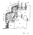
- Fig. 1 shows a cross section through the frame 1 and sash 2 of a turn / tilt window. In the area of the casement 2 there is a glazing element 3.
- each support section 50, 51 On the outside.
- an independent, preferably made of metal or plastic outer cladding element 52, 53 for example in the form of an aluminum profile, on each support section 50, 51 on the outside.
- a mounting connection 12 and 13 is provided in the form of hooks each, which together cause a locking of the aforementioned parts together.
- the respective support profile 50, 51 and outer cladding element 52, 51 in this case form an air space or gap 21 to each other both on the outside end face and in the rollover area.
- the respective support profile 50, 51 is on the front side of the window frame 1, for example by means of conventional holder 6, e.g. so-called.
- Rotary holder which engage in a chamber of the support profile 50, 51, connected.
- the respective support profile 50, 51 and the outer cladding element 52, 53 together form a receiving groove 24 for the glazing gasket 22.
- the respective support profile 50, 51 comprises, viewed from outside to inside, a layer sequence of a plurality of chambers 7, 8, 9 and 10, which nevertheless ensure good thermal insulation, ie a good isothermal course, even without insulation filling.
- the two chambers 7 and 8 each extend over the entire side of the support profile. 5
- Reference numeral 15 denotes the frame frame seal, which rests against the support profile 50 and is anchored both in a receiving groove in the frame 1 and in a frame formed by the frame 1 and the support section 51 together receiving groove 25.
- the drainage chamber 18 is located in the region of the face frame seal 15.
- the drainage channel 16 begins in the region of a bore 17 of the support profile 51 on the underside of the dewatering chamber 18. It runs in the region of the dewatering chamber 18 initially substantially parallel to the glazing element 3 and opens concealed by the outer lining element 52 and thus not visible from the outside.
- the support section 51 terminates in the region of the front-side outer side of the window frame 1 on a block of material which may be provided, for example, in the form of an insulating block 11.
- This insulating block 11 is also provided with an outside panel.
- the respective outer lining element 52, 53 has a recess 31 in the rollover area, which allows the insertion of stiffening angle 14. Furthermore, between the outer side of the respective outer lining element 52, 53 and the outer side of the support profile 50, 51 through the air gap 21 sufficient space to provide receptacles for corner angles 26, 27 to ensure a corner joint.
- the support profile 5 has a very good mechanical stability. It is expediently designed as a strand molding and consists of plastic, preferably of ABS.
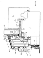
- the embodiment according to Fig. 2 describes a section through a two-part window, the casement 2 abut a fighter 54.
- Per wing frame 2 each have an independent support section 50 is provided with associated outer lining element 52.
- a pair of support profiles 51 located in the region of the front side of the fighter 54, a pair of support profiles 51, which are separated by an insulating block 55 from each other.
- the top-side support section 51 includes the drainage channel 16.
- the support section 51 corresponds to the support section 51 of the construction according to Fig. 2 ,
- Fig. 3 shows a section through a fixed glazing using an outer lining according to the present invention.
- an insulating layer 28 is provided between the support section 51 and the glazing element 3, in turn.
- the support profile 51 is connected via a holder 6 with a fixed glazing frame 53 in connection.
- At the bottom of the support section 51 is an insulating block eleventh
- the construction of the support profile 51 corresponds to the construction of the support profiles 51 of the embodiments of Fig. 1 and 2 ,
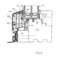
- Fig. 4 shows an embodiment in which only a single, bezel side mounted outer lining element 52 is provided, which covers the gap between the frame 1 and sash 2.
- only a single support profile 50 is provided for this purpose, which has chambers 7, 8, 9 and 10.
- the chamber 10 protrudes into the dewatering chamber 18 and reduces their volume. Further, the drainage channel 16 passes through the chamber 10 therethrough.
- the glazing element 3 is held by a profile part 19, which is connected to the glazing element 3 via an adhesive layer 24.
- a glass retaining profile 30 is provided which engages with its legs in a groove 20 on the sash 2.
- each support profile 50, 51 is assigned its own outer cladding element 52, 53.
- FIG. 5 An alternative embodiment of the present invention shows the Fig. 5 ,
- insulating body 70 are introduced into the chambers 7 and 8 or in the chambers 7, 8 and 9. Due to individual lugs 71 in the support section 51, the drainage channel 16 remains free.
- the insulating body 71 are here also layered.
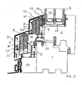
- Fig. 6 shows a frame 80 and a sash 90, both made of plastic.
- the fixing of the support profiles 50, 51 takes place here by means of holder 91, which previously mounted on the frame profile or sash profile, be glued in particular.
- the support profiles 50, 51 are then clipped into the grooves on the holder 91.
- projections engage in an opening on the support section 50 and 51 in the region of the chamber 10 and thereby ensure the holding effect.
- the composite frame will be made of exterior trim elements and support profiles, e.g. mounted on the located on the outside of the frame 1 holder 6.
- the present invention provides a considerable simplification of the production costs in comparison to the previously known solutions and for this reason represents a very special enrichment of the relevant state of the art.
Landscapes
- Engineering & Computer Science (AREA)
- Civil Engineering (AREA)
- Structural Engineering (AREA)
- Wing Frames And Configurations (AREA)
- Securing Of Glass Panes Or The Like (AREA)
- Special Wing (AREA)
Abstract
Description
Die vorliegende Erfindung betrifft zum einen eine Außenverkleidung mit integrierter Wärmedämmung für insbesondere witterungsbeständig verkleidete Rahmen von Fenster, Türen oder ähnlichen Fassadenelementen. Des Weiteren betrifft die vorliegende Erfindung ein Verfahren zur Herstellung eines zum Witterungsschutz im Außenbereich verkleideten Rahmens einer Tür, eines Fensters oder ähnlichen Fassadenelementen.The present invention relates on the one hand to an outer covering with integrated thermal insulation for in particular weather-resistant clad frames of windows, doors or similar facade elements. Furthermore, the present invention relates to a method for producing a weatherproof exterior clad frame of a door, a window or similar facade elements.
Eine gattungsgemäße Außenverkleidung ist aus der
Eine entsprechende Konstruktion ist auch aus der
Aus der
Die Aufgabe der vorliegenden Erfindung besteht darin, eine neuartige Außenverkleidung zur Verfügung zu stellen, die eine Vereinfachung der Herstellung der Außenverkleidung ermöglicht, ohne dass eine nennenswerte Verschlechterung der Dämmwirkung eintritt.The object of the present invention is to provide a novel outer cladding, which allows a simplification of the production of the outer cladding, without a significant deterioration of the insulating effect occurs.
Diese Aufgabe wird bei der gattungsgemäßen Außenverkleidung dadurch gelöst, dass als Isolierung ein Kammersystem, bestehend aus mindestens zwei, vorzugsweise einer Mehrzahl von Kammern vorgesehen ist und zwischen der Außenverkleidung und dem Rahmen des Fensters oder der Tür die einzelnen Kammern im Wesentlichen senkrecht zur Ebene der Außenverkleidung betrachtet schichtartig aneinander liegend orientiert sind.This object is achieved in the generic outer lining characterized in that a chamber system consisting of at least two, preferably a plurality of chambers is provided as insulation and between the outer lining and the frame of the window or the door, the individual chambers substantially perpendicular to the plane of the outer lining considered stratified are oriented to each other.
Die einzelnen von innen nach außen schichtartig vorliegenden Kammern bewirken, dass ein Kälteübertritt von außen über das Außenverkleidungselement hin zum Rahmen unterbunden oder zumindest stark eingeschränkt wird. Die einzelnen Kammern wirken demzufolge als Kältebarriere. Ferner macht es die Erfindung möglich, zunächst einen Komplettrahmen aus Außenverkleidungselementen, beispielsweise durch Schweißen im Eckbereich oder durch Verbindung der Außenverkleidungselemente mittels Eckwinkel mit Verstanzung herzustellen und erst anschließend das Tragprofil auf den Komplettrahmen aufzusetzen. Hierdurch wird im Gegensatz zu bisher eine Vorfertigung von Verbundrahmen möglich und demzufolge die Herstellung der Außenverkleidung erheblich vereinfacht und verbilligt.The individual chambers, which exist in layers from the inside to the outside, have the effect that the passage of cold from the outside via the outer lining element to the frame is prevented or at least greatly restricted. The individual chambers therefore act as a cold barrier. Furthermore, the invention makes it possible first to produce a complete frame of outer lining elements, for example by welding in the corner area or by connecting the outer lining elements by means of corner angle with punching and only then the support profile on the Set up complete frame. As a result, in contrast to previously a prefabrication of composite frame possible and consequently the production of the outer lining considerably simpler and cheaper.
Aufgrund der erfindungsgemäßen Konstruktion muss kein zusätzliches Dämmmaterial innerhalb der betreffenden Kammer bzw. Kammern vorgesehen sein. Die Dämmwirkung ist bereits als solches in die Konstruktion des Tragprofils durch die besondere Anordnung der Kammern integriert. Da kein Dämmmaterial vorgesehen sein muss, kann zudem auf den Einsatz von (bei PU-Schaum notwendigen) Entwässerungsröhrchen verzichtet werden, was zu einer Reduzierung der Bearbeitungstiefe und damit zu einer Einsparung von Herstellkosten führt.Due to the construction according to the invention no additional insulation material must be provided within the chamber or chambers concerned. The insulating effect is already integrated as such in the construction of the support profile by the special arrangement of the chambers. Since no insulating material must be provided, it is also possible to dispense with the use of drainage tubes (which are necessary in the case of PU foam), which leads to a reduction in the machining depth and thus to a reduction in production costs.
Zweckmäßigerweise wird die Entwässerung bei der vorliegenden Erfindung in Form eines lediglich durch Bohrungen in den Wandungen der Kammern des Tragprofils gebildeten Entwässerungskanals realisiert.Appropriately, the drainage is realized in the present invention in the form of a drainage channel formed only by drilling in the walls of the chambers of the support profile.
In vorteilhafter Weise ist das Außenverkleidungselement zum Tragprofil zumindest im stirnseitigen Bereich etwas beabstandet. Hierdurch ergibt sich ein Spalt zwischen dem Tragprofil und dem Außenverkleidungselement, so dass die Öffnung des Entwässerungskanals am Tragprofil durch das Außenverkleidungselement optisch abgedeckt ist.Advantageously, the outer cladding element is slightly spaced from the support profile at least in the frontal region. This results in a gap between the support profile and the outer cladding element, so that the opening of the drainage channel is optically covered by the outer cladding element on the support profile.
Dadurch, dass im Bereich der Blendrahmendichtung eine Kammer des Tragprofils in die Entwässerungskammer hineinragt, kann das Tragprofil einen Großteil der Entwässerungskammer ausfüllen und reduziert damit das Volumen derselben, was hinsichtlich der Dämmeigenschaften vorteilhaft ist. Sofern das Tragprofil im Bereich der Entwässerungskammer zudem Bohrungen aufweist, kann Sickerwasser von der außenseitigen Verglasungsdichtung durch das vorgenannte Tragprofil d.h. dessen Kammer hindurch nach unten geleitet werden. Aus der Reduzierung des Volumens der Entwässerungskammer wiederum resultiert ein verbesserter Isothermenverlauf.Due to the fact that a chamber of the support profile protrudes into the dewatering chamber in the region of the panel seal, the support profile can fill a large part of the dewatering chamber and thus reduces the volume of the same, which is advantageous with regard to the insulation properties. If the support profile also has holes in the area of the drainage chamber, seepage water from the outside glazing gasket can pass through the aforementioned Supporting profile ie its chamber are passed through down. In turn, reducing the volume of the dewatering chamber results in an improved isothermal course.
Die erfindungsgemäß durch die Kammer des Tragprofils geführte Entwässerung entlastet zudem die Blendrahmendichtung.The drainage guided according to the invention by the chamber of the support profile also relieves the visor seal.
Im Bereich der Entwässerungskammer ist ein zusätzliches, mit dem Verglasungselement verklebtes Profilteil vorgesehen, an dem die Blendrahmendichtung anliegt. Dieses Profilteil hält das Verglasungselement von der Außenseite und sitzt unterhalb der Verglasungsdichtung. Das Profilteil bewirkt zudem, dass Sickerwasser von der Verglasungsdichtung in den Entwässerungskanal des Tragprofils geleitet wird.In the area of the drainage chamber, an additional profiled part glued to the glazing element is provided, against which the trim frame gasket rests. This profile part holds the glazing element from the outside and sits below the glazing gasket. The profile part also causes leachate from the glazing gasket into the drainage channel of the support profile is passed.
Durch den eingangs erwähnten Spalt zwischen Außenverkleidungselement und Tragprofil wird ermöglicht, eine Aufnahme, insbesondere in Form einer Nut, vorzusehen, in der Eckwinkel oder Versteifungsbleche oder -winkel untergebracht werden können. Diese dienen dazu, eine optisch ansprechende Eckverbindung der Außenverkleidungselemente durch Vermeidung unerwünschter Spalte zu gewährleisten.By the aforementioned gap between the outer cladding element and the support profile is made possible to provide a receptacle, in particular in the form of a groove, can be accommodated in the corner or stiffening plates or angles. These serve to ensure a visually appealing corner joint of the outer lining elements by avoiding unwanted gaps.
Eine besonders gute Wärmeisolierung ist erreichbar, wenn mindestens eine, vorzugsweise eine Mehrzahl der schichtweise angeordneten Kammern sich über die gesamte Breite des Tragprofils erstrecken.A particularly good thermal insulation can be achieved if at least one, preferably a plurality of the layers arranged in layers extending over the entire width of the support profile.
Das Tragprofil ist vorzugsweise als Strangformteil vorgesehen und besteht vorzugsweise aus Kunststoff, insbesondere aus ABS.The support profile is preferably provided as a strand molded part and is preferably made of plastic, in particular ABS.
Da bei einer Ausgestaltung der vorliegenden Erfindung ein zusätzlicher Dämmstoff nicht verwendet wird, d.h. die Außenverkleidungselemente als solche zu einem Komplettrahmen vor Verbindung mit dem Tragprofil verbindbar sind, kann die Außenverkleidung im Eckbereich der Außenverkleidungselemente in vorteilhafter Weise auch eine Schweißverbindung aufweisen.In one embodiment of the present invention, since an additional insulating material is not used, i. the outer cladding elements are connected as such to a complete frame before connection to the support profile, the outer cladding in the corner region of the outer cladding elements advantageously also have a welded connection.
Zur Verbindung von Außenverkleidungselementen bzw. Komplettrahmen mit dem Tragprofil ist zweckmäßigerweise eine Klipsverbindung vorgesehen, beispielsweise durch zwei am Außenverkleidungselement vorgesehene, (im Querschnitt gesehene) gegenüberliegende Verbindungspunkte.For the connection of outer cladding elements or complete frame with the support profile a clip connection is expediently provided, for example, by two provided on the outer cladding element, (viewed in cross-section) opposite connection points.
Gemäß einer weiteren Ausgestaltung der vorliegenden Erfindung verläuft das Tragprofil im Bereich der Stirnseite des Rahmens nicht bis zu dessen Außenseite sondern endet an einem auf die Außenseite des Rahmens aufgesetzten Körper, beispielsweise einem Dämmblock oder einer Aufdoppelungsleiste. Durch Verwendung eines Dämmblocks, also eines aus wärmedämmenden Material bestehenden Materialblocks, wird ein optimaler Isothermenverlauf und damit eine besonders gute Dämmung erreicht.According to a further embodiment of the present invention, the support profile in the region of the end face of the frame does not extend to the outside but ends at an attached to the outside of the frame body, such as an insulating block or a Aufdoppelungsleiste. By using an insulating block, ie a material block consisting of heat-insulating material, an optimal isothermal course and thus a particularly good insulation is achieved.
Das Tragprofil wird zweckmäßigerweise mittels eines Halters, insbesondere Drehhalters, am jeweiligen Rahmen montiert. Alternativ kann auch eine direkte Schraubverbindung vorgesehen sein.The support profile is expediently mounted by means of a holder, in particular rotary holder, on the respective frame. Alternatively, a direct screw connection can also be provided.
Gemäß einer alternativen Ausgestaltung der vorliegenden Erfindung können die Kammern bei Bedarf mit einem Dämmkörper ausgefüllt sein, wodurch eine schichtartige Anordnung von einzelnen Dämmkörpern entsteht. Hierbei kann es sich um feste Dämmblöcke handeln, die in das Tragprofil konturabgestimmt eingeschoben werden. Alternativ ist es aber auch möglich, die Tragprofile auszuschäumen.According to an alternative embodiment of the present invention, the chambers can be filled if necessary with a Dämmkörper, whereby a layer-like arrangement of individual Dämmkörpern arises. These may be solid insulation blocks, which are inserted into the support profile contour-matched. Alternatively, it is also possible to foam the support profiles.
Vorzugsweise kann auch ein Teil des Tragprofils frei von Dämmstoffen bleiben, beispielsweise im Bereich des Entwässerungskanals. Dies kann im Tragprofil durch nach innen gerichtete Vorsprünge bzw. Nasen realisiert werden, die verhindern, dass ein Dämmkörper in den Bereich des Entwässerungskanals verrutscht.Preferably, a part of the support profile may remain free of insulating materials, for example in the region of the drainage channel. This can be realized in the support profile by inwardly directed projections or lugs, which prevent a insulating body from slipping into the region of the drainage channel.
Des Weiteren beansprucht die vorliegende Erfindung ein Verfahren zur Herstellung eines zum Witterungsschutz im Außenbereich verkleideten Rahmens einer Tür oder eines Fensters. Dieses Verfahren ist gemäß der vorliegenden Erfindung durch folgende Schritte gekennzeichnet
- (a) Herstellung eines umlaufenden Komplettrahmens aus Außenverkleidungselementen durch Verbinden der Außenverkleidungselemente im Eckbereich,
- (b) Ablängen des Tragprofils auf passende Länge,
- (c) Verbinden des Tragprofils mit dem Komplettrahmen aus Außenverkleidungselementen zu einem gemeinsam handhabbaren Verbundrahmen aus Außenverkleidungselementen und Tragprofilen und
- (d) Aufsetzen des Verbundrahmens und Verbinden desselben mit dem Rahmen.
- (a) production of a peripheral complete frame of outer cladding elements by connecting the outer cladding elements in the corner area,
- (b) cutting the supporting profile to the appropriate length,
- (C) connecting the support profile with the complete frame of exterior cladding elements to a jointly manageable composite frame of exterior cladding elements and support profiles and
- (d) placing the composite frame and connecting it to the frame.
Die Verbindung im Eckbereich erfolgt zweckmäßigerweise durch Verschweißen oder Verlöten.The connection in the corner is advantageously carried out by welding or soldering.
Alternativ erfolgt die Verbindung im Eckbereich durch Eckverbinder, beispielsweise durch zumindest einen in das jeweilige Außenverkleidungselement eingeschobenen Eckwinkel, der nachfolgend mit dem Außenverkleidungselement verstanzt wird. Zweckmäßige Ausgestaltungen der vorliegenden Erfindung werden nachstehend anhand von Zeichnungsfiguren näher erläutert. Es zeigen:
- Fig. 1
- eine Querschnittsdarstellung durch den Blendrahmen und Flügelrahmen eines Dreh-/Kippfensters mit einer Außenverkleidung gemäß einer ersten Ausgestaltung der vorliegenden Erfindung, bei der sowohl am Blendrahmen als auch am Flügelrahmen ein eigenständiges Abdeckprofil vorgesehen ist;
- Fig. 2
- eine zweite Ausgestaltung der vorliegenden Erfindung, ebenfalls im Querschnitt dargestellt, ein zweiteiliges Fenster mit Kämpfer betreffend;
- Fig. 3
- eine dritte Ausgestaltung der vorliegenden Erfindung, ebenfalls im Querschnitt dargestellt, eine Festverglasung betreffend;
- Fig. 4
- eine vierte Ausgestaltung der vorliegenden Erfindung, bei der die am Blendrahmen befestigte Verkleidung einen Teil des Verglasungselements abdeckt;
- Fig. 5
- eine weitere Ausgestaltung der vorliegenden Erfindung, bei der Dämmkörper in den Kammern der Tragprofile vorgesehen sind, sowie
- Fig. 6
- eine weitere Ausgestaltung der vorliegenden Erfindung, bei der die Außenverkleidung auf ein Kunststofffenster aufgebracht ist.
- Fig. 1
- a cross-sectional view through the frame and sash of a turn / tilt window with an outer lining according to a first embodiment of the present invention, in which both the frame and the sash an independent cover profile is provided;
- Fig. 2
- a second embodiment of the present invention, also shown in cross-section, concerning a two-part window with fighters;
- Fig. 3
- a third embodiment of the present invention, also shown in cross-section, concerning a fixed glazing;
- Fig. 4
- a fourth embodiment of the present invention, wherein the panel attached to the frame covers a part of the glazing element;
- Fig. 5
- a further embodiment of the present invention, are provided in the insulating body in the chambers of the support profiles, as well as
- Fig. 6
- a further embodiment of the present invention, in which the outer lining is applied to a plastic window.
Zur wetterseitigen Verkleidung ist am Flügelrahmen 2 und am Blendrahmen 1 je ein eigenständiges, vorzugsweise aus Metall oder Kunststoff bestehendes Außenverkleidungselement 52, 53, beispielsweise in Form eines Aluminiumprofils, auf jedes Tragprofil 50, 51 außenseitig aufgesetzt. Zur Montage ist je eine Montageverbindung 12 sowie 13 in Form von Haken vorgesehen, die beide zusammen eine Verrastung der vorgenannten Teile miteinander bewirken. Das jeweilige Tragprofil 50, 51 und Außenverkleidungselement 52, 51 bilden hierbei zueinander sowohl an der außenseitigen Stirnseite als auch im Überschlagbereich einen Luftraum oder Spalt 21.For the weather-side cladding on the
Das jeweilige Tragprofil 50, 51 ist an der Stirnseite des Blendrahmens 1, beispielsweise mittels herkömmlichen Halter 6, z.B. sog. Drehhalter, die in eine Kammer des Tragprofils 50, 51 eingreifen, verbunden.The
Im oberen Bereich bilden das jeweilige Tragprofil 50, 51 sowie das Außenverkleidungselement 52, 53 zusammen eine Aufnahmenut 24 für die Verglasungsdichtung 22.In the upper region, the
Das jeweilige Tragprofil 50, 51 umfasst von außen nach innen betrachtet eine Schichtenfolge einer Mehrzahl von Kammern 7, 8, 9 und 10, die konstruktionsbedingt auch ohne Dämmstofffüllung dennoch für eine gute Wärmdämmung d.h. einen guten Isothermenverlauf sorgen. Die beiden Kammern 7 sowie 8 verlaufen jeweils über die gesamte Seite des Tragprofils 5.The
Bezugsziffer 15 bezeichnet die Blendrahmendichtung, die an dem Tragprofil 50 anliegt und sowohl in einer Aufnahmenut im Blendrahmen 1 als auch in einer vom Blendrahmen 1 sowie dem Tragprofil 51 gemeinsam gebildeten Aufnahmenut 25 verankert ist. Im Bereich der Blendrahmendichtung 15 befindet sich die Entwässerungskammer 18.
Zur Entwässerung der Abdeckung befinden sich in dem Tragprofil 51 einzelne Bohrungen 17 (der Übersichtlichkeit halber ist lediglich eine Bohrung von mehreren Bohrungen mit der Bezugsziffer 17 versehen), die eine Entwässerungskanal 16 bilden. Der Entwässerungskanal 16 beginnt im Bereich einer Bohrung 17 des Tragprofils 51 an der Unterseite der Entwässerungskammer 18. Er verläuft im Bereich der Entwässerungskammer 18 zunächst im Wesentlichen parallel zum Verglasungselement 3 und mündet durch das Außenverkleidungselement 52 verdeckt und somit von außen nicht sichtbar ins Freie.For drainage of the cover are in the
Das Tragprofil 51 endet im Bereich der stirnseitigen Außenseite des Blendrahmens 1 an einem Materialblock, der beispielsweise in Form eines Dämmblocks 11 vorgesehen sein kann. Dieser Dämmblock 11 ist ebenfalls mit einer außenseitigen Verkleidung versehen.The
Das jeweilige Außenverkleidungselement 52, 53 weist im Überschlagbereich eine Ausnehmung 31 auf, die das Einschieben von Versteifungswinkel 14 erlaubt. Ferner ist zwischen der Außenseite des jeweiligen Außenverkleidungselements 52, 53 und der Außenseite des Tragprofils 50, 51 durch den Luftspalt 21 ausreichend Platz, um Aufnahmen für Eckwinkel 26, 27 zur Gewährleistung einer Eckverbindung vorzusehen.The respective
Aufgrund der Vielzahl der Kammern 7-10 besitzt das Tragprofil 5 eine sehr gute mechanische Stabilität. Es ist zweckmäßigerweise als Strangformteil konzipiert und besteht aus Kunststoff, vorzugsweise aus ABS.Due to the large number of chambers 7-10, the support profile 5 has a very good mechanical stability. It is expediently designed as a strand molding and consists of plastic, preferably of ABS.
Die Ausgestaltung gemäß
Die Konstruktion des Tragprofils 51 entspricht der Konstruktion der Tragprofile 51 der Ausgestaltungen der
Das Verglasungselement 3 wird durch ein Profilteil 19, welches mit dem Verglasungselement 3 über eine Klebeschicht 24 verbunden ist, gehalten. An der Unterseite ist ein Glashalteprofil 30 vorgesehen, welches mit seinem Schenkel in eine Nut 20 am Flügelrahmen 2 eingreift.The
Von der Verglasungsdichtung 22 eindringendes Sickerwasser wird über einen leicht geneigten Vorsprung 23 des Profilteils 19 der Kammer 10 zugeleitet und damit die Blendrahmendichtung 15 entlastetFrom the
Durch das geringe Volumen der Entwässerungskammer 12, bedingt durch die im Bereich der Entwässerungskammer 18 befindlichen Kammer 10, ergibt sich ein optimaler Isothermenverlauf.Due to the small volume of the
Zwischen dem Verglasungselement 3 und dem oberen Tragprofil 50 ist eine Dämmschicht 28 vorgesehen. Jedem Tragprofil 50, 51 ist ein eigenes Außenverkleidungselement 52, 53 zugeordnet.Between the
Eine alternative Ausgestaltung der vorliegenden Erfindung zeigt die
Aus den dargestellten Ausführungsformen wird deutlich, dass die betreffenden Tragprofile vorteilhaft auch als Systemprofile einsetzbar sind.From the illustrated embodiments it is clear that the respective support profiles can be advantageously used as system profiles.
Die Herstellung der Außenverkleidung bzw. eines mit einer entsprechenden Außenverkleidung versehenen Fensters, Tür, Festverglasung oder dergleichen erfolgt folgendermaßen:
- Zunächst wird ein Komplettrahmen aus einzelnen Außenverkleidungselementen 4 hergestellt und zwar indem die Außenverglasungselemente im Eckbereich entweder miteinander verschweißt bzw. verlötet oder mittels Eckverbinder, insbesondere Eckwinkel durch Verstanzung miteinander verbunden werden. Anschließend wird das Tragprofil entsprechend auf Gehrung geschnitten und auf den Komplettrahmen aufgeklipst. Alternativ kann notfalls auch ein vorgefertigter Rahmen aus einzelnen Tragprofilteilen mit dem Komplettrahmen aus Außenverkleidungselementen verklipst werden.
- First, a complete frame of individual outer lining elements 4 is produced by the outer glazing elements in the corner area either welded or soldered together or connected by means of corner connectors, in particular corner angle by punching each other. Subsequently, the support profile is mitred accordingly and clipped onto the complete frame. Alternatively, if necessary, a prefabricated frame of individual support profile parts are clipped with the complete frame of exterior cladding elements.
Im Anschluss daran wird der Verbundrahmen aus Außenverkleidungselementen und Tragprofilen, z.B. über die an der Außenseite des Blendrahmens 1 befindlichen Halter 6 montiert.Following this, the composite frame will be made of exterior trim elements and support profiles, e.g. mounted on the located on the outside of the
Die vorliegende Erfindung gewährleistet im Vergleich zu den bisher bekannten Lösungen eine erhebliche Vereinfachung der Produktionskosten und stellt aus diesem Grund eine ganz besondere Bereicherung des einschlägigen Standes der Technik dar.The present invention provides a considerable simplification of the production costs in comparison to the previously known solutions and for this reason represents a very special enrichment of the relevant state of the art.
- 11
- Blendrahmenframe
- 22
- Flügelrahmencasement
- 33
- Verglasungselementglazing element
- 66
- Halterholder
- 77
- Kammerchamber
- 88th
- Kammerchamber
- 99
- Kammerchamber
- 1010
- Kammerchamber
- 1111
- Dämmblockinsulating block
- 1212
- Montageverbindungmounting connection
- 1313
- Montageverbindungmounting connection
- 1414
- VerstufungswinkelVerstufungswinkel
- 1515
- BlendrahmendichtungFrame seal
- 1616
- Entwässerungskanaldrainage canal
- 1717
- Bohrungdrilling
- 1818
- Entwässerungskammerdrainage chamber
- 1919
- Profilteilprofile part
- 2020
- Ausnehmungenrecesses
- 2121
- Spaltgap
- 2222
- Verglasungsdichtungglazing gasket
- 2323
- Vorsprung (geneigt)Lead (inclined)
- 2424
- Aufnahmenutreceiving groove
- 2525
- Aufnahmenutreceiving groove
- 2626
- Eckwinkelcorner angle
- 2727
- Eckwinkelcorner angle
- 2828
- Dämmschichtdamp course
- 2929
- Glasfalzinfill panel
- 3030
- GlashalteprofileGlass holding profiles
- 3131
- Ausnehmungrecess
- 5050
- Tragprofilsupport section
- 5151
- Tragprofilsupport section
- 5252
- AußenverkleidungselementSiding element
- 5353
- AußenverkleidungselementSiding element
- 5454
- Kämpferfighter
- 5555
- Dämmblockinsulating block
- 6262
- FestverglasungsrahmenFixed glazing frame
- 7070
- Dämmkörperinsulating body
- 7171
- Nasenose
- 8080
- Blendrahmen aus KunststoffPlastic frame
- 9090
- Flügelrahmen aus KunststoffPlastic sash
- 9191
- Halterholder
Claims (19)
einer Außenverkleidung aus einem Außenverkleidungselement (4),
einem Tragprofil (50, 51), welches mit dem Außenverkleidungselement (4) verbunden ist und letzteres trägt,
Mittel mittels denen das Tragprofil (50, 51) am Rahmen des Fensters oder der Tür befestigbar ist und
einer im Bereich des Tragprofils (50, 51) vorgesehenen Isolierung,
dadurch gekennzeichnet, dass
als Isolierung ein Kammersystem, bestehend aus mindestens zwei, vorzugsweise einer Mehrzahl von Kammern (7, 8, 9, 10) vorgesehen ist und zwischen dem Außenverkleidungselement (52, 53) und dem Rahmen des Fensters oder der Tür die einzelnen Kammern (7, 8, 9, 10) senkrecht zur Ebene der Außenverkleidung betrachtet schichtartig aneinander liegend orientiert sind.Exterior cladding with integrated thermal insulation for frames, especially weather-resistant, of an external facade, in particular frames of windows or doors of wood, plastic, metal or composite material, with
an outer lining of an outer lining element (4),
a supporting profile (50, 51) which is connected to the outer lining element (4) and carries the latter,
Means by means of which the support profile (50, 51) on the frame of the window or the door can be fastened and
an insulation provided in the region of the supporting profile (50, 51),
characterized in that
insulation is a chamber system consisting of at least two, preferably a plurality of chambers (7, 8, 9, 10) is provided and between the outer lining element (52, 53) and the frame of the window or the door, the individual chambers (7, 8 , 9, 10) viewed in a layer-like manner perpendicular to the plane of the outer lining.
dadurch gekennzeichnet, dass
kein Dämmmaterial innerhalb der betreffenden Kammer (7, 8, 9 oder 10) vorgesehen ist.Outer lining according to claim 1,
characterized in that
no insulation material is provided inside the relevant chamber (7, 8, 9 or 10).
dadurch gekennzeichnet, dass
ein durch Bohrungen (17) in den Kammerwänden gebildeter Entwässerungskanal im Tragprofil (50, 51) vorgesehen ist.Outer lining according to claim 1 or 2,
characterized in that
a drainage channel formed by bores (17) in the chamber walls is provided in the support profile (50, 51).
dadurch gekennzeichnet, dass
im Bereich der Blendrahmendichtung (15) eine Entwässerungskammer (18) vorgesehen ist und das Tragprofil (50, 51) im Bereich der Entwässerungskammer (18) eine Kammer (10) aufweist.Outer lining according to claim 3,
characterized in that
a dewatering chamber (18) is provided in the region of the masking frame seal (15), and the carrying profile (50, 51) has a chamber (10) in the region of the dewatering chamber (18).
dadurch gekennzeichnet, dass
die Kammer (10) Bohrungen (17) als Teil des Entwässerungskanals (16) aufweist.Outer lining according to claim 4,
characterized in that
the chamber (10) has bores (17) as part of the drainage channel (16).
dadurch gekennzeichnet, dass
das Außenverkleidungselement (52, 53) zum Tragprofil (50, 51) vorzugsweise im stirnseitigen Bereich beabstandet ist.Outer lining according to one of the preceding claims,
characterized in that
the outer cladding element (52, 53) is preferably spaced apart from the support profile (50, 51) in the end region.
dadurch gekennzeichnet, dass
die Blendrahmendichtung (15) an einem Profilteil (19) anliegt, welches sich im Bereich der Entwässerungskammer (18) befindet und an der Außenseite des Verglasungselements (3) anliegt.Outer lining according to one of the preceding claims,
characterized in that
the window frame seal (15) rests against a profile part (19) which is located in the region of the dewatering chamber (18) and bears against the outside of the glazing element (3).
dadurch gekennzeichnet, dass
das Profilteil (19) umlaufend entlang der Kante des Verglasungselements (3) mit letzteren verklebt ist.Outer lining according to claim 7,
characterized in that
the profile part (19) circumferentially along the edge of the glazing element (3) is glued to the latter.
dadurch gekennzeichnet, dass
mindestens eine, vorzugsweise eine Mehrzahl der Kammern (z.B. 7, 8) sich über die gesamte Breite des Tragprofils (50, 51) erstrecken.Outer lining according to one of the preceding claims,
characterized in that
at least one, preferably a plurality of the chambers (eg 7, 8) extend over the entire width of the support profile (50, 51).
dadurch gekennzeichnet, dass
das Tragprofil (50, 51) aus Kunststoff, z.B. ABS, hergestellt ist.Outer lining according to one of the preceding claims,
characterized in that
the support profile (50, 51) made of plastic, eg ABS, is made.
dadurch gekennzeichnet, dass
Eckverbinder (26, 27) vorgesehen sind, die in eine Ausnehmung an der Innenseite des Außenverkleidungselements (52, 53) einschiebbar sind.Outer lining according to one of the preceding claims,
characterized in that
Corner connectors (26, 27) are provided, which can be inserted into a recess on the inside of the outer lining element (52, 53).
dadurch gekennzeichnet, dass
die Verkleidung im Eckbereich eine Schweißverbindung aufweist.Outer lining according to one of the preceding claims,
characterized in that
the panel in the corner has a welded joint.
dadurch gekennzeichnet, dass
zur Montage zwischen Außenverkleidungselement (52, 53) und Tragprofil (50, 51) mindestens eine Klipsverbindung vorgesehen ist.Outer lining according to at least one of the preceding claims,
characterized in that
for mounting between the outer lining element (52, 53) and the supporting profile (50, 51) at least one clip connection is provided.
dadurch gekennzeichnet, dass
als Mittel zur Befestigung des Tragprofils (50, 51) ein Halter (6) oder eine direkte Verschraubung vorgesehen ist.Outer lining according to one of the preceding claims,
characterized in that
as a means for fixing the support profile (50, 51) a holder (6) or a direct screw connection is provided.
dadurch gekennzeichnet, dass
die Kammern (7, 8, 9, 10) mit einem Dämmkörper (70) zur Herstellung einer schichtartigen Anordnung von einzelnen Dämmkörpern (70) ausgefüllt sind.Outer lining according to claim 1,
characterized in that
the chambers (7, 8, 9, 10) are filled with an insulating body (70) for producing a layer-like arrangement of individual insulating bodies (70).
dadurch gekennzeichnet, dass
die Dämmkörper (70) der Kontur bzw. Teilkontur der zugehörigen Kammer (7, 8, 9 und/oder 10) entspricht.Outer lining according to claim 15,
characterized in that
the insulating body (70) corresponds to the contour or partial contour of the associated chamber (7, 8, 9 and / or 10).
dadurch gekennzeichnet, dass
die Verbindung im Eckbereich durch Verschweißen oder Verlöten erfolgt.Method according to claim 17,
characterized in that
the connection takes place in the corner area by welding or soldering.
dadurch gekennzeichnet, dass
die Verbindung im Eckbereich durch mindestens einen Eckverbinder (26 und/oder 27) erfolgt.Method according to claim 17,
characterized in that
the connection in the corner area by at least one corner connector (26 and / or 27) takes place.
Applications Claiming Priority (1)
| Application Number | Priority Date | Filing Date | Title |
|---|---|---|---|
| DE102007047604A DE102007047604A1 (en) | 2007-10-04 | 2007-10-04 | Exterior cladding with integrated thermal insulation |
Publications (3)
| Publication Number | Publication Date |
|---|---|
| EP2045431A2 true EP2045431A2 (en) | 2009-04-08 |
| EP2045431A3 EP2045431A3 (en) | 2013-01-02 |
| EP2045431B1 EP2045431B1 (en) | 2014-03-05 |
Family
ID=39821602
Family Applications (1)
| Application Number | Title | Priority Date | Filing Date |
|---|---|---|---|
| EP20080016511 Not-in-force EP2045431B1 (en) | 2007-10-04 | 2008-09-19 | Covering with integrated heat insulation |
Country Status (2)
| Country | Link |
|---|---|
| EP (1) | EP2045431B1 (en) |
| DE (1) | DE102007047604A1 (en) |
Cited By (3)
| Publication number | Priority date | Publication date | Assignee | Title |
|---|---|---|---|---|
| DE202011000088U1 (en) | 2011-01-14 | 2012-04-17 | Vera Schöne | Exterior covering for a window, a door or the like |
| EP2955310A1 (en) * | 2014-06-11 | 2015-12-16 | Europrofili Group S.p.A. | Sash with cover frame |
| EP2594720B1 (en) | 2011-11-18 | 2016-10-12 | Finstral SPA-AG | Window and door frames that can be covered with various materials made of thermoplastic, weldable material |
Families Citing this family (4)
| Publication number | Priority date | Publication date | Assignee | Title |
|---|---|---|---|---|
| DE102009009554A1 (en) * | 2009-02-19 | 2010-09-09 | Eduard Hueck Gmbh & Co. Kg | Sliding door or window frame component, has drainage mechanism including check valve arranged between inlet and outlet of discharge channel and closing channel when gaseous medium flows from pre-determined direction into channel |
| DE202011000105U1 (en) * | 2011-01-17 | 2012-04-20 | SCHÜCO International KG | Profile system for facades, windows and doors |
| DE202012104958U1 (en) | 2012-12-19 | 2014-03-27 | Raico Bautechnik Gmbh | Attachment shell for a window or door construction |
| DE102013109033A1 (en) | 2013-08-21 | 2015-03-12 | Dorma Deutschland Gmbh | frame profile |
Citations (3)
| Publication number | Priority date | Publication date | Assignee | Title |
|---|---|---|---|---|
| AT409997B (en) | 2001-04-03 | 2002-12-27 | Internorm Fenster | Frame for a window or a door |
| EP1329583A1 (en) | 2002-01-15 | 2003-07-23 | Hubert Fosodeder | Covering with integrated heat insulation |
| EP1178177B1 (en) | 2000-08-02 | 2004-09-08 | Hermann Gutmann Werke AG | Compound wood-aluminium window |
Family Cites Families (10)
| Publication number | Priority date | Publication date | Assignee | Title |
|---|---|---|---|---|
| DE8609969U1 (en) * | 1986-04-11 | 1987-03-05 | Weser Bauelemente-Werk Gmbh, 3260 Rinteln | Concrete windows |
| DE29723410U1 (en) * | 1996-02-28 | 1998-10-29 | Josef Wick & Söhne Wick Ges.m.b.H., Linz | Corner connection for profiles |
| DE29704349U1 (en) * | 1996-04-02 | 1997-04-30 | Josef Krippl Ges. m.b.H., Loich | Hollow profile, in particular made of plastic, to form a cover frame for cladding wooden frames |
| DE29811151U1 (en) * | 1998-06-25 | 1998-08-27 | Gebrüder Kömmerling Kunststoffwerke GmbH, 66954 Pirmasens | Device for closing a building opening |
| AT406407B8 (en) * | 1998-10-30 | 2000-07-25 | Hubert Fosodeder | MOUNTING BRACKET |
| DE10055780A1 (en) * | 2000-11-10 | 2002-05-29 | Raico Bautechnik Gmbh | Cover profile system for window or door profiles |
| DE10100101C1 (en) * | 2001-01-03 | 2002-06-06 | Gutmann Hermann Werke Gmbh | Wood - aluminium window, consists of aluminium on the outside of a wooden frame, plastic foam and fixing rails with T-shaped holders |
| DE102005023257A1 (en) * | 2005-05-20 | 2006-11-23 | Hermann Gutmann Werke Ag | Holding profile for glass panes in windows and doors is fixable directly on casement frame element by fixing pins and has spacers and thermally separated surround frame with metal profiled fitment on outer area |
| DE102005036240A1 (en) * | 2005-08-02 | 2007-02-08 | Hermann Gutmann Werke Ag | Holding profile for glass pane in window- or door construction is attached to casement frame by screws and includes spacers and sealing strips |
| AT8704U1 (en) * | 2005-12-01 | 2006-11-15 | Kutro Fenster Tueren Gmbh | WOODEN FRAME WITH AN ALUMINUM OUTDOOR BOWL |
-
2007
- 2007-10-04 DE DE102007047604A patent/DE102007047604A1/en not_active Withdrawn
-
2008
- 2008-09-19 EP EP20080016511 patent/EP2045431B1/en not_active Not-in-force
Patent Citations (3)
| Publication number | Priority date | Publication date | Assignee | Title |
|---|---|---|---|---|
| EP1178177B1 (en) | 2000-08-02 | 2004-09-08 | Hermann Gutmann Werke AG | Compound wood-aluminium window |
| AT409997B (en) | 2001-04-03 | 2002-12-27 | Internorm Fenster | Frame for a window or a door |
| EP1329583A1 (en) | 2002-01-15 | 2003-07-23 | Hubert Fosodeder | Covering with integrated heat insulation |
Cited By (5)
| Publication number | Priority date | Publication date | Assignee | Title |
|---|---|---|---|---|
| DE202011000088U1 (en) | 2011-01-14 | 2012-04-17 | Vera Schöne | Exterior covering for a window, a door or the like |
| EP2476854A2 (en) | 2011-01-14 | 2012-07-18 | Schöne, Vera | External cladding for a window, door or similar |
| EP2594720B1 (en) | 2011-11-18 | 2016-10-12 | Finstral SPA-AG | Window and door frames that can be covered with various materials made of thermoplastic, weldable material |
| EP2594720B2 (en) † | 2011-11-18 | 2019-12-25 | Finstral SPA-AG | Window and door frames that can be covered with various materials made of thermoplastic, weldable material |
| EP2955310A1 (en) * | 2014-06-11 | 2015-12-16 | Europrofili Group S.p.A. | Sash with cover frame |
Also Published As
| Publication number | Publication date |
|---|---|
| EP2045431B1 (en) | 2014-03-05 |
| EP2045431A3 (en) | 2013-01-02 |
| DE102007047604A1 (en) | 2009-04-23 |
Similar Documents
| Publication | Publication Date | Title |
|---|---|---|
| EP2106491B1 (en) | Plastic profile for window, door and façade elements | |
| EP2045431B1 (en) | Covering with integrated heat insulation | |
| DE29603671U1 (en) | Profiled window or door | |
| EP0967356A2 (en) | Closure device for an opening of a building | |
| DE29718915U1 (en) | Frame profiles for the production of frames or casements for windows or doors | |
| DE102012108931A1 (en) | Method for producing a building door leaf and door leaf that can be produced therewith | |
| DE102009023883A1 (en) | Facade element for use in post- and beam constructions in building, has filling element firmly connected with beam and post elements forming carrier structure by aluminum profiles and thermal separation element | |
| EP1726764B1 (en) | Profile and method of its manufacturing | |
| EP2327855B1 (en) | Insulating glass unit and bearing construction with at least one such insulating glass unit | |
| DE3210253A1 (en) | Window construction | |
| EP2476854A2 (en) | External cladding for a window, door or similar | |
| EP1932998A1 (en) | Composite profile and method for manufacturing a composite profile | |
| EP1832705A1 (en) | Brace and seal structure for an element closing the opening in a building, for example windows, doors or similar | |
| DE102005035279B4 (en) | window profile | |
| DE19544077C2 (en) | Glazing resistant to heat | |
| EP1180573A2 (en) | Casing frame for a thermally insulating door or window | |
| DE19953133A1 (en) | Frame, in particular, movable window frame or fixed frame in a window opening comprises frame profiles whose surface at least in parts is provided with a plastic foil and/or, in particular, a metal strip | |
| AT522638B1 (en) | profile | |
| EP1524378B1 (en) | Mullion and Transom Façade with windows | |
| DE60130085T2 (en) | Plastic wing, as well as its method of manufacture and double-winged opening, e.g. for a window | |
| EP2060726B1 (en) | Hollow profile | |
| EP2105570A2 (en) | Exterior cladding for plastic frame sections | |
| EP1762685A2 (en) | Window frame with heat insulation, window and method for mounting | |
| DE102005021934A1 (en) | Plastic frame for door or window has a hollow profile construction with an outer metal section for mechanical support without inner bracing | |
| DE102007033984A1 (en) | Frame construction as well as frame arrangement |
Legal Events
| Date | Code | Title | Description |
|---|---|---|---|
| PUAI | Public reference made under article 153(3) epc to a published international application that has entered the european phase |
Free format text: ORIGINAL CODE: 0009012 |
|
| 17P | Request for examination filed |
Effective date: 20080919 |
|
| AK | Designated contracting states |
Kind code of ref document: A2 Designated state(s): AT BE BG CH CY CZ DE DK EE ES FI FR GB GR HR HU IE IS IT LI LT LU LV MC MT NL NO PL PT RO SE SI SK TR |
|
| AX | Request for extension of the european patent |
Extension state: AL BA MK RS |
|
| RAP1 | Party data changed (applicant data changed or rights of an application transferred) |
Owner name: HERMANN GUTMANN WERKE AG |
|
| RAP1 | Party data changed (applicant data changed or rights of an application transferred) |
Owner name: GUTMANN AG |
|
| RAP1 | Party data changed (applicant data changed or rights of an application transferred) |
Owner name: GUTMANN AG |
|
| PUAL | Search report despatched |
Free format text: ORIGINAL CODE: 0009013 |
|
| AK | Designated contracting states |
Kind code of ref document: A3 Designated state(s): AT BE BG CH CY CZ DE DK EE ES FI FR GB GR HR HU IE IS IT LI LT LU LV MC MT NL NO PL PT RO SE SI SK TR |
|
| AX | Request for extension of the european patent |
Extension state: AL BA MK RS |
|
| RIC1 | Information provided on ipc code assigned before grant |
Ipc: E06B 3/30 20060101AFI20121128BHEP |
|
| AKX | Designation fees paid |
Designated state(s): AT BE BG CH CY CZ DE DK EE ES FI FR GB GR HR HU IE IS IT LI LT LU LV MC MT NL NO PL PT RO SE SI SK TR |
|
| GRAP | Despatch of communication of intention to grant a patent |
Free format text: ORIGINAL CODE: EPIDOSNIGR1 |
|
| INTG | Intention to grant announced |
Effective date: 20131008 |
|
| GRAS | Grant fee paid |
Free format text: ORIGINAL CODE: EPIDOSNIGR3 |
|
| GRAA | (expected) grant |
Free format text: ORIGINAL CODE: 0009210 |
|
| AK | Designated contracting states |
Kind code of ref document: B1 Designated state(s): AT BE BG CH CY CZ DE DK EE ES FI FR GB GR HR HU IE IS IT LI LT LU LV MC MT NL NO PL PT RO SE SI SK TR |
|
| REG | Reference to a national code |
Ref country code: GB Ref legal event code: FG4D Free format text: NOT ENGLISH |
|
| REG | Reference to a national code |
Ref country code: CH Ref legal event code: EP |
|
| REG | Reference to a national code |
Ref country code: AT Ref legal event code: REF Ref document number: 655015 Country of ref document: AT Kind code of ref document: T Effective date: 20140315 |
|
| REG | Reference to a national code |
Ref country code: IE Ref legal event code: FG4D Free format text: LANGUAGE OF EP DOCUMENT: GERMAN |
|
| REG | Reference to a national code |
Ref country code: DE Ref legal event code: R096 Ref document number: 502008011383 Country of ref document: DE Effective date: 20140417 |
|
| REG | Reference to a national code |
Ref country code: CH Ref legal event code: NV Representative=s name: PATENTANWAELTE SCHAAD, BALASS, MENZL AND PARTN, CH |
|
| REG | Reference to a national code |
Ref country code: NL Ref legal event code: VDEP Effective date: 20140305 |
|
| PG25 | Lapsed in a contracting state [announced via postgrant information from national office to epo] |
Ref country code: NO Free format text: LAPSE BECAUSE OF FAILURE TO SUBMIT A TRANSLATION OF THE DESCRIPTION OR TO PAY THE FEE WITHIN THE PRESCRIBED TIME-LIMIT Effective date: 20140605 Ref country code: LT Free format text: LAPSE BECAUSE OF FAILURE TO SUBMIT A TRANSLATION OF THE DESCRIPTION OR TO PAY THE FEE WITHIN THE PRESCRIBED TIME-LIMIT Effective date: 20140305 |
|
| REG | Reference to a national code |
Ref country code: LT Ref legal event code: MG4D |
|
| PG25 | Lapsed in a contracting state [announced via postgrant information from national office to epo] |
Ref country code: SE Free format text: LAPSE BECAUSE OF FAILURE TO SUBMIT A TRANSLATION OF THE DESCRIPTION OR TO PAY THE FEE WITHIN THE PRESCRIBED TIME-LIMIT Effective date: 20140305 Ref country code: CY Free format text: LAPSE BECAUSE OF FAILURE TO SUBMIT A TRANSLATION OF THE DESCRIPTION OR TO PAY THE FEE WITHIN THE PRESCRIBED TIME-LIMIT Effective date: 20140305 Ref country code: FI Free format text: LAPSE BECAUSE OF FAILURE TO SUBMIT A TRANSLATION OF THE DESCRIPTION OR TO PAY THE FEE WITHIN THE PRESCRIBED TIME-LIMIT Effective date: 20140305 |
|
| PG25 | Lapsed in a contracting state [announced via postgrant information from national office to epo] |
Ref country code: LV Free format text: LAPSE BECAUSE OF FAILURE TO SUBMIT A TRANSLATION OF THE DESCRIPTION OR TO PAY THE FEE WITHIN THE PRESCRIBED TIME-LIMIT Effective date: 20140305 Ref country code: HR Free format text: LAPSE BECAUSE OF FAILURE TO SUBMIT A TRANSLATION OF THE DESCRIPTION OR TO PAY THE FEE WITHIN THE PRESCRIBED TIME-LIMIT Effective date: 20140305 |
|
| PG25 | Lapsed in a contracting state [announced via postgrant information from national office to epo] |
Ref country code: CZ Free format text: LAPSE BECAUSE OF FAILURE TO SUBMIT A TRANSLATION OF THE DESCRIPTION OR TO PAY THE FEE WITHIN THE PRESCRIBED TIME-LIMIT Effective date: 20140305 Ref country code: IS Free format text: LAPSE BECAUSE OF FAILURE TO SUBMIT A TRANSLATION OF THE DESCRIPTION OR TO PAY THE FEE WITHIN THE PRESCRIBED TIME-LIMIT Effective date: 20140705 Ref country code: NL Free format text: LAPSE BECAUSE OF FAILURE TO SUBMIT A TRANSLATION OF THE DESCRIPTION OR TO PAY THE FEE WITHIN THE PRESCRIBED TIME-LIMIT Effective date: 20140305 Ref country code: BG Free format text: LAPSE BECAUSE OF FAILURE TO SUBMIT A TRANSLATION OF THE DESCRIPTION OR TO PAY THE FEE WITHIN THE PRESCRIBED TIME-LIMIT Effective date: 20140605 Ref country code: EE Free format text: LAPSE BECAUSE OF FAILURE TO SUBMIT A TRANSLATION OF THE DESCRIPTION OR TO PAY THE FEE WITHIN THE PRESCRIBED TIME-LIMIT Effective date: 20140305 Ref country code: RO Free format text: LAPSE BECAUSE OF FAILURE TO SUBMIT A TRANSLATION OF THE DESCRIPTION OR TO PAY THE FEE WITHIN THE PRESCRIBED TIME-LIMIT Effective date: 20140305 |
|
| PG25 | Lapsed in a contracting state [announced via postgrant information from national office to epo] |
Ref country code: PL Free format text: LAPSE BECAUSE OF FAILURE TO SUBMIT A TRANSLATION OF THE DESCRIPTION OR TO PAY THE FEE WITHIN THE PRESCRIBED TIME-LIMIT Effective date: 20140305 Ref country code: ES Free format text: LAPSE BECAUSE OF FAILURE TO SUBMIT A TRANSLATION OF THE DESCRIPTION OR TO PAY THE FEE WITHIN THE PRESCRIBED TIME-LIMIT Effective date: 20140305 Ref country code: SK Free format text: LAPSE BECAUSE OF FAILURE TO SUBMIT A TRANSLATION OF THE DESCRIPTION OR TO PAY THE FEE WITHIN THE PRESCRIBED TIME-LIMIT Effective date: 20140305 |
|
| REG | Reference to a national code |
Ref country code: DE Ref legal event code: R097 Ref document number: 502008011383 Country of ref document: DE |
|
| PG25 | Lapsed in a contracting state [announced via postgrant information from national office to epo] |
Ref country code: PT Free format text: LAPSE BECAUSE OF FAILURE TO SUBMIT A TRANSLATION OF THE DESCRIPTION OR TO PAY THE FEE WITHIN THE PRESCRIBED TIME-LIMIT Effective date: 20140707 |
|
| PLBE | No opposition filed within time limit |
Free format text: ORIGINAL CODE: 0009261 |
|
| STAA | Information on the status of an ep patent application or granted ep patent |
Free format text: STATUS: NO OPPOSITION FILED WITHIN TIME LIMIT |
|
| PG25 | Lapsed in a contracting state [announced via postgrant information from national office to epo] |
Ref country code: DK Free format text: LAPSE BECAUSE OF FAILURE TO SUBMIT A TRANSLATION OF THE DESCRIPTION OR TO PAY THE FEE WITHIN THE PRESCRIBED TIME-LIMIT Effective date: 20140305 |
|
| 26N | No opposition filed |
Effective date: 20141208 |
|
| REG | Reference to a national code |
Ref country code: DE Ref legal event code: R097 Ref document number: 502008011383 Country of ref document: DE Effective date: 20141208 |
|
| PG25 | Lapsed in a contracting state [announced via postgrant information from national office to epo] |
Ref country code: IT Free format text: LAPSE BECAUSE OF FAILURE TO SUBMIT A TRANSLATION OF THE DESCRIPTION OR TO PAY THE FEE WITHIN THE PRESCRIBED TIME-LIMIT Effective date: 20140305 |
|
| PG25 | Lapsed in a contracting state [announced via postgrant information from national office to epo] |
Ref country code: LU Free format text: LAPSE BECAUSE OF FAILURE TO SUBMIT A TRANSLATION OF THE DESCRIPTION OR TO PAY THE FEE WITHIN THE PRESCRIBED TIME-LIMIT Effective date: 20140919 Ref country code: MC Free format text: LAPSE BECAUSE OF FAILURE TO SUBMIT A TRANSLATION OF THE DESCRIPTION OR TO PAY THE FEE WITHIN THE PRESCRIBED TIME-LIMIT Effective date: 20140305 |
|
| GBPC | Gb: european patent ceased through non-payment of renewal fee |
Effective date: 20140919 |
|
| PG25 | Lapsed in a contracting state [announced via postgrant information from national office to epo] |
Ref country code: SI Free format text: LAPSE BECAUSE OF FAILURE TO SUBMIT A TRANSLATION OF THE DESCRIPTION OR TO PAY THE FEE WITHIN THE PRESCRIBED TIME-LIMIT Effective date: 20140305 |
|
| REG | Reference to a national code |
Ref country code: IE Ref legal event code: MM4A |
|
| REG | Reference to a national code |
Ref country code: FR Ref legal event code: ST Effective date: 20150529 |
|
| PG25 | Lapsed in a contracting state [announced via postgrant information from national office to epo] |
Ref country code: BE Free format text: LAPSE BECAUSE OF NON-PAYMENT OF DUE FEES Effective date: 20140930 |
|
| PG25 | Lapsed in a contracting state [announced via postgrant information from national office to epo] |
Ref country code: GB Free format text: LAPSE BECAUSE OF NON-PAYMENT OF DUE FEES Effective date: 20140919 |
|
| PG25 | Lapsed in a contracting state [announced via postgrant information from national office to epo] |
Ref country code: IE Free format text: LAPSE BECAUSE OF NON-PAYMENT OF DUE FEES Effective date: 20140919 Ref country code: FR Free format text: LAPSE BECAUSE OF NON-PAYMENT OF DUE FEES Effective date: 20140930 |
|
| PG25 | Lapsed in a contracting state [announced via postgrant information from national office to epo] |
Ref country code: MT Free format text: LAPSE BECAUSE OF FAILURE TO SUBMIT A TRANSLATION OF THE DESCRIPTION OR TO PAY THE FEE WITHIN THE PRESCRIBED TIME-LIMIT Effective date: 20140305 Ref country code: GR Free format text: LAPSE BECAUSE OF FAILURE TO SUBMIT A TRANSLATION OF THE DESCRIPTION OR TO PAY THE FEE WITHIN THE PRESCRIBED TIME-LIMIT Effective date: 20140606 |
|
| PG25 | Lapsed in a contracting state [announced via postgrant information from national office to epo] |
Ref country code: TR Free format text: LAPSE BECAUSE OF FAILURE TO SUBMIT A TRANSLATION OF THE DESCRIPTION OR TO PAY THE FEE WITHIN THE PRESCRIBED TIME-LIMIT Effective date: 20140305 Ref country code: HU Free format text: LAPSE BECAUSE OF FAILURE TO SUBMIT A TRANSLATION OF THE DESCRIPTION OR TO PAY THE FEE WITHIN THE PRESCRIBED TIME-LIMIT; INVALID AB INITIO Effective date: 20080919 |
|
| PGFP | Annual fee paid to national office [announced via postgrant information from national office to epo] |
Ref country code: DE Payment date: 20180913 Year of fee payment: 11 |
|
| PGFP | Annual fee paid to national office [announced via postgrant information from national office to epo] |
Ref country code: CH Payment date: 20180924 Year of fee payment: 11 Ref country code: AT Payment date: 20180918 Year of fee payment: 11 |
|
| REG | Reference to a national code |
Ref country code: DE Ref legal event code: R119 Ref document number: 502008011383 Country of ref document: DE |
|
| REG | Reference to a national code |
Ref country code: CH Ref legal event code: PL |
|
| PG25 | Lapsed in a contracting state [announced via postgrant information from national office to epo] |
Ref country code: CH Free format text: LAPSE BECAUSE OF NON-PAYMENT OF DUE FEES Effective date: 20190930 Ref country code: DE Free format text: LAPSE BECAUSE OF NON-PAYMENT OF DUE FEES Effective date: 20200401 Ref country code: LI Free format text: LAPSE BECAUSE OF NON-PAYMENT OF DUE FEES Effective date: 20190930 |
|
| REG | Reference to a national code |
Ref country code: AT Ref legal event code: MM01 Ref document number: 655015 Country of ref document: AT Kind code of ref document: T Effective date: 20190919 |
|
| PG25 | Lapsed in a contracting state [announced via postgrant information from national office to epo] |
Ref country code: AT Free format text: LAPSE BECAUSE OF NON-PAYMENT OF DUE FEES Effective date: 20190919 |