EP2040081B1 - Analyseur d'échantillon et procédé d'affichage des informations d'erreur - Google Patents
Analyseur d'échantillon et procédé d'affichage des informations d'erreur Download PDFInfo
- Publication number
- EP2040081B1 EP2040081B1 EP08016380.1A EP08016380A EP2040081B1 EP 2040081 B1 EP2040081 B1 EP 2040081B1 EP 08016380 A EP08016380 A EP 08016380A EP 2040081 B1 EP2040081 B1 EP 2040081B1
- Authority
- EP
- European Patent Office
- Prior art keywords
- error
- display
- sample
- controller
- place
- Prior art date
- Legal status (The legal status is an assumption and is not a legal conclusion. Google has not performed a legal analysis and makes no representation as to the accuracy of the status listed.)
- Active
Links
- 238000000034 method Methods 0.000 title claims description 33
- 238000005259 measurement Methods 0.000 claims description 124
- 230000002159 abnormal effect Effects 0.000 claims description 48
- 238000011084 recovery Methods 0.000 claims description 32
- 239000000523 sample Substances 0.000 description 80
- 239000003153 chemical reaction reagent Substances 0.000 description 77
- 238000012545 processing Methods 0.000 description 58
- 238000006243 chemical reaction Methods 0.000 description 22
- 230000000875 corresponding effect Effects 0.000 description 21
- 230000036039 immunity Effects 0.000 description 21
- 238000012360 testing method Methods 0.000 description 20
- 230000009471 action Effects 0.000 description 15
- 238000000926 separation method Methods 0.000 description 13
- 238000004891 communication Methods 0.000 description 11
- 230000007246 mechanism Effects 0.000 description 10
- 230000032258 transport Effects 0.000 description 10
- 239000006249 magnetic particle Substances 0.000 description 9
- 238000004458 analytical method Methods 0.000 description 8
- 239000000427 antigen Substances 0.000 description 8
- 108091007433 antigens Proteins 0.000 description 8
- 102000036639 antigens Human genes 0.000 description 8
- 238000004590 computer program Methods 0.000 description 8
- 238000009434 installation Methods 0.000 description 7
- 230000008569 process Effects 0.000 description 7
- 230000000717 retained effect Effects 0.000 description 6
- 210000004369 blood Anatomy 0.000 description 5
- 239000008280 blood Substances 0.000 description 5
- 239000003086 colorant Substances 0.000 description 4
- 238000007599 discharging Methods 0.000 description 4
- 239000000758 substrate Substances 0.000 description 4
- 230000001276 controlling effect Effects 0.000 description 3
- 238000013461 design Methods 0.000 description 3
- 238000010586 diagram Methods 0.000 description 3
- 230000012447 hatching Effects 0.000 description 3
- 238000007689 inspection Methods 0.000 description 3
- 230000007723 transport mechanism Effects 0.000 description 3
- 230000023555 blood coagulation Effects 0.000 description 2
- 238000001514 detection method Methods 0.000 description 2
- 208000006454 hepatitis Diseases 0.000 description 2
- 231100000283 hepatitis Toxicity 0.000 description 2
- 239000006101 laboratory sample Substances 0.000 description 2
- 238000012546 transfer Methods 0.000 description 2
- 230000004544 DNA amplification Effects 0.000 description 1
- AUYYCJSJGJYCDS-LBPRGKRZSA-N Thyrolar Chemical class IC1=CC(C[C@H](N)C(O)=O)=CC(I)=C1OC1=CC=C(O)C(I)=C1 AUYYCJSJGJYCDS-LBPRGKRZSA-N 0.000 description 1
- 230000005856 abnormality Effects 0.000 description 1
- 230000004913 activation Effects 0.000 description 1
- 210000000601 blood cell Anatomy 0.000 description 1
- 238000011088 calibration curve Methods 0.000 description 1
- 230000008859 change Effects 0.000 description 1
- 238000011109 contamination Methods 0.000 description 1
- 230000001419 dependent effect Effects 0.000 description 1
- 230000000994 depressogenic effect Effects 0.000 description 1
- 239000000428 dust Substances 0.000 description 1
- 230000000694 effects Effects 0.000 description 1
- 238000011835 investigation Methods 0.000 description 1
- 238000012423 maintenance Methods 0.000 description 1
- 230000007257 malfunction Effects 0.000 description 1
- 239000000203 mixture Substances 0.000 description 1
- 238000012544 monitoring process Methods 0.000 description 1
- 230000003287 optical effect Effects 0.000 description 1
- 239000002245 particle Substances 0.000 description 1
- 239000000126 substance Substances 0.000 description 1
- 239000005495 thyroid hormone Substances 0.000 description 1
- 229940036555 thyroid hormone Drugs 0.000 description 1
- 239000000439 tumor marker Substances 0.000 description 1
- 210000002700 urine Anatomy 0.000 description 1
- 230000000007 visual effect Effects 0.000 description 1
Images


Classifications
-
- G—PHYSICS
- G01—MEASURING; TESTING
- G01N—INVESTIGATING OR ANALYSING MATERIALS BY DETERMINING THEIR CHEMICAL OR PHYSICAL PROPERTIES
- G01N35/00—Automatic analysis not limited to methods or materials provided for in any single one of groups G01N1/00 - G01N33/00; Handling materials therefor
- G01N35/00584—Control arrangements for automatic analysers
- G01N35/00722—Communications; Identification
-
- G—PHYSICS
- G01—MEASURING; TESTING
- G01N—INVESTIGATING OR ANALYSING MATERIALS BY DETERMINING THEIR CHEMICAL OR PHYSICAL PROPERTIES
- G01N35/00—Automatic analysis not limited to methods or materials provided for in any single one of groups G01N1/00 - G01N33/00; Handling materials therefor
- G01N35/00584—Control arrangements for automatic analysers
- G01N35/00594—Quality control, including calibration or testing of components of the analyser
- G01N35/00613—Quality control
- G01N35/00623—Quality control of instruments
-
- G—PHYSICS
- G06—COMPUTING; CALCULATING OR COUNTING
- G06F—ELECTRIC DIGITAL DATA PROCESSING
- G06F11/00—Error detection; Error correction; Monitoring
- G06F11/07—Responding to the occurrence of a fault, e.g. fault tolerance
- G06F11/0703—Error or fault processing not based on redundancy, i.e. by taking additional measures to deal with the error or fault not making use of redundancy in operation, in hardware, or in data representation
- G06F11/0706—Error or fault processing not based on redundancy, i.e. by taking additional measures to deal with the error or fault not making use of redundancy in operation, in hardware, or in data representation the processing taking place on a specific hardware platform or in a specific software environment
- G06F11/0736—Error or fault processing not based on redundancy, i.e. by taking additional measures to deal with the error or fault not making use of redundancy in operation, in hardware, or in data representation the processing taking place on a specific hardware platform or in a specific software environment in functional embedded systems, i.e. in a data processing system designed as a combination of hardware and software dedicated to performing a certain function
-
- G—PHYSICS
- G06—COMPUTING; CALCULATING OR COUNTING
- G06F—ELECTRIC DIGITAL DATA PROCESSING
- G06F11/00—Error detection; Error correction; Monitoring
- G06F11/07—Responding to the occurrence of a fault, e.g. fault tolerance
- G06F11/0703—Error or fault processing not based on redundancy, i.e. by taking additional measures to deal with the error or fault not making use of redundancy in operation, in hardware, or in data representation
- G06F11/0766—Error or fault reporting or storing
- G06F11/0769—Readable error formats, e.g. cross-platform generic formats, human understandable formats
-
- G—PHYSICS
- G06—COMPUTING; CALCULATING OR COUNTING
- G06F—ELECTRIC DIGITAL DATA PROCESSING
- G06F11/00—Error detection; Error correction; Monitoring
- G06F11/07—Responding to the occurrence of a fault, e.g. fault tolerance
- G06F11/0703—Error or fault processing not based on redundancy, i.e. by taking additional measures to deal with the error or fault not making use of redundancy in operation, in hardware, or in data representation
- G06F11/0766—Error or fault reporting or storing
- G06F11/0772—Means for error signaling, e.g. using interrupts, exception flags, dedicated error registers
-
- G—PHYSICS
- G06—COMPUTING; CALCULATING OR COUNTING
- G06F—ELECTRIC DIGITAL DATA PROCESSING
- G06F11/00—Error detection; Error correction; Monitoring
- G06F11/30—Monitoring
- G06F11/32—Monitoring with visual or acoustical indication of the functioning of the machine
- G06F11/324—Display of status information
- G06F11/327—Alarm or error message display
-
- G—PHYSICS
- G01—MEASURING; TESTING
- G01N—INVESTIGATING OR ANALYSING MATERIALS BY DETERMINING THEIR CHEMICAL OR PHYSICAL PROPERTIES
- G01N35/00—Automatic analysis not limited to methods or materials provided for in any single one of groups G01N1/00 - G01N33/00; Handling materials therefor
- G01N35/00584—Control arrangements for automatic analysers
- G01N35/00722—Communications; Identification
- G01N2035/00891—Displaying information to the operator
- G01N2035/009—Displaying information to the operator alarms, e.g. audible
-
- G—PHYSICS
- G01—MEASURING; TESTING
- G01N—INVESTIGATING OR ANALYSING MATERIALS BY DETERMINING THEIR CHEMICAL OR PHYSICAL PROPERTIES
- G01N35/00—Automatic analysis not limited to methods or materials provided for in any single one of groups G01N1/00 - G01N33/00; Handling materials therefor
- G01N35/00584—Control arrangements for automatic analysers
- G01N35/00722—Communications; Identification
- G01N2035/00891—Displaying information to the operator
- G01N2035/0091—GUI [graphical user interfaces]
-
- G—PHYSICS
- G01—MEASURING; TESTING
- G01N—INVESTIGATING OR ANALYSING MATERIALS BY DETERMINING THEIR CHEMICAL OR PHYSICAL PROPERTIES
- G01N35/00—Automatic analysis not limited to methods or materials provided for in any single one of groups G01N1/00 - G01N33/00; Handling materials therefor
- G01N35/00584—Control arrangements for automatic analysers
- G01N35/0092—Scheduling
- G01N35/0095—Scheduling introducing urgent samples with priority, e.g. Short Turn Around Time Samples [STATS]
-
- G—PHYSICS
- G06—COMPUTING; CALCULATING OR COUNTING
- G06F—ELECTRIC DIGITAL DATA PROCESSING
- G06F11/00—Error detection; Error correction; Monitoring
- G06F11/30—Monitoring
- G06F11/32—Monitoring with visual or acoustical indication of the functioning of the machine
- G06F11/321—Display for diagnostics, e.g. diagnostic result display, self-test user interface
Definitions
- the present invention relates to a sample analyzer for analyzing sample such as an immunity analyzer and a blood coagulation analyzer, and a method for displaying error information of the sample analyzer.
- Japanese Unexamined Patent Publication No. 2006-71649 discloses a living body sample analyzer designed to display, when an error such as a malfunction occurs, the explanation of the error or a method for recovering the error on a display screen of a control apparatus. This apparatus allows a user to read the explanation displayed on the display screen for example to recognize the details of the error to carry out a recovery operation.
- Document US 2005/013736 A1, January 20, 2009 relates to a method to display the status of a clinical analyzer on an operator interface.
- a visual user interface device is provided with a viewing screen that is adapted to display information pertaining to the control and operating status of the analyzer.
- the viewing screen is segmented so that routine operational information used in routine operation of the analyzer is displayed in a first segment of the viewing screen, and the viewing screen is segmented so that non-routine operational information that is used in a detailed examination of the operation of the analyzer is displayed in a second segment of the viewing screen.
- Document US 2007/174654 A1, July 26, 2007 relates to an automated laboratory device that comprises a mechanism that performs operations on laboratory samples, a scheduler that causes the mechanism to process laboratory samples in accordance with programmed process logic that detects an error occurring in a process controlled by the scheduler, logic that accepts a user-defined error handling routine for the error and logic that executes the error handling routine when the error is encountered.
- Document US 6,442,440 B1, August 27, 2002 relates to a method for controlling the operation of the plurality of interrelated automated analytical and sample preparation devices and for obtaining information about the status of a given sample or device.
- the present invention has been made in view of the situation as described above. It is an objective of the present invention to provide a sample analyzer by which a position of any error status in the sample analyzer can be easily found by a user to allow the user to carry out an error recovery operation in an accurate and prompt manner, and a method for displaying error information of the sample analyzer. This objective is achieved by the independent claims. Advantageous embodiments are described in the dependent claims.
- An immunity analyzer 1 is an apparatus for using a sample such as blood to carry out the inspection of various items such as a type B hepatitis, a type C hepatitis, a tumor marker, and a thyroid hormone.
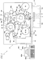
- This immunity analyzer 1 is mainly composed, as schematically shown in Fig. 1 , of a measurement unit (measurement section) 2 consisting of a plurality of mechanisms (components) ; and a control apparatus 400 (see Fig. 3 ) that is a data processing unit electrically connected to this measurement unit 2.
- the measurement unit 2 includes: a sample conveyor (sampler) 10; an emergency sample/chip conveyor 20; a pipette chip supply apparatus 30; a chip detachment section 40; a sample dispensing arm 50; a reagent installation sections 60a and 60b; a first-order reaction section 80a and a second-order reaction section 80b; reagent dispensing arms 90a, 90b, and 90c; a first BF separation section 100a and a second BF separation section 100b; a detector 120; and a main body controller 140 (see Fig. 2 ) for controlling the operations of mechanisms such as the sample conveyor (sampler) 10 and the sample dispensing arm 50.
- a disposable pipette chip is exchanged with the new one whenever a sample is sucked and discharged in order to restrain a sample (e.g., blood) sucked and discharged by the sample dispensing arm 50 from being mixed with other samples.
- a capture antibody (reagent R1) bound to an antigen included in a sample (e.g., blood) as a measurement target is allowed to be bound to magnetic particles (reagent R2) to prepare a complex of antigen-capture antibody-magnet particles.
- the complex of antigen-capture antibody-magnetic particles is attracted by a magnet of a first Bound Free (BF) separation section 100a, thereby removing the reagent R1 including unreacted (free) capture antibody.
- the antigen of the complex is bound to a labeled antibody (reagent R3) to prepare a complex of antigen-capture antibody-magnetic particles-labeled antibody.
- the complex of antigen-capture antibody-magnetic particles-labeled antibody is attracted by a magnet of a second BF separation section 100b, thereby removing the reagent R3 including an unreacted (free) labeled antibody.
- a luminescent substrate (reagent R5) that emits light in a process of the reaction with the labeled antibody is added to subsequently measure the light emission amount caused by the reaction between the labeled antibody and the luminescent substrate.
- the control apparatus 400 is composed of a personal computer 401 (PC) for example. As shown in Fig. 1 , the control apparatus 400 includes: a controller 400a; a display section 400b; and an input section (input means) 400c such as a keyboard or a mouse.
- the controller 400a has a function to control the operations of the respective mechanisms in the measurement unit 2 and to analyze the optical information for the sample obtained by the measurement unit 2.
- This controller 400a is composed of CPU, ROM, and RAM for example.
- the display section 400b is used to display the information for the analysis result obtained by the controller 400a or to display an error window (measurement section help window) 210 (which will be described later) or the like.
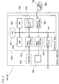
- the controller 400a is mainly composed of: a CPU 401a; a memorization section consisting of a ROM 401b, a RAM 401c, and a hard disk 401d or the like; a reading apparatus 401e; an input/output interface 401f; a communication interface 401g; and an image output interface 401h.
- the CPU 401a, the ROM 401b, the RAM 401c, the hard disk 401d, the reading apparatus 401e, the input/output interface 401f, the communication interface 401g, and the image output interface 401h are connected by a bus 401i.
- the CPU 401a can execute a computer program memorized in the ROM 401b and a computer program loaded to the RAM 401c. By allowing the CPU 401a to execute an application program 404a (which will be described later), the computer 401 functions as the control apparatus 400.
- the ROM 401b is composed of a mask ROM, PROM, EPROM, EEPROM or the like in which the computer program executed by the CPU 401a and the data used for this or the like are recorded.
- the RAM 401c is composed of a SRAM or DRAM or the like.
- the RAM 401c is used to read a computer program recorded in the ROM 401b and the hard disk 401d.
- the RAM 401c is also used as an operation region of the CPU 401a when these computer programs are executed.
- various computer programs 404a such as an operating system and an application program to be executed by the CPU 401a and data used to execute the computer programs are installed.
- an application program for registering a measurement order and an application program for acquiring or displaying the information for an error of the measurement unit 2 as will be described later are also installed in this hard disk 401d.
- the hard disk 401d memorizes an abnormal place image, an error details message, a background image of the apparatus status display area 202, and an error recovery icon that are associated with apparatus status and that will be described later.
- the reading apparatus 401e is composed of a flexible disk drive, a CD-ROM drive, a DVD-ROM drive or the like.
- the reading apparatus 401e can read a computer program or data recorded in a mobile recording medium 404.
- the mobile recording medium 404 stores therein the application program 404a in this embodiment.
- the computer 401 can read the application program 404a from the mobile recording medium 404 to install the application program 404a in the hard disk 401d.
- the application program 404a can be provided not only from the mobile recording medium 404 but also from an external device connected to the computer 401 to have communication therebetween via an electric communication line (which may be wired or wireless) .
- the application program 404a also can be stored in a hard disk of a server computer on the Internet and the computer 401 may access this server computer to download the application program 404a to install the application program 404a in the hard disk 401d.
- an operating system providing a graphical user interface environment such as Windows® manufactured and sold by Microsoft Corporation is installed for example.
- the following description assumes that the application program 404a in this embodiment operates on the operating system.
- the input/output interface 401f is composed, for example, of a serial interface such as a USB, IEEE1394 or RS-232C, a parallel interface such as an SCSI, IDE or IEEE1284, and an analog interface comprising a D/A converter, an A/D converter or the like.
- the input/output interface 401f is connected to the keyboard 400c. A user can use the keyboard 400c to input data to the computer 401.
- the communication interface 401g is an Ethernet® interface for example.
- the computer 401 can use the communication interface 401g to use a predetermined communication protocol to send data to and to receive data from the measurement unit 2.
- the image output interface 401h is connected to the display section 400b composed of a LCD, a CRT or the like.
- the image output interface 401h is structured to output, to the display section 400b, a video signal depending on image data given from the CPU 401a. Based on the inputted video signal, the display section 400b displays an image (screen).
- the respective mechanisms of the immunity analyzer 1 may use a known configuration. The following section will describe the configurations of the respective mechanisms of the immunity analyzer 1.
- a sample conveyor 10 is configured to transport a rack 4 holding a plurality of test tubes 3 accommodating samples to a position corresponding to the sucking position of the sample dispensing arm 50.
- This sample conveyor 10 has: a rack setting section 10a for setting the rack 4 holding the test tubes 3 accommodating unprocessed samples; and a rack reservoir 10b for reserving the rack 4 holding the test tube 3 accommodating samples already subjected to the dispensing processing.
- the sample conveyor 10 transports the test tube 3 accommodating unprocessed samples to the position corresponding to the sucking position of the sample dispensing arm 50.
- the samples e.g., blood
- the rack 4 holding the test tube 3 is reserved by the rack reservoir 10b.
- An emergency sample/chip conveyor 20 is configured to transport, to the attachment position of the sample dispensing arm 50, the test tube 3 accommodating an emergency sample that must be inspected prior to samples transported by the sample conveyor 10.
- a pipette chip supply apparatus 30 has a function to place inputted pipette chips one by one in a chip installation section 23a of a transport rack 23 of the emergency sample/chip conveyor 20.
- a chip detachment section 40 is provided to disengage a pipette chip attached to the sample dispensing arm 50 (which will be described later).
- the sample dispensing arm 50 has a function to dispense the samples in the test tube 3 transported by the sample conveyor 10 to the sucking position into cuvettes (not shown) retained in a retaining section 81a of a rotary table section 81 of a first-order reaction section 80a which will be described later.
- This sample dispensing arm 50 is configured to rotate an arm section 51 around an axis 52 and to move the arm section 51 in an up-and-down direction (direction Z).
- a nozzle section for sucking and discharging samples is provided at a tip end of this nozzle section is attached with a pipette chip transported by a transport rack (not shown) of the emergency sample/chip conveyor 20.
- a reagent installation section 60a includes a reagent container accommodating the reagent R1 including a capture antibody and a reagent container accommodating the reagent R3 including a labeled antibody.
- a reagent installation section 60b includes a reagent container accommodating the reagent R2 including magnetic particles.
- the first-order reaction section 80a is provided to transfer the cuvette retained by the retaining section 81a of the rotary table section 81 while rotating the cuvette by a predetermined angle whenever a predetermined period (20 seconds in this embodiment) is reached to agitate the sample, the reagent R1 and the reagent R2 in the cuvette.
- the first-order reaction section 80a is provided to cause, in the cuvette, the reagent R1 having capture antibody to react with the antigen in the sample, and the reagent R1 having capture antibody to react with the reagent R2 having magnetic particles.
- This first-order reaction section 80a is composed of: the rotary table section 81 for transporting the cuvette accommodating the sample, the reagent R1, and the reagent R2 in the rotating direction; and a container conveyor 82 for agitating the sample, the reagent R1, and the reagent R2 in the cuvette 8 and transporting the cuvette 8 accommodating the agitated sample, the reagent R1, and the reagent R2 to a first BF separation section 100a (which will be described later).
- the container conveyor 82 is provided at the center of the rotary table section 81 in a rotatable manner.
- This container conveyor 82 has a function to grasp the cuvette retained by the retaining section 81a of the rotary table section 81 and to agitate the sample in the cuvette.
- the container conveyor 82 also has a function to transport, to the first BF separation section 100a, a cuvette accommodating a sample obtained by agitating the sample, the reagent R1, and the reagent R2 to incubate the mixture.
- a reagent dispensing arm 90a has a function to suck the reagent R1 in a reagent container provided in the reagent installation section 60a to dispense the sucked reagent R1 into the cuvette of the first-order reaction section 80a.
- This reagent dispensing arm 90a is configured to rotate an arm section 91b around an axis 91c and to move the arm section 91b in the up-and-down direction.
- a tip end of the arm section 91b is attached with a nozzle for sucking and discharging the reagent R1 in the reagent container.
- a reagent dispensing arm 90b has a function to dispense the reagent R2 in the reagent container provided in the reagent installation section 60b into the cuvette of the first-order reaction section 80a in which the sample and the reagent R1 are dispensed.
- This reagent dispensing arm 90b is configured so that an arm section 92b can be rotated around an axis 92c and can be moved in the up-and-down direction (direction Z).
- a tip end of the arm section 92b is attached with a nozzle for sucking and discharging the reagent R2 in the reagent container.
- the first BF separation section 100a is provided to isolate the unreacted reagent R1 (unnecessary component) and magnetic particles from the sample in the cuvette transported by the container conveyor 82 of the first-order reaction section 80a.
- the cuvette of the first BF separation section 100a accommodating the isolated unreacted reagent R1 or the like is transported by a transport mechanism 96 to a retaining section 83a of a rotary table section 83 of a second-order reaction section 80b.
- the transport mechanism 96 is configured to rotate an arm section 96a having a cuvette grasp section (not shown) at a tip end around an axis 96b and to move the arm section 96a in the up-and-down direction (direction Z).
- the second-order reaction section 80b has the same configuration as that of the first-order reaction section 80a.
- the second-order reaction section 80b is provided to rotate the cuvette retained by the retaining section 83a of the rotary table section 83 by a predetermined angle whenever a predetermined period (20 seconds in this embodiment) is reached to transfer the cuvette and to agitate the complex of antigen-capture antibody-magnetic particles, the reagent R3, and the reagent R5 in cuvette.
- the second-order reaction section 80b is provided to cause, in the cuvette, the reagent R3 having the labeled antibody to react with the antigen in the sample and to cause the reagent R5 having the luminescent substrate to react with the labeled antibody of the reagent R3.
- This second-order reaction section 80b is composed of: the rotary table section 83 for transporting the cuvette 8 accommodating the sample, the reagent R1, the reagent R2 , the reagent R3, and the reagent R5 in the rotating direction; and a container conveyor 84 for agitating the sample, the reagent R1, the reagent R2, the reagent R3, and the reagent R5 in the cuvette and transporting the cuvette accommodating the agitated sample or the like to the second BF separation section 100b (which will be described later) .
- the container conveyor 84 also has a function to transport the cuvette processed by the second BF separation section 100b to the retaining section 83a of the rotary table section 83 again.
- the reagent dispensing arm 90c has a function to suck the reagent R3 in the reagent container provided in the reagent installation section 60a to dispense the sucked reagent R3 to the cuvette of the second-order reaction section 80b in which the sample, the reagent R1 and the reagent R2 are dispensed.
- This reagent dispensing arm 90c is configured to rotate an arm section 93b around an axis 93c and move the arm section 93b in the up-and-down direction.
- a tip end of the arm section 93b is attached with a nozzle for sucking and discharging the reagent R3 in the reagent container.
- the second BF separation section 100b has the same configuration as that of the first BF separation section 100a.
- the second BF separation section 100b is provided to isolate the unreacted reagent R3 (unnecessary component) and magnetic particles from the sample in the cuvette transported by the container conveyor 84 of the second-order reaction section 80b.
- a reagent R4 supply section 94 and a reagent R5 supply section 95 are provided to supply the reagent R4 and the reagent R5 to the cuvette retained by the retaining section 83a of the rotary table section 83 of the second-order reaction section 80b, respectively.
- a detector 120 is provided to obtain, through a photo multiplier tube, the light caused by the reaction process between a labeled antibody bound to the antigen of the sample subjected to a predetermined processing and the luminescent substrate to measure the amount of the antigen included in the sample.
- This detector 120 includes a transport mechanism section 121 to transport the cuvette retained by the retaining section 83a of the rotary table section 83 of the second-order reaction section 80b to the detector 120.
- a used cuvette from which a measured sample is already sucked is disposed, via a disposal hole 130, in a dust box (not shown) provided at the lower part of the immunity analyzer 1.
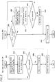
- Fig.4 The flow of the entirety of the analysis processing by the immunity analyzer 1 is shown in Fig.4 . It is noted that the processing which will be described hereinafter is a processing controlled by the controller 400a and the main body controller 140.
- Step S1 when the power source of the immunity analyzer 1 is turned ON, the main body controller 140 is initialized (Step S1). In this initialization operation, the program is initialized and the driving part of the immunity analyzer 1 is returned to the original position for example.
- Step S101 When the power source of a personal computer 401 connected to the immunity analyzer 1 so as to have communication therebetween is turned ON, the controller 400a of the personal computer 401 is initialized (Step S101). This initialization operation initializes a program for example.
- Step S102 determines whether an instruction for the start of the measurement is issued or not.
- the processing proceeds to Step S103.
- the controller 400a determines that the instruction for the start of the measurement is not issued (No)
- the processing proceeds to Step S113.
- Step S103 allows a measurement start signal to be sent from the controller 400a to the main body controller 140.
- Step 2 determines whether the reception of a measurement start signal is performed or not.
- the processing proceeds to Step S3.
- the main body controller 140 determines that the reception of a measurement start signal is not performed (No)
- the processing proceeds to Step S14.
- the rack 4 holding a plurality of test tubes 3 accommodating samples is transported by the sample conveyor 10 in Step S3 to a position corresponding to the sucking position 1a of the sample dispensing arm 50.
- the rack 4 is given with a bar code as a recording section on which information (rack number) for identifying the rack 4 is recorded.
- the bar code is read by a detector (not shown) provided in a transport path through which the rack 4 is transported to a predetermined position (Step S4).
- the read rack number is transmitted by the main body controller 140 in Step S5 to the personal computer 401.
- Step S104 determines whether the reception of the rack number is performed or not.
- the processing proceeds to Step S105.
- Step S105 allows the controller 400a to search an order page. Specifically, the controller 400a searches the order information corresponding to the rack number received in Step S104 from among the order information memorized in the memorization region of the hard disk 401d.
- the test tube 3 is given with a bar code that is a recording section on which the information (sample number) for identifying the sample in the test tube 3 is recorded.
- the bar code is read by a detector (not shown) provided in a transport path through which the rack 4 holding the test tube 3 is transported to a predetermined position (Step S6).
- the read sample number is sent in Step S7 to the personal computer 401. It is noted that the bar code of the test tube 3 and the bar code of the rack 4 may be read by different detectors or may be read by a common detector.
- Step S106 allows the controller 400a to determine whether the reception of the sample number is performed or not.
- the processing proceeds to Step S107.
- Step S107 allows the controller 400a to search the order. Specifically, the controller 400a searches the order information corresponding to the sample number received in Step S106 from among the order information corresponding to the specific rack number searched in Step S105. Then, Step S108 allows the controller 400a to send the order instruction to the main body controller 140.
- Step S8 allows the main body controller 140 to determine whether the reception of the order instruction is performed or not.
- the processing proceeds to Step S9.
- Step S9 carries out the measurement of the ordered item. Then, the measurement result is sent by the main body controller 140 to the personal computer 401 (Step S10) .
- Step S109 allows the controller 400a to determine whether the reception of the measurement result is performed or not.
- the processing proceeds to Step S110.
- Step S110 subjects the measurement result sent from the main body controller 140 to an analysis processing. Specifically, based on the transmitted measurement result and a calibration curve that is prepared by a standard sample in advance and that is memorized in the hard disk 401d, the controller 400a calculates the concentration of the antigen of the measurement target to memorize the result (analysis result) . The controller 400a outputs the analysis result.
- Step S111 allows the controller 400a to determine whether the samples in the test tubes 3 held by the rack 4 are all measured or not.
- the processing proceeds to Step S112.
- the controller 400a determines that not all of the samples in the test tubes 3 held by the rack 4 are measured (No)
- the processing returns to Step S106.
- Step S112 allows the controller 400a to determine whether all of the racks 4 are measured or not.
- the processing proceeds to Step S113.
- the processing returns to Step S104.
- Step S113 allows the controller 400a to determine whether an instruction to shut down the personal computer 401 is accepted or not.
- the processing proceeds to Step S114.
- the controller 400a determines that an instruction to shut down the personal computer 401 is not accepted (No)
- the processing returns to Step S102.
- Step S114 allows the shutdown signal to be sent from the controller 400a to the main body controller 140.
- Step S115 allows the controller 400a to shut down the personal computer 401, thereby completing the processing.
- Step S11 allows the main body controller 140 to determine whether the samples in the test tubes 3 held by the rack 4 are all measured or not.
- the processing proceeds to Step S13.
- the rack 4 is transported by a predetermined distance (a distance along which a test tube accommodating a sample to be measured next reaches a to-be-sucked position) (Step S12). Then, the processing returns to Step S6.
- Step S13 allows the main body controller 140 to determine whether all of the racks 4 are measured or not.
- the processing proceeds to Step S14.
- the main body controller 140 determines that not all of the racks 4 are measured (No)
- the processing returns to Step S3.
- Step S14 allows the main body controller 140 to determine whether the reception of the shutdown signal is performed or not.
- the processing proceeds to Step S15.
- the main body controller 140 determines that the reception of the shutdown signal is not performed (No)
- the processing returns to Step S2.
- Step S15 allows the main body controller 140 to shut down the immunity analyzer 1, thereby completing the processing.
- Fig. 5 is a flowchart illustrating the operation status check processing of the immunity analyzer 1.
- the respective mechanisms (components) constituting the measurement unit 2 such as the sample conveyor 10, the sample dispensing arm 50, and the reagent dispensing arms 90a to 90c include sensors 10s, 20s, 30s, 40s, 50s, 60s, 80sa, 80sb, 90s, 100s and 120s (sensing means) for monitoring the operation situations of the respective mechanisms (See Fig.2 ).
- the main body controller 140 acquires the detection results from the respective sensors.
- the main body controller 140 analyzes the detection results (operation status information) acquired from the respective sensors. When an error occurs, the error is detected by this processing for analyzing the operation status.
- Step S303 allows the main body controller 140 to determine whether the error is detected or not.
- the processing returns to Step S301.
- error information is read in Step S304. This error information is information identifying the error (error ID). Then, the main body controller 140 in Step S305 sends the error information to the controller 400a, thereby completing the processing.
- Step S401 allows the controller 400a to determine whether the error information is received or not.
- the processing proceeds to Step S406 and an error processing (which will be described later) is executed.
- the controller 400a in Step S402 acquires the operation status information of the control apparatus 400.
- This operation status information includes software internal status information and status information for hardware such as a communication interface.
- the controller 400a in Step S403 analyzes the acquired operation status information.
- Step S404 allows the controller 400a to determine whether the error is detected or not.
- the processing returns to Step S401.
- the controller 400a in Step S404 determines that the error is detected, the error information is read in Step S405.
- the controller 400a executes an error processing (which will be described next) (Step S406), thereby completing the processing.
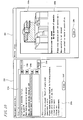
- this error processing is performed by providing a predetermined display on the apparatus status display area 202 of the main window 201 displayed on the display section 400b and by newly displaying a measurement section help window (error window) 210 on the display section 400b.
- the main window 201 is a window displayed in the display section 400b when an application program for controlling the measurement unit 2 is activated.
- the main window 201 has a title bar 201a, a menu bar 201b, a tool bar 201c, a main display block 201d, and an auxiliary display block 201e.
- an order registration screen is displayed in the main display block 201c.
- the auxiliary display block 201d includes an apparatus status display area 202, a message display area 203, and a consumable supply information display area 204.
- the measurement section help window 210 is displayed in the main display block 201c of the main window 201 so as to be superposed on the previously-displayed screen.
- the hard disk 401d of the controller 400a memorizes information regarding forms of various errors that may occur in the apparatus. Specifically, the hard disk 401d of the controller 400a memorizes pieces of information such as error titles (brief description of the errors), error-occurring places, and methods for recovering the errors so that the pieces of information are associated to one another.
- the information for the error-occurring place includes information for an image representing the place in a three-dimensional or two-dimensional manner (diagram, photograph, picture).
- Fig. 6 is a flowchart illustrating the error processing by the controller 400a.
- the controller 400a performs a processing for reading, from the hard disk 401d, an error title, an action message, and an error recovery icon corresponding to the detected error.
- the action message is mainly information regarding the method for recovering the error, and represents a procedure for recovering the error by a text.
- the error recovery icon 220 is similarly information regarding the method for recovering the error. As shown in Fig. 7 , the error recovery icon 220 simply shows an operation that should be performed by a user in order to recover the error.
- Step S412 of Fig. 6 the controller 400a displays the apparatus status display area 202 by the display color corresponding to the detected error (which is shown by a dotted line hatching in Fig. 7 and the details of the display color will be described later) .
- the error recovery icon 220 is displayed in the apparatus status display area 202.
- the measurement section help window 210 as shown in Fig. 7 is displayed on the main window 201 (Step S413). Alarm sound is also generated together with the display of the measurement section help window 210.
- an error list (error title display area) 210a is provided.
- This error list 210a displays one or a plurality of detected error title(s). In the example shown in Fig. 7 , the error list 210a displays seven error titles listed in the up-and-down direction. This error list 210a displays error titles in an order of priority.
- a button 210b for scrolling the error titles is provided.
- an action display area (recovery operation display area) 210c is provided at the lower side of the measurement section help window 210. This action display area 210c displays an action message corresponding to the error title selected in the error list 210a.
- an error title at the top of the error list 210a is selected and an action message corresponding to the error title is displayed in the action display area 210c.
- an action message corresponding to the error title is displayed in the action display area 210c.
- the controller 400a in Step S414 of Fig. 6 determines whether the selection of another error title in the error list 210a is accepted or not. When the controller 400a determines that the selection of another error title in the error list 210a is accepted (Yes), the processing proceeds to Step S415. When the controller 400a determines that the selection of another error title in the error list 210a is not accepted (No), the processing proceeds to Step S416. The controller 400a in Step S415 displays an action message corresponding to the newly-selected error title in the action display area 210c.
- the user can read the error title and the action message displayed in the measurement section help window 210 to perform an operation based on the procedure displayed in the action message, thereby recovering the error.
- the user also can select an alarm reset button 210d to stop the alarm sound.
- the apparatus status display area 202 displays the word "error” and also displays two error recovery icons 220a and 220b.
- the error recovery icon 220a is a "rack reset icon” instructing the reset of the rack 4.
- the error recovery icon 220b is a "measurement start icon” instructing the selection of the measurement start button 204 displayed at the upper-right part of the main window 201.
- the user can reset the rack 4 to the sample conveyor 10 and can select (or click) the measurement start button 204 of the main window 201 to resume the measurement. Specifically, the user can perform an operation based on the error recovery icon 220 displayed as an image in the apparatus status display area 202 to recover from the error status.
- the image of the error recovery icon 220 is designed so as to allow the user to recognize how to operate.
- the rack reset icon 220a is composed of a simple image schematically showing the rack 4 and an arrow showing the reset of the rack 4. The user can see the design of this image to associate the image with an operation that should be performed.
- the measurement start icon 220b has the same design as that of the measurement start button 204. Thus, the user can search and select a button having the same image as that of the measurement start icon 220b and thus is prevented from performing a wrong operation such as a case where the user mistakenly selects a wrong button.
- the controller 400a can perform an operation for an error processing by displaying an abnormal place dialogue 230 (see Fig. 8 ) in addition to the measurement section help window 210.
- this abnormal place dialogue 230 is a window that is newly activated when the "abnormal place" button 210e in the measurement section help window 210 is selected (or clicked).
- the abnormal place dialogue 230 can be optionally displayed when the user cannot recognize the error place only based on the contents displayed in the measurement section help window 210 or when the user wants to know detailed information for the error.
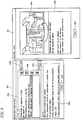
- Fig. 8 shows the measurement section help window 210 having different contents from those shown in Fig. 7 and an abnormal place dialogue 230 corresponding to this measurement section help window 210.
- an error title of "abnormal communication with host computer” is selected in the error list of the measurement section help window 210 and the corresponding action message of recovery information is displayed in the action display area 210c saying "Connection setting to host computer is OFF. Please change the setting to ON when the host computer has no problem".
- the abnormal place dialogue 230 As shown at the right side is activated.
- the error place display area 230a displaying the error-occurring place by an image is provided.
- the error place display area 230a displays, by a three-dimensional image, a relation between the control apparatus 400 (IPU) and a host computer (HOST) connected to this control apparatus 400 so as to establish communication therebetween.
- a detailed contents display area 230b is provided to display the detailed contents for an error (e.g., a cause of the error).
- the controller 400a in Step S416 of Fig. 6 determines whether the user has selected the abnormal place button 210e of the measurement section help window 210 or not (i.e., whether an instruction for displaying the abnormal place dialogue 210e is accepted or not).
- the controller 400a determines that the instruction for displaying the abnormal place dialogue 230 is accepted (Yes)
- the controller 400a allows the processing to proceed to Step S417.
- the processing proceeds to Step S421.
- Step S417 allows the controller 400a to read, from the hard disk 401d, the abnormal place image and the error details message corresponding to the error title selected in the error list 210a.
- Step S418 allows the controller 400a to display the abnormal place dialogue 230.
- the user can visually recognize a place at which the error occurs. Specifically, when a user having a small operation experience cannot sufficiently understand the error-occurring place only based on the action message of the measurement section help window 210, the abnormal place dialogue 230 can be displayed to allow the user to accurately recognize the error-occurring place to recover the error. The user also can read the error details message displayed in the detailed contents display area 230b to obtain more detailed information for the error.
- Fig. 9 shows the measurement section help window 210 according to another example and the abnormal place dialogue 230 corresponding to this measurement section help window 210.
- an error title of "sample sucking sensor is abnormal" is selected in the error list 210a of the measurement section help window 210, and as the corresponding action message there is displayed, by text, the operation details for the measurement unit 2 regarding the error and a procedure for recovering the error.
- the abnormal place button 210e the abnormal place dialogue 230 is displayed.
- the error place display area 230a displays a three-dimensional image having the sample sucking portion (sample dispensing arm 50) at the center.
- the detailed contents display area 230b displays the cause of the error and how to do if the error is not recovered for example.
- the error place display area 230a displays the error place with a remarkable color (e.g., red, which is shown by hatching).
- Fig. 10 shows the measurement section help window 210 according to a still another example and the abnormal place dialogue 230 corresponding to this the measurement section help window 210.
- an error title of "operation cover is open.” is selected in the error list 210a of the measurement section help window 210, and as the corresponding action message there is displayed, by text, the operation details for the measurement unit 2 regarding the error and a procedure for recovering the error.
- the abnormal place button 210e the abnormal place dialogue 230 is displayed.
- the error place display area 230a displays a three-dimensional image having the operation cover of the measurement section unit 2 at the center.
- the detailed contents display area 230b displays the cause of the error and how to do if the error is not recovered for example.
- the error place display area 230a displays the error place with a remarkable color (which is shown by hatching).
- Step S419 of Fig. 6 determines whether the user has selected the "close” button 230c of the abnormal place dialogue or not (i.e., whether an instruction for not displaying the abnormal place dialogue 230 is accepted or not).
- the controller 400a allows the processing to proceed to Step S420 to carry out a processing to prevent the abnormal place dialogue 230 from being displayed (or to close the abnormal place dialogue 230).
- Step S421 determines whether an operation (processing) required for the error recovery is performed or not.
- the processing proceeds to Step S422.
- Step S422 allows the controller 400a to delete the title of the recovered error from the error list 210a of the measurement section help window 210.
- Step S423 allows the controller 400a to optionally switch the display color of the apparatus status display area 202 (see Fig. 7 ) and to prevent the corresponding error recovery icon 220 from being displayed and the processing returns to Step S414.
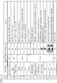
- Fig. 11 is a table showing, with regard to the apparatus status display area 202 shown in Fig. 7 , the text displays, the display colors, the error recovery icons, and the apparatus statuses that associated to one another.
- the apparatus status display area 202 of the main window 201 displays the character information (text) showing the apparatus status of the measurement unit 2.
- the color of the entire area 202 in accordance with the apparatus status is switched to gray, blue, green, yellow, or red.
- the text data shown in the apparatus status display area 202, the background images of the apparatus status display area 202 of the respective display colors, and the error recovery icons are set in advance and are memorized in the hard disk 401d of the controller 400a so as to be associated to one another.
- the color of the apparatus status display area 202 is "gray” when the power source of the measurement unit 2 is in an OFF status and the measurement cannot be performed (No.1).
- the color of the apparatus status display area 202 is "blue” when the power source of the measurement unit 2 is ON but the measurement cannot be performed immediately (due to a pause status, a sleep status or the like) (No.2 and No.3) .
- the color of the apparatus status display area 202 is "green” when the measurement unit 2 does not perform a measurement operation but the measurement can be started soon (No.4 to No.6).
- the color of the apparatus status display area 202 is "yellow” when the measurement unit 2 is performing a measurement operation, an initial operation, a maintenance operation (No.7 to No.14).
- the color of the apparatus status display area 202 is "red" when a fatal error occurs during the measurement and thus measurement cannot be performed (No.15).
- the background images of the apparatus image display area 202 of the respective display colors associated with the respective apparatus statuses are memorized in the hard disk 401d.
- the above-described error recovery icon 220 (see Fig. 7 ) is displayed in the apparatus status display area 202.
- an interruption button 205 (see Fig. 7 ) is depressed during the operation of the measurement unit 2 for example, the sucking of a new sample is stopped while an already-sucked sample being measured.
- the yellow background image is displayed in the apparatus status display area 202 and the text of "being interrupted” is displayed and a "measurement start icon" 220b is displayed as the error recovery icon 220.
- the user can select the measurement start button 204 (see Fig. 7 ) in accordance with the measurement start icon 220b to resume the measurement.
- the measurement can be resumed only by selecting the measurement start button 204 and thus only the "measurement start icon" 220b is displayed in the apparatus status display area 202.
- the measurement can be resumed by resetting the rack to subsequently select the measurement start button 204 and thus both of the "rack reset icon” 220a and the “measurement start icon” 220b are displayed.
- the rack 4 must be reset but the measurement start button 204 cannot be selected.
- the "rack reset icon" 220a and the "measurement start impossible icon” (which is represented by adding symbol ⁇ to the measurement start icon) are displayed.
- the color depending on the apparatus status of the measurement unit 2 is given to the apparatus status display area 202.
- the user can recognize, at a glance, whether the measurement unit 2 can be operated or not, or whether the measurement unit 2 already operates or not, for example.
- the present invention is not limited to the above embodiment and also can be appropriately applied to different designs.
- the abnormal place dialogue 230 and the measurement section help window 210 can be simultaneously displayed in the display section 400a or also may be integrated to one window.
- the present invention is not limited to the immunity analyzer and also can be used for other analysis apparatuses such as a blood coagulation analyzer, a multiple blood cell analysis apparatus, a formed urine component analysis apparatus, and a gene amplification measurement apparatus.
Landscapes
- Engineering & Computer Science (AREA)
- Theoretical Computer Science (AREA)
- Quality & Reliability (AREA)
- Physics & Mathematics (AREA)
- General Physics & Mathematics (AREA)
- General Engineering & Computer Science (AREA)
- Health & Medical Sciences (AREA)
- Life Sciences & Earth Sciences (AREA)
- Chemical & Material Sciences (AREA)
- Analytical Chemistry (AREA)
- Biochemistry (AREA)
- General Health & Medical Sciences (AREA)
- Immunology (AREA)
- Pathology (AREA)
- Automatic Analysis And Handling Materials Therefor (AREA)
Claims (12)
- Analyseur d'échantillon pour analyser un échantillon, comprenant :une section de mesure (2) adaptée pour mesurer l'échantillon et incluant un capteur (10s, 20s, 30s, 40s, 50s, 60s, 80sa, 80sb, 90s, 100s, 120s) adapté pour détecter l'état de l'analyseur d'échantillon incluant un état d'erreur ;un écran (400b) ; etun dispositif de commande (401a) adapté pour commander l'écran de manière à afficher une fenêtre d'aide de section de mesure (210) quand le capteur (10s, 20s, 30s, 40s, 50s, 60s, 80sa, 80sb, 90s, 100s, 120s) détecte l'état d'erreur,dans lequel la fenêtre d'aide de section de mesure (210) est adaptée pour afficher des informations de récupération pour récupérer l'analyseur d'échantillon à partir de l'état d'erreur, caractérisé en ce que la fenêtre d'aide de section de mesure (210) est en outre adaptée pour afficher un bouton de site anormal (210e),le dispositif de commande (410a) est adapté pour commander l'écran de manière à afficher un dialogue de site anormal (230) avec la fenêtre d'aide de section de mesure (210) quand le bouton de site anormal (210e) est sélectionné, etle dialogue de site anormal (230) est adapté pour afficher une image de site de survenue d'erreur concernant un site de survenue d'erreur où l'état d'erreur est survenu.
- Analyseur d'échantillon selon la revendication 1, comprenant en outre
une mémoire (401b, 401c, 401d) adaptée pour stocker les informations de récupération et l'image de site de survenue d'erreur,
dans lequel le dispositif de commande (401a) est adapté pour lire, à partir de la mémoire (401b, 401c, 401d), les informations de récupération et l'image de site de survenue d'erreur correspondant à l'état d'erreur détecté par le capteur (10s, 20s, 30s, 40s, 50s, 60s, 80sa, 80sb, 90s, 100s, 120s), et est adapté pour commander l'écran (400b) de manière à afficher les informations de récupération et l'image de site de survenue d'erreur lues à partir de la mémoire (401b, 401c, 401d). - Analyseur d'échantillon selon la revendication 1 ou la revendication 2, dans lequel l'image de site de survenue d'erreur affichée sur l'écran (400b) comprend une image montrant un site dans la section de mesure (2) où l'état d'erreur est survenu.
- Analyseur d'échantillon selon la revendication 3, dans lequel l'image de site de survenue d'erreur comprend un dessin extérieur de la section de mesure (2) incluant une unité où l'état d'erreur est survenu ; et
dans lequel l'unité est affichée de manière à pouvoir être distinguée d'autres unités de la section de mesure (2). - Analyseur d'échantillon selon l'une quelconque des revendications 1 à 4, dans lequel le dispositif de commande (401a) est adapté pour commander l'écran (400b) de manière à afficher une couleur d'affichage selon l'état de l'analyseur d'échantillon détecté par le capteur (10s, 20s, 30s, 40s, 50s, 60s, 80sa, 80sb, 90s, 100s, 120s).
- Analyseur d'échantillon selon l'une quelconque des revendications 1 à 5, dans lequel le dispositif de commande (401a) est adapté pour commander l'écran (400b) de manière à afficher une image d'icône montrant une procédure de récupération pour récupérer l'analyseur d'échantillon à partir de l'état d'erreur, quand le capteur (10s, 20s, 30s, 40s, 50s, 60s, 80sa, 80sb, 90s, 100s, 120s) détecte l'état d'erreur.
- Analyseur d'échantillon selon la revendication 2,
dans lequel la mémoire (401b, 401c, 401d) est adaptée pour stocker l'image d'icône ; et
dans lequel le dispositif de commande (401a) est adapté pour lire, à partir de la mémoire (401b, 401c, 401d), l'image d'icône correspondant à l'état d'erreur détecté par le capteur (10s, 20s, 30s, 40s, 50s, 60s, 80sa, 80sb, 90s, 100s, 120s), et adapté pour commander l'écran (400b) de manière à afficher l'image d'icône lue. - Procédé d'affichage d'informations d'erreur d'un analyseur d'échantillon pour analyser un échantillon, comprenant les étapes de :(a) détection d'un état de l'analyseur d'échantillon incluant l'état d'erreur ; et(b) affichage, sur un écran (400b), d'une fenêtre d'aide de section de mesure (210) quand l'état d'erreur est détecté à l'étape (a), dans lequel la fenêtre d'aide de section de mesure (210) est adaptée pour afficher des informations de récupération pour récupérer l'analyseur d'échantillon à partir de l'état d'erreur,
caractérisé en ce que la fenêtre d'aide de section de mesure (210) est en outre adaptée pour afficher un bouton de site anormal (210e),(c) acceptation de la sélection du bouton de site anormal (210e), et(d) affichage d'un dialogue de site anormal (230) avec la fenêtre d'aide de section de mesure (210), dans lequel le dialogue de site anormal (230) affiche une image de site de survenue d'erreur concernant un site où l'état d'erreur est survenu. - Procédé selon la revendication 8,
dans lequel l'analyseur d'échantillon comprend une section de mesure (2) pour mesurer l'échantillon ; et
dans lequel l'image de site de survenue d'erreur affichée sur l'écran comprend une image montrant un site dans la section de mesure (2) où l'état d'erreur est survenu. - Procédé selon la revendication 9,
dans lequel l'image de site de survenue d'erreur comprend un dessin extérieur de la section de mesure incluant une unité où l'état d'erreur est survenu ; et
dans lequel l'unité est affichée de manière à pouvoir être distinguée d'autres unités de la section de mesure (2). - Procédé selon l'une quelconque des revendications 8 à 10, comprenant en outre une étape
(e) d'affichage d'une couleur d'affichage selon l'état de l'analyseur d'échantillon détecté à l'étape (a) sur l'écran. - Procédé selon l'une quelconque des revendications 8 à 11, comprenant en outre une étape
(f) d'affichage d'une image d'icône montrant une procédure de récupération pour récupérer l'analyseur d'échantillon à partir de l'état d'erreur, quand l'état d'erreur est détecté à l'étape (a).
Applications Claiming Priority (1)
| Application Number | Priority Date | Filing Date | Title |
|---|---|---|---|
| JP2007243428A JP5089307B2 (ja) | 2007-09-20 | 2007-09-20 | 検体分析装置 |
Publications (3)
| Publication Number | Publication Date |
|---|---|
| EP2040081A2 EP2040081A2 (fr) | 2009-03-25 |
| EP2040081A3 EP2040081A3 (fr) | 2015-04-01 |
| EP2040081B1 true EP2040081B1 (fr) | 2019-01-23 |
Family
ID=40002945
Family Applications (1)
| Application Number | Title | Priority Date | Filing Date |
|---|---|---|---|
| EP08016380.1A Active EP2040081B1 (fr) | 2007-09-20 | 2008-09-17 | Analyseur d'échantillon et procédé d'affichage des informations d'erreur |
Country Status (4)
| Country | Link |
|---|---|
| US (2) | US7707010B2 (fr) |
| EP (1) | EP2040081B1 (fr) |
| JP (1) | JP5089307B2 (fr) |
| CN (1) | CN101393226B (fr) |
Families Citing this family (38)
| Publication number | Priority date | Publication date | Assignee | Title |
|---|---|---|---|---|
| JP5137436B2 (ja) * | 2007-03-29 | 2013-02-06 | シスメックス株式会社 | 試料分析装置 |
| JP5171368B2 (ja) * | 2008-04-17 | 2013-03-27 | 株式会社日立ハイテクノロジーズ | 自動分析装置 |
| JP5143630B2 (ja) * | 2008-05-22 | 2013-02-13 | シスメックス株式会社 | 分析装置 |
| JP5183457B2 (ja) * | 2008-12-26 | 2013-04-17 | 株式会社日立ハイテクノロジーズ | 自動分析装置、その支援システム |
| JP5778887B2 (ja) * | 2009-05-29 | 2015-09-16 | シスメックス株式会社 | 検体処理装置 |
| CN101900720B (zh) | 2009-05-29 | 2014-09-10 | 希森美康株式会社 | 检体处理装置以及检体处理方法 |
| JP5778886B2 (ja) * | 2009-05-29 | 2015-09-16 | シスメックス株式会社 | 検体処理装置 |
| JP5496581B2 (ja) * | 2009-08-31 | 2014-05-21 | シスメックス株式会社 | 検体処理装置 |
| JP5372678B2 (ja) * | 2009-09-17 | 2013-12-18 | シスメックス株式会社 | 検体処理装置 |
| US9389238B2 (en) * | 2009-09-28 | 2016-07-12 | Hitachi High-Technologies Corporation | Automatic analyzing device, information display method thereof, and information display system |
| JP5366747B2 (ja) * | 2009-09-30 | 2013-12-11 | シスメックス株式会社 | 分析装置 |
| CN101738556B (zh) * | 2009-12-24 | 2012-08-29 | 卡斯柯信号有限公司 | 一种新型故障信息显示处理系统 |
| JP2011191204A (ja) * | 2010-03-15 | 2011-09-29 | Sysmex Corp | 臨床検査装置、臨床検査情報管理システム、及びコンピュータプログラム |
| JP5670129B2 (ja) * | 2010-09-10 | 2015-02-18 | シスメックス株式会社 | 検体処理装置および検体処理方法 |
| JP5727219B2 (ja) * | 2010-12-28 | 2015-06-03 | シスメックス株式会社 | 検体分析装置及び検体分析システム |
| JP5836595B2 (ja) * | 2011-01-07 | 2015-12-24 | 富士機械製造株式会社 | 生産システム |
| JP5792508B2 (ja) * | 2011-05-02 | 2015-10-14 | シスメックス株式会社 | 検体処理装置 |
| WO2012165229A1 (fr) | 2011-06-03 | 2012-12-06 | 株式会社日立ハイテクノロジーズ | Autoanalyseur |
| JP5877058B2 (ja) * | 2011-12-22 | 2016-03-02 | シスメックス株式会社 | 検体処理装置 |
| JP2013140103A (ja) * | 2012-01-05 | 2013-07-18 | Hitachi High-Technologies Corp | 自動分析装置 |
| CN103425119B (zh) | 2012-05-23 | 2018-10-19 | 株式会社堀场制作所 | 测试系统、设备管理装置和车辆性能测试系统 |
| JP5597673B2 (ja) * | 2012-05-23 | 2014-10-01 | 株式会社堀場製作所 | 車両性能試験システム |
| CN102999394A (zh) * | 2012-12-06 | 2013-03-27 | 大连奥林匹克电子城文豪电子经销处 | 一种计算机软件故障诊断及修复系统 |
| JP6064636B2 (ja) * | 2013-02-06 | 2017-01-25 | 株式会社リコー | 情報処理システム、情報処理装置、認証方法及びプログラム |
| US20160300027A1 (en) * | 2013-11-15 | 2016-10-13 | Radiometer Medical Aps | Operator-specific adaptation of a medical alalyzer user interface |
| JP5851637B2 (ja) * | 2015-02-16 | 2016-02-03 | シスメックス株式会社 | 検体処理装置および表示方法 |
| JP5864793B2 (ja) * | 2015-02-16 | 2016-02-17 | シスメックス株式会社 | 検体測定装置および表示方法 |
| JP5836516B2 (ja) * | 2015-02-16 | 2015-12-24 | シスメックス株式会社 | 検体処理装置および表示方法 |
| JP5894334B1 (ja) * | 2015-11-27 | 2016-03-30 | シスメックス株式会社 | 検体測定装置および表示方法 |
| JP5883193B2 (ja) * | 2015-11-27 | 2016-03-09 | シスメックス株式会社 | 検体測定装置および表示方法 |
| CN105550081A (zh) * | 2015-12-07 | 2016-05-04 | 广州视源电子科技股份有限公司 | 板卡错误的显示方法和系统 |
| US10331522B2 (en) | 2017-03-17 | 2019-06-25 | International Business Machines Corporation | Event failure management |
| JP7133911B2 (ja) * | 2017-07-14 | 2022-09-09 | 株式会社堀場製作所 | 検体分析装置 |
| JP7064365B2 (ja) * | 2018-03-29 | 2022-05-10 | シスメックス株式会社 | 検体分析装置のモニタリングデータの生成装置、検体分析装置、検体分析装置のモニタリングデータ生成システム、前記システムの構築方法、検体分析装置のモニタリングデータの生成方法及び検体分析装置のモニタリング方法 |
| JP6845199B2 (ja) * | 2018-09-28 | 2021-03-17 | シスメックス株式会社 | 表示方法、検体分析装置、コンピュータプログラムおよび記録媒体 |
| CN112345781B (zh) * | 2019-08-08 | 2024-03-08 | 深圳迈瑞生物医疗电子股份有限公司 | 一种样本检测系统 |
| EP3822725A1 (fr) * | 2019-11-15 | 2021-05-19 | General Electric Company | Systèmes et procédés de diagnostic d'un dispositif de fabrication additive |
| EP4232791A4 (fr) * | 2020-10-26 | 2024-04-17 | Siemens Healthcare Diagnostics Inc | Procédés de visualisation d?états d?échantillon et systèmes de laboratoire de diagnostic les incluant |
Family Cites Families (17)
| Publication number | Priority date | Publication date | Assignee | Title |
|---|---|---|---|---|
| JPH06118108A (ja) * | 1992-10-06 | 1994-04-28 | Matsushita Electric Ind Co Ltd | 電子部品実装機故障診断方法 |
| JP3063564B2 (ja) * | 1995-03-17 | 2000-07-12 | 株式会社日立製作所 | 自動分析装置 |
| JP3326054B2 (ja) * | 1995-09-05 | 2002-09-17 | 株式会社日立製作所 | 自動分析装置 |
| DE60042105D1 (de) * | 1999-11-30 | 2009-06-10 | Sysmex Corp | Qualitätskontrollmethode und -Gerät |
| US6442440B1 (en) * | 2000-06-24 | 2002-08-27 | Dade Behring Inc. | Computer interface module having a flat menu |
| JP3603019B2 (ja) * | 2000-12-15 | 2004-12-15 | 株式会社日立製作所 | 生化学自動分析装置 |
| JP3731807B2 (ja) * | 2001-08-16 | 2006-01-05 | 株式会社堀場製作所 | 分析装置および分析装置の表示装置 |
| JP4327392B2 (ja) * | 2001-12-05 | 2009-09-09 | シスメックス株式会社 | 生体試料分析装置 |
| JP2006071649A (ja) | 2001-12-05 | 2006-03-16 | Sysmex Corp | 生体試料分析装置 |
| JP3990944B2 (ja) * | 2002-06-28 | 2007-10-17 | 株式会社日立ハイテクノロジーズ | 自動分析装置 |
| JP4225852B2 (ja) * | 2003-07-17 | 2009-02-18 | シスメックス株式会社 | 分析システム |
| US7185288B2 (en) * | 2003-07-18 | 2007-02-27 | Dade Behring Inc. | Operator interface module segmented by function in an automatic clinical analyzer |
| JP2006071359A (ja) * | 2004-08-31 | 2006-03-16 | Sysmex Corp | 遠隔管理方法、遠隔管理システム、状態報告装置、および管理装置 |
| JP2006284380A (ja) * | 2005-03-31 | 2006-10-19 | Sysmex Corp | 分析装置 |
| JP5175213B2 (ja) * | 2005-12-22 | 2013-04-03 | ハネウェル・インターナショナル・インコーポレーテッド | 携帯用サンプル分析システム |
| US7661013B2 (en) * | 2006-01-13 | 2010-02-09 | Agilent Technologies, Inc. | System and method for error recovery |
| US7403721B2 (en) * | 2006-02-28 | 2008-07-22 | Kabushiki Kaisha Toshiba | Image forming apparatus, MFP and method of displaying jam removal guidance |
-
2007
- 2007-09-20 JP JP2007243428A patent/JP5089307B2/ja active Active
-
2008
- 2008-09-17 EP EP08016380.1A patent/EP2040081B1/fr active Active
- 2008-09-18 US US12/284,146 patent/US7707010B2/en active Active
- 2008-09-18 CN CN2008101612442A patent/CN101393226B/zh active Active
-
2010
- 2010-03-23 US US12/729,998 patent/US8335662B2/en not_active Expired - Fee Related
Non-Patent Citations (1)
| Title |
|---|
| None * |
Also Published As
| Publication number | Publication date |
|---|---|
| US20090082984A1 (en) | 2009-03-26 |
| CN101393226B (zh) | 2012-08-29 |
| US7707010B2 (en) | 2010-04-27 |
| CN101393226A (zh) | 2009-03-25 |
| US20100238043A1 (en) | 2010-09-23 |
| US8335662B2 (en) | 2012-12-18 |
| EP2040081A3 (fr) | 2015-04-01 |
| EP2040081A2 (fr) | 2009-03-25 |
| JP5089307B2 (ja) | 2012-12-05 |
| JP2009074887A (ja) | 2009-04-09 |
Similar Documents
| Publication | Publication Date | Title |
|---|---|---|
| EP2040081B1 (fr) | Analyseur d'échantillon et procédé d'affichage des informations d'erreur | |
| EP2040080B1 (fr) | Analyseur d'échantillons et procédé d'analyse d'échantillons | |
| JP5179890B2 (ja) | 試料分析装置 | |
| JP5377866B2 (ja) | 検体分析装置 | |
| JP3990944B2 (ja) | 自動分析装置 | |
| EP1975623A2 (fr) | Analyseur d'échantillon | |
| US8425839B2 (en) | Sample analyzer | |
| JP5183457B2 (ja) | 自動分析装置、その支援システム | |
| JP2008058129A (ja) | 自動分析装置 | |
| JP2012208099A (ja) | 検体分析装置 | |
| JP2009074901A (ja) | 検体分析装置 | |
| JP2011191204A (ja) | 臨床検査装置、臨床検査情報管理システム、及びコンピュータプログラム | |
| WO2016017291A1 (fr) | Dispositif d'analyse automatique | |
| JP5171352B2 (ja) | 免疫分析装置及び免疫分析方法 | |
| JP5331916B2 (ja) | 検体分析装置 | |
| WO2008050397A1 (fr) | Analyseur | |
| JP7329625B2 (ja) | 自動分析装置、自動分析装置の表示システム、および自動分析装置における表示方法 | |
| JP5108366B2 (ja) | 検体分析装置 | |
| JP5722406B2 (ja) | 検体分析装置 | |
| EP3892999B1 (fr) | Dispositif d'analyse automatique | |
| US20190204347A1 (en) | Automated analyzer and retesting instruction system |
Legal Events
| Date | Code | Title | Description |
|---|---|---|---|
| PUAI | Public reference made under article 153(3) epc to a published international application that has entered the european phase |
Free format text: ORIGINAL CODE: 0009012 |
|
| AK | Designated contracting states |
Kind code of ref document: A2 Designated state(s): AT BE BG CH CY CZ DE DK EE ES FI FR GB GR HR HU IE IS IT LI LT LU LV MC MT NL NO PL PT RO SE SI SK TR |
|
| AX | Request for extension of the european patent |
Extension state: AL BA MK RS |
|
| PUAL | Search report despatched |
Free format text: ORIGINAL CODE: 0009013 |
|
| AK | Designated contracting states |
Kind code of ref document: A3 Designated state(s): AT BE BG CH CY CZ DE DK EE ES FI FR GB GR HR HU IE IS IT LI LT LU LV MC MT NL NO PL PT RO SE SI SK TR |
|
| AX | Request for extension of the european patent |
Extension state: AL BA MK RS |
|
| RIC1 | Information provided on ipc code assigned before grant |
Ipc: G01N 35/00 20060101AFI20150223BHEP Ipc: G06F 11/32 20060101ALI20150223BHEP |
|
| 17P | Request for examination filed |
Effective date: 20150928 |
|
| RBV | Designated contracting states (corrected) |
Designated state(s): AT BE BG CH CY CZ DE DK EE ES FI FR GB GR HR HU IE IS IT LI LT LU LV MC MT NL NO PL PT RO SE SI SK TR |
|
| AKX | Designation fees paid |
Designated state(s): AT BE BG CH CY CZ DE DK EE ES FI FR GB GR HR HU IE IS IT LI LT LU LV MC MT NL NO PL PT RO SE SI SK TR |
|
| AXX | Extension fees paid |
Extension state: BA Extension state: RS Extension state: MK Extension state: AL |
|
| RIC1 | Information provided on ipc code assigned before grant |
Ipc: G06F 11/32 20060101ALI20180611BHEP Ipc: G01N 35/00 20060101AFI20180611BHEP Ipc: G06F 11/07 20060101ALI20180611BHEP |
|
| GRAP | Despatch of communication of intention to grant a patent |
Free format text: ORIGINAL CODE: EPIDOSNIGR1 |
|
| STAA | Information on the status of an ep patent application or granted ep patent |
Free format text: STATUS: GRANT OF PATENT IS INTENDED |
|
| INTG | Intention to grant announced |
Effective date: 20180830 |
|
| GRAS | Grant fee paid |
Free format text: ORIGINAL CODE: EPIDOSNIGR3 |
|
| GRAA | (expected) grant |
Free format text: ORIGINAL CODE: 0009210 |
|
| STAA | Information on the status of an ep patent application or granted ep patent |
Free format text: STATUS: THE PATENT HAS BEEN GRANTED |
|
| AK | Designated contracting states |
Kind code of ref document: B1 Designated state(s): AT BE BG CH CY CZ DE DK EE ES FI FR GB GR HR HU IE IS IT LI LT LU LV MC MT NL NO PL PT RO SE SI SK TR |
|
| REG | Reference to a national code |
Ref country code: GB Ref legal event code: FG4D |
|
| REG | Reference to a national code |
Ref country code: CH Ref legal event code: EP |
|
| REG | Reference to a national code |
Ref country code: AT Ref legal event code: REF Ref document number: 1091863 Country of ref document: AT Kind code of ref document: T Effective date: 20190215 |
|
| REG | Reference to a national code |
Ref country code: IE Ref legal event code: FG4D |
|
| REG | Reference to a national code |
Ref country code: DE Ref legal event code: R096 Ref document number: 602008058829 Country of ref document: DE |
|
| REG | Reference to a national code |
Ref country code: NL Ref legal event code: MP Effective date: 20190123 |
|
| PG25 | Lapsed in a contracting state [announced via postgrant information from national office to epo] |
Ref country code: NL Free format text: LAPSE BECAUSE OF FAILURE TO SUBMIT A TRANSLATION OF THE DESCRIPTION OR TO PAY THE FEE WITHIN THE PRESCRIBED TIME-LIMIT Effective date: 20190123 |
|
| PG25 | Lapsed in a contracting state [announced via postgrant information from national office to epo] |
Ref country code: NO Free format text: LAPSE BECAUSE OF FAILURE TO SUBMIT A TRANSLATION OF THE DESCRIPTION OR TO PAY THE FEE WITHIN THE PRESCRIBED TIME-LIMIT Effective date: 20190423 Ref country code: PL Free format text: LAPSE BECAUSE OF FAILURE TO SUBMIT A TRANSLATION OF THE DESCRIPTION OR TO PAY THE FEE WITHIN THE PRESCRIBED TIME-LIMIT Effective date: 20190123 Ref country code: LT Free format text: LAPSE BECAUSE OF FAILURE TO SUBMIT A TRANSLATION OF THE DESCRIPTION OR TO PAY THE FEE WITHIN THE PRESCRIBED TIME-LIMIT Effective date: 20190123 Ref country code: ES Free format text: LAPSE BECAUSE OF FAILURE TO SUBMIT A TRANSLATION OF THE DESCRIPTION OR TO PAY THE FEE WITHIN THE PRESCRIBED TIME-LIMIT Effective date: 20190123 Ref country code: PT Free format text: LAPSE BECAUSE OF FAILURE TO SUBMIT A TRANSLATION OF THE DESCRIPTION OR TO PAY THE FEE WITHIN THE PRESCRIBED TIME-LIMIT Effective date: 20190523 Ref country code: SE Free format text: LAPSE BECAUSE OF FAILURE TO SUBMIT A TRANSLATION OF THE DESCRIPTION OR TO PAY THE FEE WITHIN THE PRESCRIBED TIME-LIMIT Effective date: 20190123 Ref country code: FI Free format text: LAPSE BECAUSE OF FAILURE TO SUBMIT A TRANSLATION OF THE DESCRIPTION OR TO PAY THE FEE WITHIN THE PRESCRIBED TIME-LIMIT Effective date: 20190123 |
|
| REG | Reference to a national code |
Ref country code: AT Ref legal event code: MK05 Ref document number: 1091863 Country of ref document: AT Kind code of ref document: T Effective date: 20190123 |
|
| PG25 | Lapsed in a contracting state [announced via postgrant information from national office to epo] |
Ref country code: LV Free format text: LAPSE BECAUSE OF FAILURE TO SUBMIT A TRANSLATION OF THE DESCRIPTION OR TO PAY THE FEE WITHIN THE PRESCRIBED TIME-LIMIT Effective date: 20190123 Ref country code: IS Free format text: LAPSE BECAUSE OF FAILURE TO SUBMIT A TRANSLATION OF THE DESCRIPTION OR TO PAY THE FEE WITHIN THE PRESCRIBED TIME-LIMIT Effective date: 20190523 Ref country code: BG Free format text: LAPSE BECAUSE OF FAILURE TO SUBMIT A TRANSLATION OF THE DESCRIPTION OR TO PAY THE FEE WITHIN THE PRESCRIBED TIME-LIMIT Effective date: 20190423 Ref country code: HR Free format text: LAPSE BECAUSE OF FAILURE TO SUBMIT A TRANSLATION OF THE DESCRIPTION OR TO PAY THE FEE WITHIN THE PRESCRIBED TIME-LIMIT Effective date: 20190123 Ref country code: GR Free format text: LAPSE BECAUSE OF FAILURE TO SUBMIT A TRANSLATION OF THE DESCRIPTION OR TO PAY THE FEE WITHIN THE PRESCRIBED TIME-LIMIT Effective date: 20190424 |
|
| REG | Reference to a national code |
Ref country code: DE Ref legal event code: R097 Ref document number: 602008058829 Country of ref document: DE |
|
| PG25 | Lapsed in a contracting state [announced via postgrant information from national office to epo] |
Ref country code: DK Free format text: LAPSE BECAUSE OF FAILURE TO SUBMIT A TRANSLATION OF THE DESCRIPTION OR TO PAY THE FEE WITHIN THE PRESCRIBED TIME-LIMIT Effective date: 20190123 Ref country code: SK Free format text: LAPSE BECAUSE OF FAILURE TO SUBMIT A TRANSLATION OF THE DESCRIPTION OR TO PAY THE FEE WITHIN THE PRESCRIBED TIME-LIMIT Effective date: 20190123 Ref country code: RO Free format text: LAPSE BECAUSE OF FAILURE TO SUBMIT A TRANSLATION OF THE DESCRIPTION OR TO PAY THE FEE WITHIN THE PRESCRIBED TIME-LIMIT Effective date: 20190123 Ref country code: CZ Free format text: LAPSE BECAUSE OF FAILURE TO SUBMIT A TRANSLATION OF THE DESCRIPTION OR TO PAY THE FEE WITHIN THE PRESCRIBED TIME-LIMIT Effective date: 20190123 Ref country code: EE Free format text: LAPSE BECAUSE OF FAILURE TO SUBMIT A TRANSLATION OF THE DESCRIPTION OR TO PAY THE FEE WITHIN THE PRESCRIBED TIME-LIMIT Effective date: 20190123 Ref country code: IT Free format text: LAPSE BECAUSE OF FAILURE TO SUBMIT A TRANSLATION OF THE DESCRIPTION OR TO PAY THE FEE WITHIN THE PRESCRIBED TIME-LIMIT Effective date: 20190123 |
|
| PLBE | No opposition filed within time limit |
Free format text: ORIGINAL CODE: 0009261 |
|
| STAA | Information on the status of an ep patent application or granted ep patent |
Free format text: STATUS: NO OPPOSITION FILED WITHIN TIME LIMIT |
|
| PG25 | Lapsed in a contracting state [announced via postgrant information from national office to epo] |
Ref country code: AT Free format text: LAPSE BECAUSE OF FAILURE TO SUBMIT A TRANSLATION OF THE DESCRIPTION OR TO PAY THE FEE WITHIN THE PRESCRIBED TIME-LIMIT Effective date: 20190123 |
|
| 26N | No opposition filed |
Effective date: 20191024 |
|
| PG25 | Lapsed in a contracting state [announced via postgrant information from national office to epo] |
Ref country code: SI Free format text: LAPSE BECAUSE OF FAILURE TO SUBMIT A TRANSLATION OF THE DESCRIPTION OR TO PAY THE FEE WITHIN THE PRESCRIBED TIME-LIMIT Effective date: 20190123 |
|
| PG25 | Lapsed in a contracting state [announced via postgrant information from national office to epo] |
Ref country code: TR Free format text: LAPSE BECAUSE OF FAILURE TO SUBMIT A TRANSLATION OF THE DESCRIPTION OR TO PAY THE FEE WITHIN THE PRESCRIBED TIME-LIMIT Effective date: 20190123 |
|
| PG25 | Lapsed in a contracting state [announced via postgrant information from national office to epo] |
Ref country code: MC Free format text: LAPSE BECAUSE OF FAILURE TO SUBMIT A TRANSLATION OF THE DESCRIPTION OR TO PAY THE FEE WITHIN THE PRESCRIBED TIME-LIMIT Effective date: 20190123 |
|
| REG | Reference to a national code |
Ref country code: CH Ref legal event code: PL |
|
| PG25 | Lapsed in a contracting state [announced via postgrant information from national office to epo] |
Ref country code: LI Free format text: LAPSE BECAUSE OF NON-PAYMENT OF DUE FEES Effective date: 20190930 Ref country code: CH Free format text: LAPSE BECAUSE OF NON-PAYMENT OF DUE FEES Effective date: 20190930 Ref country code: LU Free format text: LAPSE BECAUSE OF NON-PAYMENT OF DUE FEES Effective date: 20190917 Ref country code: IE Free format text: LAPSE BECAUSE OF NON-PAYMENT OF DUE FEES Effective date: 20190917 |
|
| REG | Reference to a national code |
Ref country code: BE Ref legal event code: MM Effective date: 20190930 |
|
| PG25 | Lapsed in a contracting state [announced via postgrant information from national office to epo] |
Ref country code: BE Free format text: LAPSE BECAUSE OF NON-PAYMENT OF DUE FEES Effective date: 20190930 |
|
| PG25 | Lapsed in a contracting state [announced via postgrant information from national office to epo] |
Ref country code: CY Free format text: LAPSE BECAUSE OF FAILURE TO SUBMIT A TRANSLATION OF THE DESCRIPTION OR TO PAY THE FEE WITHIN THE PRESCRIBED TIME-LIMIT Effective date: 20190123 |
|
| PG25 | Lapsed in a contracting state [announced via postgrant information from national office to epo] |
Ref country code: HU Free format text: LAPSE BECAUSE OF FAILURE TO SUBMIT A TRANSLATION OF THE DESCRIPTION OR TO PAY THE FEE WITHIN THE PRESCRIBED TIME-LIMIT; INVALID AB INITIO Effective date: 20080917 Ref country code: MT Free format text: LAPSE BECAUSE OF FAILURE TO SUBMIT A TRANSLATION OF THE DESCRIPTION OR TO PAY THE FEE WITHIN THE PRESCRIBED TIME-LIMIT Effective date: 20190123 |
|
| PGFP | Annual fee paid to national office [announced via postgrant information from national office to epo] |
Ref country code: GB Payment date: 20230727 Year of fee payment: 16 |
|
| PGFP | Annual fee paid to national office [announced via postgrant information from national office to epo] |
Ref country code: FR Payment date: 20230808 Year of fee payment: 16 Ref country code: DE Payment date: 20230802 Year of fee payment: 16 |