EP2040015B1 - Kältegerät mit einer Verdampferanordnung und Herstellungsverfahren für die Verdampferanordnung - Google Patents
Kältegerät mit einer Verdampferanordnung und Herstellungsverfahren für die Verdampferanordnung Download PDFInfo
- Publication number
- EP2040015B1 EP2040015B1 EP08105261.5A EP08105261A EP2040015B1 EP 2040015 B1 EP2040015 B1 EP 2040015B1 EP 08105261 A EP08105261 A EP 08105261A EP 2040015 B1 EP2040015 B1 EP 2040015B1
- Authority
- EP
- European Patent Office
- Prior art keywords
- vaporiser
- line
- plate
- evaporator
- strip
- Prior art date
- Legal status (The legal status is an assumption and is not a legal conclusion. Google has not performed a legal analysis and makes no representation as to the accuracy of the status listed.)
- Not-in-force
Links
- 238000001816 cooling Methods 0.000 title claims description 10
- 238000004519 manufacturing process Methods 0.000 title claims description 6
- 238000009834 vaporization Methods 0.000 title claims 4
- 239000003507 refrigerant Substances 0.000 claims description 11
- 238000005452 bending Methods 0.000 claims description 6
- 238000000034 method Methods 0.000 claims description 6
- 238000005192 partition Methods 0.000 claims description 5
- 238000005520 cutting process Methods 0.000 claims 1
- 239000000463 material Substances 0.000 claims 1
- 238000003860 storage Methods 0.000 claims 1
- 238000005057 refrigeration Methods 0.000 description 7
- 238000001704 evaporation Methods 0.000 description 1
- BASFCYQUMIYNBI-UHFFFAOYSA-N platinum Chemical compound [Pt] BASFCYQUMIYNBI-UHFFFAOYSA-N 0.000 description 1
- 238000007493 shaping process Methods 0.000 description 1
Images

Classifications
-
- F—MECHANICAL ENGINEERING; LIGHTING; HEATING; WEAPONS; BLASTING
- F25—REFRIGERATION OR COOLING; COMBINED HEATING AND REFRIGERATION SYSTEMS; HEAT PUMP SYSTEMS; MANUFACTURE OR STORAGE OF ICE; LIQUEFACTION SOLIDIFICATION OF GASES
- F25B—REFRIGERATION MACHINES, PLANTS OR SYSTEMS; COMBINED HEATING AND REFRIGERATION SYSTEMS; HEAT PUMP SYSTEMS
- F25B39/00—Evaporators; Condensers
- F25B39/02—Evaporators
- F25B39/022—Evaporators with plate-like or laminated elements
-
- F—MECHANICAL ENGINEERING; LIGHTING; HEATING; WEAPONS; BLASTING
- F25—REFRIGERATION OR COOLING; COMBINED HEATING AND REFRIGERATION SYSTEMS; HEAT PUMP SYSTEMS; MANUFACTURE OR STORAGE OF ICE; LIQUEFACTION SOLIDIFICATION OF GASES
- F25B—REFRIGERATION MACHINES, PLANTS OR SYSTEMS; COMBINED HEATING AND REFRIGERATION SYSTEMS; HEAT PUMP SYSTEMS
- F25B39/00—Evaporators; Condensers
- F25B39/02—Evaporators
- F25B39/022—Evaporators with plate-like or laminated elements
- F25B39/024—Evaporators with plate-like or laminated elements with elements constructed in the shape of a hollow panel
Definitions
- the present invention relates to a refrigeration device having an evaporator arrangement, which comprises a first and a second evaporator, which are formed on integrally connected plate segments of a roll-bonded evaporator plate.
- evaporator arrangements are used in particular in refrigerators with a normal refrigerated compartment and a frost compartment to cool both compartments in a simple structure.
- the object of the invention is therefore, a refrigeration device with an evaporator assembly comprising a first and a second evaporator, wherein the first evaporator comprises at least two integrally connected to a bending line plate segments, the second Evaporator comprises a plate segment with a bending line adjacent, separated from the first evaporator by a gap edge and the two Evaporator by a gap bridging, corrugated strips are integrally connected, which can be molded safely and without risk of damaging a running along the edge of the second evaporator and connected to the first evaporator throttle line.
- the object is achieved in that also s-shaped waves are formed in the throttle line at the level of the gap. That is, while conventionally one throttle line is sized to connect the evaporator without detours to another component of the refrigerant circuit of the refrigerator, according to the invention, the throttle line has a sufficient length to, even when laid like the connecting strip waves, the evaporator assembly still be able to connect with the other components of the refrigerant circuit. It is therefore not necessary to protect the throttle line from deformation, but it can be specifically introduced the same deformation in the throttle line as in the connecting strip.
- the throttling line When the evaporators are connected in series between the throttling line and a second refrigerant line, the throttling line preferably has a smaller cross-section than the second, since the smaller its cross-section, the easier it is to bend.
- the second refrigerant line is preferably connected to the second evaporator. So there is no need to form waves in the second refrigerant line.
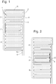
- Fig. 1 is a schematic plan view of an in a conventional manner in a roll-bond method produced evaporator.
- the evaporator plate has a base plate 1 of substantially rectangular shape, wherein over the rectangular basic shape in a right upper corner a narrow edge strip 2 protrudes.
- a throttle line 3 extends parallel to the right edge of the base plate 1 to a connection point 4 on the edge strip. 2
- a running on the base plate 1 in meanders refrigerant line 5 divides the base plate 1 in an upper, a middle and a lower portion 6, 7, 8, by the upper section 6 first in the middle section 7 and then on the detour back over the upper portion 6 extends to the lower portion 8.
- a suction line 9 is connected to a connection point 10 at the lower edge of the base plate 1.
- the middle section 7 is cut free, a section line 11 extending here from the left edge between the sections 7, 8 and at right angles to separate a connecting strip 12 from the central section 7 on which the refrigerant line 5 from the upper portion 6 is rectilinear to the lower portion 8.
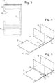
- the middle portion 6 and the upper half of the upper portion 8 are bent at right angles, as in FIGS 3 and 4 to form back panel, floor and ceiling panel segments 13, 14 and 15, respectively, for a freezer compartment evaporator.
- Fig. 6 shows the resulting evaporator assembly installed in a refrigerator.
- the refrigerator shown schematically in section has a known per se structure with a frost compartment 18 in the upper and a normal refrigeration compartment 19 in the lower region of a body 20, a lying between the compartments 18, 19 partition wall 23 and recessed at the bottom of the back of the body 20 niche , which receives a compressor 21 and possibly other parts of the refrigerant circuit of the device.
- a behind the rear wall of the body 20 arranged condenser is designated 22.
- the rear wall plate segment 13 obtained from the upper portion of the original evaporator board fills the rear wall of the frost compartment 13, the plate segments 14, 15 each extend over a major part of its floor or ceiling.
- the bend 16 of the connecting strip 12 the distance between the lower portion 8 and the rear wall plate segment 13 is reduced to the thickness of the partition wall 23 between the compartments 18, 19, so that the lower portion 8 at the rear wall of the normal refrigeration compartment 19 up to whose upper edge extends.
Landscapes
- Engineering & Computer Science (AREA)
- Physics & Mathematics (AREA)
- Mechanical Engineering (AREA)
- Thermal Sciences (AREA)
- General Engineering & Computer Science (AREA)
- Devices That Are Associated With Refrigeration Equipment (AREA)
Description
- Die vorliegende Erfindung betrifft ein Kältegerät mit einer Verdampferanordnung, die einen ersten und einen zweiten Verdampfer umfasst, die auf einteilig zusammenhängenden Plattensegmenten einer im Roll-Bond-Verfahren hergestellten Verdampferplatine ausgebildet sind. Derartige Verdampferanordnungen werden insbesondere in Kältegeräten mit einem Normalkühlfach und einem Frostfach eingesetzt, um in einem einfachen Aufbau beide Fächer zu kühlen.
- Eine ausreichende Kühlung des Normalkühlfachs kann gewährleistet werden, wenn nur ein Teil von dessen Rückwand von einem Verdampfer bedeckt ist. Bei einem Frostfach ist das Verhältnis von erforderlicher Verdampferfläche zum Volumen erheblich größer, so dass es meist nicht reicht, den Verdampfer nur an der Rückwand vorzusehen. Wenn beide Verdampfer aus einer zusammenhängenden Platine geformt werden sollen und der Verdampfer des Frostfachs sich auch über eine Trennwand zwischen Frostfach und Normalkühlfach erstrecken muss, um eine ausreichende Kühlung zu erreichen, ergibt sich das Problem, dass das sich in der Trennwand erstreckende Plattensegment nur aus einer Region der Platine geformt werden kann, die ursprünglich zwischen zwei jeweils Rückwand-Plattensegmente von Normalkühlfach- und Frostfachverdampfer bildenden Bereichen der Platine liegt. Um dennoch eine kompakte Verdampferanordnung zu erhalten, ist es z.B. aus
DE 198 18 288 A1 bekannt, einen Streifen der Verdampferplatine, der die Rückwand-Plattensegmente der zwei Verdampfer verbindet, in eine Wellenform zu biegen, um den Abstand zwischen Normalkühlfach-Verdampfer und FrostfachVerdampfer klein machen zu können. Daher besteht die Gefahr, dass eine an den ersten Verdampfer angeschlossene Drosselleitung beim Biegen des Streifens und Annähern der Plattensegmente aneinander beschädigt wird. Das DokumentUS 2 966 781 A offenbart ein Kältegerät mit einer Verdampferanordnung gemäß dem Oberbegriff des Anspruchs 1. Aufgabe der Erfindung ist daher, ein Kältegerät mit einer Verdampferanordnung, die einen ersten und einen zweiten Verdampfer umfasst, wobei der erste Verdampfer wenigstens zwei an einer Biegelinie einteilig zusammenhängende Plattensegmente umfasst, der zweite Verdampfer ein Plattensegment mit einem der Biegelinie benachbarten, von dem ersten Verdampfer durch einen Spalt getrennten Rand umfasst und die beiden Verdampfer durch einen den Spalt überbrückenden, gewellten Streifen einteilig verbunden sind, anzugeben, der sicher und ohne eine Gefahr der Beschädigung einer entlang des Randes des zweiten Verdampfers verlaufenden und an den ersten Verdampfer angeschlossenen Drosselleitung geformt werden kann. - Die Aufgabe wird dadurch gelöst, dass in der Drosselleitung in Höhe des Spalts ebenfalls s-förmige Wellen geformt sind. Das heißt, während herkömmlicherweise eine Drosselleitung bemessen ist, um den Verdampfer ohne Umwege mit einer anderen Komponente des Kältemittelkreises des Kältegeräts zu verbinden, hat erfindungsgemäß die Drosselleitung eine ausreichende Länge, um, auch wenn sie wie der verbindende Streifen in Wellen gelegt ist, die Verdampferanordnung noch mit den übrigen Komponenten des Kältemittelkreises verbinden zu können. Es ist daher nicht notwendig, die Drosselleitung vor einer Verformung zu schützen, sondern es kann gezielt die gleiche Verformung in die Drosselleitung wie in den verbindenden Streifen eingebracht werden.
- Dies ist am einfachsten möglich, wenn der Verlauf der Drosselleitung in Höhe des Spalts parallel zu dem die Verdampfer verbindenden Streifen ist.
- Wenn die Verdampfer zwischen der Drosselleitung und einer zweiten Kältemittelleitung in Reihe verbunden sind, hat die Drosselleitung vorzugsweise einen kleineren Querschnitt als die zweite, da sie um so leichter zu biegen ist, je kleiner ihr Querschnitt ist.
- Die zweite Kältemittelleitung ist vorzugsweise an den zweiten Verdampfer angeschlossen. So besteht keinerlei Notwendigkeit, in der zweiten Kältemittelleitung Wellen zu formen.
- Weiterhin ist es Aufgabe der Erfindung ein einfaches und kostengünstiges Verfahren zur Herstellung einer Verdampferanordnung anzugeben. Diese Aufgabe wird durch ein Verfahren zum Herstellen der Verdampferanordnung mit den Schritten
- a) Herstellen einer Verdampferplatine im Roll-Bond-Verfahren;
- b) Aufschneiden der Verdampferplatine zwischen dem zweiten Verdampfer und einem ersten Plattensegment des ersten Verdampfers unter Ausbildung eines den zweiten Verdampfer mit einem zweiten Plattensegment des ersten Verdampfers verbindenden Streifens;
- c) Abwinkeln des ersten Plattensegments entlang der Biegelinie;
- d) Formen von Wellen in dem Streifen, um den zweiten Verdampfer und das zweite Plattensegment einander anzunähern; und
- e) Formen von Wellen in einer sich neben dem ersten Verdampfer her zum zweiten Verdampfer erstreckenden Drosselleitung, gelöst.
- Weitere Merkmale und Vorteile der Erfindung ergeben sich aus der nachfolgenden Beschreibung von Ausführungsbeispielen unter Bezugnahme auf die beigefügten Figuren. Es zeigen:
- Fig. 1
- eine schematische Draufsicht auf eine Verdampferplatine, mit der die vorliegende Erfindung ausführbar ist;
- Fig. 2
- eine Draufsicht auf die Verdampferplatine mit frei geschnittenem ersten Plattensegment des ersten Verdampfers;
- Fig. 3
- eine Draufsicht auf die Verdampferplatine mit abgebogenen Plattensegmenten;
- Fig. 4
- eine schematische perspektivische Ansicht der Verdampferplatine mit abgebogenen Plattensegmenten;
- Fig. 5
- eine perspektivische Ansicht der aus der Platine der
Fig. 4 durch Biegen des Verbindungsstreifens und der Drosselleitung erhaltenen Verdampferanordnung; und - Fig. 6
- einen schematischen Schnitt durch ein Kältegerät, in dem die Verdampferanordnung der
Fig. 5 eingebaut ist. -
Fig. 1 ist eine schematische Draufsicht auf eine in an sich bekannter Weise in einem Roll-Bond-Verfahren hergestellte Verdampferplatine. Die Verdampferplatine hat eine Grundplatte 1 von im Wesentlichen rechteckiger Gestalt, wobei über die rechteckige Grundform in einer rechten oberen Ecke ein schmaler Randstreifen 2 übersteht. Eine Drosselleitung 3 erstreckt sich parallel zum rechten Rand der Grundplatte 1 bis zu einer Anschlussstelle 4 auf dem Randstreifen 2. - Eine auf der Grundplatte 1 in Mäandern verlaufende Kältemittelleitung 5 gliedert die Grundplatte 1 in einen oberen, einen mittleren und einen unteren Abschnitt 6, 7, 8, indem sie sich vom oberen Abschnitt 6 zunächst in den mittleren Abschnitt 7 und dann auf dem Umweg zurück über den oberen Abschnitt 6 zum unteren Abschnitt 8 erstreckt. Eine Saugleitung 9 ist an einer Anschlussstelle 10 am unteren Rand der Grundplatte 1 angeschlossen.
- In einem ersten Schritt der Fertigung der erfindungsgemäßen Verdampferanordnung wird der mittlere Abschnitt 7 frei geschnitten, wobei eine Schnittlinie 11 hier sich vom linken Rand aus zwischen den Abschnitten 7, 8 und im rechten Winkel aufwärts erstreckt, um von dem mittleren Abschnitt 7 einen Verbindungsstreifen 12 abzutrennen, auf dem die Kältemittelleitung 5 vom oberen Abschnitt 6 geradlinig zum unteren Abschnitt 8 verläuft.
- Im nächsten Schritt werden der mittlere Abschnitt 6 und die obere Hälfte des oberen Abschnitts 8 rechtwinklig abgebogen, wie in den
Fig. 3 und 4 zu erkennen, um Rückwand-, Boden- und Decken-Plattensegmente 13, 14 bzw. 15 für einen FrostfachVerdampfer zu bilden. - Als nächstes werden der Verbindungsstreifen 12 und die daneben verlaufende Drosselleitung 3 mit Hilfe von in der Perspektive der
Fig. 4 von oben und unten dagegen gedrückten Werkzeugen nach oben und unten ausgelenkt, wodurch eine S-förmige Biegung 16 bzw 17 in dem Verbindungsstreifen 12 und der Drosselleitung 3 geformt wird und der untere Abschnitt 8 nahe an das Rückwandsegment 13 heranrückt. -
Fig. 6 zeigt die so erhaltene Verdampferanordnung eingebaut in einem Kältegerät. Das schematisch im Schnitt gezeigte Kältegerät hat einen an sich bekannten Aufbau mit einem Frostfach 18 im oberen und einem Normalkühlfach 19 im unteren Bereich eines Korpus 20, einer zwischen den Fächern 18, 19 liegenden Trennwand 23 und einer unten an der Rückseite des Korpus 20 ausgesparten Nische, die einen Verdichter 21 und gegebenenfalls andere Teile des Kältemittelkreises des Geräts aufnimmt. Ein hinter der Rückwand des Korpus 20 angeordneter Verflüssiger ist mit 22 bezeichnet. - Das aus dem oberen Abschnitt der ursprünglichen Verdampferplatine erhaltene Rückwand-Plattensegment 13 füllt die Rückwand des Frostfachs 13 aus, die Plattensegmente 14, 15 erstrecken sich jeweils über einen Großteil von dessen Boden bzw. Decke. Durch die Biegung 16 des Verbindungsstreifens 12 ist der Abstand zwischen dem unterem Abschnitt 8 und dem Rückwand-Plattensegment 13 auf die Dicke der Trennwand 23 zwischen den Fächern 18, 19 reduziert, so dass der untere Abschnitt 8 sich an der Rückwand des Normalkühlfachs 19 bis zu deren oberer Kante erstreckt.
Claims (7)
- Kältegerät mit einer Verdampferanordnung, die wenigstens einen ersten (13, 14, 15) und einen zweiten Verdampfer (8) umfasst, die aus einer im Roll-Bond-Verfahren hergestellten Verdampferplatine (1) erhalten sind, wobei der erste Verdampfer (13, 14, 15) wenigstens zwei an einer Biegelinie einteilig zusammenhängende Plattensegmente (13, 14) umfasst, der zweite Verdampfer ein Plattensegment (8) mit einem der Biegelinie benachbarten, von dem ersten Verdampfer (13, 14,15) durch einen Spalt getrennten Rand umfasst und die beiden Verdampfer (8; 13, 14, 15) durch einen den Spalt überbrückenden, gewellten eine S-förmige Biegung (16) aufweisenden Streifen (12) einteilig verbunden sind, dadurch gekennzeichnet, dass eine neben dem Streifen (12) verlaufende Drosselleitung (3) entlang eines Randes des zweiten Verdampfers (8) verläuft, an den ersten Verdampfer (13, 14, 15) angeschlossen ist und in Höhe des Spalts ebenfalls gewellt eine S-förmige Biegung (17) verläuft aufweist.
- Kältegerät nach Anspruch 1, dadurch gekennzeichnet, dass der Verlauf der Drosselleitung (3) in Höhe des Spalts parallel zu dem Materialstreifen (12) ist.
- Kältegerät nach Anspruch 1 oder 2, dadurch gekennzeichnet, dass die Verdampfer (8; 13, 14, 15) zwischen der Drosselleitung (3) und einer zweiten Kältemittelleitung (9) in Reihe verbunden sind und dass die Drosselleitung (3) einen kleineren Querschnitt aufweist als die zweite Kältemittelleitung (9).
- Kältegerät nach Anspruch 3, dadurch gekennzeichnet, dass die zweite Kältemittelleitung (9) an den zweiten Verdampfer (8) angeschlossen ist.
- Kältegerät nach einem der vorhergehenden Ansprüche, dadurch gekennzeichnet, dass eines (14) der Plattensegmente (13, 14, 15) des ersten Verdampfers Teil einer Trennwand (23) zwischen zwei Lagerzonen (18, 19) des Kältegeräts ist.
- Verfahren zum Herstellen einer Verdampferanordnung nach einem der Ansprüche 1 bis 5, mit den Schritten:a) Herstellen einer Verdampferplatine (1) im Roll-Bond-Verfahren;b) Aufschneiden der Verdampferplatine (1) zwischen dem zweiten Verdampfer (8) und einem ersten Plattensegment (14) des ersten Verdampfers (13, 14, 15) unter Ausbildung eines den zweiten Verdampfer (8) mit einem zweiten Plattensegment (13) des ersten Verdampfers (13, 14,1 5) verbindenden Streifens (12);c) Abwinkeln des ersten Plattensegments (14) entlang der Biegelinie;d) Formen von einer s-förmigen Biegung (16) in dem Streifen (12), um den zweiten Verdampfer (8) und das zweite Plattensegment (13) einander anzunähern,gekennzeichnet durch den Schritt:e) Formen einer S-förmigen Biegung (17) in einer sich neben dem ersten Verdampfer (8) her zum zweiten Verdampfer (13, 14, 15) erstreckenden und neben dem Streifen (12) verlaufenden Drosselleitung (3).
- Verfahren nach Anspruch 6, dadurch gekennzeichnet, dass die Biegung (17) der Drosselleitung (3) gleichzeitig mit der Biegung (16) des Streifens (12) geformt wird.
Priority Applications (1)
| Application Number | Priority Date | Filing Date | Title |
|---|---|---|---|
| PL08105261T PL2040015T3 (pl) | 2007-09-18 | 2008-09-08 | Urządzenie chłodnicze z układem parownika i sposób wytwarzania układu parownika |
Applications Claiming Priority (1)
| Application Number | Priority Date | Filing Date | Title |
|---|---|---|---|
| DE102007044392A DE102007044392A1 (de) | 2007-09-18 | 2007-09-18 | Kältegerät mit einer Verdampferanordnung und Herstellungsverfahren für die Verdampferanordnung |
Publications (3)
| Publication Number | Publication Date |
|---|---|
| EP2040015A2 EP2040015A2 (de) | 2009-03-25 |
| EP2040015A3 EP2040015A3 (de) | 2015-03-04 |
| EP2040015B1 true EP2040015B1 (de) | 2018-07-11 |
Family
ID=40242624
Family Applications (1)
| Application Number | Title | Priority Date | Filing Date |
|---|---|---|---|
| EP08105261.5A Not-in-force EP2040015B1 (de) | 2007-09-18 | 2008-09-08 | Kältegerät mit einer Verdampferanordnung und Herstellungsverfahren für die Verdampferanordnung |
Country Status (3)
| Country | Link |
|---|---|
| EP (1) | EP2040015B1 (de) |
| DE (1) | DE102007044392A1 (de) |
| PL (1) | PL2040015T3 (de) |
Families Citing this family (2)
| Publication number | Priority date | Publication date | Assignee | Title |
|---|---|---|---|---|
| CN106556183A (zh) * | 2015-09-27 | 2017-04-05 | 王秀红 | 多面蒸发器管板组件 |
| DE102016208494A1 (de) * | 2016-05-18 | 2017-11-23 | BSH Hausgeräte GmbH | Kältegerät und Verfahren zu dessen Fertigung |
Citations (1)
| Publication number | Priority date | Publication date | Assignee | Title |
|---|---|---|---|---|
| US2966781A (en) * | 1956-03-05 | 1961-01-03 | Philco Corp | Refrigeration apparatus and methods of manufacturing the same |
Family Cites Families (6)
| Publication number | Priority date | Publication date | Assignee | Title |
|---|---|---|---|---|
| DE7431690U (de) * | 1975-07-03 | Bosch Siemens Hausgeraete Gmbh | Verdampfer für Kühlgeräte, Insbesondere Zweitemperaturen-Kühlschränke | |
| US3263440A (en) * | 1964-12-14 | 1966-08-02 | Electrolux Ab | Refrigeration |
| DE9216383U1 (de) * | 1992-12-02 | 1993-01-28 | Bauknecht Hausgeräte GmbH, 7000 Stuttgart | Kühl-Gefrierkombination |
| DE4439996C5 (de) * | 1994-11-09 | 2006-08-10 | BSH Bosch und Siemens Hausgeräte GmbH | Kältegerät |
| IT1296073B1 (it) * | 1997-11-06 | 1999-06-09 | Whirlpool Co | Metodo per ottenere un evaporatore monopezzo per circuiti frigorigeni ed evaporatore ottenuto |
| DE19818288B4 (de) * | 1998-04-23 | 2009-04-30 | BSH Bosch und Siemens Hausgeräte GmbH | Kühlgerät |
-
2007
- 2007-09-18 DE DE102007044392A patent/DE102007044392A1/de not_active Withdrawn
-
2008
- 2008-09-08 PL PL08105261T patent/PL2040015T3/pl unknown
- 2008-09-08 EP EP08105261.5A patent/EP2040015B1/de not_active Not-in-force
Patent Citations (1)
| Publication number | Priority date | Publication date | Assignee | Title |
|---|---|---|---|---|
| US2966781A (en) * | 1956-03-05 | 1961-01-03 | Philco Corp | Refrigeration apparatus and methods of manufacturing the same |
Also Published As
| Publication number | Publication date |
|---|---|
| PL2040015T3 (pl) | 2019-01-31 |
| EP2040015A2 (de) | 2009-03-25 |
| EP2040015A3 (de) | 2015-03-04 |
| DE102007044392A1 (de) | 2009-03-19 |
Similar Documents
| Publication | Publication Date | Title |
|---|---|---|
| EP3129731B1 (de) | Haushaltskältegerät umfassend einen verdichterfüsse aufweisenden verdichter | |
| EP3458784B1 (de) | Kältegerät und verfahren zu dessen fertigung | |
| EP1702190B1 (de) | Wärmetauscher und herstellungsverfahren dafür | |
| EP2721357B1 (de) | Kältegerät mit luftkanal | |
| DE102011006953A1 (de) | Haushaltskältegerät mit über Stege verbundene Verdampferplatten | |
| EP3457056B1 (de) | Türabsteller für ein kältergerät | |
| EP2040015A2 (de) | Kältegerät mit einer Verdampferanordnung und Herstellungsverfahren für die Verdampferanordnung | |
| EP2694889B1 (de) | Haushaltskältegerät mit einem kältemittelkreislaufsystem | |
| WO2003036195A1 (de) | Gleitschiene für einen drahtrohrverdampfer | |
| WO2012160086A2 (de) | Haushaltskältegerät mit einer stirnleiste | |
| WO2018192757A1 (de) | Kältegerät mit an einer innenwand montiertem verdampfer und verfahren zu dessen montage | |
| DE2909704C2 (de) | Verdampfer einer Kälteanlage | |
| EP0795726A1 (de) | Kombinierter Verdampfer für das Sterne- und das Kühlfach eines Haushaltskühlgeräts | |
| DE2936140A1 (de) | Verdampfer einer vorzugsweise kompressorbetriebenen kaelteanlage | |
| EP2392875A2 (de) | Kältegerät mit innen liegendem Verdampfer | |
| WO2011131443A2 (de) | Türblatt, verfahren zum herstellen eines türblatts und kältegerät mit einem türblatt | |
| EP2705313A2 (de) | Wärmeisolierende wand | |
| EP3655714B1 (de) | Kältegerät mit umströmten verdampfer | |
| DE2501364B2 (de) | Kühlschrank | |
| EP4310421A1 (de) | Kältegerät und halter zum fixieren von funktionskomponenten eines kältemittelkreislaufs in einem maschinenraum eines kältegeräts | |
| DE102019216471A1 (de) | Kältegerät mit einem plattenförmigen Isolationselement | |
| DE102019216472A1 (de) | Kältegerät mit einem plattenförmigen Isolationselement | |
| EP1907775B1 (de) | System von kühl- und/oder gefriergeräten | |
| EP1957893A1 (de) | Kältemittel-verflüssiger für ein kältegerät | |
| DE102010003459A1 (de) | Kältegerät, insbesondere Standkältegerät |
Legal Events
| Date | Code | Title | Description |
|---|---|---|---|
| PUAI | Public reference made under article 153(3) epc to a published international application that has entered the european phase |
Free format text: ORIGINAL CODE: 0009012 |
|
| AK | Designated contracting states |
Kind code of ref document: A2 Designated state(s): AT BE BG CH CY CZ DE DK EE ES FI FR GB GR HR HU IE IS IT LI LT LU LV MC MT NL NO PL PT RO SE SI SK TR |
|
| AX | Request for extension of the european patent |
Extension state: AL BA MK RS |
|
| PUAL | Search report despatched |
Free format text: ORIGINAL CODE: 0009013 |
|
| AK | Designated contracting states |
Kind code of ref document: A3 Designated state(s): AT BE BG CH CY CZ DE DK EE ES FI FR GB GR HR HU IE IS IT LI LT LU LV MC MT NL NO PL PT RO SE SI SK TR |
|
| AX | Request for extension of the european patent |
Extension state: AL BA MK RS |
|
| RIC1 | Information provided on ipc code assigned before grant |
Ipc: F25B 39/02 20060101AFI20150127BHEP |
|
| RAP1 | Party data changed (applicant data changed or rights of an application transferred) |
Owner name: BSH HAUSGERAETE GMBH |
|
| 17P | Request for examination filed |
Effective date: 20150904 |
|
| RBV | Designated contracting states (corrected) |
Designated state(s): AT BE BG CH CY CZ DE DK EE ES FI FR GB GR HR HU IE IS IT LI LT LU LV MC MT NL NO PL PT RO SE SI SK TR |
|
| AKX | Designation fees paid |
Designated state(s): AT BE BG CH CY CZ DE DK EE ES FI FR GB GR HR HU IE IS IT LI LT LU LV MC MT NL NO PL PT RO SE SI SK TR |
|
| AXX | Extension fees paid |
Extension state: RS Extension state: AL Extension state: BA Extension state: MK |
|
| 17Q | First examination report despatched |
Effective date: 20161221 |
|
| GRAP | Despatch of communication of intention to grant a patent |
Free format text: ORIGINAL CODE: EPIDOSNIGR1 |
|
| INTG | Intention to grant announced |
Effective date: 20180209 |
|
| GRAS | Grant fee paid |
Free format text: ORIGINAL CODE: EPIDOSNIGR3 |
|
| GRAA | (expected) grant |
Free format text: ORIGINAL CODE: 0009210 |
|
| AK | Designated contracting states |
Kind code of ref document: B1 Designated state(s): AT BE BG CH CY CZ DE DK EE ES FI FR GB GR HR HU IE IS IT LI LT LU LV MC MT NL NO PL PT RO SE SI SK TR |
|
| REG | Reference to a national code |
Ref country code: GB Ref legal event code: FG4D Free format text: NOT ENGLISH |
|
| REG | Reference to a national code |
Ref country code: CH Ref legal event code: EP |
|
| REG | Reference to a national code |
Ref country code: AT Ref legal event code: REF Ref document number: 1017291 Country of ref document: AT Kind code of ref document: T Effective date: 20180715 |
|
| REG | Reference to a national code |
Ref country code: IE Ref legal event code: FG4D Free format text: LANGUAGE OF EP DOCUMENT: GERMAN |
|
| REG | Reference to a national code |
Ref country code: DE Ref legal event code: R096 Ref document number: 502008016172 Country of ref document: DE |
|
| REG | Reference to a national code |
Ref country code: NL Ref legal event code: MP Effective date: 20180711 |
|
| REG | Reference to a national code |
Ref country code: LT Ref legal event code: MG4D |
|
| PG25 | Lapsed in a contracting state [announced via postgrant information from national office to epo] |
Ref country code: NL Free format text: LAPSE BECAUSE OF FAILURE TO SUBMIT A TRANSLATION OF THE DESCRIPTION OR TO PAY THE FEE WITHIN THE PRESCRIBED TIME-LIMIT Effective date: 20180711 |
|
| PG25 | Lapsed in a contracting state [announced via postgrant information from national office to epo] |
Ref country code: BG Free format text: LAPSE BECAUSE OF FAILURE TO SUBMIT A TRANSLATION OF THE DESCRIPTION OR TO PAY THE FEE WITHIN THE PRESCRIBED TIME-LIMIT Effective date: 20181011 Ref country code: LT Free format text: LAPSE BECAUSE OF FAILURE TO SUBMIT A TRANSLATION OF THE DESCRIPTION OR TO PAY THE FEE WITHIN THE PRESCRIBED TIME-LIMIT Effective date: 20180711 Ref country code: GR Free format text: LAPSE BECAUSE OF FAILURE TO SUBMIT A TRANSLATION OF THE DESCRIPTION OR TO PAY THE FEE WITHIN THE PRESCRIBED TIME-LIMIT Effective date: 20181012 Ref country code: NO Free format text: LAPSE BECAUSE OF FAILURE TO SUBMIT A TRANSLATION OF THE DESCRIPTION OR TO PAY THE FEE WITHIN THE PRESCRIBED TIME-LIMIT Effective date: 20181011 Ref country code: IS Free format text: LAPSE BECAUSE OF FAILURE TO SUBMIT A TRANSLATION OF THE DESCRIPTION OR TO PAY THE FEE WITHIN THE PRESCRIBED TIME-LIMIT Effective date: 20181111 Ref country code: SE Free format text: LAPSE BECAUSE OF FAILURE TO SUBMIT A TRANSLATION OF THE DESCRIPTION OR TO PAY THE FEE WITHIN THE PRESCRIBED TIME-LIMIT Effective date: 20180711 Ref country code: FI Free format text: LAPSE BECAUSE OF FAILURE TO SUBMIT A TRANSLATION OF THE DESCRIPTION OR TO PAY THE FEE WITHIN THE PRESCRIBED TIME-LIMIT Effective date: 20180711 |
|
| PG25 | Lapsed in a contracting state [announced via postgrant information from national office to epo] |
Ref country code: ES Free format text: LAPSE BECAUSE OF FAILURE TO SUBMIT A TRANSLATION OF THE DESCRIPTION OR TO PAY THE FEE WITHIN THE PRESCRIBED TIME-LIMIT Effective date: 20180711 Ref country code: HR Free format text: LAPSE BECAUSE OF FAILURE TO SUBMIT A TRANSLATION OF THE DESCRIPTION OR TO PAY THE FEE WITHIN THE PRESCRIBED TIME-LIMIT Effective date: 20180711 Ref country code: LV Free format text: LAPSE BECAUSE OF FAILURE TO SUBMIT A TRANSLATION OF THE DESCRIPTION OR TO PAY THE FEE WITHIN THE PRESCRIBED TIME-LIMIT Effective date: 20180711 |
|
| REG | Reference to a national code |
Ref country code: DE Ref legal event code: R097 Ref document number: 502008016172 Country of ref document: DE |
|
| PG25 | Lapsed in a contracting state [announced via postgrant information from national office to epo] |
Ref country code: MC Free format text: LAPSE BECAUSE OF FAILURE TO SUBMIT A TRANSLATION OF THE DESCRIPTION OR TO PAY THE FEE WITHIN THE PRESCRIBED TIME-LIMIT Effective date: 20180711 Ref country code: EE Free format text: LAPSE BECAUSE OF FAILURE TO SUBMIT A TRANSLATION OF THE DESCRIPTION OR TO PAY THE FEE WITHIN THE PRESCRIBED TIME-LIMIT Effective date: 20180711 Ref country code: RO Free format text: LAPSE BECAUSE OF FAILURE TO SUBMIT A TRANSLATION OF THE DESCRIPTION OR TO PAY THE FEE WITHIN THE PRESCRIBED TIME-LIMIT Effective date: 20180711 Ref country code: CZ Free format text: LAPSE BECAUSE OF FAILURE TO SUBMIT A TRANSLATION OF THE DESCRIPTION OR TO PAY THE FEE WITHIN THE PRESCRIBED TIME-LIMIT Effective date: 20180711 |
|
| REG | Reference to a national code |
Ref country code: CH Ref legal event code: PL |
|
| PLBE | No opposition filed within time limit |
Free format text: ORIGINAL CODE: 0009261 |
|
| STAA | Information on the status of an ep patent application or granted ep patent |
Free format text: STATUS: NO OPPOSITION FILED WITHIN TIME LIMIT |
|
| PG25 | Lapsed in a contracting state [announced via postgrant information from national office to epo] |
Ref country code: SK Free format text: LAPSE BECAUSE OF FAILURE TO SUBMIT A TRANSLATION OF THE DESCRIPTION OR TO PAY THE FEE WITHIN THE PRESCRIBED TIME-LIMIT Effective date: 20180711 Ref country code: DK Free format text: LAPSE BECAUSE OF FAILURE TO SUBMIT A TRANSLATION OF THE DESCRIPTION OR TO PAY THE FEE WITHIN THE PRESCRIBED TIME-LIMIT Effective date: 20180711 |
|
| REG | Reference to a national code |
Ref country code: BE Ref legal event code: MM Effective date: 20180930 |
|
| 26N | No opposition filed |
Effective date: 20190412 |
|
| GBPC | Gb: european patent ceased through non-payment of renewal fee |
Effective date: 20181011 |
|
| REG | Reference to a national code |
Ref country code: IE Ref legal event code: MM4A |
|
| PG25 | Lapsed in a contracting state [announced via postgrant information from national office to epo] |
Ref country code: LU Free format text: LAPSE BECAUSE OF NON-PAYMENT OF DUE FEES Effective date: 20180908 |
|
| PG25 | Lapsed in a contracting state [announced via postgrant information from national office to epo] |
Ref country code: IE Free format text: LAPSE BECAUSE OF NON-PAYMENT OF DUE FEES Effective date: 20180908 |
|
| PG25 | Lapsed in a contracting state [announced via postgrant information from national office to epo] |
Ref country code: CH Free format text: LAPSE BECAUSE OF NON-PAYMENT OF DUE FEES Effective date: 20180930 Ref country code: BE Free format text: LAPSE BECAUSE OF NON-PAYMENT OF DUE FEES Effective date: 20180930 Ref country code: FR Free format text: LAPSE BECAUSE OF NON-PAYMENT OF DUE FEES Effective date: 20180911 Ref country code: LI Free format text: LAPSE BECAUSE OF NON-PAYMENT OF DUE FEES Effective date: 20180930 Ref country code: SI Free format text: LAPSE BECAUSE OF FAILURE TO SUBMIT A TRANSLATION OF THE DESCRIPTION OR TO PAY THE FEE WITHIN THE PRESCRIBED TIME-LIMIT Effective date: 20180711 |
|
| PG25 | Lapsed in a contracting state [announced via postgrant information from national office to epo] |
Ref country code: GB Free format text: LAPSE BECAUSE OF NON-PAYMENT OF DUE FEES Effective date: 20181011 |
|
| REG | Reference to a national code |
Ref country code: AT Ref legal event code: MM01 Ref document number: 1017291 Country of ref document: AT Kind code of ref document: T Effective date: 20180908 |
|
| PG25 | Lapsed in a contracting state [announced via postgrant information from national office to epo] |
Ref country code: AT Free format text: LAPSE BECAUSE OF NON-PAYMENT OF DUE FEES Effective date: 20180908 Ref country code: MT Free format text: LAPSE BECAUSE OF FAILURE TO SUBMIT A TRANSLATION OF THE DESCRIPTION OR TO PAY THE FEE WITHIN THE PRESCRIBED TIME-LIMIT Effective date: 20180711 |
|
| PG25 | Lapsed in a contracting state [announced via postgrant information from national office to epo] |
Ref country code: PT Free format text: LAPSE BECAUSE OF FAILURE TO SUBMIT A TRANSLATION OF THE DESCRIPTION OR TO PAY THE FEE WITHIN THE PRESCRIBED TIME-LIMIT Effective date: 20180711 Ref country code: HU Free format text: LAPSE BECAUSE OF FAILURE TO SUBMIT A TRANSLATION OF THE DESCRIPTION OR TO PAY THE FEE WITHIN THE PRESCRIBED TIME-LIMIT; INVALID AB INITIO Effective date: 20080908 |
|
| PG25 | Lapsed in a contracting state [announced via postgrant information from national office to epo] |
Ref country code: CY Free format text: LAPSE BECAUSE OF FAILURE TO SUBMIT A TRANSLATION OF THE DESCRIPTION OR TO PAY THE FEE WITHIN THE PRESCRIBED TIME-LIMIT Effective date: 20180711 |
|
| PGFP | Annual fee paid to national office [announced via postgrant information from national office to epo] |
Ref country code: TR Payment date: 20200902 Year of fee payment: 13 |
|
| PGFP | Annual fee paid to national office [announced via postgrant information from national office to epo] |
Ref country code: DE Payment date: 20220930 Year of fee payment: 15 |
|
| PGFP | Annual fee paid to national office [announced via postgrant information from national office to epo] |
Ref country code: PL Payment date: 20220831 Year of fee payment: 15 |
|
| PGFP | Annual fee paid to national office [announced via postgrant information from national office to epo] |
Ref country code: IT Payment date: 20220930 Year of fee payment: 15 |
|
| REG | Reference to a national code |
Ref country code: DE Ref legal event code: R084 Ref document number: 502008016172 Country of ref document: DE |
|
| REG | Reference to a national code |
Ref country code: DE Ref legal event code: R119 Ref document number: 502008016172 Country of ref document: DE |
|
| PG25 | Lapsed in a contracting state [announced via postgrant information from national office to epo] |
Ref country code: DE Free format text: LAPSE BECAUSE OF NON-PAYMENT OF DUE FEES Effective date: 20240403 |
|
| PG25 | Lapsed in a contracting state [announced via postgrant information from national office to epo] |
Ref country code: TR Free format text: LAPSE BECAUSE OF NON-PAYMENT OF DUE FEES Effective date: 20210908 |
|
| PG25 | Lapsed in a contracting state [announced via postgrant information from national office to epo] |
Ref country code: PL Free format text: LAPSE BECAUSE OF NON-PAYMENT OF DUE FEES Effective date: 20230908 |
|
| PG25 | Lapsed in a contracting state [announced via postgrant information from national office to epo] |
Ref country code: PL Free format text: LAPSE BECAUSE OF NON-PAYMENT OF DUE FEES Effective date: 20230908 |
|
| PG25 | Lapsed in a contracting state [announced via postgrant information from national office to epo] |
Ref country code: IT Free format text: LAPSE BECAUSE OF NON-PAYMENT OF DUE FEES Effective date: 20230908 |
|
| PG25 | Lapsed in a contracting state [announced via postgrant information from national office to epo] |
Ref country code: IT Free format text: LAPSE BECAUSE OF NON-PAYMENT OF DUE FEES Effective date: 20230908 |