EP2039449A1 - Rotierendes Werkzeug mit zahlreichen Schnittstellen zur Werkzeugbefestigung - Google Patents
Rotierendes Werkzeug mit zahlreichen Schnittstellen zur Werkzeugbefestigung Download PDFInfo
- Publication number
- EP2039449A1 EP2039449A1 EP07117056A EP07117056A EP2039449A1 EP 2039449 A1 EP2039449 A1 EP 2039449A1 EP 07117056 A EP07117056 A EP 07117056A EP 07117056 A EP07117056 A EP 07117056A EP 2039449 A1 EP2039449 A1 EP 2039449A1
- Authority
- EP
- European Patent Office
- Prior art keywords
- rotary tool
- tool according
- output shaft
- cavity
- socket
- Prior art date
- Legal status (The legal status is an assumption and is not a legal conclusion. Google has not performed a legal analysis and makes no representation as to the accuracy of the status listed.)
- Granted
Links
Images


Classifications
-
- B—PERFORMING OPERATIONS; TRANSPORTING
- B23—MACHINE TOOLS; METAL-WORKING NOT OTHERWISE PROVIDED FOR
- B23B—TURNING; BORING
- B23B31/00—Chucks; Expansion mandrels; Adaptations thereof for remote control
- B23B31/02—Chucks
- B23B31/10—Chucks characterised by the retaining or gripping devices or their immediate operating means
- B23B31/107—Retention by laterally-acting detents, e.g. pins, screws, wedges; Retention by loose elements, e.g. balls
- B23B31/1072—Retention by axially or circumferentially oriented cylindrical elements
-
- B—PERFORMING OPERATIONS; TRANSPORTING
- B23—MACHINE TOOLS; METAL-WORKING NOT OTHERWISE PROVIDED FOR
- B23B—TURNING; BORING
- B23B31/00—Chucks; Expansion mandrels; Adaptations thereof for remote control
- B23B31/02—Chucks
- B23B31/10—Chucks characterised by the retaining or gripping devices or their immediate operating means
- B23B31/107—Retention by laterally-acting detents, e.g. pins, screws, wedges; Retention by loose elements, e.g. balls
- B23B31/1079—Retention by spring or wire
-
- B—PERFORMING OPERATIONS; TRANSPORTING
- B25—HAND TOOLS; PORTABLE POWER-DRIVEN TOOLS; MANIPULATORS
- B25B—TOOLS OR BENCH DEVICES NOT OTHERWISE PROVIDED FOR, FOR FASTENING, CONNECTING, DISENGAGING OR HOLDING
- B25B21/00—Portable power-driven screw or nut setting or loosening tools; Attachments for drilling apparatus serving the same purpose
- B25B21/02—Portable power-driven screw or nut setting or loosening tools; Attachments for drilling apparatus serving the same purpose with means for imparting impact to screwdriver blade or nut socket
-
- B—PERFORMING OPERATIONS; TRANSPORTING
- B25—HAND TOOLS; PORTABLE POWER-DRIVEN TOOLS; MANIPULATORS
- B25B—TOOLS OR BENCH DEVICES NOT OTHERWISE PROVIDED FOR, FOR FASTENING, CONNECTING, DISENGAGING OR HOLDING
- B25B23/00—Details of, or accessories for, spanners, wrenches, screwdrivers
- B25B23/0007—Connections or joints between tool parts
- B25B23/0035—Connection means between socket or screwdriver bit and tool
-
- B—PERFORMING OPERATIONS; TRANSPORTING
- B23—MACHINE TOOLS; METAL-WORKING NOT OTHERWISE PROVIDED FOR
- B23B—TURNING; BORING
- B23B2231/00—Details of chucks, toolholder shanks or tool shanks
- B23B2231/02—Features of shanks of tools not relating to the operation performed by the tool
- B23B2231/0216—Overall cross sectional shape of the shank
- B23B2231/0228—Square
-
- B—PERFORMING OPERATIONS; TRANSPORTING
- B23—MACHINE TOOLS; METAL-WORKING NOT OTHERWISE PROVIDED FOR
- B23B—TURNING; BORING
- B23B2231/00—Details of chucks, toolholder shanks or tool shanks
- B23B2231/02—Features of shanks of tools not relating to the operation performed by the tool
- B23B2231/0216—Overall cross sectional shape of the shank
- B23B2231/0232—Hexagonal
-
- B—PERFORMING OPERATIONS; TRANSPORTING
- B23—MACHINE TOOLS; METAL-WORKING NOT OTHERWISE PROVIDED FOR
- B23B—TURNING; BORING
- B23B2231/00—Details of chucks, toolholder shanks or tool shanks
- B23B2231/36—Sealed joints
- B23B2231/365—Sealed joints using O-rings
-
- B—PERFORMING OPERATIONS; TRANSPORTING
- B23—MACHINE TOOLS; METAL-WORKING NOT OTHERWISE PROVIDED FOR
- B23B—TURNING; BORING
- B23B2231/00—Details of chucks, toolholder shanks or tool shanks
- B23B2231/46—Pins
-
- Y—GENERAL TAGGING OF NEW TECHNOLOGICAL DEVELOPMENTS; GENERAL TAGGING OF CROSS-SECTIONAL TECHNOLOGIES SPANNING OVER SEVERAL SECTIONS OF THE IPC; TECHNICAL SUBJECTS COVERED BY FORMER USPC CROSS-REFERENCE ART COLLECTIONS [XRACs] AND DIGESTS
- Y10—TECHNICAL SUBJECTS COVERED BY FORMER USPC
- Y10T—TECHNICAL SUBJECTS COVERED BY FORMER US CLASSIFICATION
- Y10T279/00—Chucks or sockets
- Y10T279/17—Socket type
- Y10T279/17128—Self-grasping
- Y10T279/17171—One-way-clutch type
- Y10T279/17188—Side detent
- Y10T279/17196—Ball or roller
-
- Y—GENERAL TAGGING OF NEW TECHNOLOGICAL DEVELOPMENTS; GENERAL TAGGING OF CROSS-SECTIONAL TECHNOLOGIES SPANNING OVER SEVERAL SECTIONS OF THE IPC; TECHNICAL SUBJECTS COVERED BY FORMER USPC CROSS-REFERENCE ART COLLECTIONS [XRACs] AND DIGESTS
- Y10—TECHNICAL SUBJECTS COVERED BY FORMER USPC
- Y10T—TECHNICAL SUBJECTS COVERED BY FORMER US CLASSIFICATION
- Y10T279/00—Chucks or sockets
- Y10T279/17—Socket type
- Y10T279/17666—Radially reciprocating jaws
- Y10T279/17692—Moving-cam actuator
- Y10T279/17743—Reciprocating cam sleeve
-
- Y—GENERAL TAGGING OF NEW TECHNOLOGICAL DEVELOPMENTS; GENERAL TAGGING OF CROSS-SECTIONAL TECHNOLOGIES SPANNING OVER SEVERAL SECTIONS OF THE IPC; TECHNICAL SUBJECTS COVERED BY FORMER USPC CROSS-REFERENCE ART COLLECTIONS [XRACs] AND DIGESTS
- Y10—TECHNICAL SUBJECTS COVERED BY FORMER USPC
- Y10T—TECHNICAL SUBJECTS COVERED BY FORMER US CLASSIFICATION
- Y10T279/00—Chucks or sockets
- Y10T279/17—Socket type
- Y10T279/17761—Side detent
- Y10T279/17786—Spring
-
- Y—GENERAL TAGGING OF NEW TECHNOLOGICAL DEVELOPMENTS; GENERAL TAGGING OF CROSS-SECTIONAL TECHNOLOGIES SPANNING OVER SEVERAL SECTIONS OF THE IPC; TECHNICAL SUBJECTS COVERED BY FORMER USPC CROSS-REFERENCE ART COLLECTIONS [XRACs] AND DIGESTS
- Y10—TECHNICAL SUBJECTS COVERED BY FORMER USPC
- Y10T—TECHNICAL SUBJECTS COVERED BY FORMER US CLASSIFICATION
- Y10T279/00—Chucks or sockets
- Y10T279/29—More than one set of gripping means
Definitions
- the present invention relates to rotary tools and in particular to interfaces for attaching different sorts of working members, such as driver bits or sockets, to the shaft of a rotary tool.
- JP Patent Application No. 10-155574 discloses a hybrid interface that allows one to secure either a driver bit or a socket to rotary tool output shaft.
- the output shaft is configured to include a hexagonal cavity for receiving a driver bit along with means, such as a ball and sleeve arrangement, for attaching or releasing the bit.
- the distal end of the output shaft has a square-shaped periphery, and so it is also able to accommodate a typical socket.
- One embodiment is configured to cooperate with a pin and an O-ring to secure sockets according to a standard used in Japanese markets.
- a second embodiment employs a spring-loaded protrusion mounted to a hole on the periphery of the output shaft to secure sockets configured with an inner annular groove which is typical of the standard used in North American and European markets.
- JP Patent Application No. 2004-190714 discloses a socket attachment interface intended to simplify the attachment of sockets according to the Japanese standard.
- a detachable spring member is secured with a screw to the end face of the output shaft of a rotary tool and includes one or more protrusions that cooperate with one or more through-holes in the socket.
- the present invention provides a hybrid tool attachment interface that incorporates advantages from both of the above-described designs and which can accommodate a driver bit as well as a variety of sockets.
- the design is simple to manufacture and assemble and does not require additional tools for mounting or removing bits or sockets.
- the inventive rotary tool comprises an output shaft having an axis of rotation, a distal neck portion which has at least three neck faces that do not interest the axis of rotation and a generally U-shaped spring element having a base portion and two leg portions, wherein the spring element straddles the distal neck portion.
- the U-shaped spring element is securely attached to the output shaft without any separate fastening means and has the advantage that features that can be used to secure multiple types of working members can be embodied in an inexpensively constructed part that is furthermore easily detachable should it be subject to wear or damage and need to be replaced.
- the design has the advantage that the output shaft is provided with an elongate cavity coaxial with its axis of rotation, so that it can optionally receive a driver bit, thereby providing additional functionality for the user, who can select from either a driver bit or a socket without needing to use a separate adaptor.
- the output shaft is further provided with means for securing a driver bit within the elongate cavity.
- these means comprise a slidably-mounted sleeve which is biased by a spring and which cooperates with balls which act as locking members when a driver bit with a circumferential groove is inserted. In this way, the user can easily remove or attach a driver bit of this type without any separate tools.
- the spring element of the inventive rotary tool has two tip portions, each of which is contiguous with one of the two leg portions. These two tip portions together with the base portion and the two leg portions embrace the distal neck portion to retain the spring element. Hence the force of the spring and its geometry allow the spring plate to surround and fasten itself to the neck region of the output shaft without the need for separate fastening means. Since it is detachable, the user may optionally remove the spring element for replacement or use with certain tool types.
- Each of the two leg portions contacts one of the neck faces of the distal neck portion and this serves to grip around the output shaft to retain the spring element.
- the leg portions contact the neck faces within recessed regions of the neck faces. This has the advantage that the spring plate can lie flush with the rest of the distal neck portion to provide an overall generally flat profile for insertion of a socket.
- Adjoining the recessed faces of the distal neck portion are elevated portions that serve as stop surfaces. These stop surfaces provide the advantage that the spring plate is prohibited from moving axially along the axis of rotation when a socket is inserted onto or removed from the distal neck portion.
- One of the means by which the spring plate retains a socket is by having at least one spring-elastic protrusion on a leg portion. Preferably two such protrusions are present on two leg portions.
- the protrusions can advantageously mate with either an internal groove or a radial cavity within a socket.
- the base portion of the spring element is provided with an opening.
- the opening is positioned generally coaxially with the cavity in the output shaft so they may cooperate to form an insertion pathway for the pin that is used to secure the socket.
- the inventive rotary tool can securely attach working members via at least three different means.
- a driver bit can be inserted and retained in the elongate cavity.
- a socket with an internal groove can be retained via the spring-elastic protrusions.
- a socket with a radial cavity can be retained not only via the spring-elastic protrusions, but also via cooperation with a pin which traverses an opening in the spring plate and a cavity in the output shaft, so that it can be secured by an O-ring extending around the perimeter of the socket.
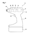
- FIG. 1 An example of a rotary tool according to the present invention is illustrated in Fig. 1 . While the illustrated embodiment is a power tool, and specifically a cordless impact driver, the invention may be advantageously used with a variety of rotary tools irrespective of whether they are powered or whether they include an impact driving function.
- a motor 14 and its associated motor shaft 16 Within housing 10 of rotary power tool 12 are a motor 14 and its associated motor shaft 16.
- a transmission 18 converts the rotation of the motor shaft 16 into increased output torque, but correspondingly reduced speed rotation of the driveshaft 20.
- the driveshaft 20 is coupled to a hammer 22 which is in turn coupled to an output shaft 24.
- the driveshaft 20, hammer 22 and output shaft 24 are configured to transmit repetitive bursts of output torque via a hammer and anvil arrangement as is well known to those skilled in the art.
- US 2006/0237205-A1 An example of such an impact driver is shown in US 2006/0237205-A1 , which is hereby incorporated by reference.
- the tool is provided with a handle 26 and a trigger 28 so that it may be conveniently operated by a user.
- the power source is a DC battery 30 in this exemplary cordless tool, but an AC power source is a standard alternative.
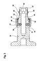
- Figures 2-4 show various views of a tool attachment interface for a rotary tool.
- the output shaft 24 has a proximal neck portion 32, a distal neck portion 34, an end face 36, and an axis of rotation 38.
- An elongate cavity 40 in the output shaft 24 is centered around the axis of rotation 38.
- the cavity is preferably polygonally shaped so that it can accommodate a complementary polygonally-shaped driver bit (not shown).
- a sleeve 44, a compression spring 46, and a retaining ring 48 are mounted around the proximal neck portion 32 of the output shaft 24. All of these elements are secured to the proximal neck portion 32 once a C-ring 50 is inserted into annular groove 52.
- the force from the spring 46 positions the sleeve 44 such that balls 54 mounted in radial cavities 56 are urged partially into the elongate cavity 40 to act as locking members to act on a hexagonal driver bit with an annular groove (e.g., according to the DIN 3126-E6.3 standard) so that it can be securely attached and released from the output shaft 24.
- the radial cavities 56 are sized with a variable diameter, such that the balls 54 may travel within the radial cavities 56 but can only protrude partially into elongate cavity 40. A user can urge the sleeve 44 against the spring force, so that the balls have space enough to exit entirely from the elongate cavity 40. Rather than ball pairs 54, a single ball, an elongate pin, or a blade may alternatively be used as locking members.
- the output shaft 24 is configured with an elongate cavity 40, and the means for securing the driver bit are located within or around the proximal neck portion 32 of the output shaft 24.
- the means for securing the driver bit are located within or around the proximal neck portion 32 of the output shaft 24.
- one or more screws mounted perpendicular to the axis of rotation could also be used to secure the driver bit.
- a magnetic part incorporated into the proximal neck portion 32 could be used to attract and retain the driver bit.
- the sleeve 44 could instead of being biased by the spring 46, the sleeve 44 could instead be threaded to the proximal neck portion 32, so that its position is adjusted via rotation in order to correspondingly position the one or more locking members.
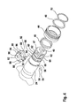
- the distal neck portion 34 of the output shaft 24 is preferably square-shaped in a cross-section taken perpendicular to the axis of rotation 38.
- Detailed features of the distal neck portion 34 are shown in Fig. 4 and 5 .
- Each of its four neck faces 60 is configured with a neck cavity 62 that traverses the space between the neck face 60 and the elongate cavity 40 and comprises a cylindrical portion 64 and a conical portion 66.
- the surface of each neck face 60 is partially recessed.
- Each of four recessed faces 70 are linked by similarly recessed bevel faces 69 at the four corners of the distal neck portion 34.
- Front 67 and rear 68 elevated portions are found on either side of the recessed faces 70 and bevel faces 69.
- the distal neck portion 34 is sufficient to permit a user to mount and secure a Japanese-type socket 71 to the output shaft 24 using a metal pin 72 and a rubber O-ring 74 as retaining means as is customary for this standard (see Fig. 6 ).
- a socket 71 is mounted onto the output shaft 24 such that each inner face 76 of the socket makes contact with elevated portions 68 of each neck face 60.
- a pin 72 is inserted through radial cavities 78 in the socket and through two neck cavities 62 of the output shaft 24.
- an O-ring 74 is mounted around an annular groove 80 of the socket 71 to trap the pin 72.
- a given socket 71 can be mounted in any of four possible orientations relative to the output shaft 24, resulting in the mounting pin 72 traversing the socket 71 in one of two possible orientations. In every case, there is no interference from the driver bit mounting means and therefore the two distinct mounting interfaces may coexist on the same output shaft 24.
- a spring plate 82 comprising a base portion 84, two leg portions 86, two corner portions 88, and two leg tip portions 89 is preferably mounted to the distal neck portion 34 of the output shaft 24.
- Each of the two corner portions 88 link the base portion 84 with a leg portion 86.
- Each of the two leg tip portions 89 extend from the end of the leg portion, that is, they extend from the part of the leg portion 86 opposite the part of the leg portion 86 that interfaces with the base portion 84.
- the spring plate 82 is best visualized in the exploded view of Fig. 4 . It is fastened to the output shaft 24 without any separate fastening means and does not require the use of tools for attaching or detaching.
- the cross section of the mounted spring plate 82 taken perpendicular to the axis of rotation 38 (not shown) is substantially U-shaped, as defined by the base portion 84 and the two leg portions 86.
- the thickness of the spring plate 82 corresponds very closely to the dimensions of the distal neck portion 34, so that when the spring plate 82 is mounted, each of its portions contacts a recessed face 70 or a bevel face 69, so that it is substantially but not necessarily exactly flush with the surface of the front 67 and rear 68 elevated portions of each neck face 60 (see Fig. 5 ). These elevated portions 67, 68 provide a stop surface to counter the axial force acting on the spring plate 82 when a socket is inserted or removed.
- the two corner portions 88 and the two leg tip portions 89 of the spring plate 82 are complementary to the bevel faces 69 of the distal neck portion 34.
- the spring plate 82 can be mounted in any of four possible orientations.
- the spring plate 82 exerts a spring force which tends to grip the distal neck portion 34 via its two leg tip portions 69. It can be manually removed by overcoming this spring force.
- the distal neck portion 34 may alternatively have an asymmetrical design, for example with only two neck cavities 62. In this case, the spring plate 82 is preferably inserted in particular orientations.
- the spring force itself comprises sufficient attachment means for retaining the spring plate 82
- alternatives are possible. If the spring plate 82 were provided with an opening on one of its faces that corresponded to a cavity on the distal neck portion 34, the parts could be secured with a screw or the like.
- a suitable screw head would be flat and its head preferably somewhat recessed within the spring plate 82 so as not to interfere with the insertion of a socket. In addition, such a screw should not be long enough to enter the elongate cavity 40 so as to interfere with the mounting of a driver bit.
- each leg portion 86 of the spring plate 82 there is a spring-elastic protrusion 90.
- Four openings 92 surround the protrusion, thereby establishing four flexible arms 94.
- these openings 92 and arms 94 reduce the force necessary to deflect a protrusion 90 below the surface of the leg portion 86. As will be seen below, this may potentially happen during the insertion of a socket onto the attachment interface. Therefore, a leg portion 86 with two, three, five, six or even more openings can be used towards this same goal and present reasonable alternatives.
- the spring plate 82 is preferably manufactured through stamping of sheet metal and these openings 92 and arms 94 can be readily introduced during this process.
- each protrusion 90 When it is deflected, each protrusion 90 exerts a radial force generally perpendicular to the axis of rotation 38.
- a socket 71 When a socket 71 is inserted, its inner face 76 deflects each protrusion 90 while the socket 71 slides into its mounting position, at which time the protrusion 90 acts on a cavity 78 or groove 100 in the socket 71.
- the spring plate 82 is mounted to the output shaft 24, the position of each protrusion 90 and flexible arm 94 corresponds roughly to the position of the cylindrical portion 64 and conical portion 66 of the neck cavity 62 respectively. This structure provides sufficient space for the protrusion 90 and flexible arms 94 to be deflected in the general direction of the axis of rotation 38 against its inherent spring force.
- the base portion 84 of the spring plate 82 has an opening 96 roughly comparable in diameter to that of the cylindrical portion 64 of a neck cavity 62. Since the opening 96 is positioned coaxially with the neck cavity, a pin 72 can be inserted through these features so that a socket 71 can be mounted using a pin 72 and O-ring 74 even when the spring plate 82 is mounted to the output shaft 24. In this configuration, the inner faces 76 of the socket 71 constantly deflect the protrusions 90, but this is permissible since there is adequate space in the neck cavity 92 to accommodate the protrusions 90 as described above.
- the same socket 71 could be removed, rotated ninety degrees, and inserted past the spring force of the protrusions 90, so that each protrusion 90 engages with a radial cavity 78 in the socket 71 as shown in Fig. 7 .
- a socket 98 with an internal annular groove 100 is also retained by this attachment interface as shown in Fig. 8 .
Priority Applications (3)
| Application Number | Priority Date | Filing Date | Title |
|---|---|---|---|
| EP07117056A EP2039449B1 (de) | 2007-09-24 | 2007-09-24 | Rotierendes Werkzeug mit zahlreichen Schnittstellen zur Werkzeugbefestigung |
| DE602007008424T DE602007008424D1 (de) | 2007-09-24 | 2007-09-24 | Rotierendes Werkzeug mit zahlreichen Schnittstellen zur Werkzeugbefestigung |
| US12/236,034 US8366122B2 (en) | 2007-09-24 | 2008-09-23 | Rotary tool with multiple tool attachment interfaces |
Applications Claiming Priority (1)
| Application Number | Priority Date | Filing Date | Title |
|---|---|---|---|
| EP07117056A EP2039449B1 (de) | 2007-09-24 | 2007-09-24 | Rotierendes Werkzeug mit zahlreichen Schnittstellen zur Werkzeugbefestigung |
Publications (2)
| Publication Number | Publication Date |
|---|---|
| EP2039449A1 true EP2039449A1 (de) | 2009-03-25 |
| EP2039449B1 EP2039449B1 (de) | 2010-08-11 |
Family
ID=39183032
Family Applications (1)
| Application Number | Title | Priority Date | Filing Date |
|---|---|---|---|
| EP07117056A Active EP2039449B1 (de) | 2007-09-24 | 2007-09-24 | Rotierendes Werkzeug mit zahlreichen Schnittstellen zur Werkzeugbefestigung |
Country Status (3)
| Country | Link |
|---|---|
| US (1) | US8366122B2 (de) |
| EP (1) | EP2039449B1 (de) |
| DE (1) | DE602007008424D1 (de) |
Cited By (12)
| Publication number | Priority date | Publication date | Assignee | Title |
|---|---|---|---|---|
| DE102010002350A1 (de) | 2010-02-25 | 2011-08-25 | Robert Bosch GmbH, 70469 | Handwerkzeugmaschine |
| DE102010002352A1 (de) | 2010-02-25 | 2011-08-25 | Robert Bosch GmbH, 70469 | Handwerkzeugmaschine |
| DE102010002353A1 (de) | 2010-02-25 | 2011-08-25 | Robert Bosch GmbH, 70469 | Handwerkzeugmaschine |
| WO2011154230A1 (de) | 2010-06-09 | 2011-12-15 | Robert Bosch Gmbh | Handwerkzeugmaschine mit einer werkzeugaufnahme |
| CN102380857A (zh) * | 2010-09-02 | 2012-03-21 | 罗伯特·博世有限公司 | 电动手工工具机的接合器装置、附件以及电动手工工具机 |
| DE202011107082U1 (de) | 2011-10-24 | 2012-04-03 | Robert Bosch Gmbh | Handwerkzeugmaschine |
| DE102012207332A1 (de) | 2012-05-03 | 2013-11-07 | Robert Bosch Gmbh | Handwerkzeugmaschine |
| CN104742072A (zh) * | 2013-12-26 | 2015-07-01 | 南京德朔实业有限公司 | 电动螺丝批 |
| FR3030326A1 (fr) * | 2014-12-22 | 2016-06-24 | Renault Sa | Organe d'interface, organe d'extension pour dispositif d'entrainement portatif et dispositif d'entrainement portatif correspondant |
| EP3168005A1 (de) * | 2015-08-03 | 2017-05-17 | Chervon (HK) Limited | Drehmomentabgabewerkzeug und drehmomentausgabeanordnung |
| JP2017087334A (ja) * | 2015-11-09 | 2017-05-25 | 株式会社 ムラテクノロジー | 基軸ホルダ及び電動工具 |
| CN109605262A (zh) * | 2017-09-21 | 2019-04-12 | 薪萤企业有限公司 | 套筒 |
Families Citing this family (6)
| Publication number | Priority date | Publication date | Assignee | Title |
|---|---|---|---|---|
| JP5802138B2 (ja) * | 2012-01-19 | 2015-10-28 | Tone株式会社 | ソケット及びこれを装着した動力工具 |
| JP2018144175A (ja) * | 2017-03-06 | 2018-09-20 | 株式会社プロス | インパクトレンチ用取付具またはインパクトレンチ用ソケット |
| US11285589B2 (en) | 2017-11-21 | 2022-03-29 | SHIN YING ENTPR Co., Ltd. | Socket |
| US20190152029A1 (en) * | 2017-11-21 | 2019-05-23 | SHIN YING ENTPR Co., Ltd. | Socket |
| JP2021194737A (ja) * | 2020-06-12 | 2021-12-27 | 株式会社イチネンMtm | 脱落防止具 |
| DE102022100891A1 (de) | 2022-01-17 | 2023-07-20 | Wera Werkzeuge Gmbh | Schraubwerkzeug für Nüsse und Bits |
Citations (7)
| Publication number | Priority date | Publication date | Assignee | Title |
|---|---|---|---|---|
| US5398946A (en) * | 1993-12-29 | 1995-03-21 | Poly-Tech Industries | Chuck having one-step lock and release |
| US5481949A (en) | 1994-08-15 | 1996-01-09 | Yen; En-Ji | Locking member for use in hand tools |
| JPH10155574A (ja) | 1996-11-27 | 1998-06-16 | Sanyo Electric Co Ltd | 昇降式カウンタートップ装置及びキッチン装置 |
| US5974919A (en) * | 1994-09-06 | 1999-11-02 | Robert Bosch Gmbh | Screwing device for ultrasound-controlled tightening of screw connections |
| JP2004190714A (ja) | 2002-12-09 | 2004-07-08 | Sakae Riken Kogyo Co Ltd | シフトレバー誤操作防止装置 |
| US20050132846A1 (en) * | 2003-12-18 | 2005-06-23 | Yeong-Fa Lai | Driving shaft for a ratchet spanner |
| JP2006007389A (ja) * | 2004-06-29 | 2006-01-12 | Hitachi Koki Co Ltd | インパクト工具 |
Family Cites Families (7)
| Publication number | Priority date | Publication date | Assignee | Title |
|---|---|---|---|---|
| US2805594A (en) * | 1955-02-10 | 1957-09-10 | Fogel Aaron | Nut-holding socket wrench |
| US3549160A (en) * | 1968-12-04 | 1970-12-22 | Skil Corp | Socket retention assembly |
| US4477096A (en) * | 1982-08-02 | 1984-10-16 | Chicago Pneumatic Tool Company | Socket retainer |
| US5309798A (en) * | 1993-03-17 | 1994-05-10 | Inno-Ware Enterprises Limited | Tool bit retaining assembly |
| US6325393B1 (en) * | 1999-10-01 | 2001-12-04 | Tsai-Ching Chen | Chuck device for tools |
| US20060237205A1 (en) | 2005-04-21 | 2006-10-26 | Eastway Fair Company Limited | Mode selector mechanism for an impact driver |
| DE102007056637A1 (de) * | 2007-11-24 | 2009-05-28 | GM Global Technology Operations, Inc., Detroit | Kombinationsschraubernuss |
-
2007
- 2007-09-24 DE DE602007008424T patent/DE602007008424D1/de active Active
- 2007-09-24 EP EP07117056A patent/EP2039449B1/de active Active
-
2008
- 2008-09-23 US US12/236,034 patent/US8366122B2/en active Active
Patent Citations (7)
| Publication number | Priority date | Publication date | Assignee | Title |
|---|---|---|---|---|
| US5398946A (en) * | 1993-12-29 | 1995-03-21 | Poly-Tech Industries | Chuck having one-step lock and release |
| US5481949A (en) | 1994-08-15 | 1996-01-09 | Yen; En-Ji | Locking member for use in hand tools |
| US5974919A (en) * | 1994-09-06 | 1999-11-02 | Robert Bosch Gmbh | Screwing device for ultrasound-controlled tightening of screw connections |
| JPH10155574A (ja) | 1996-11-27 | 1998-06-16 | Sanyo Electric Co Ltd | 昇降式カウンタートップ装置及びキッチン装置 |
| JP2004190714A (ja) | 2002-12-09 | 2004-07-08 | Sakae Riken Kogyo Co Ltd | シフトレバー誤操作防止装置 |
| US20050132846A1 (en) * | 2003-12-18 | 2005-06-23 | Yeong-Fa Lai | Driving shaft for a ratchet spanner |
| JP2006007389A (ja) * | 2004-06-29 | 2006-01-12 | Hitachi Koki Co Ltd | インパクト工具 |
Cited By (22)
| Publication number | Priority date | Publication date | Assignee | Title |
|---|---|---|---|---|
| CN102762327A (zh) * | 2010-02-25 | 2012-10-31 | 罗伯特·博世有限公司 | 手持式工具机 |
| DE102010002352A1 (de) | 2010-02-25 | 2011-08-25 | Robert Bosch GmbH, 70469 | Handwerkzeugmaschine |
| DE102010002353A1 (de) | 2010-02-25 | 2011-08-25 | Robert Bosch GmbH, 70469 | Handwerkzeugmaschine |
| WO2011104105A1 (de) | 2010-02-25 | 2011-09-01 | Robert Bosch Gmbh | Handwerkzeugmaschine |
| WO2011104109A1 (de) | 2010-02-25 | 2011-09-01 | Robert Bosch Gmbh | Handwerkzeugmaschine |
| DE102010002350A1 (de) | 2010-02-25 | 2011-08-25 | Robert Bosch GmbH, 70469 | Handwerkzeugmaschine |
| DE102010002352B4 (de) * | 2010-02-25 | 2021-03-18 | Robert Bosch Gmbh | Handwerkzeugmaschine |
| CN102762327B (zh) * | 2010-02-25 | 2016-07-06 | 罗伯特·博世有限公司 | 手持式工具机 |
| WO2011154230A1 (de) | 2010-06-09 | 2011-12-15 | Robert Bosch Gmbh | Handwerkzeugmaschine mit einer werkzeugaufnahme |
| DE102010030642A1 (de) | 2010-06-09 | 2011-12-15 | Robert Bosch Gmbh | Handwerkzeugmaschine mit einer Werkzeugaufnahme |
| US9718173B2 (en) | 2010-06-09 | 2017-08-01 | Robert Bosch Gmbh | Handheld machine tool having a tool holding fixture |
| CN102380857A (zh) * | 2010-09-02 | 2012-03-21 | 罗伯特·博世有限公司 | 电动手工工具机的接合器装置、附件以及电动手工工具机 |
| US9566696B2 (en) | 2011-10-24 | 2017-02-14 | Robert Bosch Gmbh | Handheld machine tool |
| WO2013060545A1 (de) | 2011-10-24 | 2013-05-02 | Robert Bosch Gmbh | Handwerkzeugmaschine |
| DE202011107082U1 (de) | 2011-10-24 | 2012-04-03 | Robert Bosch Gmbh | Handwerkzeugmaschine |
| DE102012207332A1 (de) | 2012-05-03 | 2013-11-07 | Robert Bosch Gmbh | Handwerkzeugmaschine |
| CN104742072A (zh) * | 2013-12-26 | 2015-07-01 | 南京德朔实业有限公司 | 电动螺丝批 |
| CN104742074A (zh) * | 2013-12-26 | 2015-07-01 | 南京德朔实业有限公司 | 电动螺丝批 |
| FR3030326A1 (fr) * | 2014-12-22 | 2016-06-24 | Renault Sa | Organe d'interface, organe d'extension pour dispositif d'entrainement portatif et dispositif d'entrainement portatif correspondant |
| EP3168005A1 (de) * | 2015-08-03 | 2017-05-17 | Chervon (HK) Limited | Drehmomentabgabewerkzeug und drehmomentausgabeanordnung |
| JP2017087334A (ja) * | 2015-11-09 | 2017-05-25 | 株式会社 ムラテクノロジー | 基軸ホルダ及び電動工具 |
| CN109605262A (zh) * | 2017-09-21 | 2019-04-12 | 薪萤企业有限公司 | 套筒 |
Also Published As
| Publication number | Publication date |
|---|---|
| US20090079143A1 (en) | 2009-03-26 |
| EP2039449B1 (de) | 2010-08-11 |
| DE602007008424D1 (de) | 2010-09-23 |
| US8366122B2 (en) | 2013-02-05 |
Similar Documents
| Publication | Publication Date | Title |
|---|---|---|
| EP2039449B1 (de) | Rotierendes Werkzeug mit zahlreichen Schnittstellen zur Werkzeugbefestigung | |
| JP4988105B2 (ja) | ホールソー及びパイロットドリルビットと共に使用するための迅速交換マンドレルアセンブリ | |
| CA2725713C (en) | Irregular-shank tools and drivers therefor | |
| US8132990B2 (en) | Bit holding apparatus for use with a power tool | |
| US7374377B2 (en) | Bit holding apparatus for use with a power tool | |
| US6164169A (en) | Socket mounting arrangement | |
| US8220135B2 (en) | Compound tool with screwdriver attachment | |
| EP0685300A1 (de) | Umkehrbares Bohrantriebswerkzeug | |
| CA2328446A1 (en) | Quick coupler mechanism for power tool bits | |
| EP1502706A1 (de) | Schraubendrehereinsatz zum halten von schrauben und dessen kombination mit schrauben | |
| US20230101161A1 (en) | Modular tool bit holder system | |
| US6766716B1 (en) | Adapter for a ratchet wrench for engaging with socket or other tools of the like | |
| US7083003B1 (en) | Power tool with detachable drive end | |
| US5343786A (en) | Bit and socket combination | |
| US20030085534A1 (en) | Quick attachment release system for a rotary hand tool | |
| EP2042270B1 (de) | Drehwerkzeug | |
| CN215240537U (zh) | 工具接杆 | |
| US7201087B2 (en) | Multi-functional tool head | |
| CN113276050B (zh) | 工具接杆 | |
| CA2573827C (en) | Socket wrench/adaptor combination | |
| JP2010221336A (ja) | 複数の工具取付けインターフェースを備えた回転工具 | |
| CN108068066B (zh) | 转换夹头、与其配合使用的工具主体及配合使用方法 | |
| US20020185286A1 (en) | Impact tool with detachable drive end | |
| CN213053050U (zh) | 一种锯条快换结构 | |
| CA3098777A1 (en) | Rotary tool, rotary tool adapter and rotary tool bit drive shaft |
Legal Events
| Date | Code | Title | Description |
|---|---|---|---|
| PUAI | Public reference made under article 153(3) epc to a published international application that has entered the european phase |
Free format text: ORIGINAL CODE: 0009012 |
|
| AK | Designated contracting states |
Kind code of ref document: A1 Designated state(s): AT BE BG CH CY CZ DE DK EE ES FI FR GB GR HU IE IS IT LI LT LU LV MC MT NL PL PT RO SE SI SK TR |
|
| AX | Request for extension of the european patent |
Extension state: AL BA HR MK RS |
|
| 17P | Request for examination filed |
Effective date: 20090925 |
|
| 17Q | First examination report despatched |
Effective date: 20091019 |
|
| AKX | Designation fees paid |
Designated state(s): DE GB |
|
| GRAP | Despatch of communication of intention to grant a patent |
Free format text: ORIGINAL CODE: EPIDOSNIGR1 |
|
| GRAC | Information related to communication of intention to grant a patent modified |
Free format text: ORIGINAL CODE: EPIDOSCIGR1 |
|
| GRAS | Grant fee paid |
Free format text: ORIGINAL CODE: EPIDOSNIGR3 |
|
| GRAA | (expected) grant |
Free format text: ORIGINAL CODE: 0009210 |
|
| AK | Designated contracting states |
Kind code of ref document: B1 Designated state(s): DE GB |
|
| REG | Reference to a national code |
Ref country code: GB Ref legal event code: FG4D |
|
| REF | Corresponds to: |
Ref document number: 602007008424 Country of ref document: DE Date of ref document: 20100923 Kind code of ref document: P |
|
| PLBE | No opposition filed within time limit |
Free format text: ORIGINAL CODE: 0009261 |
|
| STAA | Information on the status of an ep patent application or granted ep patent |
Free format text: STATUS: NO OPPOSITION FILED WITHIN TIME LIMIT |
|
| 26N | No opposition filed |
Effective date: 20110512 |
|
| REG | Reference to a national code |
Ref country code: DE Ref legal event code: R097 Ref document number: 602007008424 Country of ref document: DE Effective date: 20110512 |
|
| PGFP | Annual fee paid to national office [announced via postgrant information from national office to epo] |
Ref country code: GB Payment date: 20120920 Year of fee payment: 6 |
|
| GBPC | Gb: european patent ceased through non-payment of renewal fee |
Effective date: 20130924 |
|
| PG25 | Lapsed in a contracting state [announced via postgrant information from national office to epo] |
Ref country code: GB Free format text: LAPSE BECAUSE OF NON-PAYMENT OF DUE FEES Effective date: 20130924 |
|
| PGFP | Annual fee paid to national office [announced via postgrant information from national office to epo] |
Ref country code: DE Payment date: 20221125 Year of fee payment: 16 |