EP2035314B1 - Plate-forme de levage et procédé de montage d'une plate-forme de levage - Google Patents
Plate-forme de levage et procédé de montage d'une plate-forme de levage Download PDFInfo
- Publication number
- EP2035314B1 EP2035314B1 EP07730243A EP07730243A EP2035314B1 EP 2035314 B1 EP2035314 B1 EP 2035314B1 EP 07730243 A EP07730243 A EP 07730243A EP 07730243 A EP07730243 A EP 07730243A EP 2035314 B1 EP2035314 B1 EP 2035314B1
- Authority
- EP
- European Patent Office
- Prior art keywords
- profile
- base
- lifting platform
- lifting
- console
- Prior art date
- Legal status (The legal status is an assumption and is not a legal conclusion. Google has not performed a legal analysis and makes no representation as to the accuracy of the status listed.)
- Active
Links
Images


Classifications
-
- B—PERFORMING OPERATIONS; TRANSPORTING
- B66—HOISTING; LIFTING; HAULING
- B66B—ELEVATORS; ESCALATORS OR MOVING WALKWAYS
- B66B9/00—Kinds or types of lifts in, or associated with, buildings or other structures
- B66B9/16—Mobile or transportable lifts specially adapted to be shifted from one part of a building or other structure to another part or to another building or structure
Definitions
- the invention relates to a lifting platform and a method for building a lifting platform.
- Siemensische In the field of construction so-called Wegische are known for the encasing of building ceilings. These consist on their upper side substantially of one or more formwork panels, which form part of the formwork for a building ceiling to be created.
- the formwork panels are usually supported by formwork beams, which may be arranged like a lattice, for example as longitudinal and transverse beams.
- the formwork beams are to the bottom, i. to an existing building ceiling or the ground, supported by supports. If a building ceiling has been concreted using such shingles, it is desirable for reasons of efficient construction progress to bring these tables as quickly and easily as possible "on" the newly created building ceiling to concretes the building ceiling overlying.
- Ausfahrbühnen For the transport of Heidelbergisch to a higher level, so-called Ausfahrbühen known. These cantilevers of the building essentially from an existing building ceiling to the outside, so that a Heidelbergisch can be arranged on it, the following from a crane a higher level can be lifted.
- scissor tables To be independent of a crane, scissor tables are also known, which can be arranged on Ausfahrbühnen or on brackets that are hung on the building. The respective switch table is placed on the lowered scissor table, the scissor table is raised, and subsequently the switch table can be set at the higher level.
- the JP 06115858 A relates to a liftable platform, which can be attached to a building on several building ceilings via suitable fasteners and liftable along a rail.
- the described arrangements can be referred to as lifting platforms insofar as they have a liftable platform.
- the invention has for its object to provide a lifting platform and a method of its construction, which are improved so that the lifting platform with little effort for different situations in the context of the construction progress is suitable to bring Weg to a higher level.
- the lifting platform according to the invention has a base, which can be set up on a floor.
- the base can be converted to a console, which can be hung on a building at a distance from the ground.
- the lifting platform further includes a platform that is liftable with respect to the base both in the grounded condition and in the building hinged condition.
- the lifting platform according to the invention can be placed with its base on the ground, and in this state formwork tables, which were used for concreting the ceiling of a ground floor projectile, can be raised to the ceiling of this first floor, to concretise the overlying building ceiling.
- the platform may be provided on the base, for example by means of one or more masts, so as to extend to further levels in the grounded condition of the base. to a second, third or higher building ceiling, counted from the ground, can be raised. In this state, the lifting platform according to the invention is thus supported on the ground.
- the novel lifting platform has the advantage that its base is convertible to a console that can be hung on a building.
- the console is in other words at a distance to the ground.
- the base of the lifting platform according to the invention can be converted to a bracket attachable to a building, the area of the floor where the base was initially "released", and in this area, other work is no longer hindered.
- lifting the shifter to a higher level can be done independently of a crane.
- the lifting of the converted to a console base of the lifting platform according to the invention can be done on the one hand by a crane.
- the base is provided with one or more climbing profiles, by means of which the console can "climb up" on the building, as is fundamentally known for self-climbing formwork.
- the console described above which has a liftable platform and is provided with a climbing mechanism, it should be noted that this is also independent of the inventive measure, according to which the console results by retrofitting a floor-mounted base, is advantageous. Accordingly, a console having a liftable platform provided with the ability to climb on a structure in any of the above or below described embodiments, with or several of the above or below features to be considered as the subject of the application.
- the base it has proven to be advantageous if this has at least one vertical and / or horizontal profile.
- the vertical profile can be used advantageously to mount the console to which the base can be converted to a building.
- the base With the horizontal profile, the base can be set up in the manner of rails on the floor.
- spindle feet are provided on a horizontal profile in order to set up the base in a suitable manner.
- At least one vertical profile as a climbing profile.
- This has suitable contours, for example protruding climbing cams, teeth, recesses, openings or the like, to allow engagement with suitable climbing drives.
- said climbing profile can be attached to cantilever beams of a building in the manner described in the last-mentioned application.
- the climbing profile can be provided with one or more guide shoes, by means of which the climbing profile can be hung and / or guided on wall shoes, as disclosed in the application mentioned above in the first place.
- At least one profile extension which can likewise be designed as a climbing profile.
- Such a profile extension is preferably adjustable, which offers advantages in particular in connection with climbing profiles.
- the articulated attachment may already be provided on the base in the grounded state.
- the base is placed in a condition on the ground in which at least one profile extension is already hinged thereto.
- the conversion to a console inter alia, by the fact that the articulated profile extension is pivoted, for example, brought into a vertical orientation, and is rigidly connected to an existing vertical profile of the base.
- At least one plug-in profile extension is displaceable in a profile of the base.
- the console it may be desirable for the console if a profile is at a level below the liftable platform. As long as the base is on the ground, in an area below the platform, i. below the base, no profile extension will be provided.
- the profile extension can first be inserted, or be provided in the inserted state at the base, and in the context of conversion of the base to a console, after lifting, are moved so that they subsequently in a level below the platform extends.
- At least one profile of the base has a suspension device with which the console to which the base has been converted to the building and / or a carrier attached thereto is suspended.
- At least one hinged attachable profile extension it has proven to be beneficial to provide them with a preferably adjustable support device.
- a preferably adjustable support device For example, in an area below the liftable Platform made an oblique support to a vertical profile.
- serving as a support profile extension may initially be provided on the base articulated and folded in the context of raising the base and / or the conversion thereof to a console in the correct orientation and connected to at least one profile.
- the platform in a suitable manner such that it can only be raised to the next level above it.
- the lifting platform with at least one lifting masts, which can be extended in an advantageous manner.
- the lifting platform according to the invention it is presently preferred to make the platform widenable. This is preferably done by individual modules that can be added to the site. Alternatively, it may be convenient to make the platform telescopic.
- the invention provides a method for constructing a lifting platform in which, with few individual parts and in an efficient manner, a possibility can be created of bringing shift tables to higher levels.
- a lifting platform having a base and a platform is constructed by first placing the base on the ground such that the platform is liftable with respect to the base. In this state, it is thus possible to bring shingles from the level of the floor to the level of higher floors to concretes ceilings there.
- the base will later be raised and converted into a console that can be hung on a building. This console can be subsequently hung on the building in a state that the platform is in turn liftable.
- the floor is not permanently occupied by the established base, as is the case for known elevator or lifting mast systems.
- those components such as lifting masts, which allow lifting to higher levels, can be kept comparatively short during the entire construction step, as the console, as mentioned, can be suspended at a certain level on the building, and from there the possibility of Lifting of Wegischen can be guaranteed to higher levels.
- the preferred developments of the method according to the invention essentially correspond to the preferred developments of the lifting platform created thereby.
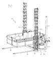
- the base 12 of the lifting platform 10 in the embodiment shown at least two vertical 22 and at least two horizontal profiles 24, of which in Fig. 1 only the right profile can be seen, while the respective left or rear profile covered by the platform 20 is.
- further profiles may be present below and behind the platform and that the profiles are interconnected to form a rigid base 12 which, as in FIG Fig. 1 shown, can be set up on a floor 14.
- the base is further provided, for example on its outer sides, with lifting masts 30.1, 30.2, which enable lifting of the platform 20 to a higher level via suitable drives.
- the masts 30 may be extendible.
- the lifting platform according to the invention is in Fig. 1 in a situation where she is already prepared for conversion to a console. This manifests itself in that in the two vertical profiles 22 each have a profile extension 26 is inserted from the top, which is displaceable in the profile 22, as soon as the lifting platform is raised. On the horizontal profiles 24 each have a second profile extension 28 is articulated by means of a hinge 34.
- the base can be placed with the already provided thereon profile extensions 26, 28 on the floor. Alternatively, it can be placed on the ground without said profile extensions, and these can be subsequently attached.
- the lifting platform is raised in total, ie including the base 12, so that the profile extensions 26 are displaced in the profiles 22, but remain substantially stationary, while the lifting platform is raised.
- FIG. 2 This condition is in Fig. 2 shown.
- the base 12 was raised, so that they, in Fig. 2 by way of example, located in the area of a lower building ceiling 18.2 of two building ceilings 18.1, 18.2.
- the profile extensions 26 have been pushed downwards by the profiles 22, so that a support of the base 12 by means of the further profile extensions 28 folded downwards in the meantime can be made on the profile extensions 26 pushed downwards.
- the base 12 has thus been converted to a console, which is suspended on a building, in the case shown on the lower ceiling 18.2 at a distance from the ground.
- a safety gate 36 is provided on the building ceilings 18.1, 18.2 to the lifting platform 10 out.
- shunting tables as in FIG Fig. 2 shown by way of example in the form of the switching table 38, are placed on the liftable platform 20 of the lifting platform 10.
- the masts 30 After lifting the Platform 20 by means of the masts 30 and suitable drives the GmbHisch 38 can be discharged to the higher building ceiling 18.1 and used there for shuttering the next building ceiling.
- the masts 30 can be further extended. In this context, they may be attached separately from the base 12 to one or more building decks 18.
- the lifting platform 10 can be brought to higher levels including the hanging on the building serving console 16 by the console is detached from the building ceiling 18.2, and brought for example by means of a crane to a higher level and hooked there.
- Fig. 3 and 4 shown lifting the console done by a climbing system.
- the embodiment of Fig. 3 corresponds to much of the embodiment described above with the exception that the vertical profiles 22, of which in the side view of Fig. 3 only one is visible, are designed as climbing profiles, which are provided in the example shown with the climbing climbing cam 40. It is understood that instead of the climbing cam 40 also protruding teeth, recesses, a hole profile, or other suitable contour can be used.
- the climbing cam 40 instead of the climbing cam 40 also protruding teeth, recesses, a hole profile, or other suitable contour can be used.
- FIGS. 1 and 2 Another difference between the embodiment of the Figures 3 and 4 and those of FIGS. 1 and 2 is that the vertical profile 22 by a pivotable profile extension 42 is extended, which is also designed as a climbing profile.
- a pivotable profile extension 42 In an area of the Horizontal profile 24, which is spaced from the building (see building ceilings 18), further profile extensions 28 are provided so that the in Fig. 3 shown base 12 can be converted to a console 16, the in Fig. 4 is shown.
- a plurality of feet 44 may be provided on the base 12, in particular on the horizontal profiles 24, which create a space below the base 12 to the bottom 14 in which the profile extensions 42 are receivable.
- bracket 16 is carried out in this embodiment, characterized in that the base 12 is raised, so that the profile extensions 28 can be folded into the area below the vertical profiles 22, and are subsequently bolted to the hinge point 46, so that they are rigidly interconnected.
- the climbing cam 40 By means of the climbing cam 40, the climbing profiles 22, 28 can be suspended in guide or wall shoes, which are attached to the building ceilings 18.
- suitable drives not shown
- the entire console can be raised, as described in detail in the referenced applications.
- a lifting by means of a crane is also possible for this embodiment.
- a guidance of the console by the engagement of the climbing profiles 22, 28, which may be embodied for example as I-profiles, with the wall or guide shoes, also possible when lifting by means of a crane.
Landscapes
- Engineering & Computer Science (AREA)
- Structural Engineering (AREA)
- Civil Engineering (AREA)
- Transportation (AREA)
- Automation & Control Theory (AREA)
- Conveying And Assembling Of Building Elements In Situ (AREA)
- Forklifts And Lifting Vehicles (AREA)
- Ropes Or Cables (AREA)
- Pallets (AREA)
Claims (18)
- Plate-forme de levage (10) dans le domaine de l'industrie du bâtiment, avec une base (12), susceptible d'être installée sur un sol (14) et convertible en une console (16), susceptible d'être accrochée à un ouvrage de construction (18), à une certaine distance du sol (14), et une plate-forme (20), susceptible d'être levée par rapport à la base (12), tant à l'état installée sur le sol (14), qu'également à l'état accrochée à l'ouvrage de construction (18).
- Plate-forme de levage selon la revendication 1,
caractérisée en ce que la base (12) présente au moins un profilé vertical (22) et/ou un profilé horizontal (24). - Plate-forme de levage selon la revendication 2,
caractérisée en ce qu'au moins un profilé vertical est réalisé sous forme de profilé grimpeur. - Plate-forme de levage selon la revendication 2 ou 3, en outre avec au moins un prolongement de profilé (26, 28), de préférence ajustable.
- Plate-forme de levage selon la revendication 4,
caractérisée en ce qu'au moins un prolongement de profilé est susceptible d'être enfiché dans un profilé (22) et/ou susceptible d'être monté de manière articulé sur un profilé (24). - Plate-forme de levage selon la revendication 5,
caractérisée en ce qu'au moins un prolongement de profilé (26) susceptible d'être enfiché est susceptible d'être déplacé dans le profilé (22). - Plate-forme de levage selon la revendication 5 ou 6,
caractérisée en ce qu'au moins un profilé (22) présente au moins un dispositif d'accrochage, à l'aide duquel la console (16) est susceptible d'être accrochée à l'ouvrage de construction (18) et/ou à un support monté sur lui. - Plate-forme de levage selon l'une des revendications 5 à 7,
caractérisée en ce qu'au moins un prolongement de profilé (28), susceptible d'être monté de manière articulée, présente au moins un dispositif d'appui, de préférence réglable. - Plate-forme de levage selon l'une des revendications précédentes, en outre avec au moins un mât de levage (30), de préférence pouvant être prolongé.
- Plate-forme de levage selon la revendication 9 et l'une des revendications 2 à 8,
caractérisée en ce que le mât de levage (30) est relié à au moins un profilé (22). - Plate-forme de levage selon l'une des revendications précédentes,
caractérisée en ce que la plate-forme est susceptible d'être élargie, en particulier est susceptible de subir une manoeuvre télescopique. - Procédé de construction d'une plate-forme de levage (10) dans le domaine de l'industrie du bâtiment, présentant une base (12) et une plate-forme (20), avec les étapes consistant à :- installer la base (12) sur un sol (14), de manière que la plate-forme (20) puisse être levée par rapport à la base (12),- lever la base (12),- convertir la base (12) en une console (16) susceptible d'être accrochée à un ouvrage de construction (18), et- accrocher la console (16) à l'ouvrage de construction (18), en un état tel que la plate-forme (20) puisse de nouveau être levée.
- Procédé selon la revendication 12,
caractérisé en ce que, dans le cadre de la conversion de la base, au moins un prolongement de profilé (26, 28), de préférence ajustable, est enfiché dans au moins un profilé (22) de la base (12) et/ou est monté de manière articulée sur un profilé (24) de la base (12). - Procédé selon la revendication 12 ou 13,
caractérisé en ce que, dans le cadre du levage de la base (12) et/ou de la conversion de la base (12), au moins un prolongement de profilé (26) est déplacé dans le profilé (22). - Procédé selon l'une des revendications 12 à 14,
caractérisé en ce qu'au moins un profilé (22) est accroché à l'ouvrage de construction (18) et/ou à un support monté sur lui. - Procédé selon l'une des revendications 12 à 15,
caractérisé en ce qu'une fonction de soutien, de préférence réglable, par rapport à un profilé ou un prolongement de profilé (26), est assurée à l'aide d'au moins un prolongement de profilé (28) pouvant être monté de manière articulée. - Procédé selon l'une des revendications 12 à 16, en outre avec l'étape consistant à : prolonger au moins un mât de levage (30).
- Procédé selon l'une des revendications 12 à 17, en outre avec l'étape consistant à : élargir, en particulier faire subir une manoeuvre télescopique à la plate-forme.
Applications Claiming Priority (2)
| Application Number | Priority Date | Filing Date | Title |
|---|---|---|---|
| DE102006029653A DE102006029653B4 (de) | 2006-06-28 | 2006-06-28 | Hubplattform und Verfahren zum Aufbauen einer Hubplattform |
| PCT/EP2007/056064 WO2008000654A1 (fr) | 2006-06-28 | 2007-06-19 | Plate-forme de levage et procédé de montage d'une plate-forme de levage |
Publications (2)
| Publication Number | Publication Date |
|---|---|
| EP2035314A1 EP2035314A1 (fr) | 2009-03-18 |
| EP2035314B1 true EP2035314B1 (fr) | 2010-12-22 |
Family
ID=38481952
Family Applications (1)
| Application Number | Title | Priority Date | Filing Date |
|---|---|---|---|
| EP07730243A Active EP2035314B1 (fr) | 2006-06-28 | 2007-06-19 | Plate-forme de levage et procédé de montage d'une plate-forme de levage |
Country Status (6)
| Country | Link |
|---|---|
| US (1) | US9212026B2 (fr) |
| EP (1) | EP2035314B1 (fr) |
| AT (1) | ATE492502T1 (fr) |
| DE (3) | DE102006029653B4 (fr) |
| ES (2) | ES1069076Y (fr) |
| WO (1) | WO2008000654A1 (fr) |
Families Citing this family (5)
| Publication number | Priority date | Publication date | Assignee | Title |
|---|---|---|---|---|
| US8480060B2 (en) * | 2010-01-15 | 2013-07-09 | T.B. Penick & Sons, Inc. | Crane cable roller assembly |
| CN102102438B (zh) * | 2010-09-20 | 2014-06-18 | 江苏申锡建筑机械有限公司 | 一种施工升降平台防倾翻装置 |
| CN101979800B (zh) * | 2010-10-29 | 2012-05-09 | 北京韬盛科技发展有限公司 | 电动爬升模板系统 |
| EP2487130B1 (fr) | 2011-02-14 | 2013-06-05 | Siemens Aktiengesellschaft | Protection statique contre les chutes pour un ascenseur à plateforme et ascenseur à plateforme en étant équipé |
| US9963889B2 (en) * | 2013-12-17 | 2018-05-08 | Shenzhen Techen Technology Co., Ltd | Sealed and integrated climbing scaffold and method for using the same |
Family Cites Families (16)
| Publication number | Priority date | Publication date | Assignee | Title |
|---|---|---|---|---|
| US3207263A (en) * | 1961-07-24 | 1965-09-21 | Civil & Civic Pty Ltd | Self-climbing formwork hoist |
| US3318414A (en) * | 1965-08-30 | 1967-05-09 | Ralph L Meek | Scaffolding |
| US3763964A (en) * | 1972-04-17 | 1973-10-09 | Equipment Syst Inc | Outside elevator |
| DE3006491C2 (de) * | 1980-02-21 | 1983-01-05 | Streif AG, 5461 Vettelschoß | Versetzbares, an einem Bauwerk verankertes Gerüst |
| US4496277A (en) * | 1982-04-12 | 1985-01-29 | Jungman, Inc. | Lifting device and method |
| CA1310041C (fr) * | 1988-06-14 | 1992-11-10 | John C. Preston | Echafaudage |
| US4892169A (en) * | 1989-02-21 | 1990-01-09 | Sinco, Inc. | Perimeter debris net lifting system |
| JP3131802B2 (ja) | 1992-04-27 | 2001-02-05 | 清水建設株式会社 | 下降式エレベータ |
| JP2565458B2 (ja) | 1992-10-07 | 1996-12-18 | 鹿島建設株式会社 | 揚重装置およびその使用方法 |
| DE4302197A1 (de) * | 1993-01-27 | 1994-07-28 | Peri Gmbh | Klettervorrichtung, insbesondere für ein Klettergerüst |
| DE4406987C1 (de) | 1994-03-03 | 1995-07-06 | Paul Lingen | Hubgerüst |
| AUPO685897A0 (en) * | 1997-05-16 | 1997-06-12 | Preston, John Clement | Partly retractable construction platform |
| US6170608B1 (en) * | 1998-12-02 | 2001-01-09 | Gressco Of Collier County, Inc. | Scaffold conveyor system |
| CA2317987A1 (fr) * | 2000-09-11 | 2002-03-11 | Jean G. Robillard | Plate-forme auto-elevatrice amelioree |
| DE102005045527A1 (de) | 2005-09-23 | 2007-04-19 | Doka Industrie Gmbh | Schutz- und Zugangsvorrichtung |
| DE102006026201B4 (de) | 2006-06-06 | 2008-04-10 | Doka Industrie Gmbh | Selbstklettersystem |
-
2006
- 2006-06-28 DE DE102006029653A patent/DE102006029653B4/de not_active Expired - Fee Related
-
2007
- 2007-06-19 ES ES200850008U patent/ES1069076Y/es not_active Expired - Lifetime
- 2007-06-19 US US12/306,451 patent/US9212026B2/en active Active
- 2007-06-19 DE DE212007000022U patent/DE212007000022U1/de not_active Expired - Lifetime
- 2007-06-19 ES ES07730243T patent/ES2355949T3/es active Active
- 2007-06-19 AT AT07730243T patent/ATE492502T1/de active
- 2007-06-19 DE DE502007006040T patent/DE502007006040D1/de active Active
- 2007-06-19 WO PCT/EP2007/056064 patent/WO2008000654A1/fr active IP Right Grant
- 2007-06-19 EP EP07730243A patent/EP2035314B1/fr active Active
Also Published As
| Publication number | Publication date |
|---|---|
| DE212007000022U1 (de) | 2008-08-28 |
| WO2008000654A1 (fr) | 2008-01-03 |
| DE102006029653A1 (de) | 2008-01-10 |
| ES1069076U (es) | 2009-01-16 |
| DE502007006040D1 (de) | 2011-02-03 |
| EP2035314A1 (fr) | 2009-03-18 |
| DE102006029653B4 (de) | 2009-02-12 |
| ATE492502T1 (de) | 2011-01-15 |
| US9212026B2 (en) | 2015-12-15 |
| ES1069076Y (es) | 2009-04-16 |
| US20090272604A1 (en) | 2009-11-05 |
| ES2355949T3 (es) | 2011-04-01 |
Similar Documents
| Publication | Publication Date | Title |
|---|---|---|
| DE2622840C2 (de) | Klettergerüst-Einheit mit zugehöriger Schalung | |
| WO2020020412A1 (fr) | Mécanisme de levage pour système grimpant guidé sur des rails | |
| EP3899167B1 (fr) | Dispositif de construction pourvu de coffrage grimpant et système d'ascenseur | |
| DE102007026020A1 (de) | Selbstklettersystem und Verfahren zum Betonieren eines Unterzugs und/oder Montieren eines Fertigteils mittels eines Selbstklettersystems | |
| EP2035314B1 (fr) | Plate-forme de levage et procédé de montage d'une plate-forme de levage | |
| DE7617464U1 (de) | Stuetzvorrichtung, insbesondere fuer traeger von schaleinrichtungen im betonbau | |
| DE1283484B (de) | Verfahren zum Bau von Hochhaeusern und Schalung zur Durchfuehrung des Verfahrens | |
| DE2217584C3 (de) | Kletterschalung für eine Betonwandschalung | |
| DE202008004374U1 (de) | Vorrichtung zum Abbrechen von Bauwerken | |
| DE102007021159B4 (de) | Rostdeckenschalung zur Einbindung einer Säule | |
| DE2050516A1 (de) | Senkrecht verstellbare Plattform fur Baugerüste | |
| DE3611431C2 (de) | Gerüststützeinrichtung für Gehwegüberbrückungen | |
| DE1534905A1 (de) | Vorrichtung zur Errichtung grosser konischer oder hyperbolischer Bauwerke,insbesondere Kuehltuerme | |
| DD244274A3 (de) | Geruest fuer reparaturarbeiten an fassaden und dachtraufen | |
| WO2022106485A1 (fr) | Rail d'escalade | |
| EP0105504A1 (fr) | Procédé et dispositif pour démonter des coffrages de plancher | |
| DE19704967C2 (de) | Portalkran, insbesondere zum Errichten von Bauwerken | |
| AT140282B (de) | Turmwagen mit Teleskopmast und Arbeitsbühne. | |
| EP3645443A1 (fr) | Système d'ascenseur | |
| EP1070806B1 (fr) | Système de plateforme | |
| DE10121957A1 (de) | Absturzsicherung für Baugerüste | |
| DE102004020345B4 (de) | Trägersystem für ein Konsolgerüst sowie Konsolgerüst aufweisend das Trägersystem | |
| WO2005085068A1 (fr) | Ensemble dock permettant l'execution de travaux sur un avion | |
| EP3560882A1 (fr) | Passage pour un ascenseur | |
| EP3839172A1 (fr) | Longeron garde-corps destiné au montage d'un garde-corps avant, garde-corps avant destiné à la protection temporaire contre les chutes d'un nouvel étage d'un échafaudage à créer, échafaudage pour travaux de construction, de réparation et/ou de montage et processus de construction d'un échafaudage |
Legal Events
| Date | Code | Title | Description |
|---|---|---|---|
| PUAI | Public reference made under article 153(3) epc to a published international application that has entered the european phase |
Free format text: ORIGINAL CODE: 0009012 |
|
| 17P | Request for examination filed |
Effective date: 20090123 |
|
| AK | Designated contracting states |
Kind code of ref document: A1 Designated state(s): AT BE BG CH CY CZ DE DK EE ES FI FR GB GR HU IE IS IT LI LT LU LV MC MT NL PL PT RO SE SI SK TR |
|
| AX | Request for extension of the european patent |
Extension state: AL BA HR MK RS |
|
| RBV | Designated contracting states (corrected) |
Designated state(s): AT DE ES GB IT |
|
| GRAP | Despatch of communication of intention to grant a patent |
Free format text: ORIGINAL CODE: EPIDOSNIGR1 |
|
| DAX | Request for extension of the european patent (deleted) | ||
| GRAS | Grant fee paid |
Free format text: ORIGINAL CODE: EPIDOSNIGR3 |
|
| GRAA | (expected) grant |
Free format text: ORIGINAL CODE: 0009210 |
|
| AK | Designated contracting states |
Kind code of ref document: B1 Designated state(s): AT DE ES GB IT |
|
| REG | Reference to a national code |
Ref country code: GB Ref legal event code: FG4D Free format text: NOT ENGLISH |
|
| REF | Corresponds to: |
Ref document number: 502007006040 Country of ref document: DE Date of ref document: 20110203 Kind code of ref document: P |
|
| REG | Reference to a national code |
Ref country code: DE Ref legal event code: R096 Ref document number: 502007006040 Country of ref document: DE Effective date: 20110203 |
|
| REG | Reference to a national code |
Ref country code: ES Ref legal event code: FG2A Ref document number: 2355949 Country of ref document: ES Kind code of ref document: T3 Effective date: 20110401 |
|
| PLBE | No opposition filed within time limit |
Free format text: ORIGINAL CODE: 0009261 |
|
| STAA | Information on the status of an ep patent application or granted ep patent |
Free format text: STATUS: NO OPPOSITION FILED WITHIN TIME LIMIT |
|
| 26N | No opposition filed |
Effective date: 20110923 |
|
| REG | Reference to a national code |
Ref country code: DE Ref legal event code: R097 Ref document number: 502007006040 Country of ref document: DE Effective date: 20110923 |
|
| PGFP | Annual fee paid to national office [announced via postgrant information from national office to epo] |
Ref country code: IT Payment date: 20140626 Year of fee payment: 8 |
|
| PGFP | Annual fee paid to national office [announced via postgrant information from national office to epo] |
Ref country code: GB Payment date: 20150624 Year of fee payment: 9 |
|
| PG25 | Lapsed in a contracting state [announced via postgrant information from national office to epo] |
Ref country code: IT Free format text: LAPSE BECAUSE OF NON-PAYMENT OF DUE FEES Effective date: 20150619 |
|
| GBPC | Gb: european patent ceased through non-payment of renewal fee |
Effective date: 20160619 |
|
| PG25 | Lapsed in a contracting state [announced via postgrant information from national office to epo] |
Ref country code: GB Free format text: LAPSE BECAUSE OF NON-PAYMENT OF DUE FEES Effective date: 20160619 |
|
| REG | Reference to a national code |
Ref country code: ES Ref legal event code: PC2A Owner name: DOKA GMBH Effective date: 20191220 |
|
| REG | Reference to a national code |
Ref country code: DE Ref legal event code: R082 Ref document number: 502007006040 Country of ref document: DE Representative=s name: HOFFMANN - EITLE PATENT- UND RECHTSANWAELTE PA, DE Ref country code: DE Ref legal event code: R081 Ref document number: 502007006040 Country of ref document: DE Owner name: DOKA GMBH, AT Free format text: FORMER OWNER: DOKA INDUSTRIE GMBH, AMSTETTEN, AT |
|
| P01 | Opt-out of the competence of the unified patent court (upc) registered |
Effective date: 20230517 |
|
| PGFP | Annual fee paid to national office [announced via postgrant information from national office to epo] |
Ref country code: DE Payment date: 20230620 Year of fee payment: 17 |
|
| PGFP | Annual fee paid to national office [announced via postgrant information from national office to epo] |
Ref country code: AT Payment date: 20230616 Year of fee payment: 17 |
|
| PGFP | Annual fee paid to national office [announced via postgrant information from national office to epo] |
Ref country code: ES Payment date: 20230719 Year of fee payment: 17 |