EP2034399B1 - Méthode de défilement pour un terminal mobile - Google Patents
Méthode de défilement pour un terminal mobile Download PDFInfo
- Publication number
- EP2034399B1 EP2034399B1 EP08163512.0A EP08163512A EP2034399B1 EP 2034399 B1 EP2034399 B1 EP 2034399B1 EP 08163512 A EP08163512 A EP 08163512A EP 2034399 B1 EP2034399 B1 EP 2034399B1
- Authority
- EP
- European Patent Office
- Prior art keywords
- displayed
- list
- mobile terminal
- boundary
- user
- Prior art date
- Legal status (The legal status is an assumption and is not a legal conclusion. Google has not performed a legal analysis and makes no representation as to the accuracy of the status listed.)
- Active
Links
- 238000000034 method Methods 0.000 title claims description 43
- 230000033001 locomotion Effects 0.000 claims description 69
- 230000000694 effects Effects 0.000 claims description 19
- 230000001133 acceleration Effects 0.000 claims description 17
- 238000004891 communication Methods 0.000 description 30
- 230000006870 function Effects 0.000 description 20
- 230000000007 visual effect Effects 0.000 description 12
- 230000005540 biological transmission Effects 0.000 description 8
- 238000010295 mobile communication Methods 0.000 description 8
- 238000003860 storage Methods 0.000 description 8
- 230000008569 process Effects 0.000 description 7
- 230000010355 oscillation Effects 0.000 description 6
- 230000008859 change Effects 0.000 description 5
- 238000010586 diagram Methods 0.000 description 5
- 238000012545 processing Methods 0.000 description 4
- 238000013459 approach Methods 0.000 description 3
- 238000013461 design Methods 0.000 description 3
- 238000001514 detection method Methods 0.000 description 3
- 239000007937 lozenge Substances 0.000 description 3
- 238000007726 management method Methods 0.000 description 3
- 238000012986 modification Methods 0.000 description 3
- 230000004048 modification Effects 0.000 description 3
- 230000003287 optical effect Effects 0.000 description 3
- 230000005236 sound signal Effects 0.000 description 3
- 241000257303 Hymenoptera Species 0.000 description 2
- 230000004397 blinking Effects 0.000 description 2
- 230000003139 buffering effect Effects 0.000 description 2
- 238000005516 engineering process Methods 0.000 description 2
- 239000004973 liquid crystal related substance Substances 0.000 description 2
- 239000000463 material Substances 0.000 description 2
- 229910052754 neon Inorganic materials 0.000 description 2
- GKAOGPIIYCISHV-UHFFFAOYSA-N neon atom Chemical compound [Ne] GKAOGPIIYCISHV-UHFFFAOYSA-N 0.000 description 2
- 229910001220 stainless steel Inorganic materials 0.000 description 2
- 239000010935 stainless steel Substances 0.000 description 2
- 230000003068 static effect Effects 0.000 description 2
- 239000010936 titanium Substances 0.000 description 2
- 238000012546 transfer Methods 0.000 description 2
- 101150012579 ADSL gene Proteins 0.000 description 1
- 102100020775 Adenylosuccinate lyase Human genes 0.000 description 1
- 108700040193 Adenylosuccinate lyases Proteins 0.000 description 1
- 101100521334 Mus musculus Prom1 gene Proteins 0.000 description 1
- RTAQQCXQSZGOHL-UHFFFAOYSA-N Titanium Chemical compound [Ti] RTAQQCXQSZGOHL-UHFFFAOYSA-N 0.000 description 1
- 230000004913 activation Effects 0.000 description 1
- 238000003491 array Methods 0.000 description 1
- 230000002238 attenuated effect Effects 0.000 description 1
- 238000012937 correction Methods 0.000 description 1
- 238000001746 injection moulding Methods 0.000 description 1
- 230000007774 longterm Effects 0.000 description 1
- 238000004519 manufacturing process Methods 0.000 description 1
- 230000007246 mechanism Effects 0.000 description 1
- 239000007769 metal material Substances 0.000 description 1
- 238000003909 pattern recognition Methods 0.000 description 1
- 238000003825 pressing Methods 0.000 description 1
- 238000013468 resource allocation Methods 0.000 description 1
- 230000002441 reversible effect Effects 0.000 description 1
- 230000035807 sensation Effects 0.000 description 1
- 238000001228 spectrum Methods 0.000 description 1
- 230000001629 suppression Effects 0.000 description 1
- 229920003002 synthetic resin Polymers 0.000 description 1
- 239000000057 synthetic resin Substances 0.000 description 1
- 239000010409 thin film Substances 0.000 description 1
- 229910052719 titanium Inorganic materials 0.000 description 1
Images


Classifications
-
- G—PHYSICS
- G06—COMPUTING; CALCULATING OR COUNTING
- G06F—ELECTRIC DIGITAL DATA PROCESSING
- G06F3/00—Input arrangements for transferring data to be processed into a form capable of being handled by the computer; Output arrangements for transferring data from processing unit to output unit, e.g. interface arrangements
- G06F3/01—Input arrangements or combined input and output arrangements for interaction between user and computer
- G06F3/048—Interaction techniques based on graphical user interfaces [GUI]
- G06F3/0487—Interaction techniques based on graphical user interfaces [GUI] using specific features provided by the input device, e.g. functions controlled by the rotation of a mouse with dual sensing arrangements, or of the nature of the input device, e.g. tap gestures based on pressure sensed by a digitiser
- G06F3/0488—Interaction techniques based on graphical user interfaces [GUI] using specific features provided by the input device, e.g. functions controlled by the rotation of a mouse with dual sensing arrangements, or of the nature of the input device, e.g. tap gestures based on pressure sensed by a digitiser using a touch-screen or digitiser, e.g. input of commands through traced gestures
-
- G—PHYSICS
- G06—COMPUTING; CALCULATING OR COUNTING
- G06F—ELECTRIC DIGITAL DATA PROCESSING
- G06F3/00—Input arrangements for transferring data to be processed into a form capable of being handled by the computer; Output arrangements for transferring data from processing unit to output unit, e.g. interface arrangements
- G06F3/01—Input arrangements or combined input and output arrangements for interaction between user and computer
- G06F3/048—Interaction techniques based on graphical user interfaces [GUI]
- G06F3/0484—Interaction techniques based on graphical user interfaces [GUI] for the control of specific functions or operations, e.g. selecting or manipulating an object, an image or a displayed text element, setting a parameter value or selecting a range
- G06F3/0485—Scrolling or panning
-
- G—PHYSICS
- G06—COMPUTING; CALCULATING OR COUNTING
- G06F—ELECTRIC DIGITAL DATA PROCESSING
- G06F3/00—Input arrangements for transferring data to be processed into a form capable of being handled by the computer; Output arrangements for transferring data from processing unit to output unit, e.g. interface arrangements
- G06F3/01—Input arrangements or combined input and output arrangements for interaction between user and computer
- G06F3/016—Input arrangements with force or tactile feedback as computer generated output to the user
-
- G—PHYSICS
- G06—COMPUTING; CALCULATING OR COUNTING
- G06F—ELECTRIC DIGITAL DATA PROCESSING
- G06F3/00—Input arrangements for transferring data to be processed into a form capable of being handled by the computer; Output arrangements for transferring data from processing unit to output unit, e.g. interface arrangements
- G06F3/01—Input arrangements or combined input and output arrangements for interaction between user and computer
- G06F3/048—Interaction techniques based on graphical user interfaces [GUI]
- G06F3/0481—Interaction techniques based on graphical user interfaces [GUI] based on specific properties of the displayed interaction object or a metaphor-based environment, e.g. interaction with desktop elements like windows or icons, or assisted by a cursor's changing behaviour or appearance
- G06F3/0482—Interaction with lists of selectable items, e.g. menus
-
- H—ELECTRICITY
- H04—ELECTRIC COMMUNICATION TECHNIQUE
- H04M—TELEPHONIC COMMUNICATION
- H04M1/00—Substation equipment, e.g. for use by subscribers
- H04M1/26—Devices for calling a subscriber
- H04M1/27—Devices whereby a plurality of signals may be stored simultaneously
- H04M1/274—Devices whereby a plurality of signals may be stored simultaneously with provision for storing more than one subscriber number at a time, e.g. using toothed disc
- H04M1/2745—Devices whereby a plurality of signals may be stored simultaneously with provision for storing more than one subscriber number at a time, e.g. using toothed disc using static electronic memories, e.g. chips
- H04M1/27467—Methods of retrieving data
- H04M1/2747—Scrolling on a display
-
- H—ELECTRICITY
- H04—ELECTRIC COMMUNICATION TECHNIQUE
- H04M—TELEPHONIC COMMUNICATION
- H04M1/00—Substation equipment, e.g. for use by subscribers
- H04M1/72—Mobile telephones; Cordless telephones, i.e. devices for establishing wireless links to base stations without route selection
- H04M1/724—User interfaces specially adapted for cordless or mobile telephones
- H04M1/72469—User interfaces specially adapted for cordless or mobile telephones for operating the device by selecting functions from two or more displayed items, e.g. menus or icons
-
- Y—GENERAL TAGGING OF NEW TECHNOLOGICAL DEVELOPMENTS; GENERAL TAGGING OF CROSS-SECTIONAL TECHNOLOGIES SPANNING OVER SEVERAL SECTIONS OF THE IPC; TECHNICAL SUBJECTS COVERED BY FORMER USPC CROSS-REFERENCE ART COLLECTIONS [XRACs] AND DIGESTS
- Y10—TECHNICAL SUBJECTS COVERED BY FORMER USPC
- Y10S—TECHNICAL SUBJECTS COVERED BY FORMER USPC CROSS-REFERENCE ART COLLECTIONS [XRACs] AND DIGESTS
- Y10S715/00—Data processing: presentation processing of document, operator interface processing, and screen saver display processing
- Y10S715/973—Scroll tool, e.g. window scroll bar
Definitions
- the present invention relates to a user interface of a mobile terminal having a touch pad.
- a mobile terminal is a device that can be carried around and has one or more functions such as to perform voice and video call communication, inputting and outputting of information, storing data, and the like.
- the mobile terminal can support more complicated functions such as capturing images or video, reproducing music or video files, playing games, receiving broadcast signals, and the like.
- the mobile terminal may be embodied in the form of a multimedia player or device.
- the mobile terminal In order to implement various functions of such multimedia players or devices, the mobile terminal requires sufficient support in terms of hardware or software, for which numerous attempts are being made and implemented.
- a user interface (Ul) environment is provided to allow users to easily and conveniently search and select functions.
- US2007/146337 discloses a method of displaying a list wherein, when the end of the list is reached whilst scrolling, the direction of scrolling is reversed to produce a bounce effect.
- one object of the present invention is to address the above-noted and other requirements.
- Another object of the present invention is to provide a mobile terminal capable of providing to a user feedback upon reaching the end of a displayed menu list in a certain manner when the displayed menu list is scrolled according to a user manipulation, and a method for searching and providing feedback of a displayed menu.
- the present invention provides in one aspect a mobile terminal according to claim 1.
- the present invention provides in another aspect a scrolling method of a mobile terminal according to claim 6.
- a mobile terminal including: a manipulation unit; a display unit able to display a certain signal inputted via the manipulation unit; and a controller able to display a graphic effect on a certain region of a screen indicating the reaching of one end of a list displayed on the display unit when the displayed list is moved to the one end thereof.
- a mobile terminal including: a display unit available for a touch input; and a controller able to display a graphic effect on a certain region of a screen indicating the reaching of one end of a displayed list when the displayed list is moved to the one end thereof according to the touch input.
- a scrolling method of a mobile terminal including: sensing the inputting of a certain manipulation via an input unit; moving a displayed list to one end thereof according to the sensed manipulation input; and displaying a graphic effect on a certain region of a display screen when the list is moved to the one end thereof.
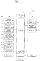
- FIG. 1 is a schematic block diagram of a mobile terminal implementing an embodiment of the present invention.
- the mobile terminal may be implemented in various forms.
- the described mobile terminal functionality may be implemented in portable devices such as mobile phones, smart phones, notebook computers, digital broadcast receivers, PDAs (Personal Digital Assistants), PMPs (Portable Multimedia Player), navigation devices, and the like, and in fixed type devices such as digital TVs, desktop computers, or the like.
- a terminal is assumed to be a mobile terminal, but it would be understood by a person in the art that the present invention can be also applicable to the fixed types of terminals except for any elements especially configured for a mobile purpose.
- the mobile terminal according to an embodiment of the present invention will now be described with reference to FIG. 1 .
- the mobile terminal 100 may include a wireless communication unit 110, an A/V (Audio/Video) input unit 120, a user input unit 130, a sensing unit 140, an output unit 150, a memory 160, an interface unit 170, a controller 180, and a power supply unit 190.
- A/V Audio/Video
- the mobile terminal 100 may include a wireless communication unit 110, an A/V (Audio/Video) input unit 120, a user input unit 130, a sensing unit 140, an output unit 150, a memory 160, an interface unit 170, a controller 180, and a power supply unit 190.
- A/V Audio/Video
- FIG. 1 shows the mobile terminal as having various components, but it should be understood that implementing all of the illustrated components is not a requirement. Greater or fewer components may alternatively be implemented.
- the wireless communication unit 110 typically includes one or more components allowing radio communication between the mobile terminal 100 and a wireless communication system or a network in which the mobile terminal is located.
- the wireless communication unit may include at least one of a broadcast receiving module 111, a mobile communication module 112, a wireless Internet module 113, a short-range communication module 114, and a location information module 115.
- the broadcast receiving module 111 receives broadcast signals and/or broadcast associated information from an external broadcast management server (or other network entity) via a broadcast channel.
- the broadcast channel may include a satellite channel and/or a terrestrial channel.
- the broadcast management server may be a server that generates and transmits a broadcast signal and/or broadcast associated information or a server that receives a previously generated broadcast signal and/or broadcast associated information and transmits the same to a terminal. Examples of the broadcast associated information may include information regarding a broadcast channel, a broadcast program, a broadcast service provider, etc.
- the broadcast signal may include a TV broadcast signal, a radio broadcast signal, a data broadcast signal, and the like. Also, the broadcast signal may further include a broadcast signal combined with a TV or radio broadcast signal.
- the broadcast associated information may also be provided via a mobile communication network (e.g., that operates according to standards such as 3GPP, 3GPP2, IEEE, CDMA, GSM, OMA, so-called 4G techniques, etc.) and, in this case, the broadcast associated information may be received by the mobile communication module 112.
- a mobile communication network e.g., that operates according to standards such as 3GPP, 3GPP2, IEEE, CDMA, GSM, OMA, so-called 4G techniques, etc.
- the broadcast signal may exist in various forms. For example, it may exist in the form of an electronic program guide (EPG) of digital multimedia broadcasting (DMB), electronic service guide (ESG) of digital video broadcast-handheld (DVB-H), and the like.
- EPG electronic program guide
- DMB digital multimedia broadcasting
- ESG electronic service guide
- DVB-H digital video broadcast-handheld
- the broadcast receiving module 111 may be configured to receive signals broadcast by using various types of broadcast systems.
- the broadcast receiving module 111 may receive a digital signal broadcast by using a digital broadcast system such as multimedia broadcasting-terrestrial (DMB-T), digital multimedia broadcasting-satellite (DMB-S), digital video broadcast-handheld (DVB-H), the data broadcasting system known as media forward link only (MediaFLO®), integrated services digital broadcast-terrestrial (ISDB-T), etc.
- the broadcast receiving module 111 is configured to be suitable for every broadcast system that provides a broadcast signal as well as the above-mentioned digital broadcast systems. Broadcast signals and/or broadcast-associated information received via the broadcast receiving module 111 may be stored in the memory 160 (or another type of storage medium).
- the mobile communication module 112 transmits and/or receives radio signals to and/or from at least one of a base station (e.g., access point, Node B, etc.), an external terminal (e.g., other user devices) and a server (or other network entities).
- a base station e.g., access point, Node B, etc.
- an external terminal e.g., other user devices
- a server or other network entities.
- radio signals may include a voice call signal, a video call signal or various types of data according to text and/or multimedia message transmission and/or reception.
- the wireless Internet module 113 supports wireless Internet access for the mobile terminal. This module may be internally or externally coupled to the terminal.
- the wireless Internet access technique implemented may include a WLAN (Wireless LAN) (Wi-Fi), Wibro (Wireless broadband), Wimax (World Interoperability for Microwave Access), HSDPA (High Speed Downlink Packet Access), or the like.
- the short-range communication module 114 is a module for supporting short range communications.
- Some examples of short-range communication technology include BluetoothTM, Radio Frequency IDentification (RFID), Infrared Data Association (IrDA), Ultra-WideBand (UWB), ZigBeeTM, and the like.
- the location information module 115 is a module for checking or acquiring a location (or position) of the mobile terminal.
- the location information module 115 may be embodied by using a GPS (Global Positioning System) module that receives location information from a plurality of satellites.
- the location information may include coordinate information represented by latitude and longitude values.
- the GPS module may measure an accurate time and distance from three or more satellites, and accurately calculate a current location of the mobile terminal according to trigonometry based on the measured time and distances.
- a method of acquiring distance and time information from three satellites and performing error correction with a single satellite may be used.
- the GPS module may acquire an accurate time together with three-dimensional speed information as well as the location of the latitude, longitude and altitude values from the location information received from the satellites.
- the A/V input unit 120 is configured to receive an audio or video signal.
- the A/V input unit 120 may include a camera 121 (or other image capture device) and a microphone 122 (or other sound pick-up device).
- the camera 121 processes image data of still pictures or video obtained by an image capture device in a video capturing mode or an image capturing mode.
- the processed image frames may be displayed on a display unit 151 (or other visual output device).
- the image frames processed by the camera 121 may be stored in the memory 160 (or other storage medium) or transmitted via the wireless communication unit 110. Two or more cameras 121 may be provided according to the configuration of the mobile terminal.
- the microphone 122 may receive sounds (audible data) via a microphone (or the like) in a phone call mode, a recording mode, a voice recognition mode, and the like, and can process such sounds into audio data.
- the processed audio (voice) data may be converted for output into a format transmittable to a mobile communication base station (or other network entity) via the mobile communication module 112 in case of the phone call mode.
- the microphone 122 may implement various types of noise canceling (or suppression) algorithms to cancel (or suppress) noise or interference generated in the course of receiving and transmitting audio signals.
- the user input unit 130 may generate key input data from commands entered by a user to control various operations of the mobile terminal.
- the user input unit 130 allows the user to enter various types of information, and may include a keypad, a dome switch, a touch pad (e.g., a touch sensitive member that detects changes in resistance, pressure, capacitance, etc. due to being contacted), a jog wheel, a jog switch, and the like.
- a touch pad e.g., a touch sensitive member that detects changes in resistance, pressure, capacitance, etc. due to being contacted
- a jog wheel e.g., a jog wheel
- a jog switch e.g., a jog switch
- the sensing unit 140 detects a current status (or state) of the mobile terminal 100 such as an opened or closed state of the mobile terminal 100, a location of the mobile terminal 100, the presence or absence of user contact with the mobile terminal 100 (i.e., touch inputs), the orientation of the mobile terminal 100, an acceleration or deceleration movement and direction of the mobile terminal 100, etc., and generates commands or signals for controlling the operation of the mobile terminal 100. For example, when the user touches the touch screen with his finger tip in a flicking manner to perform an operation of quickly moving a select menu (or a selection bar) or a cursor displayed thereon, the sensing unit 140 may sense the user's manipulation to generate a corresponding sense signal.
- a current status (or state) of the mobile terminal 100 such as an opened or closed state of the mobile terminal 100, a location of the mobile terminal 100, the presence or absence of user contact with the mobile terminal 100 (i.e., touch inputs), the orientation of the mobile terminal 100, an acceleration or deceleration movement and direction of the
- the sensing unit 140 may sense whether the slide phone is opened or closed. In addition, the sensing unit 140 can detect whether or not the power supply unit 190 supplies power or whether or not the interface unit 170 is coupled with an external device.
- the sensing unit 140 may include a proximity sensor 141, which will be described in association with the touch screen.
- the interface unit 170 serves as an interface by which at least one external device may be connected with the mobile terminal 100.
- the external devices may include wired or wireless headset ports, an external power supply (or battery charger) ports, wired or wireless data ports, memory card ports, ports for connecting a device having an identification module, audio input/output (I/O) ports, video I/O ports, earphone ports, or the like.
- the identification module may be a memory chip (or other element with memory or storage capabilities) that stores various information for authenticating a user's authority for using the mobile terminal 100 and may include a user identity module (UIM), a subscriber identity module (SIM) a universal subscriber identity module (USIM), and the like.
- the device having the identification module (referred to as the 'identifying device', hereinafter) may take the form of a smart card. Accordingly, the identifying device may be connected with the terminal 100 via a port or other connection means.
- the interface unit 170 may be used to receive inputs (e.g., data, information, power, etc.) from an external device and transfer the received inputs to one or more elements within the mobile terminal 100 or may be used to transfer data between the mobile terminal and an external device.
- inputs e.g., data, information, power, etc.
- the interface unit 170 may serve as a conduit to allow power from the cradle to be supplied therethrough to the mobile terminal 100 or may serve as a conduit to allow various command signals inputted from the cradle to be transferred to the mobile terminal therethrough.
- Various command signals or power inputted from the cradle may operate as signals for recognizing when the mobile terminal is properly mounted on the cradle.
- the output unit 150 is configured to provide outputs in a visual, audible, and/or tactile manner (e.g., audio signal, video signal, alarm signal, vibration signal, etc.).
- the output unit 150 may include the display unit 151, an audio output module 152, an alarm unit 153, and the like.
- the display unit 151 may display information processed in the mobile terminal 100. For example, when the mobile terminal 100 is in a phone call mode, the display unit 151 may display a User Interface (Ul) or a Graphic User Interface (GUI) associated with a call or other communication (such as text messaging, multimedia file downloading, etc.). When the mobile terminal 100 is in a video call mode or image capturing mode, the display unit 151 may display a captured image and/or received image, a Ul or GUI that shows videos or images and functions related thereto, and the like.
- Ul User Interface
- GUI Graphic User Interface
- the display unit 151 may function as both an input device and an output device.
- the display unit 151 may include at least one of a Liquid Crystal Display (LCD), a Thin Film Transistor-LCD (TFT-LCD), an Organic Light Emitting Diode (OLED) display, a flexible display, a three-dimensional (3D) display, or the like. Some of them may be configured to be transparent to allow viewing of the exterior, which may be called transparent displays.
- a typical transparent display may be, for example, a TOLED (Transparent Organic Light Emitting Diode) display, or the like.
- the mobile terminal 100 may include two or more display units (or other display means) according to its particular desired embodiment. For example, the mobile terminal may include both an external display unit and an internal display unit.
- the touch screen may be configured to detect a touch input pressure as well as a touch input position and a touch input area.
- the touch screen may detect a user's touch and manipulation such as dragging, scrolling, flicking, or the like by interworking with the sensing unit 140.
- a proximity sensor 141 may be disposed within or near the touch screen.
- the proximity sensor 141 is a sensor for detecting the presence or absence of an object relative to a certain detection surface or an object that exists nearby by using the force of electromagnetism or infrared rays without a physical contact.
- the proximity sensor 141 has a considerably longer life span compared with a contact type sensor, and it can be utilized for various purposes.
- Examples of the proximity sensor 141 may include a transmission type photo sensor, a direct reflection type photo sensor, a mirror-reflection type photo sensor, an RF oscillation type proximity sensor, a capacitance type proximity sensor, a magnetic proximity sensor, an infrared proximity sensor, and the like.
- the operational principle of the RF oscillation type proximity sensor will be described as an example.
- an object approaches the sensor detection surface in a state that an RF (Radio Frequency) of a static wave is oscillated by an oscillation circuit
- the oscillation amplitude of the oscillation circuit is attenuated or stopped, and such a change is converted into an electrical signal to detect the presence or absence of an object.
- a proximity switch can detect the object intended to be detected without an interference by the object.
- the proximity sensor 141 Without the proximity sensor 141, if the touch screen is an electrostatic type, the approach of a pointer (stylus) can be detected based on a change in a field according to the approach of the pointer.
- the pointer is not actually brought into contact with the touch screen but merely positioned close to the touch screen, the position of the pointer and the distance between the pointer and the touch screen can be detected.
- recognition of the pointer positioned to be close to the touch screen will be called a 'proximity touch', while recognition of actual contacting of the pointer on the touch screen will be called a 'contact touch'.
- the pointer when the pointer is in the state of the proximity touch, it means that the pointer is positioned to correspond vertically to the touch screen.
- a proximity touch and a proximity touch pattern e.g., a proximity touch distance, a proximity touch speed, a proximity touch time, a proximity touch position, a proximity touch movement state, or the like
- a proximity touch and a proximity touch pattern can be detected, and information corresponding to the detected proximity touch operation and the proximity touch pattern can be outputted to the touch screen.
- the audio output module 152 may convert and output as sound audio data received from the wireless communication unit 110 or stored in the memory 160 in a call signal reception mode, a call mode, a record mode, a voice recognition mode, a broadcast reception mode, and the like. Also, the audio output module 152 may provide audible outputs related to a particular function performed by the mobile terminal 100 (e.g., a call signal reception sound, a message reception sound, etc.). The audio output module 152 may include a speaker, a buzzer, or other sound generating device.
- the alarm unit 153 may provide outputs to inform about the occurrence of an event of the mobile terminal 100. Typical events may include call reception, message reception, key signal inputs, a touch input etc. In addition to audio or video outputs, the alarm unit 153 may provide outputs in a different manner to inform about the occurrence of an event. For example, the alarm unit 153 may provide an output in the form of vibrations (or other tactile or sensible outputs). When a call, a message, or some other incoming communication is received, the alarm unit 153 may provide tactile outputs (i.e., vibrations) to inform the user thereof. By providing such tactile outputs, the user can recognize the occurrence of various events even if his mobile phone is in the user's pocket. Outputs informing about the occurrence of an event may be also provided via the display unit 151 or the audio output module 152.
- the memory 160 may store software programs or the like used for the processing and controlling operations performed by the controller 180, or may temporarily store data (e.g., a phonebook, messages, still images, video, etc.) that have been inputted or which are to be outputted.
- the memory 160 may store data regarding various patterns of vibrations and audio signals to be outputted when a touch is applied to the touch screen.
- the memory 160 may include at least one type of storage medium including a Flash memory, a hard disk, a multimedia card, a card-type memory (e.g., SD or DX memory, etc), a Random Access Memory (RAM), a Static Random Access Memory (SRAM), a Read-Only Memory (ROM), an Electrically Erasable Programmable Read-Only Memory (EEPROM), a Programmable Read-Only Memory (PROM), a magnetic memory, a magnetic disk, an optical disk, and the like. Also, the mobile terminal 100 may cooperate with a network storage device that performs the storage function of the memory 160 over a network connection.
- a network storage device that performs the storage function of the memory 160 over a network connection.
- the controller 180 typically controls the general operations of the mobile terminal. For example, the controller 180 performs controlling and processing associated with voice calls, data communications, video calls, and the like.
- the controller 180 may include a multimedia module 181 for reproducing (or playing back) multimedia data.
- the multimedia module 181 may be configured within the controller 180 or may be configured to be separate from the controller 180.
- the controller 180 may perform a pattern recognition processing to recognize a handwriting input or a picture drawing input performed on the touch screen as characters or images.
- the power supply unit 190 receives external power (via a power cable connection) or internal power (via a battery of the mobile terminal) and supplies appropriate power required for operating respective elements and components under the control of the controller 180.
- Various embodiments as described herein may be implemented in a computer-readable medium using, for example, computer software, hardware, or any combination thereof.
- the embodiments described herein may be implemented by using at least one of application specific integrated circuits (ASICs), digital signal processors (DSPs), digital signal processing devices (DSPDs), programmable logic devices (PLDs), field programmable gate arrays (FPGAs), processors, controllers, micro-controllers, microprocessors, electronic units designed to perform the functions described herein. In some cases, such embodiments may be implemented in the controller 180.
- ASICs application specific integrated circuits
- DSPs digital signal processors
- DSPDs digital signal processing devices
- PLDs programmable logic devices
- FPGAs field programmable gate arrays
- processors controllers, micro-controllers, microprocessors, electronic units designed to perform the functions described herein.
- controller 180 such embodiments may be implemented in the controller 180.
- the embodiments such as procedures or functions may be implemented together with separate software modules that allow performing of at least one function or operation.
- Software codes can be implemented by a software application (or program) written in any suitable programming language.
- the software codes may be stored in the memory 160 and executed by the controller 180.
- the mobile terminal may be implemented in a variety of different configurations. Examples of such configurations include folder-type, bar-type, swing-type, a slide type, as well as various other configurations. The following description will primarily relate to a slide-type mobile terminal. However, such description can equally apply to other types of mobile terminals.
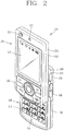
- FIG. 2 is a front perspective view of the mobile terminal according to an embodiment of the present invention.
- the mobile terminal 100 includes a first body 200, and a second body 205 that can be slidably moved along at least one direction with respect to the first body 200.
- the mobile terminal 100 may include a first body and a second body having one side that can be folded or unfolded with respect to the first body.
- a state in which the first body is disposed to overlap with the second body 205 may be called a closed configuration, and as shown in FIG. 2 , a state in which at least a portion of the second body 205 is exposed may be called an open configuration.
- the mobile terminal according to the present invention may be the folder type mobile terminal including the first body and the second body having one side to be folded or unfolded with respect to the first body.
- a state in which the second body is folded may be called a closed configuration
- a state in which the second body is unfolded may be called an open configuration.
- the mobile terminal according to the present invention may be a swing type mobile terminal including a first body and a second body configured to be swingable with respect to the first body.
- a state in which the first body is disposed to overlap with the second body may be called a closed configuration
- a state in which the second body is swung to expose a portion of the first body may be called an open configuration.
- the folder type mobile terminal and the swing type mobile terminal can be easily know by the person in the art without any explanation, so its detailed description will be omitted.
- the mobile terminal In the closed configuration, the mobile terminal mainly operates in a standby (or idle) mode, and the standby mode may be released upon user manipulation.
- the mobile terminal operates mainly in the calling mode or the like in the open configuration, and it can be changed to the standby mode with the lapse of time or upon user manipulation.
- the case (or casing, housing, cover, etc.) constituting the external appearance of the first body 200 may include a first front case 220 and a first rear case 225.
- Various electronic components are installed in the space between the first front case 220 and the first rear case 225.
- One or more intermediate cases may be additionally disposed between the first front case 220 and the first rear case 225.
- the cases may be formed by injection-molding a synthetic resin or may be made of a metallic material such as stainless steel (STS) or titanium (Ti), etc.
- STS stainless steel
- Ti titanium
- the display unit 151, the audio output module 152, the camera 121 or the first user input unit 210 may be located at the first body, 200, specifically, on the first front case 220 of the first body 200.
- the display unit 151 may include an LCD (Liquid Crystal Display), an OLED (Organic Light Emitting Diode), and the like, that visually displays information.
- LCD Liquid Crystal Display
- OLED Organic Light Emitting Diode
- a touch pad may be overlaid in a layered manner on the display unit 151 to allow the display unit 151 to function as a touch screen to input information via user gestures or touch inputs.
- the audio output unit 152 may be implemented in the form of a speaker or other sound producing device.
- the camera 121 may be implemented to be suitable for capturing images or video with respect to the user and other objects.
- the case constituting the external appearance of the second body 205 may include a second front case 230 and a second rear case 235.
- a second user input unit 215 may be disposed at the second body, specifically, at a front face of the second body 205.
- a third user input unit 245, the microphone 122, the interface unit 170 may be disposed on at least one of the second front case 230 and the second rear case 235.
- the first to third user input units 210, 215 and 245 may be generally referred to as a manipulating portion130, and various methods and techniques can be employed for the manipulation unit so long as they can be operated by the user in a tactile manner.
- the user input units 130 can be implemented as dome switches, actuators, or touch pad regions that can receive user commands or information according to the user's touch operations (e.g., pressing, pushing, swiping, drag-and-drop, etc.) or may be implemented in the form of a rotatable control wheel (or disc), keys or buttons, a jog dial, a joystick, or the like.
- touch operations e.g., pressing, pushing, swiping, drag-and-drop, etc.
- a rotatable control wheel or disc
- keys or buttons e.g., a jog dial, a joystick, or the like.
- the first user input unit 210 is used for inputting (entering) commands such as start, end, scroll or the like
- the second user input unit 215 is used for inputting (entering) numbers, characters, symbols, or the like.
- the first user input unit 210 may include a soft key used by interworking with icons displayed on the display unit 151 and navigation key (largely including four direction keys and a central key) for indicating and checking directions.
- the third user input unit 245 may support the so-called hot key functions that allow more convenient activation of particular functions for the mobile terminal.
- the microphone 122 (or other sound pick-up device) may be appropriately implemented to detect user voice inputs, other sounds, and the like.
- the interface unit 170 may be used as a communication link (or passage, path, etc.) through which the terminal can exchange data or the like with an external device.
- the interface unit 170 may be implemented in the form of a connection port for connecting an earphone to the mobile terminal via a fixed or wireless means, a port for short-range communications (e.g., an Infrared Data Association (IrDA) port, a BluetoothTM port, a wireless LAN port, etc.), power supply ports for providing power to the mobile terminal, or the like.
- IrDA Infrared Data Association
- the interface unit 170 may be a card socket for accommodating a SIM (Subscriber Identification Module) card or a UIM (User Identity Module) card, or an external card such as a memory card for storing information.
- SIM Subscriber Identification Module
- UIM User Identity Module
- the power supply unit 190 for supplying power to the terminal may be located at the second rear case 235.
- the power supply unit 190 may be, for example, a rechargeable battery that can be detached.
- FIG. 3 is a rear perspective view of the mobile terminal of FIG. 2 according to an exemplary embodiment.
- a camera 121 (or other image pick-up device) may additionally be disposed on a rear surface of the second rear case 235 of the second body 205.
- the camera 121 of the second body 205 may have an image capture direction which is substantially opposite to that of the camera 121 of the first body 200 (namely, the two cameras may be implemented to face towards opposing directions, such as front and rear), and may support a different number of pixels (i.e., have a different resolution) than the camera 121 of the first body.
- the camera of the first body 200 may operate with a relatively lower resolution to capture an image(s) of the user's face and immediately transmit such image(s) to another party in real-time during video call communication or the like in which reverse link bandwidth capabilities may be limited.
- the camera of the second body 205 may operate with a relatively higher resolution to capture images of general objects with high picture quality, which may not require immediately transmission in real-time, but may be stored for later viewing or use.
- Additional camera related components such as a flash 250 and a mirror 255, may be additionally disposed adjacent to the camera 121.
- the flash 250 illuminates the subject.
- the mirror 255 allows the user to see himself when he wants to capture his own image (i.e., self-image capturing) by using the camera 121 of the second body 205.
- the second rear case 235 may further include an audio output module 152.
- the audio output module 152 of the second body 205 may support stereophonic sound functions in conjunction with the audio output module 152 of the first body 200 and may be also used for sending and receiving calls in a speaker phone mode.
- a broadcast signal receiving antenna 260 may be disposed (externally or internally) at one side or region of the second rear case 235, in addition to an antenna that is used for mobile communications.
- the antenna 260 can also be configured to be retractable from the second body 205.
- One part of a slide module 265 that allows the first body 200 and the second body 205 to slide relative to each other may be disposed on the first rear case 225 of the first body 200.
- the other part of the slide module 265 may be disposed on the second front case 230 of the second body 205, which may not be exposed as shown in the drawing,
- the second camera 121 and other components may be disposed on the second body 205, but such configuration is not meant to be limited.
- one or more of the elements which are disposed on the second rear case 235 may be mounted on the first body 200, mainly, on the first rear case 225.
- those elements disposed on the first rear case 225 can be protected (or covered) by the second body 205 in the closed configuration.
- the camera module 121 may be configured to rotate (or otherwise be moved) to thus allow image capturing in various directions.
- the mobile terminal 100 as shown in FIGs. 1 to 3 may be configured to operate with a communication system, which transmits data via frames or packets, such as wired and wireless communication systems, as well as satellite-based communication systems.
- a communication system which transmits data via frames or packets, such as wired and wireless communication systems, as well as satellite-based communication systems.
- Such communication systems may use different air interfaces and/or physical layers.
- air interfaces utilized by the communication systems include example, frequency division multiple access (FDMA), time division multiple access (TDMA), code division multiple access (CDMA), and universal mobile telecommunications system (UMTS) (in particular, long term evolution (LTE)), global system for mobile communications (GSM), and the like.
- FDMA frequency division multiple access
- TDMA time division multiple access
- CDMA code division multiple access
- UMTS universal mobile telecommunications system
- LTE long term evolution
- GSM global system for mobile communications
- the description hereafter relates to a CDMA communication system, but such teachings apply equally to other types of systems.
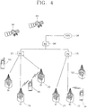
- a CDMA wireless communication system may include a plurality of mobile terminals 100, a plurality of base stations (BSs) 270, base station controllers (BSCs) 275, and a mobile switching center (MSC) 280.
- the MSC 280 is configured to interface with a public switch telephone network (PSTN) 290.
- PSTN public switch telephone network
- the MSC 280 is also configured to interface with the BSCs 275, which may be coupled to the base stations 270 via backhaul lines.
- the backhaul lines may be configured in accordance with any of several known interfaces including, for example, E1/T1, ATM, IP, PPP, Frame Relay, HDSL, ADSL, or xDSL. It is to be understood that the system as shown in FIG. 4 may include a plurality of BSCs 275.
- Each BS 270 may serve one or more sectors (or regions), each sector covered by an omni-directional antenna or an antenna pointed in a particular direction radially away from the BS 270. Alternatively, each sector may be covered by two or more antennas for diversity reception. Each BS 270 may be configured to support a plurality of frequency assignments, and each frequency assignment has a particular spectrum (e.g., 1.25 MHz, 5 MHz, etc).
- the intersection of a sector and frequency assignment may be referred to as a CDMA channel.
- the BS 270 may also be referred to as base station transceiver subsystems (BTSs) or other equivalent terms.
- BTSs base station transceiver subsystems
- the term "base station” may be used to collectively refer to a single BSC 275 and at least one BS 270.
- the base station may also be referred to as a "cell site”.
- individual sectors of a particular BS 270 may be referred to as a plurality of cell sites.
- a broadcasting transmitter (BT) 295 transmits a broadcast signal to the mobile terminals 100 operating within the system.
- the broadcast receiving module 111 as shown in FIG. 1 is provided at the terminal 100 to receive broadcast signals transmitted by the BT 295.
- GPS global positioning systems
- the GPS module 115 as shown in FIG. 1 is typically configured to cooperate with the satellites 300 to obtain desired positioning information.
- GPS tracking techniques instead of or in addition to GPS tracking techniques, other technologies that may track the location of the mobile terminals may be used.
- at least one of the GPS satellites 300 may selectively or additionally handle satellite DMB transmissions.
- the BSs 270 receive reverse-link signals from various mobile terminals 100.
- the mobile terminals 100 typically engaging in calls, messaging, and other types of communications.
- Each reverse-link signal received by a particular base station 270 is processed within the particular BS 270.
- the resulting data is forwarded to an associated BSC 275.
- the BSC provides call resource allocation and mobility management functionality including the coordination of soft handoff procedures between BSs 270.
- the BSCs 275 also route the received data to the MSC 280, which provides additional routing services for interfacing with the PSTN 290.
- the PSTN 290 interfaces with the MSC 280
- the MSC interfaces with the BSCs 275
- the BSCs 275 in turn control the BSs 270 to transmit forward-link signals to the mobile terminals 100.
- FIG. 5 is a view of a screen display or explaining how a flicking is performed on the touch screen of the mobile terminal.
- a flicking which is a user operation discriminated from dragging, means a user's touching on the touch screen in a flicking manner to quickly move a displayed menu list (or a selection bar) or a cursor. Because the displayed menu list can be moved up and down through flicking, the user can conveniently search for a desired menu item (e.g., content item 7). Thus, the flicking may be called a fast scrolling operation.
- An acceleration mechanism (or acceleration movement technique) is applied for the movement of the displayed menu list by the flicking.
- the acceleration movement technique refers to an animation (or a motion graphic image) technique in which the law of physical motion acceleration and deceleration is applied to the depiction of a movement of a particular object to provide a realistic imagery in implementing a GUI.
- the depicted acceleration movement of the displayed menu list (or selection bar) or the cursor is proportional to the force and speed of the user manipulation applied to the corresponding displayed menu list. Namely, when the user performs flicking, the movement speed of the displayed menu list is determined in consideration of a sensed distance, pressure, speed, etc., of the flicking.
- the user moves to a desired position of the displayed menu list by a slight touch or drag, and if there are tens of or hundreds of content items in the menu list and the user wants to quickly move to a desired position of the menu list, the user may flick at the displayed menu list with an appropriate force and speed to quickly move to the desired position.
- the user may believe that he has flicked the menu list with an appropriate force and speed, he may not reach the last item of displayed the menu list, or he may reach the last item of the menu list with such a strong acceleration movement as to pass beyond a lower end of the screen display because of an excessive force or speed.
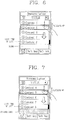
- FIG. 6 shows an example of a visual feedback method with respect to reaching the end of the displayed menu list in performing flicking according to the present invention.
- a picture or a discriminated color region may be displayed at both ends of the list.
- FIG. 7 shows another example of a visual feedback method with respect to the reaching of the end of the displayed menu list in a flicking operation according to the present invention.
- a border of a certain color is displayed at a certain boundary contiguous with edge of, i.e., beyond, the last item of the menu list, namely, contiguous with the selection list, so that when the user reaches the last content item of the flicked menu list (or contents list) through an acceleration movement of a certain speed or faster, the user can visually recognize that it's the last item being displayed.
- both the blank space as depicted in FIG. 6 and the border as depicted in FIG. 7 may be displayed to increase the recognition effect of reaching the end of the displayed menu list.
- FIG. 8 shows still another example of a visual feedback method with respect to reaching the end of the displayed menu list in a flicking operation.
- the last item on the displayed menu list is discriminately displayed. Namely, the last item of the list may be colored or the color of an item adjacent to the last item on the list may be changed to inform the user about the end of the menu list.
- the reaching of the end of the menu list can be audibly informed.
- a certain sound is outputted as an audible feedback indication with respect to the reaching of the end of the menu list by using the alarm unit 153 or the audio output module 152 to audibly inform the user accordingly.
- the sound may include a voice, a mechanical sound, an intermittent sound or a continuous sound.
- the voice may be, for example, an announcement such as 'It's the last item of the list', and the sound may be 'ting' or a general alarm sound.
- the intermittent sound is a sound which is generated one time and then terminated, such as a 'ting'.
- the continuous sound refers to a sound form which is generated at an early stage of flicking and terminated upon reaching the last item of the menu list (or contents list).
- a sound for example, a frictional sound, may be generated when each displayed item of the menu list frictionally contacts with a bar 410 of a certain form or a rotational plate 420.
- FIG. 9 is a view showing an example of an audible feedback method with respect to the reaching of the end of a displayed menu list in a flicking operation. For example, reaching of the end of the menu list is indicated by generating a continuous sound.
- FIG. 9 shows the two types of patterns 410 and 420 contacting with the plurality of items on the menu list, but the present invention is not limited thereto, and various shapes may be applicable.
- feedback indication with respect to the reaching of end of the menu list may be made in a tactile manner as well as in the visual or audible manner as described above. Namely, when the last item of the flicked menu list is reached through an acceleration movement of a certain speed or faster, in the present invention, a vibration may be outputted as a feedback indication with respect to the end of the menu list by using the alarm unit 153 of the output unit 150.
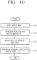
- FIG. 10 is a flow chart illustrating the process of a menu search feedback method according to an embodiment of the present invention.
- the controller 180 reads the contents menu list from the memory 160 and outputs it to the output unit 150 to display a plurality of items of the menu list on the display unit 151 (S10).
- the user may select a desired item on the menu list through a light touch or drag, or may quickly move to a different item on the menu list through flicking. If the user perform flicking, the sensing unit 140 detects the force and speed of the flicking and outputs corresponding information to the controller 180.
- the controller 180 detects whether or not a flicking has been generated based on the touch, force and speed detected by the sensing unit 140, and moves the displayed menu list in a corresponding direction according to the detected force and speed (S11).
- the controller 180 While the displayed menu list is being moved, the controller 180 checks whether the last item of the menu list is displayed on the screen. When the last item of the menu list is displayed, the controller 180 outputs a feedback to the user indicating that the last item of the menu list has been reached (S13). Preferably, the feedback is outputted by audio, video or vibration when a portion or the entirety of the end of the menu list is displayed.
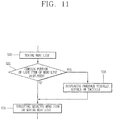
- FIG. 11 is a flow chart illustrating the process of a feedback output indicating the reaching of the end of the menu list in the menu search method in FIG. 10 .
- the controller 180 moves the displayed menu list in accordance with the force and speed detected by the sensing unit 140 (S20), and checks whether or not a certain portion of the last item of the menu list is displayed (S21).
- the controller 180 controls one or more of the display unit 151, the audio output module 152 and the alarm unit 153 to output a feedback indication for indicating to the user that the end of the menu list has been reached in a visual, audible and tactile (e.g., vibration) form (S22).
- a visual, audible and tactile e.g., vibration
- the controller 180 may execute a user selected menu item or detect flicking by the user and moves the displayed menu list again (S23).
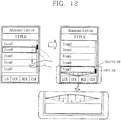
- FIG. 12 depicts the display of a motion graphic image generated at a lower edge portion of a screen display when a displayed selection bar reaches the last item of the displayed contents list (or display list) according to a flicking by the user according to one embodiment of the present invention.
- the user may flick the displayed selection bar with a proper force and speed.
- FIG. 12 shows the case where the selection bar reaches the last item of the displayed list due to an acceleration movement faster than a certain speed.
- the boundary contiguous with the last item at the lower portion of the screen is implemented as a motion graphic image having a wavy or oscillating shape graphically depicting or simulating a reaction or collision with the selected bar.
- the motion graphic image Through the motion graphic image, the user can visually recognize that there are no more items to be displayed on the list.
- the waving is expressed as the motion graphic image providing a visual sensation that the selection bar collides with the boundary through an acceleration movement faster than a certain speed to cause an impact waveform to appear.
- the impact waveform according to the collision is processed to be strongest at the center of the boundary and weakens by degree toward both the left and right ends.
- the size of the impact waveform (or waving) generated by the collision with the selection bar is proportional to the movement speed of the selection bar.
- the movement speed of the selection bar is determined by the distance, pressure and speed of a user touch detected on the touch screen.
- FIG. 12 shows the motion graphic image generated at the lower end portion of the screen, but such a motion graphic image can also be displayed at an upper end portion of the screen.
- a boundary contiguous with the first item at the upper portion of the screen display can be displayed as a motion graphic image having a wavy shape according to a collision with the selection bar.
- the selection bar reaches the left end or the right edge, such a motion graphic image can be displayed in the same manner.
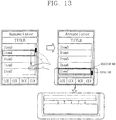
- FIG. 13 depicts the displaying of a motion graphic image according to another embodiment of the present invention.
- a motion graphic image display effect may be implemented such that a certain displayed boundary contiguous with the selection bar at a lower portion of the screen is thrust as it collides with the selection bar.
- the thrust degree of the boundary due to the collision with the selection bar is proportional to the movement speed of the displayed selection bar.
- Such a motion graphic image as shown in FIG. 13 may be also displayed in the same manner when the selection bar reaches a first item of the contents list (or the display list).
- a motion graphic image can be displayed in the same manner.
- a motion graphic image may be implemented such as to graphically depict that the boundary is temporarily compressed or contracted and then returns or expands to its original shape like a rebounding of an impact buffering member (e.g., a rubber material, etc.) with elasticity.
- an impact buffering member e.g., a rubber material, etc.
- the displayed selection bar immediately after the collision has a movement effect as if a ball bounces on the floor, on the certain boundary.
- An accompanying sound effect such as a 'boing' sound, or a vibration, may be generated and outputted to audibly or tactilly reinforce the visual effect.
- the motion graphic image when the flicked displayed selection bar makes an acceleration movement of a certain speed or faster, the motion graphic image can be displayed.
- the motion graphic images as shown in FIGs. 12 and 13 will be displayed when the flicked selection bar reaches the last item of the contents list through the acceleration movement at the certain speed or faster.
- the operation of controlling the movement of the selection bar (or cursor) according to an input e.g., dragging, scrolling, flicking, etc.
- an input e.g., dragging, scrolling, flicking, etc.
- the motion graphic effect according to the present invention can also be applied in the same manner even when the movement of the selection bar (or the cursor) is controlled through the manipulation portion 130 as well as by input through the touch screen.
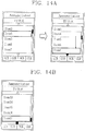
- FIG. 14A and FIG. 14B depict a screen display image of a contents list according to one embodiment of the present invention, in which directional symbols are displayed at upper and lower end portions of the displayed contents list.
- a directional symbol e.g., arrows ( ⁇ , ⁇ ), triangles ( ⁇ , ⁇ ), etc.
- the directional symbols e.g., the arrow ( ⁇ ), the triangle ( ⁇ ), etc.
- the directional symbols e.g., the arrow ( ⁇ ), the triangle ( ⁇ ), etc.
- the directional symbols are displayed at a lower end portion of the contents list screen display, it means that there are more undisplayed items of succeeding order, beyond the lower edge of the screen, than the contents of the displayed list appearing on the screen.
- the directional symbols displayed at the upper or lower end portions of the screen display may change according to the movement direction of the selection bar. For example, as shown in FIG. 14A , when the selection bar is moved downwardly, the directional symbol displayed at the lower portion of the screen changes (e.g., by color change, highlighting effect, blinking effect, effect of march of ants, neon sign effect, etc.). Likewise, when the selection bar is moved upwardly, the directional symbol displayed at the upper end portion of the screen changes.
- the directional symbol displayed at the lower end portion (or upper end portion) of the screen may be changed into a different shape, namely, a non-directional symbol (e.g., a square ( ⁇ or ⁇ ), a lozenge ( ⁇ or ⁇ ), or a circle ( ⁇ or o) as shown in FIG. 14B , through which the user can recognize whether or not the selection bar has reached the first item or the last item of the contents list.
- a non-directional symbol e.g., a square ( ⁇ or ⁇ ), a lozenge ( ⁇ or ⁇ ), or a circle ( ⁇ or o) as shown in FIG. 14B , through which the user can recognize whether or not the selection bar has reached the first item or the last item of the contents list.
- the directional symbols may be displayed on the screen, or the non-directional symbols (e.g., the square ( ⁇ or ⁇ ), the lozenge ( ⁇ or ⁇ ), the circle ( ⁇ or ⁇ ), etc.) may be displayed instead of the directional symbols.
- the non-directional symbols e.g., the square ( ⁇ or ⁇ ), the lozenge ( ⁇ or ⁇ ), the circle ( ⁇ or ⁇ ), etc.
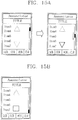
- FIG. 15A and FIG. 15B depict a screen image of a contents list according to another embodiment of the present invention.
- a translucent directional symbol e.g., arrows ( ⁇ , ⁇ ), triangles ( ⁇ , ⁇ ), etc.
- a translucent directional symbol e.g., arrows ( ⁇ , ⁇ ), triangles ( ⁇ , ⁇ ), etc.
- the directional symbol displayed at one portion of the screen is changed (e.g., by color change, highlighting, blinking, march of ants effect, neon sign effect, etc.) according to the movement direction (upwardly or downwardly) of the scroll bar.
- the directional symbol displayed at the upper or lower end portions of the screen can be changed into different translucent shapes (e.g., the square ( ⁇ or ⁇ ), the lozenge ( ⁇ or ⁇ ), or the circle ( ⁇ or ⁇ ), etc.) as shown in FIG. 15B , through which the user can recognize whether or not the selection bar has reached the first item or the last item of the contents list.
- both the directional symbol and the scroll bar can be displayed on the single screen, but the movement situation of the selection bar can also be displayed only with the directional symbols.
- the feedback indication for indicating the reaching of the end of the menu list can be outputted.
- the above-described embodiments may be implemented into fabrication methods, devices or products by using a reference programming and/or engineering technique to produce software, firmware, hardware or their combinations.
- the term 'product' as used herein refers to codes or logic implemented in hardware logic (e.g., FPGA, ASIC, etc.), a computer-readable medium (e.g., magnetic storage medium (e.g., a hard disk drive, a floppy disk, a tape, etc.), an optical memory (CD-ROMs, optical disk, etc.), and volatile/non-volatile memory unit (e.g., EEPROMs, ROMs, PROMs, RAMs, DRAMs, SRAMs, firmware, programmable logic, etc.).
- the codes within the computer-readable medium can be accessed and executed by a processor.
- the codes implemented according to the embodiments of the present invention can be accessible from transmission media or a file server of a network.
- the code-implemented product may include a network transmission line, wireless transmission media, and a transmission media such as signals, radio waves, or infrared signals transmitted via the space.
- a network transmission line such as signals, radio waves, or infrared signals transmitted via the space.
- the present invention is not limited to the slide type mobile terminal as shown in FIG. 1 but can be applicable to various types of mobile terminals such as bar type, folder type and swing type mobile terminals, and the like.
- the scrolling method of a mobile terminal according to the present invention has the following advantages.
- the displayed menu list movement is performed according to a flicking operation in a user interface environment of the mobile terminal having the touch screen or the touch pad
- the feedback for indicating the reaching of the end (the last item) of the menu list can be provided to the user, so the practicality of the terminal manipulation and the user convenience of menu searching can be enhanced.
Landscapes
- Engineering & Computer Science (AREA)
- General Engineering & Computer Science (AREA)
- Theoretical Computer Science (AREA)
- Human Computer Interaction (AREA)
- Physics & Mathematics (AREA)
- General Physics & Mathematics (AREA)
- Telephone Function (AREA)
- User Interface Of Digital Computer (AREA)
Claims (10)
- Terminal mobile comprenant :une unité d'affichage ayant un affichage d'écran ; etun dispositif de commande opérationnel pour afficher une liste incluant une pluralité d'éléments sur une région de l'affichage d'écran, la liste affichée ayant au moins une extrémité et une frontière contiguë avec l'au moins une extrémité de la liste affichée sur l'affichage d'écran,caractérisé en ce quele dispositif de commande est en outre configuré pour afficher sur la frontière une image graphique animée indiquant une collision entre un élément d'extrémité de la liste affichée et la frontière lorsque la liste affichée est déplacée vers l'au moins une extrémité selon une entrée tactile,dans lequel l'image graphique animée est affichée lorsque l'élément d'extrémité de la liste affichée est atteint avec un mouvement d'accélération plus rapide qu'une certaine vitesse,dans lequel l'image graphique animée est affichée tandis que l'élément d'extrémité de la liste est conservé au niveau de la frontière de la région.
- Terminal selon la revendication 1, dans lequel l'au moins une extrémité de la liste est l'une d'une extrémité supérieure, d'une extrémité inférieure, d'une extrémité gauche et d'une extrémité droite.
- Terminal selon la revendication 1, dans lequel l'entrée tactile est l'un d'un tapotement, d'un glissement et d'un défilement.
- Terminal selon la revendication 1, dans lequel le dispositif de commande affiche l'effet graphique selon la vitesse de déplacement de la liste affichée, lorsque la vitesse de déplacement de la liste affichée est plus rapide qu'une certaine vitesse, dans lequel l'effet graphique est un graphique animé ayant une forme telle que la frontière est ondulée.
- Terminal selon la revendication 1, dans lequel le dispositif de commande affiche l'effet graphique selon la vitesse de déplacement de la liste affichée, lorsque la vitesse de déplacement de la liste affichée est plus rapide qu'une certaine vitesse, dans lequel l'effet graphique est un graphique animé ayant une forme telle que la frontière est poussée dans une certaine direction.
- Procédé de défilement d'un terminal mobile comprenant :l'affichage d'une liste incluant une pluralité d'éléments sur une région d'une unité d'affichage, la liste affichée ayant au moins une extrémité et une frontière contiguë avec l'au moins une extrémité de la liste affichée sur l'affichage d'écran ;l'entrée d'une certaine entrée tactile via une unité d'entrée ;le déplacement de la liste affichée vers l'au moins une extrémité selon l'entrée ;caractérisé en ce que le procédé comprend en outre :l'affichage sur la frontière d'une image graphique animée indiquant une collision entre un élément d'extrémité de la liste affichée et la frontière si la liste affichée est déplacée vers l'au moins une extrémité,dans lequel l'image graphique animée est affichée lorsque l'élément d'extrémité de la liste affichée est atteint avec un mouvement d'accélération plus rapide qu'une certaine vitesse,dans lequel l'image graphique animée est affichée tandis que l'élément d'extrémité de la liste est conservé au niveau de la frontière de la région.
- Procédé selon la revendication 6, dans lequel la certaine entrée tactile est au moins l'un d'un tapotement, d'un glissement et d'un défilement.
- Procédé selon la revendication 6, dans lequel l'image graphique animée est affichée selon au moins l'un d'une vitesse de toucher, d'une zone de toucher, et d'un temps de toucher, et dans lequel l'au moins une extrémité de la liste est l'une d'une extrémité supérieure, d'une extrémité inférieure, d'une extrémité gauche et d'une extrémité droite.
- Procédé selon la revendication 6, dans lequel l'image graphique animée est un graphique animé ayant une forme telle que la frontière est ondulée.
- Procédé selon la revendication 6, dans lequel l'image graphique animée est un graphique animé ayant une forme telle que la frontière est poussée dans une certaine direction.
Applications Claiming Priority (2)
| Application Number | Priority Date | Filing Date | Title |
|---|---|---|---|
| KR1020070089670A KR100873679B1 (ko) | 2007-09-04 | 2007-09-04 | 휴대단말기의 스크롤링 방법 |
| KR1020070089686A KR101432587B1 (ko) | 2007-09-04 | 2007-09-04 | 휴대단말기 및 메뉴검색 피드백 방법 |
Publications (3)
| Publication Number | Publication Date |
|---|---|
| EP2034399A2 EP2034399A2 (fr) | 2009-03-11 |
| EP2034399A3 EP2034399A3 (fr) | 2012-12-12 |
| EP2034399B1 true EP2034399B1 (fr) | 2019-06-05 |
Family
ID=39760941
Family Applications (1)
| Application Number | Title | Priority Date | Filing Date |
|---|---|---|---|
| EP08163512.0A Active EP2034399B1 (fr) | 2007-09-04 | 2008-09-02 | Méthode de défilement pour un terminal mobile |
Country Status (2)
| Country | Link |
|---|---|
| US (1) | US9569088B2 (fr) |
| EP (1) | EP2034399B1 (fr) |
Families Citing this family (92)
| Publication number | Priority date | Publication date | Assignee | Title |
|---|---|---|---|---|
| KR100803784B1 (ko) * | 2006-11-24 | 2008-02-15 | 삼성전자주식회사 | 슬라이딩/스윙 모듈 및 그를 구비하는 휴대용 단말기 |
| JP5357464B2 (ja) * | 2008-08-26 | 2013-12-04 | アルパイン株式会社 | メニュー表示装置及びメニュー表示方法 |
| US8686951B2 (en) | 2009-03-18 | 2014-04-01 | HJ Laboratories, LLC | Providing an elevated and texturized display in an electronic device |
| KR101646922B1 (ko) | 2009-05-19 | 2016-08-23 | 삼성전자 주식회사 | 휴대 단말기의 통신 관련 기능 운용 방법 및 이를 지원하는 휴대 단말기 |
| KR101576292B1 (ko) * | 2009-05-21 | 2015-12-09 | 엘지전자 주식회사 | 이동 통신 단말기에서의 메뉴 실행 방법 및 이를 적용한 이동 통신 단말기 |
| TWI412963B (zh) * | 2009-07-01 | 2013-10-21 | Htc Corp | 資料顯示與移動方法及系統,及其電腦程式產品 |
| KR101588242B1 (ko) * | 2009-07-13 | 2016-01-25 | 삼성전자주식회사 | 휴대 단말기의 스크롤 방법 및 장치 |
| US8224391B2 (en) | 2009-07-20 | 2012-07-17 | Lg Electronics Inc. | Mobile terminal having an LED backlight unit |
| US8624925B2 (en) | 2009-10-16 | 2014-01-07 | Qualcomm Incorporated | Content boundary signaling techniques |
| US8677283B2 (en) * | 2009-10-21 | 2014-03-18 | Microsoft Corporation | Displaying lists as reacting against barriers |
| US8812985B2 (en) * | 2009-10-30 | 2014-08-19 | Motorola Mobility Llc | Method and device for enhancing scrolling operations in a display device |
| US9152318B2 (en) | 2009-11-25 | 2015-10-06 | Yahoo! Inc. | Gallery application for content viewing |
| DE102009058727A1 (de) * | 2009-12-17 | 2011-06-22 | Bayerische Motoren Werke Aktiengesellschaft, 80809 | Verfahren und Rechner zum Darstellen von Informationen auf einer Aufzeigevorrichtung eines Fahrzeugs |
| KR101725887B1 (ko) * | 2009-12-21 | 2017-04-11 | 삼성전자주식회사 | 터치 스크린 디바이스의 컨텐츠 검색 방법 및 장치 |
| JP5531612B2 (ja) * | 2009-12-25 | 2014-06-25 | ソニー株式会社 | 情報処理装置、情報処理方法、プログラム、制御対象機器および情報処理システム |
| US20110161892A1 (en) * | 2009-12-29 | 2011-06-30 | Motorola-Mobility, Inc. | Display Interface and Method for Presenting Visual Feedback of a User Interaction |
| US9417787B2 (en) * | 2010-02-12 | 2016-08-16 | Microsoft Technology Licensing, Llc | Distortion effects to indicate location in a movable data collection |
| US20110199342A1 (en) | 2010-02-16 | 2011-08-18 | Harry Vartanian | Apparatus and method for providing elevated, indented or texturized sensations to an object near a display device or input detection using ultrasound |
| US8448084B2 (en) * | 2010-04-08 | 2013-05-21 | Twitter, Inc. | User interface mechanics |
| KR101680113B1 (ko) * | 2010-04-22 | 2016-11-29 | 삼성전자 주식회사 | 휴대 단말기의 gui 제공 방법 및 장치 |
| US20110316805A1 (en) * | 2010-06-28 | 2011-12-29 | Youji Yamada | Electronic device |
| US20120026181A1 (en) * | 2010-07-30 | 2012-02-02 | Google Inc. | Viewable boundary feedback |
| KR20120019603A (ko) * | 2010-08-26 | 2012-03-07 | 삼성전자주식회사 | 터치 기반 입력 인터페이스를 가지는 터치 디바이스의 컨택트 리스트 제공 방법 및 장치 |
| JP5160604B2 (ja) * | 2010-09-14 | 2013-03-13 | 任天堂株式会社 | 表示制御プログラム、表示制御システム、表示制御装置、表示制御方法 |
| JP5478438B2 (ja) * | 2010-09-14 | 2014-04-23 | 任天堂株式会社 | 表示制御プログラム、表示制御システム、表示制御装置、表示制御方法 |
| JP5478439B2 (ja) * | 2010-09-14 | 2014-04-23 | 任天堂株式会社 | 表示制御プログラム、表示制御システム、表示制御装置、表示制御方法 |
| US8514252B1 (en) | 2010-09-22 | 2013-08-20 | Google Inc. | Feedback during crossing of zoom levels |
| JP5668401B2 (ja) * | 2010-10-08 | 2015-02-12 | ソニー株式会社 | 情報処理装置、情報処理方法およびプログラム |
| JP5679169B2 (ja) * | 2010-10-20 | 2015-03-04 | 株式会社ソニー・コンピュータエンタテインメント | メニュー表示装置、メニュー表示制御方法及びプログラム |
| US9043732B2 (en) * | 2010-10-21 | 2015-05-26 | Nokia Corporation | Apparatus and method for user input for controlling displayed information |
| CN102681746B (zh) * | 2011-03-08 | 2016-08-03 | 腾讯科技(深圳)有限公司 | 一种操作手持设备中列表的方法及装置 |
| US8863039B2 (en) | 2011-04-18 | 2014-10-14 | Microsoft Corporation | Multi-dimensional boundary effects |
| US9229604B2 (en) * | 2011-09-01 | 2016-01-05 | Sony Corporation | User interface element |
| WO2013039064A1 (fr) * | 2011-09-13 | 2013-03-21 | 株式会社ソニー・コンピュータエンタテインメント | Dispositif de traitement d'informations, procédé de commande d'affichage, programme et support de stockage d'informations |
| US20130117698A1 (en) * | 2011-10-31 | 2013-05-09 | Samsung Electronics Co., Ltd. | Display apparatus and method thereof |
| JP5887932B2 (ja) * | 2011-12-28 | 2016-03-16 | コニカミノルタ株式会社 | 画像処理装置、画像処理装置の制御方法、および制御プログラム |
| TWI476674B (zh) | 2012-02-24 | 2015-03-11 | Htc Corp | 電子裝置及其操作方法以及電腦可讀取儲存媒體 |
| EP2632119A1 (fr) * | 2012-02-27 | 2013-08-28 | Doro AB | UI linéaire d'accès bimodal |
| JP5994412B2 (ja) * | 2012-06-13 | 2016-09-21 | 富士ゼロックス株式会社 | 画像表示装置、画像制御装置、画像形成装置およびプログラム |
| US8607156B1 (en) * | 2012-08-16 | 2013-12-10 | Google Inc. | System and method for indicating overscrolling in a mobile device |
| JP6004855B2 (ja) * | 2012-09-14 | 2016-10-12 | キヤノン株式会社 | 表示制御装置及びその制御方法 |
| JP6251948B2 (ja) * | 2012-10-03 | 2017-12-27 | コニカミノルタ株式会社 | 表示装置、画像形成装置、および表示制御プログラム |
| US9075519B2 (en) * | 2012-10-11 | 2015-07-07 | Apple Inc. | System and method for interacting with a displayed work space |
| JP6025493B2 (ja) * | 2012-10-15 | 2016-11-16 | キヤノン株式会社 | 表示処理装置、制御方法およびコンピュータプログラム |
| WO2014063834A1 (fr) | 2012-10-22 | 2014-05-01 | Telefónica, S.A. | Procédé mis en œuvre sur ordinateur et dispositif électronique pour fournir une rétroaction visuelle à un utilisateur lorsque le bord d'un objet a été atteint |
| JP5817708B2 (ja) * | 2012-11-22 | 2015-11-18 | コニカミノルタ株式会社 | 画像処理装置、画像処理装置の制御方法、および画像処理装置の制御プログラム |
| KR101272867B1 (ko) * | 2012-11-30 | 2013-06-10 | (주)인스웨이브시스템즈 | 모바일 단말기의 그리드 출력 장치 및 그 방법 |
| KR102174916B1 (ko) | 2012-11-30 | 2020-11-05 | 삼성전자주식회사 | 종료 효과를 표시하는 모바일 장치 및 그 제어방법 |
| TW201433971A (zh) * | 2013-02-20 | 2014-09-01 | Phoenix Tech Ltd | 電子文件邊界提醒方法 |
| US9842571B2 (en) | 2013-02-22 | 2017-12-12 | Samsung Electronics Co., Ltd. | Context awareness-based screen scroll method, machine-readable storage medium and terminal therefor |
| KR102074347B1 (ko) * | 2013-03-15 | 2020-03-02 | 엘지전자 주식회사 | 이동 단말기 및 그것의 제어방법 |
| US20140282146A1 (en) * | 2013-03-15 | 2014-09-18 | Samsung Electronics Co. Ltd. | Use of perspective to improve visual information density |
| US20140325429A1 (en) * | 2013-04-25 | 2014-10-30 | Hung-Sen Chang | Method for controlling the display of a document shown on a touch device |
| CN103309673B (zh) * | 2013-06-24 | 2017-03-01 | 小米科技有限责任公司 | 一种基于手势的会话处理方法、装置 |
| CN104298436B (zh) * | 2013-07-15 | 2019-03-01 | 腾讯科技(深圳)有限公司 | 一种快捷回复操作方法和终端 |
| EP3605286B1 (fr) * | 2013-09-03 | 2021-02-17 | Apple Inc. | Interface utilisateur pour la manipulation d'objets d'interface utilisateur |
| US11068128B2 (en) | 2013-09-03 | 2021-07-20 | Apple Inc. | User interface object manipulations in a user interface |
| US10545657B2 (en) | 2013-09-03 | 2020-01-28 | Apple Inc. | User interface for manipulating user interface objects |
| US10503388B2 (en) | 2013-09-03 | 2019-12-10 | Apple Inc. | Crown input for a wearable electronic device |
| EP3125090B1 (fr) * | 2014-03-25 | 2020-04-01 | Sony Corporation | Dispositif de commande d'affichage, procédé de commande d'affichage et programme |
| USD763882S1 (en) * | 2014-04-25 | 2016-08-16 | Tencent Technology (Shenzhen) Company Limited | Portion of a display screen with animated graphical user interface |
| USD765110S1 (en) * | 2014-04-25 | 2016-08-30 | Tencent Technology (Shenzhen) Company Limited | Portion of a display screen with animated graphical user interface |
| CN116301544A (zh) | 2014-06-27 | 2023-06-23 | 苹果公司 | 尺寸减小的用户界面 |
| KR20160020738A (ko) * | 2014-08-14 | 2016-02-24 | 삼성전자주식회사 | 전자 장치 및 전자 장치의 사용자 인터페이스 제공 방법 |
| CN110072131A (zh) | 2014-09-02 | 2019-07-30 | 苹果公司 | 音乐用户界面 |
| US10082892B2 (en) | 2014-09-02 | 2018-09-25 | Apple Inc. | Button functionality |
| TWI676127B (zh) | 2014-09-02 | 2019-11-01 | 美商蘋果公司 | 關於電子郵件使用者介面之方法、系統、電子器件及電腦可讀儲存媒體 |
| US10073590B2 (en) | 2014-09-02 | 2018-09-11 | Apple Inc. | Reduced size user interface |
| USD771690S1 (en) * | 2014-09-18 | 2016-11-15 | Cheetah Mobile Inc. | Display screen or portion thereof with animated graphical user interface |
| USD771094S1 (en) * | 2014-09-18 | 2016-11-08 | Cheetah Mobile Inc. | Display screen or portion thereof with graphical user interface |
| JP6293627B2 (ja) * | 2014-09-19 | 2018-03-14 | アンリツ株式会社 | 画像表示装置及び画像表示方法 |
| KR102351317B1 (ko) * | 2015-01-07 | 2022-01-14 | 삼성전자 주식회사 | 전자문서 표시 방법 및 전자 장치 |
| US9858718B2 (en) | 2015-01-27 | 2018-01-02 | Microsoft Technology Licensing, Llc | Dynamically adaptable virtual lists |
| US10410398B2 (en) * | 2015-02-20 | 2019-09-10 | Qualcomm Incorporated | Systems and methods for reducing memory bandwidth using low quality tiles |
| US10365807B2 (en) | 2015-03-02 | 2019-07-30 | Apple Inc. | Control of system zoom magnification using a rotatable input mechanism |
| KR102378570B1 (ko) * | 2015-06-08 | 2022-03-25 | 삼성전자주식회사 | 휴대 장치 및 휴대 장치의 화면 변경방법 |
| JP6046226B2 (ja) * | 2015-10-08 | 2016-12-14 | 京セラ株式会社 | 携帯端末装置、プログラムおよび表示制御方法 |
| CN105468262A (zh) * | 2015-11-27 | 2016-04-06 | 小米科技有限责任公司 | 列表控制方法和装置 |
| US10521101B2 (en) | 2016-02-09 | 2019-12-31 | Microsoft Technology Licensing, Llc | Scroll mode for touch/pointing control |
| US10203860B2 (en) | 2016-03-18 | 2019-02-12 | Ebay Inc. | Graphical user interface element adjustment |
| JP2018032075A (ja) * | 2016-08-22 | 2018-03-01 | キヤノン株式会社 | 表示制御装置およびその制御方法 |
| JP6207698B2 (ja) * | 2016-09-07 | 2017-10-04 | キヤノン株式会社 | 表示制御装置及びその制御方法 |
| CN107807775B (zh) * | 2016-09-09 | 2021-08-03 | 佳能株式会社 | 显示控制装置、其控制方法及存储其控制程序的存储介质 |
| US10283082B1 (en) | 2016-10-29 | 2019-05-07 | Dvir Gassner | Differential opacity position indicator |
| USD865796S1 (en) * | 2017-07-19 | 2019-11-05 | Lenovo (Beijing) Co., Ltd. | Smart glasses with graphical user interface |
| KR20190054397A (ko) * | 2017-11-13 | 2019-05-22 | 삼성전자주식회사 | 디스플레이장치 및 그 제어방법 |
| CN110058750A (zh) * | 2018-01-17 | 2019-07-26 | 中兴通讯股份有限公司 | 触摸特效处理方法及装置 |
| JP7127384B2 (ja) * | 2018-06-26 | 2022-08-30 | 京セラドキュメントソリューションズ株式会社 | 表示制御装置及び表示制御方法 |
| US11435830B2 (en) | 2018-09-11 | 2022-09-06 | Apple Inc. | Content-based tactile outputs |
| DK179888B1 (en) | 2018-09-11 | 2019-08-27 | Apple Inc. | CONTENT-BASED TACTICAL OUTPUTS |
| US10996761B2 (en) | 2019-06-01 | 2021-05-04 | Apple Inc. | User interfaces for non-visual output of time |
| CN115033160B (zh) * | 2021-12-31 | 2024-08-23 | 联想(北京)有限公司 | 信息处理方法以及电子设备 |
Family Cites Families (56)
| Publication number | Priority date | Publication date | Assignee | Title |
|---|---|---|---|---|
| US5283841A (en) * | 1990-03-30 | 1994-02-01 | Canon Kabushiki Kaisha | Image processing method and apparatus |
| US6496182B1 (en) * | 1995-06-07 | 2002-12-17 | Microsoft Corporation | Method and system for providing touch-sensitive screens for the visually impaired |
| US6219032B1 (en) * | 1995-12-01 | 2001-04-17 | Immersion Corporation | Method for providing force feedback to a user of an interface device based on interactions of a controlled cursor with graphical elements in a graphical user interface |
| US6750877B2 (en) * | 1995-12-13 | 2004-06-15 | Immersion Corporation | Controlling haptic feedback for enhancing navigation in a graphical environment |
| US6128012A (en) * | 1996-09-19 | 2000-10-03 | Microsoft Corporation | User interface for a portable data management device with limited size and processing capability |
| AR014332A1 (es) * | 1998-01-30 | 2001-02-07 | Koninkl Philips Electronics Nv | Un metodo para operar un equipo de audio/video como el basado en un menu jerarquico de items seleccionados como puntos grandes y colocados en cadena yun equipo de audio/video dispuesto para practicar el metodo |
| US6061063A (en) * | 1998-06-30 | 2000-05-09 | Sun Microsystems, Inc. | Method and apparatus for providing feedback while scrolling |
| EP0998103A1 (fr) * | 1998-10-30 | 2000-05-03 | Koninklijke Philips Electronics N.V. | Appareil électronique comportant un écran et procédé pour afficher des rubriques d'un menu |
| US6366302B1 (en) * | 1998-12-22 | 2002-04-02 | Motorola, Inc. | Enhanced graphic user interface for mobile radiotelephones |
| GB2345227B (en) | 1998-12-22 | 2001-02-14 | Motorola Inc | Enhanced graphic user interface for mobile radiotelephones |
| US7469381B2 (en) * | 2007-01-07 | 2008-12-23 | Apple Inc. | List scrolling and document translation, scaling, and rotation on a touch-screen display |
| US7181438B1 (en) * | 1999-07-21 | 2007-02-20 | Alberti Anemometer, Llc | Database access system |
| US7362331B2 (en) * | 2000-01-05 | 2008-04-22 | Apple Inc. | Time-based, non-constant translation of user interface objects between states |
| US6683626B1 (en) * | 2000-10-04 | 2004-01-27 | Sun Microsystems, Inc. | Focus-based scrolling |
| US8006192B1 (en) * | 2000-10-04 | 2011-08-23 | Apple Inc. | Layered graphical user interface |
| US7786999B1 (en) * | 2000-10-04 | 2010-08-31 | Apple Inc. | Edit display during rendering operations |
| KR100354780B1 (ko) | 2000-10-06 | 2002-10-05 | 엘지전자주식회사 | 이동통신 단말기의 메뉴 구현 방법 |
| US7312785B2 (en) * | 2001-10-22 | 2007-12-25 | Apple Inc. | Method and apparatus for accelerated scrolling |
| US7496845B2 (en) * | 2002-03-15 | 2009-02-24 | Microsoft Corporation | Interactive presentation viewing system employing multi-media components |
| US7434207B2 (en) * | 2002-07-02 | 2008-10-07 | Microsoft Corporation | Floating debugger |
| US7546317B1 (en) * | 2002-10-24 | 2009-06-09 | Viktor Kaptelinin | Low-overhead integrated support for personal project management |
| US7164423B1 (en) * | 2003-04-30 | 2007-01-16 | Apple Computer, Inc. | Method and apparatus for providing an animated representation of a reorder operation |
| US20070067328A1 (en) * | 2003-05-20 | 2007-03-22 | Thomson Licensing | Method for navigation in a list of elements and audiovisual receiver for the selection of elements in a list |
| US20050044505A1 (en) * | 2003-08-19 | 2005-02-24 | Laney Clifton W. | Creating an opaque graphical user interface window when a display unit is in an off state |
| US20060066569A1 (en) * | 2003-12-08 | 2006-03-30 | Immersion Corporation, A Delaware Corporation | Methods and systems for providing haptic messaging to handheld communication devices |
| KR20050077606A (ko) | 2004-01-28 | 2005-08-03 | 엘지전자 주식회사 | 휴대단말기의 메뉴 마지막 항목 표시방법 |
| US7394459B2 (en) * | 2004-04-29 | 2008-07-01 | Microsoft Corporation | Interaction between objects and a virtual environment display |
| US20070252729A1 (en) * | 2004-08-12 | 2007-11-01 | Dong Li | Sensing Keypad of Portable Terminal and the Controlling Method |
| FR2874714A1 (fr) | 2004-09-02 | 2006-03-03 | France Telecom | Dispositif de selection tactile |
| US8456534B2 (en) * | 2004-10-25 | 2013-06-04 | I-Interactive Llc | Multi-directional remote control system and method |
| US7362312B2 (en) * | 2004-11-01 | 2008-04-22 | Nokia Corporation | Mobile communication terminal and method |
| US7433324B2 (en) * | 2005-04-01 | 2008-10-07 | Microsoft Corporation | User experience for collaborative ad-hoc networks |
| US9129088B1 (en) * | 2005-06-04 | 2015-09-08 | Leo Martin Baschy | User interface driven access control system and methods for multiple users as one audience |
| US8578290B2 (en) * | 2005-08-18 | 2013-11-05 | Microsoft Corporation | Docking and undocking user interface objects |
| US20070050732A1 (en) * | 2005-08-31 | 2007-03-01 | Ranco Incorporated Of Delaware | Proportional scroll bar for menu driven thermostat |
| JP4817779B2 (ja) * | 2005-09-14 | 2011-11-16 | ソニー株式会社 | 電子機器、電子機器の表示制御方法、グラフィカル・ユーザ・インターフェースおよび表示制御プログラム |
| US7958456B2 (en) * | 2005-12-23 | 2011-06-07 | Apple Inc. | Scrolling list with floating adjacent index symbols |
| US7786975B2 (en) * | 2005-12-23 | 2010-08-31 | Apple Inc. | Continuous scrolling list with acceleration |
| KR100685268B1 (ko) | 2005-12-26 | 2007-02-22 | 주식회사 팬택 | 터치스크린 인식 방법 및 이를 구비한 전자통신 기기 |
| US20070263014A1 (en) * | 2006-05-09 | 2007-11-15 | Nokia Corporation | Multi-function key with scrolling in electronic devices |
| US7577917B2 (en) * | 2006-08-18 | 2009-08-18 | Microsoft Corporation | User interface with looping menu |
| JP4738296B2 (ja) * | 2006-09-15 | 2011-08-03 | アルパイン株式会社 | 入力装置 |
| US20080129520A1 (en) * | 2006-12-01 | 2008-06-05 | Apple Computer, Inc. | Electronic device with enhanced audio feedback |
| US7872652B2 (en) * | 2007-01-07 | 2011-01-18 | Apple Inc. | Application programming interfaces for synchronization |
| US7844915B2 (en) * | 2007-01-07 | 2010-11-30 | Apple Inc. | Application programming interfaces for scrolling operations |
| US8656311B1 (en) * | 2007-01-07 | 2014-02-18 | Apple Inc. | Method and apparatus for compositing various types of content |
| US7903115B2 (en) * | 2007-01-07 | 2011-03-08 | Apple Inc. | Animations |
| US20080168478A1 (en) * | 2007-01-07 | 2008-07-10 | Andrew Platzer | Application Programming Interfaces for Scrolling |
| US7904062B2 (en) * | 2007-03-08 | 2011-03-08 | Yahoo! Inc. | Scrolling mobile advertisements |
| US8423914B2 (en) * | 2007-06-08 | 2013-04-16 | Apple Inc. | Selection user interface |
| US8681104B2 (en) * | 2007-06-13 | 2014-03-25 | Apple Inc. | Pinch-throw and translation gestures |
| US20090013254A1 (en) * | 2007-06-14 | 2009-01-08 | Georgia Tech Research Corporation | Methods and Systems for Auditory Display of Menu Items |
| US20090013275A1 (en) * | 2007-07-05 | 2009-01-08 | Darrell May | System and method for quick view of application data on a home screen interface triggered by a scroll/focus action |
| US8692767B2 (en) * | 2007-07-13 | 2014-04-08 | Synaptics Incorporated | Input device and method for virtual trackball operation |
| WO2009012820A1 (fr) * | 2007-07-25 | 2009-01-29 | Nokia Corporation | Alertes différées |
| US20100020022A1 (en) * | 2008-07-24 | 2010-01-28 | Dell Products L.P. | Visual Feedback System For Touch Input Devices |
-
2008
- 2008-09-02 US US12/230,623 patent/US9569088B2/en active Active
- 2008-09-02 EP EP08163512.0A patent/EP2034399B1/fr active Active
Non-Patent Citations (1)
| Title |
|---|
| None * |
Also Published As
| Publication number | Publication date |
|---|---|
| EP2034399A3 (fr) | 2012-12-12 |
| US20090070711A1 (en) | 2009-03-12 |
| US9569088B2 (en) | 2017-02-14 |
| EP2034399A2 (fr) | 2009-03-11 |
Similar Documents
| Publication | Publication Date | Title |
|---|---|---|
| EP2034399B1 (fr) | Méthode de défilement pour un terminal mobile | |
| US8565828B2 (en) | Mobile terminal having touch sensor-equipped input device and control method thereof | |
| US8169448B2 (en) | Mobile terminal and display method thereof | |
| EP2141582B1 (fr) | Procédé de saisie de caractère d'un terminal mobile | |
| KR101495170B1 (ko) | 이동단말기의 메뉴 표시방법 | |
| KR101456001B1 (ko) | 단말기 및 그 제어 방법 | |
| EP2065786B1 (fr) | Terminal mobile et son procédé d'entrée de clé | |
| KR101513023B1 (ko) | 단말기 및 이것의 정보 디스플레이 방법 | |
| US9213483B2 (en) | Mobile terminal and information transfer method thereof | |
| US9588645B2 (en) | Mobile terminal and fan-shaped icon arrangement method thereof | |
| KR101486345B1 (ko) | 이동 단말기 및 이동 단말기의 화면 표시 방법 | |
| EP3070586B1 (fr) | Terminal mobile et interface utilisateur du terminal mobile | |
| KR101582876B1 (ko) | 단말기 및 단말기를 이용한 메뉴제어방법 | |
| KR101474452B1 (ko) | 이동단말기의 터치입력 제어방법 | |
| KR20100010302A (ko) | 이동단말기 및 그 메뉴 표시방법 | |
| KR20100119972A (ko) | 이동통신 단말기 및 이를 이용한 일정관리방법 | |
| KR20140013519A (ko) | 대 화면 이동 단말기 및 그의 컨텐츠 선택방법 | |
| US8443018B2 (en) | Mobile terminal and unit converting method thereof | |
| KR101504206B1 (ko) | 휴대 단말기 및 그의 키패드 표시 방법 | |
| KR101557353B1 (ko) | 투명디스플레이를 구비한 이동단말기 및 그의 화면 캡쳐 방법 | |
| KR20090052673A (ko) | 단말기, 그 제어 방법 및 이를 위한 기록 매체 | |
| KR20090119410A (ko) | 이동 단말기 및 이동 단말기의 화면 표시 방법 | |
| KR101545570B1 (ko) | 이동 단말기 및 그 키패드 표시 방법 | |
| KR20100034856A (ko) | 이동 단말기 및 이를 이용한 검색 기능 제공 방법 | |
| KR101495171B1 (ko) | 이동단말기 및 그 정보 열람 방법 |
Legal Events
| Date | Code | Title | Description |
|---|---|---|---|
| PUAI | Public reference made under article 153(3) epc to a published international application that has entered the european phase |
Free format text: ORIGINAL CODE: 0009012 |
|
| 17P | Request for examination filed |
Effective date: 20080902 |
|
| AK | Designated contracting states |
Kind code of ref document: A2 Designated state(s): AT BE BG CH CY CZ DE DK EE ES FI FR GB GR HR HU IE IS IT LI LT LU LV MC MT NL NO PL PT RO SE SI SK TR |
|
| AX | Request for extension of the european patent |
Extension state: AL BA MK RS |
|
| PUAL | Search report despatched |
Free format text: ORIGINAL CODE: 0009013 |
|
| AK | Designated contracting states |
Kind code of ref document: A3 Designated state(s): AT BE BG CH CY CZ DE DK EE ES FI FR GB GR HR HU IE IS IT LI LT LU LV MC MT NL NO PL PT RO SE SI SK TR |
|
| AX | Request for extension of the european patent |
Extension state: AL BA MK RS |
|
| RIC1 | Information provided on ipc code assigned before grant |
Ipc: G06F 3/048 20060101AFI20121108BHEP |
|
| RBV | Designated contracting states (corrected) |
Designated state(s): AT BE BG CH CY CZ DE DK EE ES FI FR GB GR HR HU IE IS IT LI LT LU LV MC MT NL NO PL PT RO SE SI SK TR |
|
| STAA | Information on the status of an ep patent application or granted ep patent |
Free format text: STATUS: EXAMINATION IS IN PROGRESS |
|
| 17Q | First examination report despatched |
Effective date: 20170912 |
|
| REG | Reference to a national code |
Ref country code: DE Ref legal event code: R079 Ref document number: 602008060266 Country of ref document: DE Free format text: PREVIOUS MAIN CLASS: G06F0003048000 Ipc: G06F0003048500 |
|
| GRAP | Despatch of communication of intention to grant a patent |
Free format text: ORIGINAL CODE: EPIDOSNIGR1 |
|
| STAA | Information on the status of an ep patent application or granted ep patent |
Free format text: STATUS: GRANT OF PATENT IS INTENDED |
|
| RIC1 | Information provided on ipc code assigned before grant |
Ipc: G06F 3/0488 20130101ALI20181218BHEP Ipc: G06F 3/0485 20130101AFI20181218BHEP Ipc: G06F 3/0482 20130101ALI20181218BHEP |
|
| INTG | Intention to grant announced |
Effective date: 20190118 |
|
| GRAS | Grant fee paid |
Free format text: ORIGINAL CODE: EPIDOSNIGR3 |
|
| GRAA | (expected) grant |
Free format text: ORIGINAL CODE: 0009210 |
|
| STAA | Information on the status of an ep patent application or granted ep patent |
Free format text: STATUS: THE PATENT HAS BEEN GRANTED |
|
| AK | Designated contracting states |
Kind code of ref document: B1 Designated state(s): AT BE BG CH CY CZ DE DK EE ES FI FR GB GR HR HU IE IS IT LI LT LU LV MC MT NL NO PL PT RO SE SI SK TR |
|
| RAP1 | Party data changed (applicant data changed or rights of an application transferred) |
Owner name: LG ELECTRONICS INC. |
|
| REG | Reference to a national code |
Ref country code: GB Ref legal event code: FG4D |
|
| REG | Reference to a national code |
Ref country code: CH Ref legal event code: EP |
|
| REG | Reference to a national code |
Ref country code: AT Ref legal event code: REF Ref document number: 1140667 Country of ref document: AT Kind code of ref document: T Effective date: 20190615 |
|
| REG | Reference to a national code |
Ref country code: IE Ref legal event code: FG4D |
|
| REG | Reference to a national code |
Ref country code: DE Ref legal event code: R096 Ref document number: 602008060266 Country of ref document: DE |
|
| REG | Reference to a national code |
Ref country code: NL Ref legal event code: MP Effective date: 20190605 |
|
| REG | Reference to a national code |
Ref country code: LT Ref legal event code: MG4D |
|
| PG25 | Lapsed in a contracting state [announced via postgrant information from national office to epo] |
Ref country code: LT Free format text: LAPSE BECAUSE OF FAILURE TO SUBMIT A TRANSLATION OF THE DESCRIPTION OR TO PAY THE FEE WITHIN THE PRESCRIBED TIME-LIMIT Effective date: 20190605 Ref country code: HR Free format text: LAPSE BECAUSE OF FAILURE TO SUBMIT A TRANSLATION OF THE DESCRIPTION OR TO PAY THE FEE WITHIN THE PRESCRIBED TIME-LIMIT Effective date: 20190605 Ref country code: SE Free format text: LAPSE BECAUSE OF FAILURE TO SUBMIT A TRANSLATION OF THE DESCRIPTION OR TO PAY THE FEE WITHIN THE PRESCRIBED TIME-LIMIT Effective date: 20190605 Ref country code: NO Free format text: LAPSE BECAUSE OF FAILURE TO SUBMIT A TRANSLATION OF THE DESCRIPTION OR TO PAY THE FEE WITHIN THE PRESCRIBED TIME-LIMIT Effective date: 20190905 Ref country code: FI Free format text: LAPSE BECAUSE OF FAILURE TO SUBMIT A TRANSLATION OF THE DESCRIPTION OR TO PAY THE FEE WITHIN THE PRESCRIBED TIME-LIMIT Effective date: 20190605 Ref country code: ES Free format text: LAPSE BECAUSE OF FAILURE TO SUBMIT A TRANSLATION OF THE DESCRIPTION OR TO PAY THE FEE WITHIN THE PRESCRIBED TIME-LIMIT Effective date: 20190605 |
|
| PG25 | Lapsed in a contracting state [announced via postgrant information from national office to epo] |
Ref country code: BG Free format text: LAPSE BECAUSE OF FAILURE TO SUBMIT A TRANSLATION OF THE DESCRIPTION OR TO PAY THE FEE WITHIN THE PRESCRIBED TIME-LIMIT Effective date: 20190905 Ref country code: GR Free format text: LAPSE BECAUSE OF FAILURE TO SUBMIT A TRANSLATION OF THE DESCRIPTION OR TO PAY THE FEE WITHIN THE PRESCRIBED TIME-LIMIT Effective date: 20190906 Ref country code: LV Free format text: LAPSE BECAUSE OF FAILURE TO SUBMIT A TRANSLATION OF THE DESCRIPTION OR TO PAY THE FEE WITHIN THE PRESCRIBED TIME-LIMIT Effective date: 20190605 |
|
| REG | Reference to a national code |
Ref country code: AT Ref legal event code: MK05 Ref document number: 1140667 Country of ref document: AT Kind code of ref document: T Effective date: 20190605 |
|
| PG25 | Lapsed in a contracting state [announced via postgrant information from national office to epo] |
Ref country code: RO Free format text: LAPSE BECAUSE OF FAILURE TO SUBMIT A TRANSLATION OF THE DESCRIPTION OR TO PAY THE FEE WITHIN THE PRESCRIBED TIME-LIMIT Effective date: 20190605 Ref country code: NL Free format text: LAPSE BECAUSE OF FAILURE TO SUBMIT A TRANSLATION OF THE DESCRIPTION OR TO PAY THE FEE WITHIN THE PRESCRIBED TIME-LIMIT Effective date: 20190605 Ref country code: EE Free format text: LAPSE BECAUSE OF FAILURE TO SUBMIT A TRANSLATION OF THE DESCRIPTION OR TO PAY THE FEE WITHIN THE PRESCRIBED TIME-LIMIT Effective date: 20190605 Ref country code: AT Free format text: LAPSE BECAUSE OF FAILURE TO SUBMIT A TRANSLATION OF THE DESCRIPTION OR TO PAY THE FEE WITHIN THE PRESCRIBED TIME-LIMIT Effective date: 20190605 Ref country code: PT Free format text: LAPSE BECAUSE OF FAILURE TO SUBMIT A TRANSLATION OF THE DESCRIPTION OR TO PAY THE FEE WITHIN THE PRESCRIBED TIME-LIMIT Effective date: 20191007 Ref country code: CZ Free format text: LAPSE BECAUSE OF FAILURE TO SUBMIT A TRANSLATION OF THE DESCRIPTION OR TO PAY THE FEE WITHIN THE PRESCRIBED TIME-LIMIT Effective date: 20190605 Ref country code: SK Free format text: LAPSE BECAUSE OF FAILURE TO SUBMIT A TRANSLATION OF THE DESCRIPTION OR TO PAY THE FEE WITHIN THE PRESCRIBED TIME-LIMIT Effective date: 20190605 |
|
| PG25 | Lapsed in a contracting state [announced via postgrant information from national office to epo] |
Ref country code: IS Free format text: LAPSE BECAUSE OF FAILURE TO SUBMIT A TRANSLATION OF THE DESCRIPTION OR TO PAY THE FEE WITHIN THE PRESCRIBED TIME-LIMIT Effective date: 20191005 Ref country code: IT Free format text: LAPSE BECAUSE OF FAILURE TO SUBMIT A TRANSLATION OF THE DESCRIPTION OR TO PAY THE FEE WITHIN THE PRESCRIBED TIME-LIMIT Effective date: 20190605 |
|
| REG | Reference to a national code |
Ref country code: DE Ref legal event code: R097 Ref document number: 602008060266 Country of ref document: DE |
|
| PG25 | Lapsed in a contracting state [announced via postgrant information from national office to epo] |
Ref country code: TR Free format text: LAPSE BECAUSE OF FAILURE TO SUBMIT A TRANSLATION OF THE DESCRIPTION OR TO PAY THE FEE WITHIN THE PRESCRIBED TIME-LIMIT Effective date: 20190605 |
|
| PLBE | No opposition filed within time limit |
Free format text: ORIGINAL CODE: 0009261 |
|
| STAA | Information on the status of an ep patent application or granted ep patent |
Free format text: STATUS: NO OPPOSITION FILED WITHIN TIME LIMIT |
|
| PG25 | Lapsed in a contracting state [announced via postgrant information from national office to epo] |
Ref country code: DK Free format text: LAPSE BECAUSE OF FAILURE TO SUBMIT A TRANSLATION OF THE DESCRIPTION OR TO PAY THE FEE WITHIN THE PRESCRIBED TIME-LIMIT Effective date: 20190605 Ref country code: PL Free format text: LAPSE BECAUSE OF FAILURE TO SUBMIT A TRANSLATION OF THE DESCRIPTION OR TO PAY THE FEE WITHIN THE PRESCRIBED TIME-LIMIT Effective date: 20190605 |
|
| 26N | No opposition filed |
Effective date: 20200306 |
|
| PG25 | Lapsed in a contracting state [announced via postgrant information from national office to epo] |
Ref country code: SI Free format text: LAPSE BECAUSE OF FAILURE TO SUBMIT A TRANSLATION OF THE DESCRIPTION OR TO PAY THE FEE WITHIN THE PRESCRIBED TIME-LIMIT Effective date: 20190605 Ref country code: MC Free format text: LAPSE BECAUSE OF FAILURE TO SUBMIT A TRANSLATION OF THE DESCRIPTION OR TO PAY THE FEE WITHIN THE PRESCRIBED TIME-LIMIT Effective date: 20190605 |
|
| REG | Reference to a national code |
Ref country code: CH Ref legal event code: PL |
|
| PG25 | Lapsed in a contracting state [announced via postgrant information from national office to epo] |
Ref country code: LI Free format text: LAPSE BECAUSE OF NON-PAYMENT OF DUE FEES Effective date: 20190930 Ref country code: CH Free format text: LAPSE BECAUSE OF NON-PAYMENT OF DUE FEES Effective date: 20190930 Ref country code: LU Free format text: LAPSE BECAUSE OF NON-PAYMENT OF DUE FEES Effective date: 20190902 Ref country code: IE Free format text: LAPSE BECAUSE OF NON-PAYMENT OF DUE FEES Effective date: 20190902 |
|
| REG | Reference to a national code |
Ref country code: BE Ref legal event code: MM Effective date: 20190930 |
|
| PG25 | Lapsed in a contracting state [announced via postgrant information from national office to epo] |
Ref country code: BE Free format text: LAPSE BECAUSE OF NON-PAYMENT OF DUE FEES Effective date: 20190930 |
|
| GBPC | Gb: european patent ceased through non-payment of renewal fee |
Effective date: 20190905 |
|
| PG25 | Lapsed in a contracting state [announced via postgrant information from national office to epo] |
Ref country code: FR Free format text: LAPSE BECAUSE OF NON-PAYMENT OF DUE FEES Effective date: 20190930 Ref country code: GB Free format text: LAPSE BECAUSE OF NON-PAYMENT OF DUE FEES Effective date: 20190905 |
|
| PG25 | Lapsed in a contracting state [announced via postgrant information from national office to epo] |
Ref country code: CY Free format text: LAPSE BECAUSE OF FAILURE TO SUBMIT A TRANSLATION OF THE DESCRIPTION OR TO PAY THE FEE WITHIN THE PRESCRIBED TIME-LIMIT Effective date: 20190605 |
|
| PG25 | Lapsed in a contracting state [announced via postgrant information from national office to epo] |
Ref country code: HU Free format text: LAPSE BECAUSE OF FAILURE TO SUBMIT A TRANSLATION OF THE DESCRIPTION OR TO PAY THE FEE WITHIN THE PRESCRIBED TIME-LIMIT; INVALID AB INITIO Effective date: 20080902 Ref country code: MT Free format text: LAPSE BECAUSE OF FAILURE TO SUBMIT A TRANSLATION OF THE DESCRIPTION OR TO PAY THE FEE WITHIN THE PRESCRIBED TIME-LIMIT Effective date: 20190605 |
|
| PGFP | Annual fee paid to national office [announced via postgrant information from national office to epo] |
Ref country code: DE Payment date: 20230807 Year of fee payment: 16 |