EP2033916A2 - Zufuhrvorrichtung für eine Druckpresse - Google Patents
Zufuhrvorrichtung für eine Druckpresse Download PDFInfo
- Publication number
- EP2033916A2 EP2033916A2 EP08013938A EP08013938A EP2033916A2 EP 2033916 A2 EP2033916 A2 EP 2033916A2 EP 08013938 A EP08013938 A EP 08013938A EP 08013938 A EP08013938 A EP 08013938A EP 2033916 A2 EP2033916 A2 EP 2033916A2
- Authority
- EP
- European Patent Office
- Prior art keywords
- sucker
- sheet
- air passage
- air
- guide nozzle
- Prior art date
- Legal status (The legal status is an assumption and is not a legal conclusion. Google has not performed a legal analysis and makes no representation as to the accuracy of the status listed.)
- Granted
Links
Images



Classifications
-
- B—PERFORMING OPERATIONS; TRANSPORTING
- B65—CONVEYING; PACKING; STORING; HANDLING THIN OR FILAMENTARY MATERIAL
- B65H—HANDLING THIN OR FILAMENTARY MATERIAL, e.g. SHEETS, WEBS, CABLES
- B65H3/00—Separating articles from piles
- B65H3/08—Separating articles from piles using pneumatic force
- B65H3/0808—Suction grippers
- B65H3/0816—Suction grippers separating from the top of pile
- B65H3/0825—Suction grippers separating from the top of pile and acting on the rear part of the articles relatively to the final separating direction
-
- B—PERFORMING OPERATIONS; TRANSPORTING
- B65—CONVEYING; PACKING; STORING; HANDLING THIN OR FILAMENTARY MATERIAL
- B65H—HANDLING THIN OR FILAMENTARY MATERIAL, e.g. SHEETS, WEBS, CABLES
- B65H3/00—Separating articles from piles
- B65H3/08—Separating articles from piles using pneumatic force
- B65H3/0808—Suction grippers
- B65H3/0883—Construction of suction grippers or their holding devices
-
- B—PERFORMING OPERATIONS; TRANSPORTING
- B65—CONVEYING; PACKING; STORING; HANDLING THIN OR FILAMENTARY MATERIAL
- B65H—HANDLING THIN OR FILAMENTARY MATERIAL, e.g. SHEETS, WEBS, CABLES
- B65H2406/00—Means using fluid
- B65H2406/30—Suction means
- B65H2406/36—Means for producing, distributing or controlling suction
-
- B—PERFORMING OPERATIONS; TRANSPORTING
- B65—CONVEYING; PACKING; STORING; HANDLING THIN OR FILAMENTARY MATERIAL
- B65H—HANDLING THIN OR FILAMENTARY MATERIAL, e.g. SHEETS, WEBS, CABLES
- B65H2406/00—Means using fluid
- B65H2406/40—Fluid power drive; Fluid supply elements
- B65H2406/41—Valves
-
- B—PERFORMING OPERATIONS; TRANSPORTING
- B65—CONVEYING; PACKING; STORING; HANDLING THIN OR FILAMENTARY MATERIAL
- B65H—HANDLING THIN OR FILAMENTARY MATERIAL, e.g. SHEETS, WEBS, CABLES
- B65H2801/00—Application field
- B65H2801/03—Image reproduction devices
- B65H2801/21—Industrial-size printers, e.g. rotary printing press
Definitions
- the present invention relates to a feed apparatus for a printing press, which chucks sheets stacked on a pile board one by one from the uppermost one and feeds the chucked sheet.
- a conventional feed apparatus for a printing press comprises the first sucker member which chucks sheets which are supported to be vertically movable and stacked on a pile board one by one from the uppermost one, and the second sucker member which chucks the sheet transferred from the first sucker member and conveys it.
- the first sucker member comprises a cylindrical guide nozzle, a sucker fitted on the outer surface of the guide nozzle to be vertically movable and having a chuck hole in its lower end face, and a sucker spring which is elastically mounted between the sucker and guide nozzle and biases the sucker downward with respect to the guide nozzle.
- the sheet When the sucker of the first sucker member pushes the sheet downward, the sheet may interfere with blowing air discharged from a leveling foot. In this case, air discharged from the leveling foot is not supplied to the portion between the first and second sheets, and the sheets cannot be reliably fed one by one.
- a feed apparatus for a printing press comprising a first sucker device which chucks sheets, which are stacked and supported to be vertically movable, one by one from the uppermost one, and a second sucker device which chucks the sheet transferred from the first sucker device and conveys the sheet
- the first sucker device comprising a guide nozzle, a sucker which is supported by the guide nozzle to be vertically movable and includes a chuck hole at a bottom for chucking the sheet, and a spring which biases the sucker toward a distal end of the guide nozzle
- the guide nozzle comprising a first air passage for drawing the sheet and a second air passage for drawing the sucker
- the sucker comprising a closing portion which closes the second air passage when the sucker is located at an upper limit against a biasing force of the spring.
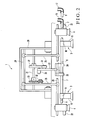
- a feed apparatus 1 for a printing press comprises first sucker devices 3 each of which chucks sheets 2 stacked on a pile board one by one from the uppermost one, second sucker devices 4 each of which chucks the sheet 2 transferred from the corresponding sucker device 3 and conveys it, a leveling foot 5 which enters between the first sheet chucked by the sucker device 3 and a sheet (second sheet) under the first sheet, holds the second sheet, and supplies air to separate the first sheet from the second sheet, and an air blower 6 which supplies air to the side surfaces of the sheets 2 so that the sheets 2 stacked on the pile board can be separated well.
- each sucker device 3 comprises an almost cylindrical guide nozzle 10, a blind cylindrical sucker 11 which fits on the outer surface of the guide nozzle 10 and is supported slidably and vertically movable, and a compression coil spring 12 which biases the sucker 11 downward with respect to the guide nozzle 10.
- a lower end 10a of the guide nozzle 10 forms a circular truncated cone with a tapered distal end, as shown in Fig. 4 .
- the guide nozzle 10 has, at its central portion, a sheet drawing air passage 14 extending in the vertical direction and having an opening 14a at its lower end.
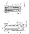
- the air passage 14 communicates with chuck holes 18a of the sucker 11 through the opening 14a, as shown in Fig. 3B .
- an air pipe 7 extends through the upper portion of the pair of guide nozzle 10, and the air pipe 7 is axially mounted on the guide nozzle 10.
- the upper end of the air passage 14 communicates with the air pipe 7.
- the air pipe 7 is connected to a hose 15 which is connected to an intake pump and exhaust pump (neither is shown) through rotary valves.
- the guide nozzle 10 has a cylindrical space around the air passage 14.
- the cylindrical space constitutes a sucker drawing air passage 16 in which the compression coil spring 12 is loaded.
- the air passage 16 has an exhaust port 16a having an opening at its lower end and exposed to the internal space of the sucker 11.
- the air passage 16 communicates with the chuck holes 18a through the exhaust port 16a.
- the upper end of the air passage 16 communicates with an air pipe 8 extending through the guide nozzle 10.
- the air pipe 8 is connected to a hose 17 connected to an intake pump (not shown) through a rotary valve (not shown).
- the sucker 11 has a plurality of chuck holes 18a in a bottom 18.
- the inner circumferential edge of the upper end of each chuck hole 18a forms an inverted cone.
- the chuck holes 18a constitute a valve seat 19 serving as a closing portion. Namely, when the valve seat 19 comes into contact with the lower end 10a of the guide nozzle 10, it closes the exhaust port 16a of the air passage 16; when it separates from the lower end 10a of the guide nozzle 10, it opens the exhaust port 16a of the air passage 16.
- the lower end 10a of the guide nozzle 10 constitutes a valve body with respect to the valve seat 19.
- valve seat 19 closes the exhaust port 16a of the air passage 16.
- a ring-shaped spring bearing 19a forms a recess at the upper edge of the valve seat 19 to surround the valve seat 19.
- the compression coil spring 12 loaded in the air passage 16 of the guide nozzle 10 is elastically mounted between the spring bearing 19a and the upper end of the air passage 16.
- a gap that does not interfere with the flow of air drawn from the air pipe 8 is reserved between the air passage 16 loaded with the compression coil spring 12 and the compression coil spring 12.
- the air passage 14 is formed at the central portion of the guide nozzle 10, and the air passage 16 loaded with the compression coil spring 12 is formed to surround the air passage 14.
- the structure of the guide nozzle 10 can be simplified and down-sized.
- a sucker frame 20 provided above the sheets 2 stacked on the pile board projects backward from the upper end of a sheet feed frame.
- a cam 22 for the pair of sucker device 3 and a cam 23 for the sucker devices 4 are axially mounted on a cam shaft 21 which is axially supported by the sucker frame 20.
- the guide nozzles 10 of the pair of sucker devices 3 are pivotally mounted on the lower end of the sucker frame 20 through adjusting devices (not shown) such that the angles of inclination of the guide nozzles 10 are adjustable.
- a pair of arms 25 vertically hang downward from an arm shaft 24 axially supported by the sucker frame 20.
- the arms 25 support a support shaft 26 horizontally, and the pair of sucker devices 4 are fixed at the two ends of the support shaft 26.
- a cam lever 27 is pivotally mounted on a bracket 28 fixed to the sheet feed frame, and a pair of levers 29 which support the air pipe 7 are pivotally attached to a pin 9 formed at the free end of the cam lever 27.
- a cam follower 31 is pivotally mounted at the center of the cam lever 27. As shown in Fig. 1 , the tensile force of a tension coil spring 32 brings the cam follower 31 into tight contact with the cam surface of the cam 22.
- a cam follower 32 is pivotally mounted on one of the pair of arms 25.
- a spring member (not shown) brings the cam follower 32 into tight contact with the cam surface of the cam 23.
- the sucker devices 4 reciprocate once per turn of the cam 23 between the position indicated by a solid line and the position indicated by an alternate long and two dashed line in Fig. 1 .
- the sucker devices 4 are connected to a hose 33 connected to an intake pump through a rotary valve (neither is shown).
- a pair of upper and lower feed rollers 34 and 35 are arranged at the front end of the feed apparatus.
- the rollers 34 and 35 capture the sheet 2 released from the sucker devices 4 and feed it onto a feeder board (not shown).
- the interiors of the sucker devices 3 are set in the negative pressure state.
- the external atmospheric pressure compresses the compression coil springs 12 in the guide nozzles 10, and the suckers 11 move upward, while chucking the sheet 2, due to the tensile operation of the compression coil springs 12.
- the valve seats 19 of the suckers 11 close the exhaust ports 16a of the air passages 16.
- the interiors of the air passages 16 are set in the negative pressure state.
- the suckers 11 are maintained at the upper limit.
- a small-diameter portion 22b of the cam 22 comes into contact with the cam follower 31 to move the cam lever 27 upward, as shown in Fig. 1 , so that the sucker devices 3 move upward together with the suckers 11, to return to the position indicated by a solid line.
- the leveling foot 5 enters and reliably presses the sheets so that air discharged from the leveling foot 5 does not cause the sheets from the second sheet to move upward to follow the first sheet.
- the suckers 11 of the sucker devices 3 are maintained at the upper limit and do not move downward, and accordingly will not come into contact with the sheet 2 chucked by the sucker devices 4.
- the sheet 2 will not be scratched, or will be separated from the sucker devices 4.
- the leveling foot 5 reliably holds the second and subsequent sheets, and air is reliably discharged to the gap between the first and second sheets.
- the sheets 2 can be reliably supplied one by one.
- the cam 23 and cam follower 32 swing the arms 25.
- the sucker devices 4 that chuck the sheet 2 move forward from the position indicated by the solid line to the position indicated by the alternate long and two short dashed line in Fig. 1 , and the feed rollers 34 and 35 capture the leading edge of the sheet 2.
- Figs. 6A and 6B show the second embodiment of the present invention.
- a lower end 10a of each guide nozzle 10 is formed flat, and a valve seat 19 of a bottom 18 of a sucker 11 which is in contact with the lower end 10a is also formed flat.
- the lower end 10a of the guide nozzle 10 and the valve seat 19 are formed of horizontal planes parallel to each other.
- the timing to start air drawing into the air passages 16 is set at the time T1 in the above embodiment, it may be at any time between the time 1 when air drawing into the air passages 14 is started and the time T3 when air drawing is stopped.
- the timing to end air drawing into the air passages 16 is set at the time T4, it may be before the time T4 as far as it is a timing at which the sheet 2 conveyed by the sucker devices 4 is not located below the sucker devices 3.
- the present invention when transferring the sheet from the first sucker devices to the second sucker devices, although air drawing for the sheet is stopped, air drawing into the air passages is continued. Therefore, before the suckers of the first sucker devices move downward, the second sucker devices can convey the sheet. According to the present invention, the sheet can be prevented from being scratched by the suckers of the first sucker devices or from separated from the second sucker devices.
Landscapes
- Engineering & Computer Science (AREA)
- Mechanical Engineering (AREA)
- Sheets, Magazines, And Separation Thereof (AREA)
Applications Claiming Priority (1)
| Application Number | Priority Date | Filing Date | Title |
|---|---|---|---|
| JP2007207645A JP5004714B2 (ja) | 2007-08-09 | 2007-08-09 | 印刷機の給紙装置 |
Publications (3)
| Publication Number | Publication Date |
|---|---|
| EP2033916A2 true EP2033916A2 (de) | 2009-03-11 |
| EP2033916A3 EP2033916A3 (de) | 2011-06-15 |
| EP2033916B1 EP2033916B1 (de) | 2012-10-17 |
Family
ID=40278997
Family Applications (1)
| Application Number | Title | Priority Date | Filing Date |
|---|---|---|---|
| EP08013938A Not-in-force EP2033916B1 (de) | 2007-08-09 | 2008-08-04 | Zufuhrvorrichtung für eine Druckpresse |
Country Status (4)
| Country | Link |
|---|---|
| US (1) | US7926802B2 (de) |
| EP (1) | EP2033916B1 (de) |
| JP (1) | JP5004714B2 (de) |
| CN (1) | CN101362559B (de) |
Families Citing this family (5)
| Publication number | Priority date | Publication date | Assignee | Title |
|---|---|---|---|---|
| WO2016141462A1 (en) * | 2015-03-06 | 2016-09-15 | Premier Tech Technologies Ltée | Apparatus and method for repeatedly separating and displacing a topmost bag of a stack of bags |
| DE102015112625A1 (de) * | 2015-07-31 | 2017-02-16 | Hanses Sägewerkstechnik GmbH & Co. KG | Verfahren zum Abstapeln von Furnierblättern |
| CN108438965B (zh) * | 2018-04-25 | 2020-04-24 | 江苏三和生物工程股份有限公司 | 一种便于取用的止血膜储存装置 |
| DE102023103826B3 (de) * | 2023-02-16 | 2023-12-28 | Heidelberger Druckmaschinen Aktiengesellschaft | Hubsauger-Steuerverfahren |
| CN119056835A (zh) * | 2024-08-26 | 2024-12-03 | 江苏路芯半导体技术有限公司 | 一种掩膜板夹具及防死角式清洗装置 |
Citations (2)
| Publication number | Priority date | Publication date | Assignee | Title |
|---|---|---|---|---|
| DE3644201A1 (de) | 1986-12-23 | 1988-07-07 | Mabeg Maschinenbau Gmbh Nachf | Pneumatische vorrichtung |
| US5064184A (en) | 1989-04-14 | 1991-11-12 | Georg Spiess Gmbh | Feeder |
Family Cites Families (20)
| Publication number | Priority date | Publication date | Assignee | Title |
|---|---|---|---|---|
| US1442718A (en) * | 1920-03-04 | 1923-01-16 | Jones & Laughlin Steel Company | Conveyer |
| US2247473A (en) * | 1940-07-12 | 1941-07-01 | Dexter Folder Co | Sheet feeding apparatus |
| US3071371A (en) * | 1960-12-07 | 1963-01-01 | Miehle Goss Dexter Inc | Sheet feeding apparatus |
| FR2195753B1 (de) * | 1972-08-11 | 1975-03-07 | Carnaud & Forges | |
| US3931964A (en) * | 1973-02-23 | 1976-01-13 | Mabeg Maschinenbau Gmbh | Sheet feeder apparatus |
| US3937457A (en) * | 1974-05-14 | 1976-02-10 | Mabeg Maschinenbau Gmbh | Sheet feeder apparatus |
| US4327906A (en) * | 1978-05-02 | 1982-05-04 | Stahl Gmbh & Co. | Sheet separating apparatus |
| US4438916A (en) * | 1981-03-04 | 1984-03-27 | Komori Printing Machinery Co., Ltd. | Paper feeder |
| US4458891A (en) * | 1981-03-04 | 1984-07-10 | Komori Printing Machinery Co., Ltd. | Paper feeder |
| JPS58125539A (ja) * | 1982-01-18 | 1983-07-26 | Mitsubishi Heavy Ind Ltd | 吸着装置 |
| DE3508736A1 (de) * | 1985-03-12 | 1986-09-25 | Fraunhofer-Gesellschaft zur Förderung der angewandten Forschung e.V., 8000 München | Vorrichtung zum vereinzeln und zum transport des jeweils obersten blattes eines stapels von blaettern oder blattfoermigen gegenstaenden |
| JPS6376739U (de) * | 1986-11-07 | 1988-05-21 | ||
| DE3710994A1 (de) * | 1987-04-01 | 1988-10-13 | Heidelberger Druckmasch Ag | Saugkopf mit hubsaugern |
| DE3743805C1 (de) * | 1987-12-23 | 1989-06-01 | Heidelberger Druckmasch Ag | Trennsaugereinrichtung fuer einen Anleger einer Druckmaschine |
| DD278566A1 (de) * | 1988-12-27 | 1990-05-09 | Polygraph Leipzig | Vorrichtung zum vereinzeln und foerdern von gestapelten bogen |
| JP2524972Y2 (ja) | 1989-07-12 | 1997-02-05 | 株式会社岡村製作所 | パネル同士の側方連結装置 |
| JP2568437Y2 (ja) * | 1992-09-03 | 1998-04-15 | 株式会社小森コーポレーション | 給紙用吸着装置 |
| DE4234184C2 (de) * | 1992-10-10 | 1996-02-01 | Heidelberger Druckmasch Ag | Hubsauger zum Anheben eines Papierbogens vom Stapel und zum Halten des Bogens in der angehobenen Position oberhalb des Stapels |
| GB2377707B (en) * | 2001-04-26 | 2004-10-20 | Thk Co Ltd | Microarraying head and microarrayer |
| JP4673546B2 (ja) * | 2002-10-25 | 2011-04-20 | ハイデルベルガー ドルツクマシーネン アクチエンゲゼルシヤフト | 跳上げ式吸い口 |
-
2007
- 2007-08-09 JP JP2007207645A patent/JP5004714B2/ja not_active Expired - Fee Related
-
2008
- 2008-08-04 EP EP08013938A patent/EP2033916B1/de not_active Not-in-force
- 2008-08-04 US US12/221,531 patent/US7926802B2/en not_active Expired - Fee Related
- 2008-08-07 CN CN2008101296996A patent/CN101362559B/zh not_active Expired - Fee Related
Patent Citations (2)
| Publication number | Priority date | Publication date | Assignee | Title |
|---|---|---|---|---|
| DE3644201A1 (de) | 1986-12-23 | 1988-07-07 | Mabeg Maschinenbau Gmbh Nachf | Pneumatische vorrichtung |
| US5064184A (en) | 1989-04-14 | 1991-11-12 | Georg Spiess Gmbh | Feeder |
Also Published As
| Publication number | Publication date |
|---|---|
| EP2033916B1 (de) | 2012-10-17 |
| JP5004714B2 (ja) | 2012-08-22 |
| CN101362559B (zh) | 2012-07-18 |
| US7926802B2 (en) | 2011-04-19 |
| EP2033916A3 (de) | 2011-06-15 |
| JP2009040552A (ja) | 2009-02-26 |
| US20090039589A1 (en) | 2009-02-12 |
| CN101362559A (zh) | 2009-02-11 |
Similar Documents
| Publication | Publication Date | Title |
|---|---|---|
| US7926802B2 (en) | Feed apparatus for printing press | |
| JP3862973B2 (ja) | 極板積層体の極板分離供給装置 | |
| US7600748B2 (en) | Sheet feeding device with concave suction belt | |
| US20060170146A1 (en) | Sheet convey apparatus | |
| CN208008109U (zh) | 飞达压脚机构 | |
| US6629692B2 (en) | Device for separating an uppermost sheet from a supply stack by means of air blowers | |
| JP2015158274A (ja) | ニューマチック式に制御可能な吸盤を備えた持上げ用サッカ | |
| JP2001179938A (ja) | 枚葉紙を個別化して搬送する方法および装置 | |
| JP2568437Y2 (ja) | 給紙用吸着装置 | |
| JP4802865B2 (ja) | 筒状ラベル嵌装装置 | |
| CA2612676A1 (en) | Fuel feed system of engine | |
| JP2004142949A (ja) | 跳上げ式吸い口 | |
| JP4691534B2 (ja) | 枚葉印刷機の給紙部のサッカー装置 | |
| KR100758129B1 (ko) | 인서트부재의 전달장치 및 그 방법 | |
| US2874962A (en) | Sheet feeding system for printing presses and the like | |
| EP1746058B1 (de) | Pendelzuführeinrichtung für Briefumschläge mit Saugnapf und entsprechendes Verfahren | |
| JPS6246451B2 (de) | ||
| JP2006007594A (ja) | 印刷機 | |
| TW404887B (en) | Front-sucking and top-dispatching paper feeding device | |
| JP2001252732A (ja) | 2枚分離兼用のブランク材保持装置 | |
| JP2553005Y2 (ja) | 給紙用吸着装置 | |
| SU335168A1 (ru) | УСТРОЙСТВО дл ПОШТУЧНОЙ ВЫДАЧИ БУМАЖНЫХЗАГОТОВОК из стопы | |
| JP6814566B2 (ja) | 印刷装置 | |
| KR200429320Y1 (ko) | 인서트부재의 전달장치 | |
| JP5576916B2 (ja) | 被供給材の供給装置 |
Legal Events
| Date | Code | Title | Description |
|---|---|---|---|
| PUAI | Public reference made under article 153(3) epc to a published international application that has entered the european phase |
Free format text: ORIGINAL CODE: 0009012 |
|
| AK | Designated contracting states |
Kind code of ref document: A2 Designated state(s): AT BE BG CH CY CZ DE DK EE ES FI FR GB GR HR HU IE IS IT LI LT LU LV MC MT NL NO PL PT RO SE SI SK TR |
|
| AX | Request for extension of the european patent |
Extension state: AL BA MK RS |
|
| PUAL | Search report despatched |
Free format text: ORIGINAL CODE: 0009013 |
|
| AK | Designated contracting states |
Kind code of ref document: A3 Designated state(s): AT BE BG CH CY CZ DE DK EE ES FI FR GB GR HR HU IE IS IT LI LT LU LV MC MT NL NO PL PT RO SE SI SK TR |
|
| AX | Request for extension of the european patent |
Extension state: AL BA MK RS |
|
| 17P | Request for examination filed |
Effective date: 20111205 |
|
| AKX | Designation fees paid |
Designated state(s): CH DE FR GB LI NL |
|
| GRAP | Despatch of communication of intention to grant a patent |
Free format text: ORIGINAL CODE: EPIDOSNIGR1 |
|
| GRAS | Grant fee paid |
Free format text: ORIGINAL CODE: EPIDOSNIGR3 |
|
| GRAA | (expected) grant |
Free format text: ORIGINAL CODE: 0009210 |
|
| AK | Designated contracting states |
Kind code of ref document: B1 Designated state(s): CH DE FR GB LI NL |
|
| REG | Reference to a national code |
Ref country code: GB Ref legal event code: FG4D |
|
| REG | Reference to a national code |
Ref country code: CH Ref legal event code: EP |
|
| REG | Reference to a national code |
Ref country code: NL Ref legal event code: T3 |
|
| REG | Reference to a national code |
Ref country code: DE Ref legal event code: R096 Ref document number: 602008019377 Country of ref document: DE Effective date: 20121213 |
|
| PLBE | No opposition filed within time limit |
Free format text: ORIGINAL CODE: 0009261 |
|
| STAA | Information on the status of an ep patent application or granted ep patent |
Free format text: STATUS: NO OPPOSITION FILED WITHIN TIME LIMIT |
|
| 26N | No opposition filed |
Effective date: 20130718 |
|
| PGFP | Annual fee paid to national office [announced via postgrant information from national office to epo] |
Ref country code: NL Payment date: 20130815 Year of fee payment: 6 Ref country code: CH Payment date: 20130828 Year of fee payment: 6 |
|
| REG | Reference to a national code |
Ref country code: DE Ref legal event code: R097 Ref document number: 602008019377 Country of ref document: DE Effective date: 20130718 |
|
| PGFP | Annual fee paid to national office [announced via postgrant information from national office to epo] |
Ref country code: GB Payment date: 20130715 Year of fee payment: 6 Ref country code: FR Payment date: 20130812 Year of fee payment: 6 |
|
| REG | Reference to a national code |
Ref country code: NL Ref legal event code: V1 Effective date: 20150301 |
|
| REG | Reference to a national code |
Ref country code: CH Ref legal event code: PL |
|
| GBPC | Gb: european patent ceased through non-payment of renewal fee |
Effective date: 20140804 |
|
| PG25 | Lapsed in a contracting state [announced via postgrant information from national office to epo] |
Ref country code: NL Free format text: LAPSE BECAUSE OF NON-PAYMENT OF DUE FEES Effective date: 20150301 Ref country code: LI Free format text: LAPSE BECAUSE OF NON-PAYMENT OF DUE FEES Effective date: 20140831 Ref country code: CH Free format text: LAPSE BECAUSE OF NON-PAYMENT OF DUE FEES Effective date: 20140831 |
|
| REG | Reference to a national code |
Ref country code: FR Ref legal event code: ST Effective date: 20150430 |
|
| PG25 | Lapsed in a contracting state [announced via postgrant information from national office to epo] |
Ref country code: GB Free format text: LAPSE BECAUSE OF NON-PAYMENT OF DUE FEES Effective date: 20140804 |
|
| PG25 | Lapsed in a contracting state [announced via postgrant information from national office to epo] |
Ref country code: FR Free format text: LAPSE BECAUSE OF NON-PAYMENT OF DUE FEES Effective date: 20140901 |
|
| PGFP | Annual fee paid to national office [announced via postgrant information from national office to epo] |
Ref country code: DE Payment date: 20171102 Year of fee payment: 10 |
|
| REG | Reference to a national code |
Ref country code: DE Ref legal event code: R119 Ref document number: 602008019377 Country of ref document: DE |
|
| PG25 | Lapsed in a contracting state [announced via postgrant information from national office to epo] |
Ref country code: DE Free format text: LAPSE BECAUSE OF NON-PAYMENT OF DUE FEES Effective date: 20190301 |