EP2029950B1 - Convection combustion oven - Google Patents
Convection combustion oven Download PDFInfo
- Publication number
- EP2029950B1 EP2029950B1 EP07726014A EP07726014A EP2029950B1 EP 2029950 B1 EP2029950 B1 EP 2029950B1 EP 07726014 A EP07726014 A EP 07726014A EP 07726014 A EP07726014 A EP 07726014A EP 2029950 B1 EP2029950 B1 EP 2029950B1
- Authority
- EP
- European Patent Office
- Prior art keywords
- pressurized air
- air
- oven housing
- oven
- set forth
- Prior art date
- Legal status (The legal status is an assumption and is not a legal conclusion. Google has not performed a legal analysis and makes no representation as to the accuracy of the status listed.)
- Active
Links
Images


Classifications
-
- F—MECHANICAL ENGINEERING; LIGHTING; HEATING; WEAPONS; BLASTING
- F27—FURNACES; KILNS; OVENS; RETORTS
- F27B—FURNACES, KILNS, OVENS OR RETORTS IN GENERAL; OPEN SINTERING OR LIKE APPARATUS
- F27B9/00—Furnaces through which the charge is moved mechanically, e.g. of tunnel type; Similar furnaces in which the charge moves by gravity
- F27B9/06—Furnaces through which the charge is moved mechanically, e.g. of tunnel type; Similar furnaces in which the charge moves by gravity heated without contact between combustion gases and charge; electrically heated
- F27B9/10—Furnaces through which the charge is moved mechanically, e.g. of tunnel type; Similar furnaces in which the charge moves by gravity heated without contact between combustion gases and charge; electrically heated heated by hot air or gas
-
- B—PERFORMING OPERATIONS; TRANSPORTING
- B05—SPRAYING OR ATOMISING IN GENERAL; APPLYING FLUENT MATERIALS TO SURFACES, IN GENERAL
- B05D—PROCESSES FOR APPLYING FLUENT MATERIALS TO SURFACES, IN GENERAL
- B05D3/00—Pretreatment of surfaces to which liquids or other fluent materials are to be applied; After-treatment of applied coatings, e.g. intermediate treating of an applied coating preparatory to subsequent applications of liquids or other fluent materials
- B05D3/02—Pretreatment of surfaces to which liquids or other fluent materials are to be applied; After-treatment of applied coatings, e.g. intermediate treating of an applied coating preparatory to subsequent applications of liquids or other fluent materials by baking
- B05D3/0254—After-treatment
-
- B—PERFORMING OPERATIONS; TRANSPORTING
- B05—SPRAYING OR ATOMISING IN GENERAL; APPLYING FLUENT MATERIALS TO SURFACES, IN GENERAL
- B05D—PROCESSES FOR APPLYING FLUENT MATERIALS TO SURFACES, IN GENERAL
- B05D3/00—Pretreatment of surfaces to which liquids or other fluent materials are to be applied; After-treatment of applied coatings, e.g. intermediate treating of an applied coating preparatory to subsequent applications of liquids or other fluent materials
- B05D3/04—Pretreatment of surfaces to which liquids or other fluent materials are to be applied; After-treatment of applied coatings, e.g. intermediate treating of an applied coating preparatory to subsequent applications of liquids or other fluent materials by exposure to gases
- B05D3/0406—Pretreatment of surfaces to which liquids or other fluent materials are to be applied; After-treatment of applied coatings, e.g. intermediate treating of an applied coating preparatory to subsequent applications of liquids or other fluent materials by exposure to gases the gas being air
- B05D3/0413—Heating with air
-
- F—MECHANICAL ENGINEERING; LIGHTING; HEATING; WEAPONS; BLASTING
- F26—DRYING
- F26B—DRYING SOLID MATERIALS OR OBJECTS BY REMOVING LIQUID THEREFROM
- F26B21/00—Arrangements or duct systems, e.g. in combination with pallet boxes, for supplying and controlling air or gases for drying solid materials or objects
- F26B21/004—Nozzle assemblies; Air knives; Air distributors; Blow boxes
-
- F—MECHANICAL ENGINEERING; LIGHTING; HEATING; WEAPONS; BLASTING
- F26—DRYING
- F26B—DRYING SOLID MATERIALS OR OBJECTS BY REMOVING LIQUID THEREFROM
- F26B23/00—Heating arrangements
- F26B23/02—Heating arrangements using combustion heating
-
- F—MECHANICAL ENGINEERING; LIGHTING; HEATING; WEAPONS; BLASTING
- F27—FURNACES; KILNS; OVENS; RETORTS
- F27B—FURNACES, KILNS, OVENS OR RETORTS IN GENERAL; OPEN SINTERING OR LIKE APPARATUS
- F27B9/00—Furnaces through which the charge is moved mechanically, e.g. of tunnel type; Similar furnaces in which the charge moves by gravity
- F27B9/30—Details, accessories or equipment specially adapted for furnaces of these types
- F27B9/36—Arrangements of heating devices
-
- B—PERFORMING OPERATIONS; TRANSPORTING
- B05—SPRAYING OR ATOMISING IN GENERAL; APPLYING FLUENT MATERIALS TO SURFACES, IN GENERAL
- B05D—PROCESSES FOR APPLYING FLUENT MATERIALS TO SURFACES, IN GENERAL
- B05D7/00—Processes, other than flocking, specially adapted for applying liquids or other fluent materials to particular surfaces or for applying particular liquids or other fluent materials
- B05D7/14—Processes, other than flocking, specially adapted for applying liquids or other fluent materials to particular surfaces or for applying particular liquids or other fluent materials to metal, e.g. car bodies
-
- F—MECHANICAL ENGINEERING; LIGHTING; HEATING; WEAPONS; BLASTING
- F26—DRYING
- F26B—DRYING SOLID MATERIALS OR OBJECTS BY REMOVING LIQUID THEREFROM
- F26B2210/00—Drying processes and machines for solid objects characterised by the specific requirements of the drying good
- F26B2210/12—Vehicle bodies, e.g. after being painted
Definitions
- the present invention relates toward an inventive oven for curing coatings applied to an object. More specifically, the present invention relates to a convection combustion oven having a simplified design for curing coatings applied to an object.
- ovens are used to cure coatings, such as, for example, paint and sealers, that are applied to articles in a production setting.
- coatings such as, for example, paint and sealers
- One example is decorative and protective paint that is applied to automotive vehicle bodies in a high volume paint shop known to process vehicle bodies at rates exceeding one per minute.
- a typical oven uses combustion fuel to provide the necessary amount of heat to cure paint applied to a vehicle body.
- a convection oven makes use of a heat source such as natural gas flame that heats pressurized air prior to delivering the heated air to an oven housing.
- a first type of convection heating applies combustion heat directly to pressurized air prior to delivery to the oven housing mixing combustion gases with the pressurized air.
- a second type of convection heating uses an indirect heating process where combustion heat is directed into a heat exchanger that heats the pressurized air without mixing the combustion gases with the pressurized air.
- a radiant heater that transfers heat to the vehicle body by way of proximity to the vehicle body.
- a radiant heater is generally a metal panel that is heated by circulating hot air into a space located behind a radiator.
- a conventional oven design is generally shown at 10 in Figure 1 .
- the conventional oven assembly 10 generally includes two main components, a heater box 12 and an oven housing 14.
- the heater box 12 is generally spaced from the oven housing 14 and includes components (not shown) to provide heat and pressurized air to the oven housing 14 through hot air duct 16.
- the heater box 12 includes a return duct that draws a significant portion of air from the interior of the oven housing 14 for recirculation through the oven housing 14. Up to ninety percent of the air passing through the heater box 12 is derived from the interior of the oven housing 14 through return duct 16.
- Hot air is directed through hot air headers 20 toward the vehicle body through nozzles 22 to optimize a uniform heat transfer to cure the coating applied to the vehicle body.
- the vehicle body is heated to about 275-340° F (135-171°C) at a predetermined time to adequately cure the applied coating.
- Some coatings, such as electrodeposition primers, require temperatures at the higher end of this range. As is known to those of skill in the art, more heat must be directed toward heavy metal areas of the vehicle body to derive the desired baking temperature.
- a typical oven zone of about eighty feet (24 m) in length of a conventional oven requires an actual air volume of about 30,000 cfm (51,000 m 3 /h) when using a heater box. This high air volume is required to transfer the necessary heat to the vehicle body to cure the applied coating.
- the air temperature at the nozzle 22 in a conventional oven is generally 444° F (229°C) requiring an air velocity at the nozzle 22 of 4,930 fpm (25 m/s) to transfer the desired amount of heat energy.
- the operating parameter set forth above generally provides 1,595,000 BTU/hr (468 kW) at a momentum of 4.9 x 10 6 ft-lb/sec (680 kN ⁇ s). Because hot air is recirculated by the fan located in the heater box 12, and because the recirculated air is often reheated prior to being pressurized by the fan, the fan requires an overlying robust design adding to operation and installation costs.
- US-A-2004/0076919 discloses an apparatus for curing paint on a surface of a vehicle body comprising an oven enclosure having at least one oven section for receiving a vehicle body; a plurality of radiant tube heating elements disposed in said at least one oven section; an oven heater having at least one burner, said oven heater being positioned external to said at least one oven section and connected to said heating elements for providing heat energy to said at least one oven section; and a plurality of supply conduits that are connected to a supply of heated fresh air and supply heated fresh air to the oven interior during operation of the apparatus for curing paint.
- US-A-2005/087183 discloses an oven assembly according to the preamble portion of claim 1.
- the present invention discloses an oven assembly for curing a coating applied to an article being conveyed through the oven assembly.
- a transporter extends through an oven housing for conveying the article through the oven assembly.
- a fan provides pressurized air into the oven housing drawn substantially from outside the oven housing.
- a duct includes a first element extending into the oven housing and a second element interconnected with the fan for transporting pressurized air from the fan into the oven housing.
- a burner is disposed generally between the first element and the second element for heating the pressurized air being transported into the oven housing.
- the first element defines a plurality of air outlets spaced throughout the oven housing for directing heated air toward the article.
- the first element is substantially insulated inside the oven housing reducing the escape of heat generated by the burner from the duct except through the air outlet. The burner heats the pressurized air being directed into the oven housing to a temperature of about three times the curing temperature of the coating that is applied to the article.
- the inventive oven assembly solves the problems associated with the prior art, or conventional oven assembly.
- the size of the ventilator or fan used to provide pressurized air to the oven housing for transferring heat to the article being baked is significantly reduced for two reasons.
- the fan primarily draws ambient temperature air as the present design does not circulate heated air back into the oven housing and, therefore, does not need to be heat resistant.
- the heater or burner used to heat the ambient temperature air prior to the introduction to the first element of the duct is configured to heat the air to about two to four times the curing temperature of the coating applied to the vehicle body adjacent the oven housing.
- This temperature air when introduced to the oven interior at a high nozzle velocity, reduces the air volume of a conventional 80 foot (24 m) long oven zone from about 30,000 acfm (51,000 m 3 /h) to about 2,000 scfm (3,400 m 3 N/ h).
- a substantially similar amount of BTUs per hour is delivered to the oven as a conventional oven while using less energy to drive the ventilator and having a significantly simplified ventilation and heating apparatus.
- the complex heater box presently used in conventional ovens is no longer necessary and is, therefore, completely eliminated substantially simplifying the construction and design of a production oven.
- the oven assembly includes an oven housing 32 through which an article such as, for example, a vehicle body 34 is conveyed on a transporter 36.
- the transporter 36 as is known to those of skill in the art, is generally designed as a conveyor that conveys a carrier 38 upon which the vehicle body 34 is secured.
- a coating is applied to the vehicle body 34 providing decorative and protective paint finish to the vehicle body 34.
- Different coatings have different baking or curing requirements that, along with vehicle body type and production volume, dictate the length and thermal requirements of the inventive oven assembly 30.
- electrodeposition primers typically cure at about 340° F (170°C) for about twenty minutes and decorative top coat and clear coats cure at about 285° F (140°C) also for about twenty minutes.
- the explanation of the inventive concepts of the present oven assembly 30 will assume a typical eighty foot (24 m) long oven zone requiring a delivery of heat of about 1,595,000 British thermal minutes per hour (BTU/hr) (468 kW).
- Pressurized air is delivered into the oven housing 32 through a duct 40 by a ventilator 42.
- the ventilator 42 is a conventional fan capable of providing the transfer of ambient air at a volume of about 2,000 scfm (3,400 m 3 N /h).
- the duct 40 includes a first element 44 generally extending inside the oven housing 32 and a second element 46 generally extending from the ventilator 42 to the first element 44.
- a heater 48 is disposed between the first element 44 and the second element 46 to provide heat to the pressurized air passing through the duct 40 as delivered by the ventilator 42.
- the heater 48 is a gas fired burner sized to provide the desired amount of heat to the pressurized air passing through the duct 40 to adequately cure the coating applied to the vehicle body 34.
- alternative heaters may also be used to provide heat to the pressurized air as set forth above.
- the heater increases the temperature of the pressurized air to about 1,100° F (593°C) or hotter.
- One range contemplated is between about 700° and 1,100° F (371° and 593°C).
- the desired temperature in Fahrenheit degrees) is selected to be between about two and four times the curing temperature of the coating (in Fahrenheit degrees) as will be explained further below.
- the heater is located, preferably, adjacent to or nearly adjacent to the oven housing 32 so that the heated, pressurized air travels only through the interior of the oven housing 32. This reduces the need to insulate the duct 40, or more specifically, the second element 46 of the duct 40 further reducing assembly costs.
- insulation 50 covers the first element 44 of the duct 40 inside the oven housing 32 to prevent the escape of heat through the first element 44 into the oven housing 32 except where desired.
- the oven assembly 30 represented in Figure 2 shows two heaters 48 positioned on opposing sides of the oven housing 32, each providing heat to opposing first elements 44. Therefore, the first element 44 of the duct 40 is disposed on opposing sides of the vehicle body 34 being transported through the oven housing 32. However, it should be understood that a single heater 48 is contemplated to provide heat to each of the opposing first elements 44 of the duct 40 by locating the heater 48 generally midway between each of the opposing first elements 44.
- Each first element 44 defines an upper header 52 and a lower header 54 that extend in a generally horizontal direction.
- Nozzles 56 are spaced along each of the upper header 52 and lower header 54 through which pressurized, heated air is projected toward predetermined locations on the vehicle body 34.
- Figure 3 best represents the spaced locations of the nozzles 56 on the upper header 52 and lower header 54, the configuration of which will be explained further below.
- a feed header 58 extends between the heater 48 and the lower header 54 of the first element 44.
- the feed header 58 serves as a mixer providing distance between the first of the nozzles 56 and the heater 48 so that the combustion gases produced by the heater 48 have ample time to mix with the pressurized air provided by the ventilator 42.
- the first element 44 shown in Figure 3 shows in connection serially, the feed header 58 with the lower header 54, which is connected to the upper header 52 by a connection header 60.
- the pressurized air travels a single path through the feed header 58 to the lower header 54, through the connection header 60, terminating at a distal end 62 of the upper header 52.
- a heater 48 placed in a lower portion of the oven assembly 30 connects first to the upper header 52 via feed header 58 reversing the direction of the pressurized air through the first element 44.
- vertical temperature probes 68 extend downwardly from the roof of the oven housing 32 to measure the interior temperature of the oven housing 32.
- the vertical temperature probes 68 communicate with a controller (not shown) that signals the heaters 48 to adjust, when necessary, the interior temperature of the oven housing 32.
- Horizontal temperature probes 70 are spaced below the vertical temperature probes 68 and measure temperature in a similar manner as the vertical temperature probes 68 the temperature of the oven in the lower regions of the housing 32.
- Header temperature probes 72 extend into the feed header 58 to measure the temperature of the pressurized air inside the feed header 58 in a manner similar to that explained for the vertical temperature probe 68 above. Each of the probes interact with the controller to control the temperature of the interior of the oven housing 32. Additional header temperature probes 72 may be spaced along the second element 46 if necessary.
- vertical or horizontal probes 68,70 may be located directly in front of a nozzle 56, spaced from the nozzle 56 between one to three feet.
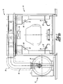
- FIG. 4 a cross-sectional view of one of the upper header 52 and lower header 54 is shown.
- insulation 50 surrounds a header wall 74 reducing the heat loss through the header wall 74 into the oven housing 32.
- the nozzles 56 are located inside the header wall 74 and define a decreasing diameter from a distal end 76 toward a terminal end 78 located generally adjacent the header wall 74. Therefore, the nozzle 56 defines a generally concave, frustoconical shape so that the pressurized air passing through the nozzle 56 accelerates due to decreasing area upon exit from the first element 44.
- the shape of the nozzles 56 is best represented in the perspective view shown in Figure 5A.
- Figure 5B shows an alternative nozzle 57 having a swivel 80 that allows the alternative nozzle 57 to be articulated inside the first element 44 enabling the pressurized air to be directed to the predetermined location in a more accurate manner.
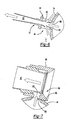
- FIG. 6 An alternative nozzle in the form of an eductor or venturi nozzle is shown at 82 in Figure 6 .
- the eductor 82 is shown in Figure 6 having a mating surface 86 that is affixed to header wall 74 outside of the header 52, 54.
- the mating surface 86 defines a pressurized air inlet 88 that receives pressurized air from one of the upper and lower header 52, 54.
- the pressurized air passes through venturi chamber 90 and exits the eductor 82 through eductor nozzle 92 directing the pressurized air toward the predetermined location of the vehicle body 34 as set forth above.
- Hot air is drawn from the interior of the oven housing 32 through venturi inlet 94 and is forced into the eductor nozzle 92 by the pressurized air passing through the venturi chamber 90 via venturi effect as is known. This increases the volumetric flow of air toward the predetermined location of the vehicle body 34 further reducing the energy requirements of the ventilator 42.
- a further embodiment nozzle is shown as an air amplifier 96 at Figure 7 where like numerals will be used with Figure 6 for simplicity.
- the air amplifier 96 includes an air inlet 88 where pressurized air is forced from one of the upper and lower headers 52, 54.
- the pressurized air passes through the venturi chamber 90 and into the amplifier nozzle 92 and directs the pressurized air toward a predetermined location of the vehicle body 34.
- Heated air is drawn from the interior of the oven housing 32 through venturi inlet 94 via the venturi effect causing an increase in the volumetric flow of heated air directed toward the vehicle body 34 again reducing the energy requirements of the ventilator 42.
- the embodiments set forth above are desirable to heat heavy metal areas of the vehicle body 34, which have higher heat requirements than thin or sheet metal areas of the vehicle body 34.
- the eductor 84 and the air amplifier 96 are each directed at a predetermined location of the vehicle body drawing heated air from inside the oven housing 32 maximizing the amount of heat energy directed toward the heavy metal area of the vehicle body 34.
- pressurized air passes through the header 52, 54 through air inlet 88 and into the venturi chamber 90 prior to exiting through the nozzle 92. Hot air is drawn into venturi inlet 94 via the venturi effect increasing the volumetric flow rate of hot air being directed toward the vehicle body 34.
- Table 1 shows the operational parameters of the inventive oven assembly 30 that provides the benefits set forth above.
- Table 1 Conventional Oven New Oven New Oven New Oven Nominal Design Nominal Design Low Velocity Case High Velocity Case Heat Delivered BTU/hr (kW) 1,595,217 (468) 1,595,217 (468) 1,595,217 (468) 1,595,217 (468) Volum Delivered ft lbm/sec (N ⁇ s) 1,365 (188) 1,365 (188) 836 (116) 1,643 (227) Delivery Volume - Actual acfm (m 3 /h) 30,000 (51,000) 6,000 (10,200) 6,000 (10,200) 6,000 (10,200) Delivery Volume - Standard scfm (m 3 N /h) 17,584 (30,000) 2,000 (3,400) 2,000 (3,400) 2,000 (3,400) 2,000 (3,400) Air Delivery Temperature F (°C) 444 (230) 1,100 (593) 1,100 (593) 1,100 (593)
- the data shown in Table 1 is based upon a typical 80 foot (24 m) long oven section (i.e., heat up zone) at a typical vehicle body 34 production rate. In each example, the required heat delivery is about 1,595,000 BTU/hr (468 kW).
- the first column shows the various operating requirements to produce the heat required in a conventional oven design and the following columns indicate the inventive oven nominal design, with a lower limit velocity and an upper limit velocity establishing the general operating range.
- the air delivery temperature at the nozzles 56 is increased to about 1,100° F (593°C) in the new oven design exceeding the conventional air delivery temperature at a conventional nozzle 22 of about 444° F (230°C).
- the nozzle diameter is reduced from a conventional diameter of about .38 feet (116 mm) to about .06 feet (18 mm) resulting in an increase in air velocity at the nozzle from 3,727 fpm (19 m/s) to about 32,000 fpm (163 m/s) in the nominal oven assembly 30.
- the ratio set forth above makes use of an air velocity to air volume ratio (in 1/ft 2 ) at the nozzles 56 of between about 150 and 650 to 1, with a nominal ratio of about 400 to 1 (an air velocity to air volume ratio (in 1/m 2 ) of between about 1,584 and 6,950 to 1, with a nominal ratio of about 4,300 to 1). Furthermore, the ratio of air velocity in feet per second to a nozzle area in square feet is determined to be between about 50,000 and 400,000 to 1, with a nominal velocity of about 220,000 to 1 (the ratio of air velocity in meters per second to a nozzle area in square meters is determined to be between about 165,000 and 1,330,000 to one, with a nominal velocity of about 640,000 to 1).
- Further operating parameters proven to achieve desired heat and momentum requirements include providing the volume of air to the oven housing at less than about 25 scfm per foot (139 m 3 N /h per meter) of oven housing.
- An alternate embodiment provides a volume of air to the oven housing of less than about 50 scfm per foot (278 m 3 N /h per meter) of oven housing.
- a still further alternate embodiment provides a volume of air to the oven housing at a rate of about 75 scfm per foot (417 m 3 N /h per meter) of oven housing. This is significantly less than a conventional oven design which requires about 220 scfm per foot (1227 m 3 N /h per meter) oven length, requiring higher energy usage than the inventive oven assembly 30.
- An additional benefit of heating the pressurized air to about 1,100° F (593°C) is the ability to clean the oven 30 by combustion of coating byproducts known to coat oven walls. This eliminates the need to manually wash oven walls, which is labor intensive.
Landscapes
- Engineering & Computer Science (AREA)
- Mechanical Engineering (AREA)
- General Engineering & Computer Science (AREA)
- Combustion & Propulsion (AREA)
- Chemical & Material Sciences (AREA)
- Life Sciences & Earth Sciences (AREA)
- Sustainable Development (AREA)
- Wood Science & Technology (AREA)
- Coating Apparatus (AREA)
- Drying Of Solid Materials (AREA)
- Application Of Or Painting With Fluid Materials (AREA)
- Furnace Details (AREA)
- Tunnel Furnaces (AREA)
- Acyclic And Carbocyclic Compounds In Medicinal Compositions (AREA)
- Nitrogen Condensed Heterocyclic Rings (AREA)
- Pharmaceuticals Containing Other Organic And Inorganic Compounds (AREA)
- Baking, Grill, Roasting (AREA)
Applications Claiming Priority (5)
| Application Number | Priority Date | Filing Date | Title |
|---|---|---|---|
| US81463206P | 2006-06-16 | 2006-06-16 | |
| US80787506P | 2006-07-20 | 2006-07-20 | |
| US83908206P | 2006-08-21 | 2006-08-21 | |
| US11/701,254 US7905723B2 (en) | 2006-06-16 | 2007-02-01 | Convection combustion oven |
| PCT/EP2007/005250 WO2007144177A1 (en) | 2006-06-16 | 2007-06-14 | Convection combustion oven |
Publications (2)
| Publication Number | Publication Date |
|---|---|
| EP2029950A1 EP2029950A1 (en) | 2009-03-04 |
| EP2029950B1 true EP2029950B1 (en) | 2010-11-03 |
Family
ID=38476935
Family Applications (1)
| Application Number | Title | Priority Date | Filing Date |
|---|---|---|---|
| EP07726014A Active EP2029950B1 (en) | 2006-06-16 | 2007-06-14 | Convection combustion oven |
Country Status (11)
Cited By (1)
| Publication number | Priority date | Publication date | Assignee | Title |
|---|---|---|---|---|
| WO2021259421A1 (de) * | 2020-06-22 | 2021-12-30 | Dürr Systems Ag | Verfahren zum temperieren von fahrzeugkarosserien und temperieranlage |
Families Citing this family (14)
| Publication number | Priority date | Publication date | Assignee | Title |
|---|---|---|---|---|
| US9513057B2 (en) * | 2006-06-16 | 2016-12-06 | Durr Systems, Inc. | Radiant convection oven |
| US8367978B2 (en) * | 2006-10-05 | 2013-02-05 | Magna International Inc. | Hybrid infrared convection paint baking oven and method of using the same |
| US8689458B2 (en) | 2010-07-16 | 2014-04-08 | Valspar Sourcing, Inc | System and method for drying five-sided containers |
| DK3517585T3 (da) | 2011-03-08 | 2021-08-23 | Swimc Llc | Fremgangsmåde til belægning af en fragtcontainer |
| DE102013004131B4 (de) * | 2013-03-09 | 2022-07-28 | Volkswagen Aktiengesellschaft | Vorrichtung zum Behandeln einer Beschichtung einer Fahrzeugkarosserie |
| US10006715B2 (en) * | 2015-02-17 | 2018-06-26 | Clearsign Combustion Corporation | Tunnel burner including a perforated flame holder |
| EP3262360A1 (de) * | 2015-02-26 | 2018-01-03 | BASF Coatings GmbH | Vorrichtung für kontrollierte ablüft- und härtungsprozesse |
| CN105466212B (zh) * | 2016-01-29 | 2018-02-23 | 云南天高镍业有限公司 | 一种垂直换热式合金烘烤炉系统 |
| DE102018210433A1 (de) * | 2018-06-26 | 2020-01-02 | Dürr Systems Ag | Trennvorrichtung und Behandlungsanlage |
| DE102018210435A1 (de) | 2018-06-26 | 2020-01-02 | Dürr Systems Ag | Fördersystem, Behandlungsanlage und Förderverfahren |
| TWI680523B (zh) * | 2019-03-26 | 2019-12-21 | 群翊工業股份有限公司 | 基板烘烤設備 |
| US11768034B2 (en) * | 2020-01-15 | 2023-09-26 | Sst Systems, Inc. | Industrial oven with fabric duct |
| CN113739523A (zh) * | 2021-06-24 | 2021-12-03 | 机械工业第九设计研究院股份有限公司 | 一种新型烘干直接加热供热装置 |
| US20240042483A1 (en) * | 2022-08-05 | 2024-02-08 | Ford Motor Company | Modification of indirect-fired paint curing oven atmospheric environment through the introduction of gas combustion products |
Family Cites Families (31)
| Publication number | Priority date | Publication date | Assignee | Title |
|---|---|---|---|---|
| US3583686A (en) * | 1969-06-11 | 1971-06-08 | Elliott M Mackey | Vehicle dryer |
| US4092100A (en) | 1976-09-17 | 1978-05-30 | Granco Equipment, Inc. | Drying oven |
| US4242807A (en) | 1978-08-11 | 1981-01-06 | Hunter Engineering Co., Inc. | Paint line flotation oven |
| US4310300A (en) * | 1980-08-28 | 1982-01-12 | Eagle-Picher Industries, Inc. | Furnace for porcelain enameling |
| GB2091858B (en) * | 1980-12-11 | 1984-09-26 | Infraroedteknik Ab | Surface treatment of objects |
| JPS6150671A (ja) * | 1984-08-20 | 1986-03-12 | Mazda Motor Corp | 塗装用乾燥炉 |
| JPS62213873A (ja) | 1986-03-15 | 1987-09-19 | Toyota Motor Corp | 塗装乾燥炉用バ−ナ |
| JPS6316069A (ja) * | 1986-07-07 | 1988-01-23 | Taikisha Ltd | 自動車ボデイの熱風乾燥設備 |
| US4771728A (en) * | 1986-09-08 | 1988-09-20 | Bgk Finishing Systems, Inc. | Automotive coating treatment apparatus |
| US4878480A (en) | 1988-07-26 | 1989-11-07 | Gas Research Institute | Radiant tube fired with two bidirectional burners |
| JPH0261491A (ja) * | 1988-08-26 | 1990-03-01 | Bunzo Hirano | 加熱炉 |
| US5235757A (en) | 1991-08-29 | 1993-08-17 | Abb Flakt, Inc. | Method and apparatus for distributing airflow in a paint baking oven convection zone |
| ES2050649T5 (es) * | 1992-04-30 | 1999-03-01 | Ici Plc | Un recinto para pintar y un metodo para forzar la evaporacion desde un revestimiento sobre una superficie de panel. |
| US5398425A (en) * | 1994-01-24 | 1995-03-21 | Cherry; Thomas A. | Easy-cleaning infra-red oven |
| US5456023A (en) * | 1994-06-28 | 1995-10-10 | Ransburg Corporation | Advance cure paint spray booth |
| DE4436018A1 (de) * | 1994-10-08 | 1996-04-11 | Duerr Gmbh & Co | Trockner für eine Lackieranlage |
| US5556273A (en) | 1994-10-28 | 1996-09-17 | Tuscaloosa Steel Corporation | Combustion system for a steckle mill |
| US5588830A (en) * | 1995-01-13 | 1996-12-31 | Abb Paint Finishing, Inc. | Combined radiant and convection heating oven |
| US5795146A (en) | 1996-05-23 | 1998-08-18 | Btu International, Inc. | Furnace chamber having eductor to enhance thermal processing |
| US5868565A (en) * | 1997-06-17 | 1999-02-09 | Nowack; William C. | Method of heat treating articles and oven therefor |
| CA2254467C (en) * | 1997-11-21 | 2007-10-09 | Masanori Ino | Paint curing oven |
| US6946163B2 (en) * | 2001-08-31 | 2005-09-20 | Honda of Canada Manufacturing a division of Honda Canada Inc. | Coating technique |
| JP3885589B2 (ja) * | 2002-01-18 | 2007-02-21 | 日産自動車株式会社 | 塗装用フラッシュオフ装置 |
| JP4171226B2 (ja) * | 2002-02-20 | 2008-10-22 | 株式会社大気社 | 水系塗装用フラッシュオフ装置 |
| JP4038075B2 (ja) * | 2002-05-24 | 2008-01-23 | 本田技研工業株式会社 | ストリッパブルペイントの乾燥炉 |
| US6769909B2 (en) * | 2002-10-19 | 2004-08-03 | General Motors Corporation | Paint baking oven with radiant tube heating elements and method of using same |
| US7063528B2 (en) * | 2003-10-23 | 2006-06-20 | Durr Systems Inc. | Radiant tube and convection oven |
| JP2005138037A (ja) * | 2003-11-07 | 2005-06-02 | Trinity Ind Corp | 塗装乾燥炉の換気方法、塗装乾燥炉 |
| DE102004001628B4 (de) * | 2004-01-12 | 2006-08-10 | Eisenmann Maschinenbau Gmbh & Co. Kg | Vorrichtung zur Behandlung von Gegenständen mit mindestens einem temperierten, gerichteten Luftstrahl |
| US20060068094A1 (en) * | 2004-09-29 | 2006-03-30 | Cole David J | Production paint shop design |
| US7264467B1 (en) * | 2005-06-22 | 2007-09-04 | International Thermal Systems, Llc | Convection oven with turbo flow air nozzle to increase air flow and method of using same |
-
2007
- 2007-02-01 US US11/701,254 patent/US7905723B2/en active Active
- 2007-06-14 CA CA2655443A patent/CA2655443C/en active Active
- 2007-06-14 DE DE602007010289T patent/DE602007010289D1/de active Active
- 2007-06-14 BR BRPI0713415-0A patent/BRPI0713415A2/pt not_active IP Right Cessation
- 2007-06-14 AU AU2007260189A patent/AU2007260189B2/en not_active Ceased
- 2007-06-14 MX MX2008014968A patent/MX2008014968A/es active IP Right Grant
- 2007-06-14 AT AT07726014T patent/ATE487104T1/de not_active IP Right Cessation
- 2007-06-14 JP JP2009514705A patent/JP5646847B2/ja not_active Expired - Fee Related
- 2007-06-14 WO PCT/EP2007/005250 patent/WO2007144177A1/en active Application Filing
- 2007-06-14 EP EP07726014A patent/EP2029950B1/en active Active
-
2008
- 2008-09-17 KR KR1020087022711A patent/KR101475292B1/ko not_active Expired - Fee Related
-
2011
- 2011-01-13 US US13/005,600 patent/US8535054B2/en active Active
Cited By (1)
| Publication number | Priority date | Publication date | Assignee | Title |
|---|---|---|---|---|
| WO2021259421A1 (de) * | 2020-06-22 | 2021-12-30 | Dürr Systems Ag | Verfahren zum temperieren von fahrzeugkarosserien und temperieranlage |
Also Published As
| Publication number | Publication date |
|---|---|
| CA2655443C (en) | 2016-05-10 |
| EP2029950A1 (en) | 2009-03-04 |
| US20110111357A1 (en) | 2011-05-12 |
| MX2008014968A (es) | 2008-12-05 |
| CA2655443A1 (en) | 2007-12-21 |
| KR101475292B1 (ko) | 2014-12-30 |
| BRPI0713415A2 (pt) | 2012-03-20 |
| US8535054B2 (en) | 2013-09-17 |
| AU2007260189A1 (en) | 2007-12-21 |
| JP5646847B2 (ja) | 2014-12-24 |
| JP2009540261A (ja) | 2009-11-19 |
| US20070292815A1 (en) | 2007-12-20 |
| ATE487104T1 (de) | 2010-11-15 |
| DE602007010289D1 (de) | 2010-12-16 |
| AU2007260189B2 (en) | 2011-02-17 |
| WO2007144177A1 (en) | 2007-12-21 |
| KR20090019768A (ko) | 2009-02-25 |
| US7905723B2 (en) | 2011-03-15 |
Similar Documents
| Publication | Publication Date | Title |
|---|---|---|
| EP2029950B1 (en) | Convection combustion oven | |
| US9513057B2 (en) | Radiant convection oven | |
| US5588830A (en) | Combined radiant and convection heating oven | |
| US4785552A (en) | Convection stabilized radiant oven | |
| US5661912A (en) | Drier for a painting plant | |
| KR100385575B1 (ko) | 방사에너지플로어를가진페인트건조로및그건조방법 | |
| US20050087183A1 (en) | Radiant tube and convection oven | |
| CA2167815A1 (en) | Process and hot air drier for drying coated surfaces | |
| US4635381A (en) | Paint bake oven | |
| CN101934266A (zh) | 横向烘箱和烘烤工件的方法 | |
| US6769909B2 (en) | Paint baking oven with radiant tube heating elements and method of using same | |
| US6901773B2 (en) | Semi-convective forced air system having amplified air nozzles for heating low “e” coated glass | |
| CN106975587A (zh) | 多用途烘干炉及面漆工艺控制系统 | |
| CN101395437A (zh) | 对流燃烧炉 | |
| RU2447383C2 (ru) | Конвекционное сушильное устройство и способ отверждения покрытия (варианты) | |
| US6868622B2 (en) | Heat generating conveyor and tunnel oven | |
| CA2639830C (en) | Radiant convection oven | |
| JP2985630B2 (ja) | 塗装焼付乾燥炉への熱供給方法 | |
| CA2204642C (en) | Paint drying oven with radiant energy floor | |
| JP2004101063A (ja) | 乾燥炉 | |
| MXPA97004986A (en) | Combined radiant and convecc heating oven |
Legal Events
| Date | Code | Title | Description |
|---|---|---|---|
| PUAI | Public reference made under article 153(3) epc to a published international application that has entered the european phase |
Free format text: ORIGINAL CODE: 0009012 |
|
| 17P | Request for examination filed |
Effective date: 20080311 |
|
| AK | Designated contracting states |
Kind code of ref document: A1 Designated state(s): AT BE BG CH CY CZ DE DK EE ES FI FR GB GR HU IE IS IT LI LT LU LV MC MT NL PL PT RO SE SI SK TR |
|
| AX | Request for extension of the european patent |
Extension state: AL BA HR MK RS |
|
| 17Q | First examination report despatched |
Effective date: 20090430 |
|
| GRAP | Despatch of communication of intention to grant a patent |
Free format text: ORIGINAL CODE: EPIDOSNIGR1 |
|
| RAP1 | Party data changed (applicant data changed or rights of an application transferred) |
Owner name: DUERR SYSTEMS GMBH |
|
| GRAS | Grant fee paid |
Free format text: ORIGINAL CODE: EPIDOSNIGR3 |
|
| GRAA | (expected) grant |
Free format text: ORIGINAL CODE: 0009210 |
|
| AK | Designated contracting states |
Kind code of ref document: B1 Designated state(s): AT BE BG CH CY CZ DE DK EE ES FI FR GB GR HU IE IS IT LI LT LU LV MC MT NL PL PT RO SE SI SK TR |
|
| REG | Reference to a national code |
Ref country code: GB Ref legal event code: FG4D |
|
| REG | Reference to a national code |
Ref country code: CH Ref legal event code: EP |
|
| REG | Reference to a national code |
Ref country code: IE Ref legal event code: FG4D |
|
| REF | Corresponds to: |
Ref document number: 602007010289 Country of ref document: DE Date of ref document: 20101216 Kind code of ref document: P |
|
| REG | Reference to a national code |
Ref country code: NL Ref legal event code: VDEP Effective date: 20101103 |
|
| LTIE | Lt: invalidation of european patent or patent extension |
Effective date: 20101103 |
|
| PG25 | Lapsed in a contracting state [announced via postgrant information from national office to epo] |
Ref country code: LT Free format text: LAPSE BECAUSE OF FAILURE TO SUBMIT A TRANSLATION OF THE DESCRIPTION OR TO PAY THE FEE WITHIN THE PRESCRIBED TIME-LIMIT Effective date: 20101103 |
|
| PG25 | Lapsed in a contracting state [announced via postgrant information from national office to epo] |
Ref country code: LV Free format text: LAPSE BECAUSE OF FAILURE TO SUBMIT A TRANSLATION OF THE DESCRIPTION OR TO PAY THE FEE WITHIN THE PRESCRIBED TIME-LIMIT Effective date: 20101103 Ref country code: AT Free format text: LAPSE BECAUSE OF FAILURE TO SUBMIT A TRANSLATION OF THE DESCRIPTION OR TO PAY THE FEE WITHIN THE PRESCRIBED TIME-LIMIT Effective date: 20101103 Ref country code: SE Free format text: LAPSE BECAUSE OF FAILURE TO SUBMIT A TRANSLATION OF THE DESCRIPTION OR TO PAY THE FEE WITHIN THE PRESCRIBED TIME-LIMIT Effective date: 20101103 Ref country code: PT Free format text: LAPSE BECAUSE OF FAILURE TO SUBMIT A TRANSLATION OF THE DESCRIPTION OR TO PAY THE FEE WITHIN THE PRESCRIBED TIME-LIMIT Effective date: 20110303 Ref country code: SI Free format text: LAPSE BECAUSE OF FAILURE TO SUBMIT A TRANSLATION OF THE DESCRIPTION OR TO PAY THE FEE WITHIN THE PRESCRIBED TIME-LIMIT Effective date: 20101103 Ref country code: FI Free format text: LAPSE BECAUSE OF FAILURE TO SUBMIT A TRANSLATION OF THE DESCRIPTION OR TO PAY THE FEE WITHIN THE PRESCRIBED TIME-LIMIT Effective date: 20101103 Ref country code: NL Free format text: LAPSE BECAUSE OF FAILURE TO SUBMIT A TRANSLATION OF THE DESCRIPTION OR TO PAY THE FEE WITHIN THE PRESCRIBED TIME-LIMIT Effective date: 20101103 Ref country code: BG Free format text: LAPSE BECAUSE OF FAILURE TO SUBMIT A TRANSLATION OF THE DESCRIPTION OR TO PAY THE FEE WITHIN THE PRESCRIBED TIME-LIMIT Effective date: 20110203 Ref country code: IS Free format text: LAPSE BECAUSE OF FAILURE TO SUBMIT A TRANSLATION OF THE DESCRIPTION OR TO PAY THE FEE WITHIN THE PRESCRIBED TIME-LIMIT Effective date: 20110303 |
|
| PG25 | Lapsed in a contracting state [announced via postgrant information from national office to epo] |
Ref country code: GR Free format text: LAPSE BECAUSE OF FAILURE TO SUBMIT A TRANSLATION OF THE DESCRIPTION OR TO PAY THE FEE WITHIN THE PRESCRIBED TIME-LIMIT Effective date: 20110204 |
|
| PG25 | Lapsed in a contracting state [announced via postgrant information from national office to epo] |
Ref country code: ES Free format text: LAPSE BECAUSE OF FAILURE TO SUBMIT A TRANSLATION OF THE DESCRIPTION OR TO PAY THE FEE WITHIN THE PRESCRIBED TIME-LIMIT Effective date: 20110214 Ref country code: BE Free format text: LAPSE BECAUSE OF FAILURE TO SUBMIT A TRANSLATION OF THE DESCRIPTION OR TO PAY THE FEE WITHIN THE PRESCRIBED TIME-LIMIT Effective date: 20101103 Ref country code: EE Free format text: LAPSE BECAUSE OF FAILURE TO SUBMIT A TRANSLATION OF THE DESCRIPTION OR TO PAY THE FEE WITHIN THE PRESCRIBED TIME-LIMIT Effective date: 20101103 |
|
| PG25 | Lapsed in a contracting state [announced via postgrant information from national office to epo] |
Ref country code: DK Free format text: LAPSE BECAUSE OF FAILURE TO SUBMIT A TRANSLATION OF THE DESCRIPTION OR TO PAY THE FEE WITHIN THE PRESCRIBED TIME-LIMIT Effective date: 20101103 Ref country code: RO Free format text: LAPSE BECAUSE OF FAILURE TO SUBMIT A TRANSLATION OF THE DESCRIPTION OR TO PAY THE FEE WITHIN THE PRESCRIBED TIME-LIMIT Effective date: 20101103 Ref country code: SK Free format text: LAPSE BECAUSE OF FAILURE TO SUBMIT A TRANSLATION OF THE DESCRIPTION OR TO PAY THE FEE WITHIN THE PRESCRIBED TIME-LIMIT Effective date: 20101103 Ref country code: PL Free format text: LAPSE BECAUSE OF FAILURE TO SUBMIT A TRANSLATION OF THE DESCRIPTION OR TO PAY THE FEE WITHIN THE PRESCRIBED TIME-LIMIT Effective date: 20101103 |
|
| PLBE | No opposition filed within time limit |
Free format text: ORIGINAL CODE: 0009261 |
|
| STAA | Information on the status of an ep patent application or granted ep patent |
Free format text: STATUS: NO OPPOSITION FILED WITHIN TIME LIMIT |
|
| 26N | No opposition filed |
Effective date: 20110804 |
|
| REG | Reference to a national code |
Ref country code: DE Ref legal event code: R097 Ref document number: 602007010289 Country of ref document: DE Effective date: 20110804 |
|
| PG25 | Lapsed in a contracting state [announced via postgrant information from national office to epo] |
Ref country code: MT Free format text: LAPSE BECAUSE OF FAILURE TO SUBMIT A TRANSLATION OF THE DESCRIPTION OR TO PAY THE FEE WITHIN THE PRESCRIBED TIME-LIMIT Effective date: 20101103 Ref country code: IT Free format text: LAPSE BECAUSE OF FAILURE TO SUBMIT A TRANSLATION OF THE DESCRIPTION OR TO PAY THE FEE WITHIN THE PRESCRIBED TIME-LIMIT Effective date: 20101103 |
|
| REG | Reference to a national code |
Ref country code: CH Ref legal event code: PL |
|
| REG | Reference to a national code |
Ref country code: IE Ref legal event code: MM4A |
|
| PG25 | Lapsed in a contracting state [announced via postgrant information from national office to epo] |
Ref country code: LI Free format text: LAPSE BECAUSE OF NON-PAYMENT OF DUE FEES Effective date: 20110630 Ref country code: CH Free format text: LAPSE BECAUSE OF NON-PAYMENT OF DUE FEES Effective date: 20110630 Ref country code: IE Free format text: LAPSE BECAUSE OF NON-PAYMENT OF DUE FEES Effective date: 20110614 |
|
| PG25 | Lapsed in a contracting state [announced via postgrant information from national office to epo] |
Ref country code: MC Free format text: LAPSE BECAUSE OF NON-PAYMENT OF DUE FEES Effective date: 20110630 |
|
| PG25 | Lapsed in a contracting state [announced via postgrant information from national office to epo] |
Ref country code: LU Free format text: LAPSE BECAUSE OF NON-PAYMENT OF DUE FEES Effective date: 20110614 Ref country code: CY Free format text: LAPSE BECAUSE OF FAILURE TO SUBMIT A TRANSLATION OF THE DESCRIPTION OR TO PAY THE FEE WITHIN THE PRESCRIBED TIME-LIMIT Effective date: 20101103 |
|
| PG25 | Lapsed in a contracting state [announced via postgrant information from national office to epo] |
Ref country code: HU Free format text: LAPSE BECAUSE OF FAILURE TO SUBMIT A TRANSLATION OF THE DESCRIPTION OR TO PAY THE FEE WITHIN THE PRESCRIBED TIME-LIMIT Effective date: 20101103 |
|
| REG | Reference to a national code |
Ref country code: DE Ref legal event code: R082 Ref document number: 602007010289 Country of ref document: DE Representative=s name: HOEGER, STELLRECHT & PARTNER PATENTANWAELTE MB, DE |
|
| REG | Reference to a national code |
Ref country code: FR Ref legal event code: PLFP Year of fee payment: 10 |
|
| PGFP | Annual fee paid to national office [announced via postgrant information from national office to epo] |
Ref country code: CZ Payment date: 20160525 Year of fee payment: 10 |
|
| PGFP | Annual fee paid to national office [announced via postgrant information from national office to epo] |
Ref country code: TR Payment date: 20160527 Year of fee payment: 10 |
|
| REG | Reference to a national code |
Ref country code: DE Ref legal event code: R082 Ref document number: 602007010289 Country of ref document: DE Representative=s name: HOEGER, STELLRECHT & PARTNER PATENTANWAELTE MB, DE Ref country code: DE Ref legal event code: R081 Ref document number: 602007010289 Country of ref document: DE Owner name: DUERR SYSTEMS AG, DE Free format text: FORMER OWNER: DUERR SYSTEMS GMBH, 74321 BIETIGHEIM-BISSINGEN, DE |
|
| REG | Reference to a national code |
Ref country code: FR Ref legal event code: PLFP Year of fee payment: 11 |
|
| PG25 | Lapsed in a contracting state [announced via postgrant information from national office to epo] |
Ref country code: CZ Free format text: LAPSE BECAUSE OF NON-PAYMENT OF DUE FEES Effective date: 20170614 |
|
| REG | Reference to a national code |
Ref country code: FR Ref legal event code: PLFP Year of fee payment: 12 |
|
| REG | Reference to a national code |
Ref country code: DE Ref legal event code: R082 Ref document number: 602007010289 Country of ref document: DE Representative=s name: HOEGER, STELLRECHT & PARTNER PATENTANWAELTE MB, DE |
|
| PGFP | Annual fee paid to national office [announced via postgrant information from national office to epo] |
Ref country code: GB Payment date: 20210625 Year of fee payment: 15 |
|
| PG25 | Lapsed in a contracting state [announced via postgrant information from national office to epo] |
Ref country code: TR Free format text: LAPSE BECAUSE OF NON-PAYMENT OF DUE FEES Effective date: 20170614 |
|
| GBPC | Gb: european patent ceased through non-payment of renewal fee |
Effective date: 20220614 |
|
| PG25 | Lapsed in a contracting state [announced via postgrant information from national office to epo] |
Ref country code: GB Free format text: LAPSE BECAUSE OF NON-PAYMENT OF DUE FEES Effective date: 20220614 |
|
| P01 | Opt-out of the competence of the unified patent court (upc) registered |
Effective date: 20230628 |
|
| PGFP | Annual fee paid to national office [announced via postgrant information from national office to epo] |
Ref country code: DE Payment date: 20250618 Year of fee payment: 19 |
|
| PGFP | Annual fee paid to national office [announced via postgrant information from national office to epo] |
Ref country code: FR Payment date: 20250620 Year of fee payment: 19 |