EP2022902A2 - Winkelverbinder - Google Patents
Winkelverbinder Download PDFInfo
- Publication number
- EP2022902A2 EP2022902A2 EP08005552A EP08005552A EP2022902A2 EP 2022902 A2 EP2022902 A2 EP 2022902A2 EP 08005552 A EP08005552 A EP 08005552A EP 08005552 A EP08005552 A EP 08005552A EP 2022902 A2 EP2022902 A2 EP 2022902A2
- Authority
- EP
- European Patent Office
- Prior art keywords
- intermediate layer
- angle connector
- connector according
- leg
- legs
- Prior art date
- Legal status (The legal status is an assumption and is not a legal conclusion. Google has not performed a legal analysis and makes no representation as to the accuracy of the status listed.)
- Granted
Links
Images

Classifications
-
- E—FIXED CONSTRUCTIONS
- E04—BUILDING
- E04B—GENERAL BUILDING CONSTRUCTIONS; WALLS, e.g. PARTITIONS; ROOFS; FLOORS; CEILINGS; INSULATION OR OTHER PROTECTION OF BUILDINGS
- E04B1/00—Constructions in general; Structures which are not restricted either to walls, e.g. partitions, or floors or ceilings or roofs
- E04B1/62—Insulation or other protection; Elements or use of specified material therefor
- E04B1/74—Heat, sound or noise insulation, absorption, or reflection; Other building methods affording favourable thermal or acoustical conditions, e.g. accumulating of heat within walls
- E04B1/82—Heat, sound or noise insulation, absorption, or reflection; Other building methods affording favourable thermal or acoustical conditions, e.g. accumulating of heat within walls specifically with respect to sound only
-
- F—MECHANICAL ENGINEERING; LIGHTING; HEATING; WEAPONS; BLASTING
- F16—ENGINEERING ELEMENTS AND UNITS; GENERAL MEASURES FOR PRODUCING AND MAINTAINING EFFECTIVE FUNCTIONING OF MACHINES OR INSTALLATIONS; THERMAL INSULATION IN GENERAL
- F16F—SPRINGS; SHOCK-ABSORBERS; MEANS FOR DAMPING VIBRATION
- F16F1/00—Springs
- F16F1/36—Springs made of rubber or other material having high internal friction, e.g. thermoplastic elastomers
- F16F1/373—Springs made of rubber or other material having high internal friction, e.g. thermoplastic elastomers characterised by having a particular shape
- F16F1/3737—Planar, e.g. in sheet form
-
- G—PHYSICS
- G10—MUSICAL INSTRUMENTS; ACOUSTICS
- G10K—SOUND-PRODUCING DEVICES; METHODS OR DEVICES FOR PROTECTING AGAINST, OR FOR DAMPING, NOISE OR OTHER ACOUSTIC WAVES IN GENERAL; ACOUSTICS NOT OTHERWISE PROVIDED FOR
- G10K11/00—Methods or devices for transmitting, conducting or directing sound in general; Methods or devices for protecting against, or for damping, noise or other acoustic waves in general
- G10K11/16—Methods or devices for protecting against, or for damping, noise or other acoustic waves in general
-
- E—FIXED CONSTRUCTIONS
- E04—BUILDING
- E04B—GENERAL BUILDING CONSTRUCTIONS; WALLS, e.g. PARTITIONS; ROOFS; FLOORS; CEILINGS; INSULATION OR OTHER PROTECTION OF BUILDINGS
- E04B2/00—Walls, e.g. partitions, for buildings; Wall construction with regard to insulation; Connections specially adapted to walls
- E04B2/74—Removable non-load-bearing partitions; Partitions with a free upper edge
- E04B2/7407—Removable non-load-bearing partitions; Partitions with a free upper edge assembled using frames with infill panels or coverings only; made-up of panels and a support structure incorporating posts
- E04B2/7409—Removable non-load-bearing partitions; Partitions with a free upper edge assembled using frames with infill panels or coverings only; made-up of panels and a support structure incorporating posts special measures for sound or thermal insulation, including fire protection
-
- E—FIXED CONSTRUCTIONS
- E04—BUILDING
- E04B—GENERAL BUILDING CONSTRUCTIONS; WALLS, e.g. PARTITIONS; ROOFS; FLOORS; CEILINGS; INSULATION OR OTHER PROTECTION OF BUILDINGS
- E04B1/00—Constructions in general; Structures which are not restricted either to walls, e.g. partitions, or floors or ceilings or roofs
- E04B1/18—Structures comprising elongated load-supporting parts, e.g. columns, girders, skeletons
- E04B1/26—Structures comprising elongated load-supporting parts, e.g. columns, girders, skeletons the supporting parts consisting of wood
- E04B1/2604—Connections specially adapted therefor
- E04B2001/2644—Brackets, gussets or joining plates
-
- E—FIXED CONSTRUCTIONS
- E04—BUILDING
- E04B—GENERAL BUILDING CONSTRUCTIONS; WALLS, e.g. PARTITIONS; ROOFS; FLOORS; CEILINGS; INSULATION OR OTHER PROTECTION OF BUILDINGS
- E04B1/00—Constructions in general; Structures which are not restricted either to walls, e.g. partitions, or floors or ceilings or roofs
- E04B1/38—Connections for building structures in general
- E04B1/388—Separate connecting elements
- E04B2001/389—Brackets
-
- E—FIXED CONSTRUCTIONS
- E04—BUILDING
- E04B—GENERAL BUILDING CONSTRUCTIONS; WALLS, e.g. PARTITIONS; ROOFS; FLOORS; CEILINGS; INSULATION OR OTHER PROTECTION OF BUILDINGS
- E04B1/00—Constructions in general; Structures which are not restricted either to walls, e.g. partitions, or floors or ceilings or roofs
- E04B1/62—Insulation or other protection; Elements or use of specified material therefor
- E04B1/74—Heat, sound or noise insulation, absorption, or reflection; Other building methods affording favourable thermal or acoustical conditions, e.g. accumulating of heat within walls
- E04B1/82—Heat, sound or noise insulation, absorption, or reflection; Other building methods affording favourable thermal or acoustical conditions, e.g. accumulating of heat within walls specifically with respect to sound only
- E04B2001/8254—Soundproof supporting of building elements, e.g. stairs, floor slabs or beams, on a structure
Definitions
- the present invention relates to an angle connector with at least two arranged at an angle other than 0 ° and 180 ° angle to each other arranged legs for attaching a component to another component.
- Generic angle connectors are z. B. in building construction, especially timber or building construction, but also in other sectors such. B. used in mechanical engineering.
- one of the legs of the angle connector is fastened to one of the components and the other leg to the other of the components, which results in the two components being fixed to one another at an angle predetermined by the angle connector.
- the legs - z. B. by screwing - attached directly to the components, but promotes the transmission of structure-borne noise, especially in buildings.
- the object of the invention is to develop a generic angle connector to the effect that this problem is eliminated or at least reduced.
- the intermediate layer of a sound-absorbing and / or vibration-insulating material between at least one of the legs and one of the components is at least largely prevented that structure-borne sound is transmitted via the angle connector from one component to the other component. It can be provided that a respective intermediate layer is provided between the two legs and the respective components to be fastened thereto. As a rule, however, an intermediate layer on one of the legs is sufficient.
- Sound-absorbing and / or vibration-insulating material is generally understood a material that has better properties with respect to the sound insulation or vibration isolation than the legs of the angle connector, which are usually made of metal, preferably steel.
- the intermediate layer As a sound-absorbing and / or vibration-insulating material for the intermediate layer, an elastomer is used favorably.
- the intermediate layer can be made entirely of this material, or also have additional materials.
- the intermediate layer has a static elastic modulus between 0.025 N / mm 2 (Newton per square millimeter) and 5 N / mm 2 or a dynamic elastic modulus between 0.025 N / mm 2 and 15 N / mm 2 .
- the material is used in a compression range between 0.005 N / mm 2 and 1 N / mm 2 .
- it is favorable if the intermediate layer does not fall below a minimum thickness of at least 0.4 cm, preferably of at least 0.6 cm.
- the thickness is between 6 mm and 12 mm, but any other thickness is possible.
- Particularly preferred elastomers are, preferably foamed, polyurethane elastomers, rubber elastomers or thermoplastic elastomers.
- the angle connector according to the invention of the embodiment shown has two substantially mutually orthogonal legs 1 and 2. That is, between the legs 1 and 2 is an angle 12 of 90 ° +/- 5 °. This is the most commonly used embodiment of angle connectors. It is always used when two components 3 and 4 are to be fastened to each other essentially at a 90 ° angle. Notwithstanding the embodiment shown but also any other, deviating from 0 ° or 180 ° angle 12 between the legs 1 and 2 is possible, depending on the angle at which the components 3 and 4 are to be fastened together. It is preferably provided that the respective angle 12 is fixed, that is, the two legs 1 and 2 are not mutually pivotable. Deviating from this, it is also possible, the angle connector according to the invention with a variable angle between the legs 1 and 2, z. B. in the form of a hinge.
- fastening means 6 screws are provided in the illustrated embodiment, with which the leg 1 on the component 4 and the leg 2 can be fixed to the component 3.
- the screws 6 are passed through fastening holes 7 of the legs 2.
- the executed here in the form of a screw head support head 11 each has a larger diameter than the mounting hole 7 and thus ensures a secure connection.
- the intermediate layer 5 of sound-absorbing and / or vibration-isolating material is arranged between the leg 1 and the component 4. It reduces the transmission of structure-borne noise from one of the components 3 or 4 to the other of the components 3 or 4 via the angle connector.
- the intermediate layer 5 extends over the entire side of the leg 1 facing the component 4 in the assembly position. This does not necessarily have to be the case.
- the intermediate layer 5 is designed and arranged on the limb 1, it is advantageous if the leg 1 is in physical contact with the component 4 exclusively when the limb 1 is fastened to the component 4, with interposition of the interlayer 5 and optionally existing fastening means 6.
- an additional intermediate layer 9 can be provided which at least largely prevents structure-borne noise from being transmitted via the angle connector and the fastening means 6 between the components 3 and 4.
- the additional intermediate layer 9 likewise comprises sound-insulating and / or vibration-isolating material and may be made of the same materials as the intermediate layer 5. Also, it does not necessarily have to be formed over its entire surface, as in the exemplary embodiment shown here.
- the additional intermediate layer 9 must also prevent structure-borne noise between the leg 1 and the fastening devices 6 can be transmitted.
- the intermediate view 5, as well as the additional intermediate layer 9 are conveniently secured captive on the leg 1.
- the leg 1 is glued to the intermediate layer 5 and / or the additional intermediate layer 9 or cast between them.
- the thickness 8 of the intermediate layer 5 is preferably at least 0.4 cm, more preferably at least 0.6 cm. Conveniently, thicknesses between 6 mm and 12 mm are selected. The same applies to the thickness 13 of the additional intermediate layer 9, wherein the thickness 13 is usually smaller than the thickness 8.
- a support plate 10 can be provided, as shown in the exemplary embodiment.
- This can, for. B. of metal, preferably steel, or else be made of a suitably hard and / or tough plastic.
- the fastening holes 7 provided in it are in turn smaller in their diameter than the support heads 11, so that the fastening means 6 press the support plate 10 against the additional intermediate layer 9 in the suitably retracted state, whereby the entire angle connector is firmly fixed on the component 4.
- the support plate 10 is again made in one piece in the embodiment shown. This too does not necessarily have to be this way. Again, as an alternative, an arrangement of washers or a grid-shaped structure or the like. Possible.
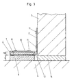
- Fig. 3 shows a typical installation situation in which the post 3 is attached as a first component to a bottom plate 4 as a second component by means of the angle connector according to the invention.
- the leg 2 of the angle connector is connected directly to the first component 3 via the corresponding fastening means.
- This rests on a cushion 14, which in turn is made for the attenuation of structure-borne noise from a corresponding sound-absorbing and / or vibration-insulating material.
- this pad 14 the direct transmission of structure-borne noise between the two components 3 and 4 is prevented.
- the intermediate layer 5 is provided according to the embodiment of the invention already explained.
- the additional intermediate layer 9 prevents the transmission of structure-borne noise via the fastening means 6 by means of which the leg 1 is fastened to the component 4.
Landscapes
- Engineering & Computer Science (AREA)
- Physics & Mathematics (AREA)
- Acoustics & Sound (AREA)
- Architecture (AREA)
- General Engineering & Computer Science (AREA)
- Structural Engineering (AREA)
- Civil Engineering (AREA)
- Electromagnetism (AREA)
- Mechanical Engineering (AREA)
- Multimedia (AREA)
- Building Environments (AREA)
- Connection Of Plates (AREA)
- Floor Finish (AREA)
- Vibration Prevention Devices (AREA)
- Soundproofing, Sound Blocking, And Sound Damping (AREA)
Abstract
Description
- Die vorliegende Erfindung betrifft einen Winkelverbinder mit zumindest zwei in einem von 0° und 180° abweichenden Winkel zueinander angeordneten Schenkeln zum Befestigen eines Bauteils an einem anderen Bauteil.
- Gattungsgemäße Winkelverbinder werden z. B. im Hochbau, insbesondere Holzbau bzw. Gebäudebau, aber auch in anderen Sparten wie z. B. dem Maschinenbau eingesetzt. Beim Stand der Technik wird einer der Schenkel des Winkelverbinders an einem der Bauteile und der andere Schenkel an dem anderen der Bauteile befestigt, was dazu führt, dass die beiden Bauteile in einem durch den Winkelverbinder vorgegebenen Winkel aneinander fixiert sind. Dabei werden die Schenkel - z. B. durch Anschrauben - direkt auf den Bauteilen befestigt, was aber die Übertragung von Körperschall insbesondere in Gebäuden fördert.
- Aufgabe der Erfindung ist es, einen gattungsgemäßen Winkelverbinder dahingehend weiter zu entwickeln, dass dieses Problem beseitigt oder zumindest vermindert wird.
- Dies wird durch einen Winkelverbinder gemäß des Patentanspruchs 1 erreicht.
- Durch die Zwischenschaltung der Zwischenschicht aus einem schalldämmenden und/oder schwingungsisolierenden Material zwischen zumindest einen der Schenkel und eines der Bauteile wird zumindest weitgehend verhindert, dass Körperschall über den Winkelverbinder von einem Bauteil auf das andere Bauteil übertragen wird. Dabei kann vorgesehen sein, dass zwischen beiden Schenkeln und den jeweils daran zu befestigen Bauteilen jeweils eine entsprechende Zwischenschicht vorgesehen ist. In der Regel reicht aber eine Zwischenschicht an einem der Schenkel aus. Unter schalldämmendem und/oder schwingungsisolierendem Material wird allgemein ein Material verstanden, das bessere Eigenschaften bezüglich der Schalldämmung bzw. Schwingungsisolierung aufweist als die Schenkel des Winkelverbinders, welche meist aus Metall, vorzugsweise Stahl, gefertigt sind.
- Als schalldämmendes und/oder schwingungsisolierendes Material für die Zwischenschicht wird günstiger Weise ein Elastomer verwendet. Die Zwischenschicht kann dabei vollständig aus diesem Material bestehen, oder auch zusätzliche Materialien aufweisen. Günstigerweise weist die Zwischenschicht einen statischen Elastizitätsmodul zwischen 0,025 N/mm2 (Newton pro Quadratmillimeter) und 5 N/mm2 bzw. einen dynamischen Elastizitätsmodul zwischen 0,025 N/mm2 und 15 N/mm2 auf. Günstigerweise wird das Material in einem Pressungsbereich zwischen 0,005 N/mm2 und 1 N/mm2 eingesetzt. Darüber hinaus ist es günstig, wenn die Zwischenschicht eine minimale Dicke von zumindest 0,4 cm, vorzugsweise von zumindest 0,6 cm, nicht unterschreitet. Bevorzugt liegt die Dicke zwischen 6 mm und 12mm, aber auch jede andere Dicke ist möglich. Besonders bevorzugte Elastomere sind, vorzugsweise aufgeschäumte, Polyurethan-Elastomere, Kautschuk-Elastomere oder auch thermoplastische Elastomere.
- Weitere Einzelheiten und Merkmale werden anhand eines erfindungsgemäßen Ausführungsbeispiels erläutert. Dabei zeigen:
-
Fig. 1 das erfindungsgemäße Ausführungsbeispiel -
Fig. 2 das Ausführungsbeispiel ausFig.1 in Explosionsdarstellung und -
Fig. 3 eine typische Einbausituation unter Verwendung des erfindungsgemäßen Ausführungsbeispiels gemäß derFig. 1 und 2 . - Der erfindungsgemäße Winkelverbinder des gezeigten Ausführungsbeispiels weist zwei im Wesentlichen orthogonal zueinander angeordnete Schenkel 1 und 2 auf. Das heißt, zwischen den Schenkeln 1 und 2 liegt ein Winkel 12 von 90° +/- 5°. Dies ist die am häufigsten verwendete Ausführungsform von Winkelverbindern. Sie kommt immer dann zum Einsatz, wenn zwei Bauteile 3 und 4 im Wesentlichen in einem 90° Winkel aneinander befestigt werden sollen. Abweichend von dem gezeigten Ausführungsbeispiel ist aber auch jeder andere, von 0° oder 180° abweichende Winkel 12 zwischen den Schenkeln 1 und 2 möglich, je nachdem in welchem Winkel die Bauteile 3 und 4 aneinander befestigt werden sollen. Bevorzugt ist vorgesehen, dass der jeweilige Winkel 12 fix ist, die beiden Schenkel 1 und 2 also nicht gegeneinander verschwenkbar sind. Abweichend davon ist es aber auch möglich, den erfindungsgemäßen Winkelverbinder mit variablem Winkel zwischen den Schenkeln 1 und 2, z. B. in Form eines Scharniers auszubilden.
- Als Befestigungsmittel 6 sind im gezeigten Ausführungsbeispiel Schrauben vorgesehen, mit welchen der Schenkel 1 am Bauteil 4 und der Schenkel 2 am Bauteil 3 befestigt werden kann. Die Schrauben 6 sind durch Befestigungslöcher 7 der Schenkel 2 hindurchgeführt. Der hier in Form eines Schraubenkopfes ausgeführte Stützkopf 11 hat jeweils einen größeren Durchmesser als das Befestigungsloch 7 und sorgt damit für eine sichere Verbindung.
- Alternativ zu den hier dargestellten Schrauben könnten natürlich auch andere beim Stand der Technik bekannte Befestigungsmittel, wie Nägel, Nieten, Bolzen, Verklebungen und dgl. verwendet werden.
- Erfindungsgemäß ist zwischen dem Schenkel 1 und dem Bauteil 4 die Zwischenschicht 5 aus schalldämmendem und/oder schwingungsisolierendem Material angeordnet. Sie reduziert die Übertragung von Körperschall von einem der Bauteile 3 oder 4 auf das andere der Bauteile 3 oder 4 über den Winkelverbinder. Die Zwischenschicht 5 erstreckt sich im gezeigten Ausführungsbeispiel über die gesamte, in Montagestellung dem Bauteil 4 zugewandte Seite des Schenkels 1. Dies muss nicht zwingend so sein. Günstig ist es jedenfalls, wenn die Zwischenschicht 5 so ausgebildet und am Schenkel 1 angeordnet ist, dass bei Befestigung des Schenkels 1 am Bauteil 4 der Schenkel 1 ausschließlich unter Zwischenschaltung der Zwischenschicht 5 und gegebenenfalls vorhandener Befestigungsmittel 6 mit dem Bauteil 4 in physischem Kontakt steht. Hierdurch wird verhindert, dass Schallbrücken vorhanden sind, über die Körperschall unter Umgehung der Zwischenschicht 5 vom Winkelverbinder auf den Bauteil übertragen werden kann. Günstig ist somit, wenn der Schenkel 1 an keiner Stelle direkt mit dem Bauteil 4 in Kontakt steht. Um dies zu erreichen, kann in Abweichung von dem gezeigten Ausführungsbeispiel auch vorgesehen sein, dass in zumindest einem der Schenkel 1, 2 Befestigungslöcher 7 zum Hindurchführen von Befestigungsmitteln 6, vorzugsweise Schrauben oder Nägeln, vorgesehen sind und die Zwischenschicht 5 zumindest in der Umgebung der Befestigungslöcher 7 angeordnet ist. Die Zwischenschicht 5 ist in diesem Fall als eine Anordnung von schalldämmenden Beilagscheiben ausgebildet. Es können aber auch andere, z. B. gitterförmige oder wabenförmige oder rahmenartige, Strukturen mit entsprechenden schalldämmenden Eigenschaften als Zwischenschicht 5 vorgesehen sein.
- Wenn die Befestigungsmittel 6 in Dübeln im Bauteil 4 gehalten sind, kann dies bereits ausreichen, um die Übertragung von Körperschall über die Befestigungsmittel 6 zu vermeiden. Sollte dies nicht der Fall sein, so kann, wie in dem hier gezeigten Ausführungsbeispiel, eine Zusatzzwischenschicht 9 vorgesehen sein, welche zumindest weitgehend verhindert, dass Körperschall über den Winkelverbinder und die Befestigungsmittel 6 zwischen den Bauteilen 3 und 4 übertragen werden kann. Die Zusatzzwischenschicht 9 weist ebenfalls schalldämmendes und/oder schwingungsisolierendes Material auf und kann aus denselben Materialien wie die Zwischenschicht 5 hergestellt sein. Auch sie muss nicht zwingend, wie im hier dargestellten Ausführungsbeispiel vollflächig ausgebildet sein. Auch die Zusatzzwischenschicht 9 muss lediglich verhindern, dass Körperschall zwischen dem Schenkel 1 und den Befestigungseinrichtungen 6 übertragen werden kann. Es sind somit auch als Zusatzzwischenschicht 9 gitter- oder waben- oder rahmen- oder beilagscheibenförmige Strukturen möglich, solange ein direkter Kontakt zwischen den Befestigungsmitteln 6 und dem Schenkel 1 zumindest in dem Umfang vermieden ist, als dass keine wirksame Schallbrücke über die Befestigungsmittel 6 entsteht.
- Die Zwischensicht 5, wie auch die Zusatzzwischenschicht 9 sind günstiger Weise am Schenkel 1 unverlierbar befestigt. Hierfür kann bereits eine Vormontage mit den Schrauben 6, wie in
Fig. 1 gezeigt, ausreichen. Es kann aber auch vorgesehen sein, dass der Schenkel 1 an der Zwischenschicht 5 und/oder der Zusatzzwischenschicht 9 angeklebt oder zwischen diesen eingegossen ist. Die Dicke 8 der Zwischenschicht 5 beträgt vorzugsweise mindestens 0,4 cm, besonders bevorzugt mindestens 0,6 cm. Günstigerweise werden Dicken zwischen 6 mm und 12 mm gewählt. Das gleiche gilt für die Dicke 13 der Zusatzzwischenschicht 9, wobei die Dicke 13 üblicherweise kleiner als die Dicke 8 ist. - Um zu verhindern, dass die Stützköpfe 11 der Befestigungsmittel 9 in das relativ weiche Material der Zusatzzwischenschicht 9 eindringen und in diesem nicht entsprechend gehalten sind, kann, wie im Ausführungsbeispiel gezeigt, eine Stützplatte 10 vorgesehen sein. Diese kann z. B. aus Metall, vorzugsweise Stahl, oder aber auch aus einem entsprechend harten und/oder zähen Kunststoff gefertigt sein. Die in ihr vorgesehenen Befestigungslöcher 7 sind wiederum in ihrem Durchmesser kleiner als die Stützköpfe 11, so dass die Befestigungsmittel 6 im entsprechend versenkten Zustand die Stützplatte 10 gegen die Zusatzzwischenschicht 9 pressen, womit der gesamte Winkelverbinder fest auf dem Bauteil 4 fixiert ist. Die Stützplatte 10 ist im gezeigten Ausführungsbeispiel wiederum einstückig ausgeführt. Auch dies muss nicht zwingend so sein. Auch hier ist als Alternative eine Anordnung aus Beilagscheiben oder eine gitterförmige Struktur oder dgl. möglich.
-
Fig. 3 zeigt eine typische Einbausituation, bei der der Pfosten 3 als erstes Bauteil an einer Bodenplatte 4 als zweitem Bauteil mittels des erfindungsgemäßen Winkelverbinders befestigt ist. Der Schenkel 2 des Winkelverbinders ist dabei direkt über die entsprechenden Befestigungsmittel mit dem ersten Bauteil 3 verbunden. Dieser ruht dabei auf einem Polster 14, welches wiederum zur Abdämmung von Körperschall aus einem entsprechend schalldämmenden und/oder schwingungsisolierenden Material gefertigt ist. Durch dieses Polster 14 wird die direkte Übertragung von Körperschall zwischen den beiden Bauteilen 3 und 4 verhindert. - Um zu vermeiden, dass Körperschall über den Winkelverbinder übertragen wird, ist gemäß des bereits erläuterten erfindungsgemäßen Ausführungsbeispiels die Zwischenschicht 5 vorgesehen. Die Zusatzzwischenschicht 9 verhindert die Übertragung von Körperschall über die Befestigungsmittel 6 mittels derer der Schenkel 1 am Bauteil 4 befestigt ist.
- Grundsätzlich ist es möglich, nicht nur einen der beiden Schenkel sondern beide Schenkel 1 und 2 mit einer entsprechenden Zwischenschicht 5 und Zusatzzwischenschicht 9 zu versehen, falls dies in besonderen Einbausituationen zur Vermeidung der Übertragung von Körperschall notwendig erscheinen sollte.
-
- 1
- Schenkel
- 2
- Schenkel
- 3
- Bauteil
- 4
- Bauteil
- 5
- Zwischenschicht
- 6
- Befestigungsmittel
- 7
- Befestigungslöcher
- 8
- Dicke
- 9
- Zusatzzwischenschicht
- 10
- Stützplatte
- 11
- Stützkopf
- 12
- Winkel
- 13
- Dicke
- 14
- Polster
Claims (18)
- Winkelverbinder mit zumindest zwei in einem von 0° und 180° abweichenden Winkel zueinander angeordneten Schenkeln (1, 2) zum Befestigen eines Bauteils (3) an einem anderen Bauteil (4), dadurch gekennzeichnet, dass an zumindest einem der Schenkel (1) zumindest eine Zwischenschicht (5) aus einem schalldämmenden und/oder schwingungsisolierenden Material angeordnet ist.
- Winkelverbinder nach Anspruch 1, dadurch gekennzeichnet, dass das schalldämmende und/oder schwingungsisolierende Material ein elastisches Material ist.
- Winkelverbinder nach Anspruch 1 oder 2, dadurch gekennzeichnet, dass die Schenkel (1, 2) im Wesentlichen orthogonal zueinander angeordnet sind.
- Winkelverbinder nach einem der Ansprüche 1 bis 3, dadurch gekennzeichnet, dass die Zwischenschicht (5) so ausgebildet und am Schenkel (1) angeordnet ist, dass bei Befestigung des Schenkels (1) am Bauteil (4) der Schenkel (1) ausschließlich unter Zwischenschaltung der Zwischenschicht (5) und gegebenenfalls vorhandener Befestigungsmittel (6) mit dem Bauteil (4) in physischem Kontakt steht.
- Winkelverbinder nach einem der Ansprüche 1 bis 4, dadurch gekennzeichnet, dass in zumindest einem der Schenkel (1, 2) Befestigungslöcher (7) zum Hindurchführen von Befestigungsmitteln (6), vorzugsweise Schrauben oder Nägeln, vorgesehen sind.
- Winkelverbinder nach Anspruch 5, dadurch gekennzeichnet, dass die Zwischenschicht (5) zumindest in der Umgebung der Befestigungslöcher (7) angeordnet ist.
- Winkelverbinder nach einem der Ansprüche 1 bis 6, dadurch gekennzeichnet, dass die Zwischenschicht (5) auf der gesamten, in Montagestellung dem Bauteil (4) zugewandten Seite des Schenkels (1) angeordnet ist.
- Winkelverbinder nach einem der Ansprüche 1 bis 7, dadurch gekennzeichnet, dass die Zwischenschicht (5) am Schenkel (1) unverlierbar befestigt, vorzugsweise angeklebt, ist.
- Winkelverbinder nach einem der Ansprüche 1 bis 8, dadurch gekennzeichnet, dass die Schenkel (1, 2) aus Metall, vorzugsweise aus Stahl, gefertigt sind.
- Winkelverbinder nach einem der Ansprüche 1 bis 9, dadurch gekennzeichnet, dass die Zwischenschicht (5) eine minimale Dicke (8) von zumindest 0,4 cm, vorzugsweise von zumindest 0,6 cm, aufweist.
- Winkelverbinder nach einem der Ansprüche 1 bis 10, dadurch gekennzeichnet, dass auf der der Zwischenschicht (5) entgegengesetzten Seite des Schenkels (1) eine Zusatzzwischenschicht (9) aus einem schalldämmenden und/oder schwingungsisolierenden Material in der Weise angeordnet ist, dass Befestigungsmittel (6) zur Befestigung des Schenkels (1) am Bauteil (4) im Wesentlichen ausschließlich über die Zusatzzwischenschicht (9) und die Zwischenschicht (5) mit dem Schenkel (1) in Verbindung stehen.
- Winkelverbinder nach Anspruch 11, dadurch gekennzeichnet, dass auf der dem Schenkel (1) entgegengesetzten Seite der Zusatzzwischenschicht (9) eine oder mehrere Stützplatten (10) angeordnet sind, mit welchen Stützköpfe (11) der Befestigungsmittel (6) abstützbar sind.
- Winkelverbinder nach Anspruch 11 oder 12, dadurch gekennzeichnet, dass in zumindest einem der Schenkel (1, 2) Befestigungslöcher (7) zum Hindurchführen von Befestigungsmitteln (6), vorzugsweise Schrauben oder Nägeln, vorgesehen sind und die Zusatzzwischenschicht (9) zumindest in der Umgebung der Befestigungslöcher (7) angeordnet ist.
- Winkelverbinder nach einem der Ansprüche 11 bis 13, dadurch gekennzeichnet, dass die Zusatzzwischenschicht (9) auf der der gesamten, in Montagestellung dem Bauteil (4) zugewandten Seite des Schenkels (1) gegenüberliegenden Seite des Schenkels (1) angeordnet ist.
- Winkelverbinder nach einem der Ansprüche 11 bis 14, dadurch gekennzeichnet, dass das schalldämmende und/oder schwingungsisolierende Material ein elastisches Material ist.
- Winkelverbinder nach einem der Ansprüche 1 bis 15, dadurch gekennzeichnet, dass die Zwischenschicht (5) und/oder die gegebenenfalls vorhandene Zusatzzwischenschicht (9) einen statischen Elastizitätsmodul zwischen 0,025 N/mm2 und 5N/mm2 aufweist (aufweisen).
- Winkelverbinder nach einem der Ansprüche 1 bis 16, dadurch gekennzeichnet, dass die Zwischenschicht (5) und/oder die gegebenenfalls vorhandene Zusatzzwischenschicht (9) ein Elastomer aufweist (aufweisen).
- Winkelverbinder nach einem der Ansprüche 1 bis 16, dadurch gekennzeichnet, dass die Zwischenschicht (5) und/oder die gegebenenfalls vorhandene Zusatzzwischenschicht (9) ein, vorzugsweise aufgeschäumtes, Polyurethan- Elastomer oder ein Kautschuk- Elastomer oder ein thermoplastisches Elastomer aufweist (aufweisen).
Applications Claiming Priority (1)
| Application Number | Priority Date | Filing Date | Title |
|---|---|---|---|
| AT0124207A AT504913B1 (de) | 2007-08-08 | 2007-08-08 | Winkelverbinder |
Publications (3)
| Publication Number | Publication Date |
|---|---|
| EP2022902A2 true EP2022902A2 (de) | 2009-02-11 |
| EP2022902A3 EP2022902A3 (de) | 2012-06-20 |
| EP2022902B1 EP2022902B1 (de) | 2014-11-05 |
Family
ID=39735867
Family Applications (1)
| Application Number | Title | Priority Date | Filing Date |
|---|---|---|---|
| EP08005552.8A Active EP2022902B1 (de) | 2007-08-08 | 2008-03-25 | Winkelverbinder |
Country Status (5)
| Country | Link |
|---|---|
| US (1) | US20090038882A1 (de) |
| EP (1) | EP2022902B1 (de) |
| JP (1) | JP2009041774A (de) |
| AT (1) | AT504913B1 (de) |
| CA (1) | CA2638507C (de) |
Cited By (6)
| Publication number | Priority date | Publication date | Assignee | Title |
|---|---|---|---|---|
| EP3486388A1 (de) * | 2017-11-15 | 2019-05-22 | Pitzl Metallbau GmbH & Co. KG | Verbindungsvorrichtung zum verbinden zweier bauteile und bauteilanordnung mit einer solchen verbindungseinrichtung |
| AT522697B1 (de) * | 2019-09-16 | 2021-01-15 | Franz Dipl Ing Lesjak | Leibungswinkel verstell bar |
| AT524008A1 (de) * | 2020-07-14 | 2022-01-15 | Vh Holding Gmbh | Winkelverbinder |
| AT18152U1 (de) * | 2023-02-13 | 2024-03-15 | Pitzl Metallbau Gmbh & Co Kg | Flachverbindungsvorrichtung zum Verbinden zweier Bauteile und Bauteilanordnung mit einer solchen Flachverbindungsvorrichtung |
| EP4345336A1 (de) * | 2022-09-23 | 2024-04-03 | Getzner Werkstoffe Holding GmbH | Lagerfuss |
| WO2024079254A1 (de) * | 2022-10-13 | 2024-04-18 | Vh Holding Gmbh | Winkelverbinder |
Families Citing this family (10)
| Publication number | Priority date | Publication date | Assignee | Title |
|---|---|---|---|---|
| AT508174B1 (de) * | 2009-04-28 | 2011-07-15 | Getzner Werkstoffe Holding Gmbh | Verbindungseinrichtung |
| WO2011081009A1 (en) * | 2009-12-28 | 2011-07-07 | Semiconductor Energy Laboratory Co., Ltd. | Method for manufacturing semiconductor device |
| DE102017009690A1 (de) | 2016-10-17 | 2018-04-19 | JORDAHL GmbH | Stahlbetonbauwerk |
| DE202017005581U1 (de) | 2017-02-09 | 2018-01-10 | JORDAHL GmbH | Akustische Isolierung |
| DE202017005241U1 (de) | 2017-10-10 | 2017-11-30 | JORDAHL GmbH | Akustische lsolierung |
| DE102019000124A1 (de) | 2019-01-11 | 2020-07-16 | JORDAHL GmbH | Stahlbetonbauwerk |
| WO2020162866A1 (en) * | 2019-02-04 | 2020-08-13 | Hewlett-Packard Development Company, L.P. | Output device orientations adjustments |
| EP3739233A1 (de) * | 2019-05-15 | 2020-11-18 | Aqseptence Group GmbH | Installationsanordnung für eine toilettenschüssel |
| BE1030721B1 (nl) | 2022-07-18 | 2024-02-12 | Cdm Stravitec | Verbindingssysteem voor gebouwmodules |
| US12516690B2 (en) * | 2024-02-08 | 2026-01-06 | My-Ti-Con Timber Connectors Inc. | Beam connector, connector member thereof, drill jig therefor, and beam assembly comprising the same |
Citations (3)
| Publication number | Priority date | Publication date | Assignee | Title |
|---|---|---|---|---|
| DE8707806U1 (de) | 1987-06-02 | 1987-09-24 | Dick, René, 5000 Köln | Kanalhalter |
| DE3904036A1 (de) | 1989-02-10 | 1990-08-16 | Leo Koestler | Vorrichtung zum druck- und zugfesten und bezueglich koerperschall entkoppelten verbinden zweier teile |
| US20060042874A1 (en) | 2004-08-24 | 2006-03-02 | Matthew Foster | Acoustical and firewall barrier assembly |
Family Cites Families (23)
| Publication number | Priority date | Publication date | Assignee | Title |
|---|---|---|---|---|
| US3130700A (en) * | 1960-04-29 | 1964-04-28 | Robert E Peterson | Vibration and mechanical wave damping |
| US3574080A (en) * | 1966-11-18 | 1971-04-06 | Mc Donnell Douglas Corp | Corrosion inhibiting fastener means |
| CA994375A (en) * | 1968-07-19 | 1976-08-03 | Minnesota Mining And Manufacturing Company | Damping unit |
| DE8107689U1 (de) * | 1981-03-17 | 1981-09-24 | Dipa - Matthias und René Dick GmbH, 5000 Köln | Schalldaemmendes element |
| JPS6116916A (ja) * | 1984-07-04 | 1986-01-24 | Dainippon Ink & Chem Inc | 防振材 |
| JPS6326016U (de) * | 1986-08-04 | 1988-02-20 | ||
| JP3221097B2 (ja) * | 1992-10-23 | 2001-10-22 | 住友化学工業株式会社 | 防振ゴム組成物及び加硫防振ゴム組成物 |
| US5947431A (en) * | 1995-08-10 | 1999-09-07 | Pass & Seymour, Inc. | Merchandise display support |
| US5690305A (en) * | 1996-01-23 | 1997-11-25 | Perkins; Kristine M. | Bracket for positioning skirting on a manufactured building |
| US5846018A (en) * | 1996-08-26 | 1998-12-08 | Super Stud Building Products, Inc. | Deflection slide clip |
| DE29718172U1 (de) * | 1997-10-14 | 1997-11-27 | GH-Baubeschläge Hartmann GmbH, 32549 Bad Oeynhausen | Winkelverbinder |
| GB2341403B (en) * | 1998-09-11 | 2003-02-05 | Hillaldam Coburn Ltd | A support |
| US6494639B1 (en) * | 1999-05-01 | 2002-12-17 | Universal Services, Inc. | Primary connector for pre-cast structures |
| US6266939B1 (en) * | 1999-10-26 | 2001-07-31 | Randall E. Yates | Method for containing debris |
| JP3280655B2 (ja) * | 2000-04-11 | 2002-05-13 | 株式会社山口安製作所 | 汎用隅金 |
| US6986489B2 (en) * | 2001-06-19 | 2006-01-17 | Innovative Office Products, Inc. | Configurable mount for a peripheral device |
| JP3897548B2 (ja) * | 2001-07-31 | 2007-03-28 | 日野自動車株式会社 | ラバークッション |
| US7065932B2 (en) * | 2003-10-06 | 2006-06-27 | Simpson Strong-Tie Company, Inc. | Top flange stud to plate tie |
| US7503150B1 (en) * | 2003-10-20 | 2009-03-17 | The Steel Network, Inc. | Connector assembly for allowing relative movement between two building members |
| US7104024B1 (en) * | 2003-10-20 | 2006-09-12 | The Steel Network, Inc. | Connector for connecting two building members together that permits relative movement between the building members |
| US7478508B2 (en) * | 2004-08-16 | 2009-01-20 | Scafco Corporation | Mounting clip |
| US7837147B2 (en) * | 2005-03-18 | 2010-11-23 | The Boeing Company | Systems and methods for reducing noise in aircraft fuselages and other structures |
| US7568680B2 (en) * | 2006-04-18 | 2009-08-04 | Platt Robert E | Rail clip assembly for connecting a fence rail to a fence post |
-
2007
- 2007-08-08 AT AT0124207A patent/AT504913B1/de active
-
2008
- 2008-03-25 EP EP08005552.8A patent/EP2022902B1/de active Active
- 2008-08-04 CA CA 2638507 patent/CA2638507C/en active Active
- 2008-08-06 US US12/186,664 patent/US20090038882A1/en not_active Abandoned
- 2008-08-07 JP JP2008203769A patent/JP2009041774A/ja active Pending
Patent Citations (3)
| Publication number | Priority date | Publication date | Assignee | Title |
|---|---|---|---|---|
| DE8707806U1 (de) | 1987-06-02 | 1987-09-24 | Dick, René, 5000 Köln | Kanalhalter |
| DE3904036A1 (de) | 1989-02-10 | 1990-08-16 | Leo Koestler | Vorrichtung zum druck- und zugfesten und bezueglich koerperschall entkoppelten verbinden zweier teile |
| US20060042874A1 (en) | 2004-08-24 | 2006-03-02 | Matthew Foster | Acoustical and firewall barrier assembly |
Cited By (8)
| Publication number | Priority date | Publication date | Assignee | Title |
|---|---|---|---|---|
| EP3486388A1 (de) * | 2017-11-15 | 2019-05-22 | Pitzl Metallbau GmbH & Co. KG | Verbindungsvorrichtung zum verbinden zweier bauteile und bauteilanordnung mit einer solchen verbindungseinrichtung |
| AT522697B1 (de) * | 2019-09-16 | 2021-01-15 | Franz Dipl Ing Lesjak | Leibungswinkel verstell bar |
| AT522697A4 (de) * | 2019-09-16 | 2021-01-15 | Franz Dipl Ing Lesjak | Leibungswinkel verstell bar |
| EP3792506A1 (de) | 2019-09-16 | 2021-03-17 | Franz Albert Lesjak | Variabel verstellbarer und fixierbarer winkelverbinder |
| AT524008A1 (de) * | 2020-07-14 | 2022-01-15 | Vh Holding Gmbh | Winkelverbinder |
| EP4345336A1 (de) * | 2022-09-23 | 2024-04-03 | Getzner Werkstoffe Holding GmbH | Lagerfuss |
| WO2024079254A1 (de) * | 2022-10-13 | 2024-04-18 | Vh Holding Gmbh | Winkelverbinder |
| AT18152U1 (de) * | 2023-02-13 | 2024-03-15 | Pitzl Metallbau Gmbh & Co Kg | Flachverbindungsvorrichtung zum Verbinden zweier Bauteile und Bauteilanordnung mit einer solchen Flachverbindungsvorrichtung |
Also Published As
| Publication number | Publication date |
|---|---|
| CA2638507C (en) | 2015-03-31 |
| EP2022902B1 (de) | 2014-11-05 |
| US20090038882A1 (en) | 2009-02-12 |
| EP2022902A3 (de) | 2012-06-20 |
| JP2009041774A (ja) | 2009-02-26 |
| AT504913B1 (de) | 2008-09-15 |
| AT504913A4 (de) | 2008-09-15 |
| CA2638507A1 (en) | 2009-02-08 |
Similar Documents
| Publication | Publication Date | Title |
|---|---|---|
| EP2022902B1 (de) | Winkelverbinder | |
| DE10021575A1 (de) | Vorrichtung zur insbesondere akustisch entkoppelten Befestigung | |
| DE212020000638U1 (de) | Kombinierte Vorrichtung zur Lärmminderung und Schalldämpfung für eine Schiene | |
| EP2035635A1 (de) | Verbindungselement für c-profile mit ausgleichsmittel und anordnung | |
| EP3144448B1 (de) | Montageplatte zur befestigung eines bauteils an einer wand | |
| EP3772443B1 (de) | Schienenfahrzeug mit mindestens einem fussbodenaufbau | |
| EP3760432B1 (de) | Verkleidungsteil und schalldämmhaube für eine wärmepumpe | |
| DE102019114492A1 (de) | Befestigungssystem mit Kraftverteilung | |
| DE102015202979B4 (de) | Schwingungsdämpfungseinrichtung | |
| DE3306245C2 (de) | Elastisches Auflager für Baukonstruktionen | |
| AT524008A1 (de) | Winkelverbinder | |
| DE102009049178A1 (de) | Schalung | |
| DE102007044494A1 (de) | Vorrichtung umfassend ein Funktionselement einer Brennkraftmaschine und einen Träger | |
| EP4345210B1 (de) | Schienenlagerungseinrichtung zur schalldämpfenden lagerung einer schiene | |
| EP4428084B1 (de) | Schallisolierungseinrichtung für aufzüge sowie aufzugsanordnung | |
| DE202008014040U1 (de) | Schallisolierender Befestigungsflansch | |
| WO2007112773A1 (de) | Befestigungseinrichtung für bauelemente des trockenbaus | |
| DE102006058783A1 (de) | Schalldämmelement | |
| EP2775087B1 (de) | Schalltechnisches Trennelement mit Dichtfunktion | |
| DE102015210472B4 (de) | Befestigungsanordnung eines Instrumententafelträgers an einer Stirnwand eines Kraftfahrzeuges | |
| DE202017005241U1 (de) | Akustische lsolierung | |
| DE202017005581U1 (de) | Akustische Isolierung | |
| EP2103739B1 (de) | Einrichtung zum Bilden einer Schalldämmung an einer Dehnungsfuge | |
| DE10359515A1 (de) | Elastisches Verbindungselement | |
| DE202009016150U1 (de) | Lichtschacht mit verbesserter Dichtvorrichtung |
Legal Events
| Date | Code | Title | Description |
|---|---|---|---|
| PUAI | Public reference made under article 153(3) epc to a published international application that has entered the european phase |
Free format text: ORIGINAL CODE: 0009012 |
|
| AK | Designated contracting states |
Kind code of ref document: A2 Designated state(s): AT BE BG CH CY CZ DE DK EE ES FI FR GB GR HR HU IE IS IT LI LT LU LV MC MT NL NO PL PT RO SE SI SK TR |
|
| AX | Request for extension of the european patent |
Extension state: AL BA MK RS |
|
| PUAL | Search report despatched |
Free format text: ORIGINAL CODE: 0009013 |
|
| AK | Designated contracting states |
Kind code of ref document: A3 Designated state(s): AT BE BG CH CY CZ DE DK EE ES FI FR GB GR HR HU IE IS IT LI LT LU LV MC MT NL NO PL PT RO SE SI SK TR |
|
| AX | Request for extension of the european patent |
Extension state: AL BA MK RS |
|
| RIC1 | Information provided on ipc code assigned before grant |
Ipc: E04B 1/82 20060101AFI20120515BHEP Ipc: F16F 1/373 20060101ALI20120515BHEP |
|
| 17P | Request for examination filed |
Effective date: 20121214 |
|
| AKX | Designation fees paid |
Designated state(s): AT BE BG CH CY CZ DE DK EE ES FI FR GB GR HR HU IE IS IT LI LT LU LV MC MT NL NO PL PT RO SE SI SK TR |
|
| 17Q | First examination report despatched |
Effective date: 20130808 |
|
| GRAP | Despatch of communication of intention to grant a patent |
Free format text: ORIGINAL CODE: EPIDOSNIGR1 |
|
| INTG | Intention to grant announced |
Effective date: 20140516 |
|
| GRAP | Despatch of communication of intention to grant a patent |
Free format text: ORIGINAL CODE: EPIDOSNIGR1 |
|
| INTG | Intention to grant announced |
Effective date: 20140624 |
|
| GRAP | Despatch of communication of intention to grant a patent |
Free format text: ORIGINAL CODE: EPIDOSNIGR1 |
|
| INTG | Intention to grant announced |
Effective date: 20140729 |
|
| GRAS | Grant fee paid |
Free format text: ORIGINAL CODE: EPIDOSNIGR3 |
|
| GRAA | (expected) grant |
Free format text: ORIGINAL CODE: 0009210 |
|
| AK | Designated contracting states |
Kind code of ref document: B1 Designated state(s): AT BE BG CH CY CZ DE DK EE ES FI FR GB GR HR HU IE IS IT LI LT LU LV MC MT NL NO PL PT RO SE SI SK TR |
|
| REG | Reference to a national code |
Ref country code: GB Ref legal event code: FG4D Free format text: NOT ENGLISH |
|
| REG | Reference to a national code |
Ref country code: CH Ref legal event code: EP |
|
| REG | Reference to a national code |
Ref country code: AT Ref legal event code: REF Ref document number: 694752 Country of ref document: AT Kind code of ref document: T Effective date: 20141115 |
|
| REG | Reference to a national code |
Ref country code: CH Ref legal event code: NV Representative=s name: ALDO ROEMPLER PATENTANWALT, CH |
|
| REG | Reference to a national code |
Ref country code: IE Ref legal event code: FG4D Free format text: LANGUAGE OF EP DOCUMENT: GERMAN |
|
| REG | Reference to a national code |
Ref country code: DE Ref legal event code: R096 Ref document number: 502008012364 Country of ref document: DE Effective date: 20141218 |
|
| REG | Reference to a national code |
Ref country code: SE Ref legal event code: TRGR |
|
| REG | Reference to a national code |
Ref country code: NL Ref legal event code: VDEP Effective date: 20141105 |
|
| REG | Reference to a national code |
Ref country code: LT Ref legal event code: MG4D |
|
| PG25 | Lapsed in a contracting state [announced via postgrant information from national office to epo] |
Ref country code: FI Free format text: LAPSE BECAUSE OF FAILURE TO SUBMIT A TRANSLATION OF THE DESCRIPTION OR TO PAY THE FEE WITHIN THE PRESCRIBED TIME-LIMIT Effective date: 20141105 Ref country code: IS Free format text: LAPSE BECAUSE OF FAILURE TO SUBMIT A TRANSLATION OF THE DESCRIPTION OR TO PAY THE FEE WITHIN THE PRESCRIBED TIME-LIMIT Effective date: 20150305 Ref country code: PT Free format text: LAPSE BECAUSE OF FAILURE TO SUBMIT A TRANSLATION OF THE DESCRIPTION OR TO PAY THE FEE WITHIN THE PRESCRIBED TIME-LIMIT Effective date: 20150305 Ref country code: NL Free format text: LAPSE BECAUSE OF FAILURE TO SUBMIT A TRANSLATION OF THE DESCRIPTION OR TO PAY THE FEE WITHIN THE PRESCRIBED TIME-LIMIT Effective date: 20141105 Ref country code: LT Free format text: LAPSE BECAUSE OF FAILURE TO SUBMIT A TRANSLATION OF THE DESCRIPTION OR TO PAY THE FEE WITHIN THE PRESCRIBED TIME-LIMIT Effective date: 20141105 Ref country code: NO Free format text: LAPSE BECAUSE OF FAILURE TO SUBMIT A TRANSLATION OF THE DESCRIPTION OR TO PAY THE FEE WITHIN THE PRESCRIBED TIME-LIMIT Effective date: 20150205 Ref country code: ES Free format text: LAPSE BECAUSE OF FAILURE TO SUBMIT A TRANSLATION OF THE DESCRIPTION OR TO PAY THE FEE WITHIN THE PRESCRIBED TIME-LIMIT Effective date: 20141105 |
|
| PG25 | Lapsed in a contracting state [announced via postgrant information from national office to epo] |
Ref country code: CY Free format text: LAPSE BECAUSE OF FAILURE TO SUBMIT A TRANSLATION OF THE DESCRIPTION OR TO PAY THE FEE WITHIN THE PRESCRIBED TIME-LIMIT Effective date: 20141105 Ref country code: LV Free format text: LAPSE BECAUSE OF FAILURE TO SUBMIT A TRANSLATION OF THE DESCRIPTION OR TO PAY THE FEE WITHIN THE PRESCRIBED TIME-LIMIT Effective date: 20141105 Ref country code: HR Free format text: LAPSE BECAUSE OF FAILURE TO SUBMIT A TRANSLATION OF THE DESCRIPTION OR TO PAY THE FEE WITHIN THE PRESCRIBED TIME-LIMIT Effective date: 20141105 Ref country code: GR Free format text: LAPSE BECAUSE OF FAILURE TO SUBMIT A TRANSLATION OF THE DESCRIPTION OR TO PAY THE FEE WITHIN THE PRESCRIBED TIME-LIMIT Effective date: 20150206 Ref country code: PL Free format text: LAPSE BECAUSE OF FAILURE TO SUBMIT A TRANSLATION OF THE DESCRIPTION OR TO PAY THE FEE WITHIN THE PRESCRIBED TIME-LIMIT Effective date: 20141105 |
|
| PG25 | Lapsed in a contracting state [announced via postgrant information from national office to epo] |
Ref country code: SK Free format text: LAPSE BECAUSE OF FAILURE TO SUBMIT A TRANSLATION OF THE DESCRIPTION OR TO PAY THE FEE WITHIN THE PRESCRIBED TIME-LIMIT Effective date: 20141105 Ref country code: RO Free format text: LAPSE BECAUSE OF FAILURE TO SUBMIT A TRANSLATION OF THE DESCRIPTION OR TO PAY THE FEE WITHIN THE PRESCRIBED TIME-LIMIT Effective date: 20141105 Ref country code: CZ Free format text: LAPSE BECAUSE OF FAILURE TO SUBMIT A TRANSLATION OF THE DESCRIPTION OR TO PAY THE FEE WITHIN THE PRESCRIBED TIME-LIMIT Effective date: 20141105 Ref country code: EE Free format text: LAPSE BECAUSE OF FAILURE TO SUBMIT A TRANSLATION OF THE DESCRIPTION OR TO PAY THE FEE WITHIN THE PRESCRIBED TIME-LIMIT Effective date: 20141105 Ref country code: DK Free format text: LAPSE BECAUSE OF FAILURE TO SUBMIT A TRANSLATION OF THE DESCRIPTION OR TO PAY THE FEE WITHIN THE PRESCRIBED TIME-LIMIT Effective date: 20141105 |
|
| REG | Reference to a national code |
Ref country code: DE Ref legal event code: R097 Ref document number: 502008012364 Country of ref document: DE |
|
| PLBE | No opposition filed within time limit |
Free format text: ORIGINAL CODE: 0009261 |
|
| STAA | Information on the status of an ep patent application or granted ep patent |
Free format text: STATUS: NO OPPOSITION FILED WITHIN TIME LIMIT |
|
| 26N | No opposition filed |
Effective date: 20150806 |
|
| PG25 | Lapsed in a contracting state [announced via postgrant information from national office to epo] |
Ref country code: LU Free format text: LAPSE BECAUSE OF FAILURE TO SUBMIT A TRANSLATION OF THE DESCRIPTION OR TO PAY THE FEE WITHIN THE PRESCRIBED TIME-LIMIT Effective date: 20150325 Ref country code: MC Free format text: LAPSE BECAUSE OF FAILURE TO SUBMIT A TRANSLATION OF THE DESCRIPTION OR TO PAY THE FEE WITHIN THE PRESCRIBED TIME-LIMIT Effective date: 20141105 |
|
| GBPC | Gb: european patent ceased through non-payment of renewal fee |
Effective date: 20150325 |
|
| REG | Reference to a national code |
Ref country code: IE Ref legal event code: MM4A |
|
| PG25 | Lapsed in a contracting state [announced via postgrant information from national office to epo] |
Ref country code: IE Free format text: LAPSE BECAUSE OF NON-PAYMENT OF DUE FEES Effective date: 20150325 Ref country code: GB Free format text: LAPSE BECAUSE OF NON-PAYMENT OF DUE FEES Effective date: 20150325 |
|
| PG25 | Lapsed in a contracting state [announced via postgrant information from national office to epo] |
Ref country code: SI Free format text: LAPSE BECAUSE OF FAILURE TO SUBMIT A TRANSLATION OF THE DESCRIPTION OR TO PAY THE FEE WITHIN THE PRESCRIBED TIME-LIMIT Effective date: 20141105 |
|
| REG | Reference to a national code |
Ref country code: FR Ref legal event code: PLFP Year of fee payment: 9 |
|
| REG | Reference to a national code |
Ref country code: AT Ref legal event code: MM01 Ref document number: 694752 Country of ref document: AT Kind code of ref document: T Effective date: 20150325 |
|
| PG25 | Lapsed in a contracting state [announced via postgrant information from national office to epo] |
Ref country code: AT Free format text: LAPSE BECAUSE OF NON-PAYMENT OF DUE FEES Effective date: 20150325 |
|
| PG25 | Lapsed in a contracting state [announced via postgrant information from national office to epo] |
Ref country code: MT Free format text: LAPSE BECAUSE OF FAILURE TO SUBMIT A TRANSLATION OF THE DESCRIPTION OR TO PAY THE FEE WITHIN THE PRESCRIBED TIME-LIMIT Effective date: 20141105 |
|
| PG25 | Lapsed in a contracting state [announced via postgrant information from national office to epo] |
Ref country code: IT Free format text: LAPSE BECAUSE OF NON-PAYMENT OF DUE FEES Effective date: 20160325 |
|
| REG | Reference to a national code |
Ref country code: FR Ref legal event code: PLFP Year of fee payment: 10 |
|
| PG25 | Lapsed in a contracting state [announced via postgrant information from national office to epo] |
Ref country code: BG Free format text: LAPSE BECAUSE OF FAILURE TO SUBMIT A TRANSLATION OF THE DESCRIPTION OR TO PAY THE FEE WITHIN THE PRESCRIBED TIME-LIMIT Effective date: 20141105 Ref country code: HU Free format text: LAPSE BECAUSE OF FAILURE TO SUBMIT A TRANSLATION OF THE DESCRIPTION OR TO PAY THE FEE WITHIN THE PRESCRIBED TIME-LIMIT; INVALID AB INITIO Effective date: 20080325 |
|
| PG25 | Lapsed in a contracting state [announced via postgrant information from national office to epo] |
Ref country code: BE Free format text: LAPSE BECAUSE OF NON-PAYMENT OF DUE FEES Effective date: 20150331 |
|
| PG25 | Lapsed in a contracting state [announced via postgrant information from national office to epo] |
Ref country code: IT Free format text: LAPSE BECAUSE OF NON-PAYMENT OF DUE FEES Effective date: 20160325 Ref country code: TR Free format text: LAPSE BECAUSE OF FAILURE TO SUBMIT A TRANSLATION OF THE DESCRIPTION OR TO PAY THE FEE WITHIN THE PRESCRIBED TIME-LIMIT Effective date: 20141105 |
|
| PGRI | Patent reinstated in contracting state [announced from national office to epo] |
Ref country code: IT Effective date: 20170710 |
|
| REG | Reference to a national code |
Ref country code: FR Ref legal event code: PLFP Year of fee payment: 11 |
|
| PGFP | Annual fee paid to national office [announced via postgrant information from national office to epo] |
Ref country code: FR Payment date: 20210326 Year of fee payment: 14 Ref country code: CH Payment date: 20210322 Year of fee payment: 14 |
|
| REG | Reference to a national code |
Ref country code: CH Ref legal event code: PL |
|
| PG25 | Lapsed in a contracting state [announced via postgrant information from national office to epo] |
Ref country code: LI Free format text: LAPSE BECAUSE OF NON-PAYMENT OF DUE FEES Effective date: 20220331 Ref country code: FR Free format text: LAPSE BECAUSE OF NON-PAYMENT OF DUE FEES Effective date: 20220331 Ref country code: CH Free format text: LAPSE BECAUSE OF NON-PAYMENT OF DUE FEES Effective date: 20220331 |
|
| PGFP | Annual fee paid to national office [announced via postgrant information from national office to epo] |
Ref country code: SE Payment date: 20260323 Year of fee payment: 19 |
|
| PGFP | Annual fee paid to national office [announced via postgrant information from national office to epo] |
Ref country code: DE Payment date: 20260320 Year of fee payment: 19 |
|
| PGFP | Annual fee paid to national office [announced via postgrant information from national office to epo] |
Ref country code: IT Payment date: 20260320 Year of fee payment: 19 |